

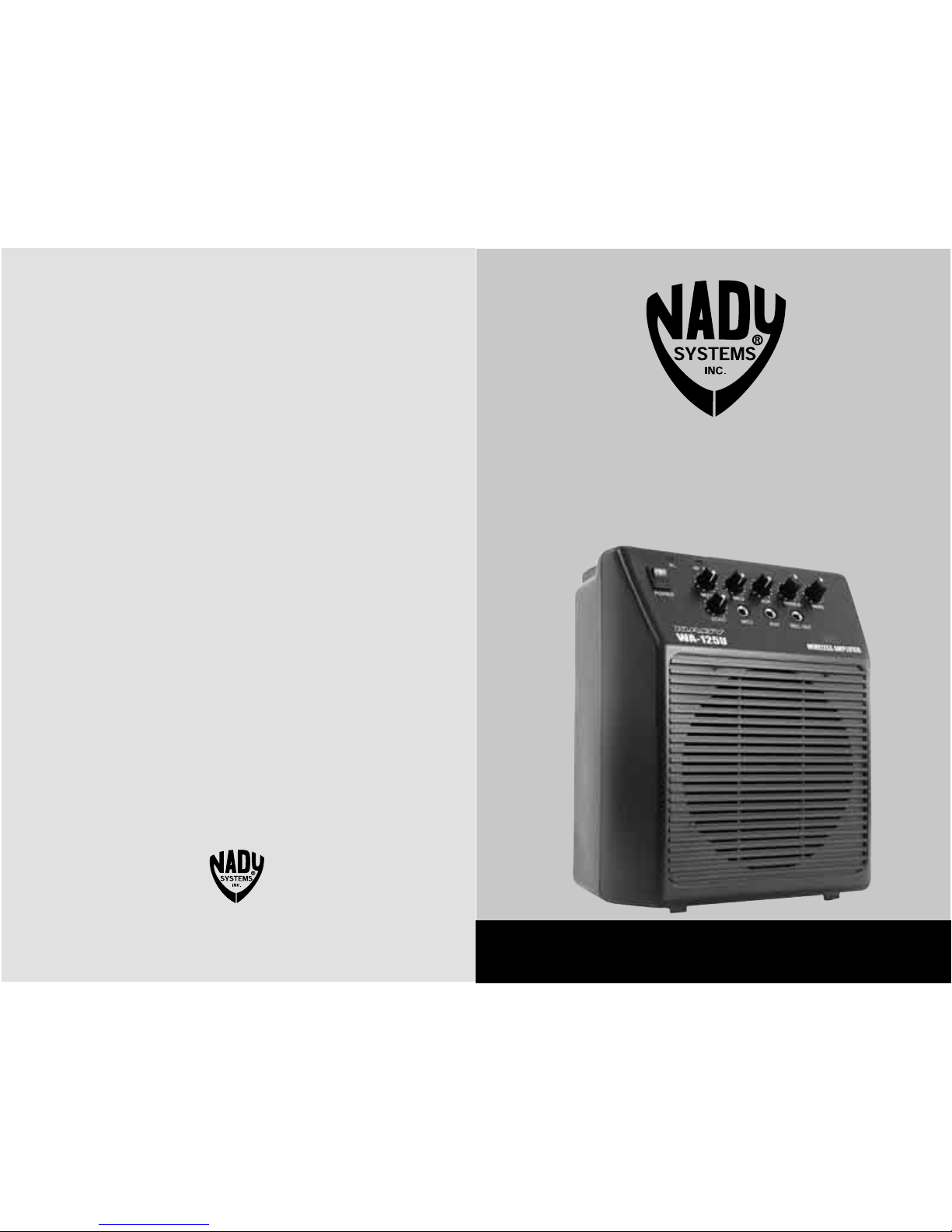
Nady Systems WA-125U Owner's Manual
NADY SYSTEMS, INC.
6701 Shellmound Street • Emeryville, CA 94608
Tel: 510.652.2411 • Fax: 510.652.5075 • www.nady.com
SERVICE INFORMATION
(U.S.) If you are experiencing operation problem with your system, check out the support
page on the Nady website: www.nady.com for help and for contacting the Nady Service
Department. Should your wireless System require service, you must contact the Nady Service
Department at (510) 652-2411 for a Return Authorization (R/A) Number and a service quote
(if out of warranty). Make sure the R/A Number is clearly marked on the outside of the package. Cashier’s check or money is enclosed (If not prepaid with credit card), and ship the unit
prepaid to: Nady System Inc., Service Department, 6701 Shellmound Street, Emeryville, CA
94608. Include a brief description of the problem you are experiencing, for service of a unit
under warranty follow the instruction of your Warranty Card regarding Warranty Service.
(International) For service, please contact the NADY distributors in your country through the
dealer from whom you purchase this product.
DO NOT ATTEMPT TO SERVICE THIS UNIT YOURSELF, AS THAT WILL VOID YOUR
WARRANTY.
OWNE R’S MA NUAL
WA-125U
Single Channel UHF Wireless
Portable PA System

15
SPECIFICATIONS
AMPLIFIER SPECIFICATIONS
Audio Output Power ......................................................................................................... 20W (MAX)
Speaker Load ........................................................................................4 Ohms (6-1/2 inch Speaker)
Supply Voltage ..................................................................External AC adaptor or DC (12-15V)/1.2A
Internal Power 8xD alkaline or 12V/1.2A rechargeable battery
Power Consumption .................................................................................................................40VAC
Connectors ..............................................AC/DC in, 1/4” (6.3 mm) unbalanced MIC/AUX/REC jacks
Input Sensitivity MIC, AUX .......................................................................................... 18mV, 132mV
REC output level ......................................................................................................................360mV
Frequency Response .......................................................................................50Hz to 20kHz +/-3dB
Total Harmonic Distortion ....................................................................................... <1% THD, normal
Signal-to-Noise Ratio (at rated output) ...................................................................................... -75dB
Tone Control Range ...............................................................+/-5dB (BASS 100Hz/TREBLE 10kHz)
Volume/Level Controls ...............................................................MICS, AUX, ECHO, BASS/TREBLE
9V battery Charger Current .............................................................................................. 5-70mA DC
Dimension ............................................................................ 8.3” x 10.6” x 5.4” (211 x 270 x 137mm)
Weight ...........................................................................................................................5.3lbs (2.4kg)
WIRELESS RECEIVER SPECIFICATIONS
Frequency Response ...........................................................................................100Hz-16kHz, -3dB
Harmonic Distortion ............................................................................................. <0.6% THD, normal
Signal-to-Noise Ratio (REC out) ............................................................................................... -80dB
RF Carrier Frequency........................................... ........ Single UHF Frequency (797-805MHz range)
Frequency stability ..............................................................................+/- 0.005% Crystal Controlled
Modulation ............................................................................................... FM (F3E), +/-20kHz normal
Unwanted Signal Rejection .......................................................................60dB image and spurious
Squelch Controls ..................................................... External adjustable (-65dBm/Min, -95dBm/Max)
LED Indicators ..................................................................................................RF ON (GREEN LED)
Antennas ............................................................................................4.0” (10.2 cm) Internal antenna
Operating Range ................................................. Up to 200 ft. typical (depending on site conditions)
Up to 300+ feet (optimum line-of-sight)
TRANSMITTER SPECIFICATIONS
Models Available .....................UH-4 Handheld, UB-4 Bodypack, and LINK 4 SNAP-ON transmitters
RF Output Power ................. +14dBm (25mW normal), +17dBm (50mW maximum allowed by FCC)
Harmonic/spurious .......................................................................................................-50dBc normal
Antenna Type .....................................................UH-4: Integral. UB-4: External permanent attached
LINK 4: Integral into hardwire Mic
Controls ................................................. Transmitter ON/Mute/OFF switch, Audio Input level control,
Phantom Power On/Off (LINK 4)
Audio Input Levels ....UH-4: 24mV. LINK 4: 24mV, UB-4: 225mV (Instr.), 310mV (HM), 75mV (Lav.)
Impedance ................................... UH-4: 3.3kΩ. LINK 4: 360Ω, UB-4: 500kΩ (Instr.), 2kΩ (HM/Lav.)
Connector .................................... UB-4: 3.5mm locking jack, LINK 4: XLR with 9V Phantom power
Indicator ................................................................................................Power and Low Battery LEDs
Battery Type ................................................................................ 9V alkaline or rechargeable battery
Battery Life ............................................................................................................8-10 Hours normal
Dimensions .............................................................. UH-4: 9.5” x 2.0” [L / Dia.] (24.13 cm x 5.08 cm)
UB-4: 2.5” x 4.25” x 1.0 [W / D / H] (6.35 cm x 10.80 cm x 2.45 cm)
LINK-4: 1.5” x 4.5” x 1.5” [W / D / H] (3.81 cm x 11.43 cm x 3.81 cm)
Weight (w/o batteries) .....................UH-4: 6.6 oz (187 g), UB-4: 3.1 oz (88 g), LINK 4: 2.6 oz (80 g)
TABL E OF CONTE NTS
INTRODUCTION ........................................................................................................... 2
USING THIS MANUAL .................................................................................................. 2
SYSTEM FEATURES ....................................................................................................3
WA-125U CONTROL AND CONNECTIONS ................................................................. 4
WA-125U OPERATING INSTRUCTIONS ..................................................................... 6
UH-4 HANDHELD MICROPHONE TRANSMITTER ..................................................... 8
UB-4 LAVALIER/HEADMIC BADYPACK TRANSMITTER .......................................... 10
LINK-4 PLUG-IN TRANSMITTER ............................................................................... 13
SPECIFICATIONS .......................................................................................................15
SERVICE INFORMATION ....................................................................... BACK COVER
2
INT RODUCT ION
Thank you for purchasing a Nady WA-125U Wireless UHF Portable P.A. — and congratulations on
your choice. The WA-125U is the most compact of the popular line of Nady wireless P.A.’s. Ideal for
many applications, including use in classrooms, conference/meeting rooms, churches, health clubs
and small auditoriums, it is powerful, yet lightweight and easily portable. We are sure you will find
this versatile system a powerful and useful tool for your presentations.
USI NG THIS MA NUAL
This booklet gives instructions for the operation of the WA-125U wireless portable P.A., including
handheld, lavalier, and Headmic™ systems. Please read the instructions for your system completely before operating this unit. This manual will first list the features of the WA-125U and then
will take you step by step to show you how to operate your new system. After reading the receiver
instructions, turn to the section of the booklet that covers the type of transmitter used with your new
system. Each section will give you detailed operating instructions. Also included in this manual are
system specifications and servicing information.
Specifications and design subject to change for improvement purposes without prior notice.
14
3
SYSTE M F EATURES
WA-125U Receiver/Amplifier
• Powerful 20W audio output
• Operation in the wide-open, uncluttered upper UHF band (available on single frequencies in
range 797-805MHz) for optimum operating range and freedom from interference
• Built-in echo/reverb
• 1/4” unbalanced input jacks: 1 MIC, 1 AUX; one 1/4” unbalanced RECORD OUT; treble and bass
controls
• Wireless system features noise reduction companding circuitry for quietest operation with a wide
dynamic range.
• Available with choice of UH-4 or Link-4 handheld mic, UB-4 lavalier/headset mic transmitters
• External AC, DC (12-15V) or internal battery powered (8 X “D” alkaline or rechargeable batteries)
• Optional RB-120 (12-15V) internal rechargeable battery available
• Mountable with optional MST-4B aluminum tripod stand
• Internal charging ports for transmitter 9V (Ni-Cad or Ni-MH) rechargeable batteries
• Small and lightweight—only 8.3” x 10.6” x 5.4” (211 x 270 x 137mm) and 5.3 lbs. (2.4 Kg)
UH-4 Handheld Microphone Transmitter
• Nady DM-10D neodymium cartridge delivers transparent vocals, maximum feedback rejection and
minimal handling noise
• OFF/MUTE/ON switch for ease of use
• Unique screw-on battery compartment for quick pop-in battery replacement—uses standard 9V
alkaline battery
• Single LED indicator flashes once for unit on; lights steady for low battery alert
• Input level control for optimum sound adjustment
• Rugged ABS housing with integral antenna
UB-4 Bodypack Transmitter
• Compact bodypack with screw on jack for instrument or lavalier microphone input
• OFF/MUTE/ON switch for ease of use
• Unique sliding battery compartment for quick pop-in battery replacement–uses standard 9V
alkaline battery
• Single LED indicator flashes once for unit on; lights steady for low battery alert
• Input level control for optimum sound adjustment (LT/HM)
• Rugged ABS housing with external antenna
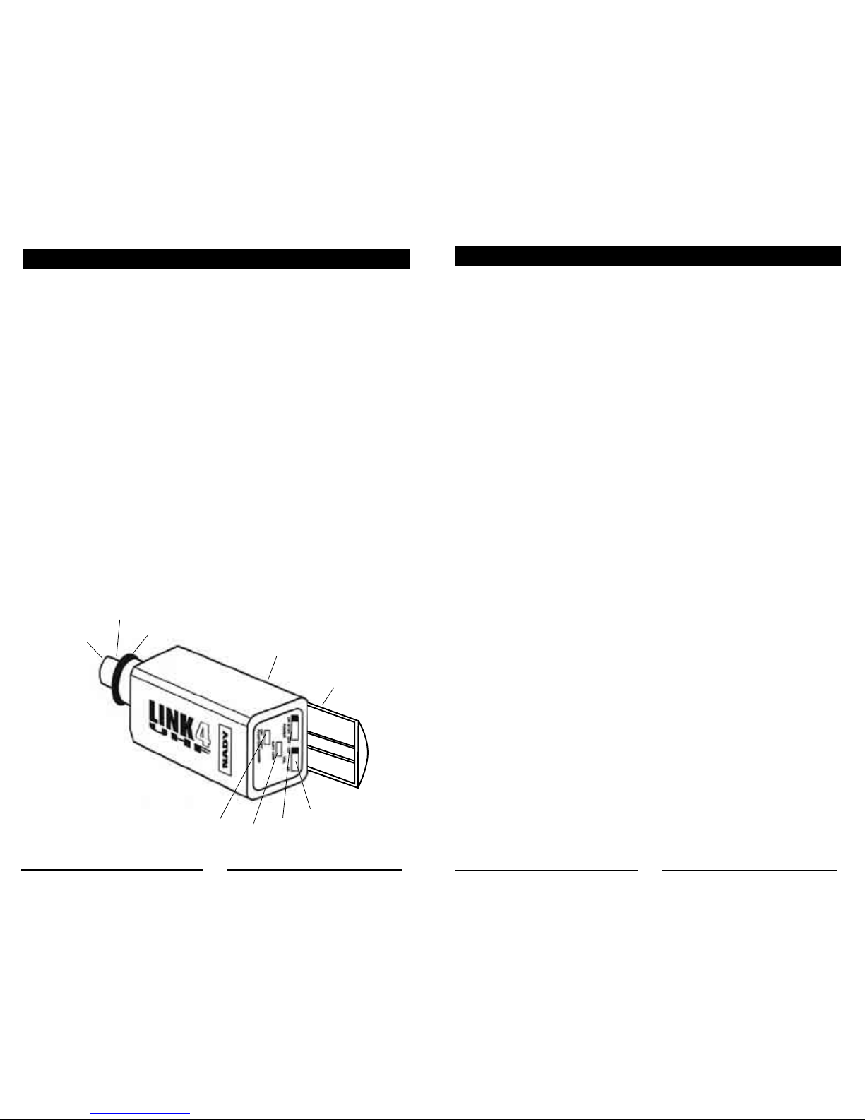
LINK 4™ Plug-In Transmitter
• Compact microphone transmitter that converts any dynamic XLR hardwired microphone to wireless operation
• OFF/MUTE/ON switch for ease of use
• Unique sliding battery compartment for quick pop-in battery replacement–uses standard 9V alkaline battery
• Single LED indicator flashes once for unit on; lights steady for low battery alert
• Audio LO/MED/HI gain selection for optimum sound
• Selectable 9V DC phantom powering for lavalier condenser microphone operation
• Standard locking 3-pin connector with adjustable threaded ring to provide secure connection to
any XLR handheld direct or to lavalier microphone cable
• Lightweight, ABS housing with integral antenna
Level Trim Adjust
For optimum performance, an INPUT SELECT SWITCH (44) is provided. You could select the
switch to LO/MED or HI gain setting defending to your microphone use. Depending on the average
distance between vocalist’s mouth and microphone, you can adjust the level for your application.
Factory setting is MED for hardwire dynamic microphone. This is a setting to be used in most typical close microphone applications. Set for maximum possible gain and headroom without noticeable distortion of the high level peaks. Experiment and set for maximum possible gain without
audible distortion on the high level peaks.
Receiver Volume Controls Adjust
The PA sound output level is control by the volume control MIC/TS knob. If feedback (howling
sound) occurs, try first turning own the TREBLE CONTROL (7). If feedback still is present, try turning down the VOLUME (6) or repositioning the WA-125U with respect to the wired or wireless mic
being used.
The bodypack transmitter is now ready to use. The RF ON indicator on the receiver should now
be on, indicating a received signal from the transmitter. When ready to speak, slide the OFF/
STANDBY/ON SWITCH (42) to the ON position. Adjust the volume of the receiver as outlined in the
Receiver Operating Instructions section: Operating the WA-125U.
Notes:
• Selecting LOW gain setting can compromise the signal-to-noise and it is not recommended.
• The microphone ball on your hardwire microphone functions as an integral antenna. For proper
operation, it should not be cover or touch during operation.
• Observe care in selecting P.A. volume, transmitter location and speaker placement so that acoustic feedback (howling or screeching) will be avoided.
LINK 4™ PLUG-IN TRANSMITTER
37
38
39
40
41
43
42
44
45
 Loading...