

Page 1
OWNER’S MANUAL
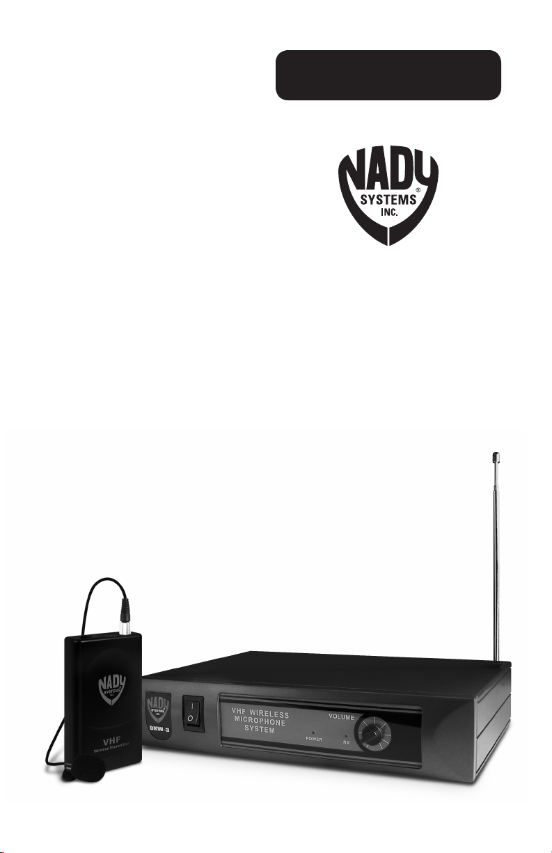
DKW-3 LT
Wireless VHF Microphone System
Page 2

Contents
Introduction .............................................................................................................................2
System Features ..................................................................................................................... 2
Operation ................................................................................................................................. 3
Specifications ..........................................................................................................................6
Service Information ................................................................................................................. 6
Warranty .................................................................................................................................. 7
Introduction
Thank you for choosing the Nady DKW-3 LT wireless microphone system, we know you
will be very pleased with its performance and features. The Nady DKW-3 LT is is loaded
with top professional operating features and is the best performance and price value
available in VHF wireless systems.
System Features
1
Receiver
All the advantages and freedom •
of wireless operation without
cumbersome cords
Easy to use—simply plug into your audio •
mixer or amplifier instead of your wired
lavalier/lapel microphone
Excellent high fidelity audio—perfect •
for public speaking, karaoke/recreational
singers, DJ’s, and many other applications
150+ feet typical operating range— •
up to 300+ feet line-of-sight
High-band VHF (170-216 MHz) operation •
for reliable, interference-free performance
Advanced audio processing circuitry for •
a wide dynamic range (no overloading
for loud inputs or background hiss during
quiet use)
Complete controls and connections for •
professional operation include front panel
power On/Off switch, output volume
control, Power On LED indicator
Back panel •
and DC power input jack for supplied
AC/DC adaptor
Special added circuitry eliminates •
transmitter On/Off “pop” noise
Collapsible receiver antenna•
WLT Bodypack Transmitter
Supplied with LM-14O omnidirectional •
lavalier/lapel microphone
Off/Standby/On switch allows convenient •
audio muting with the transmitter on
Low battery LED indicator flashes •
once for Unit On; lights steady for
low-battery alert
Locking 3.5mm mini-jack provides •
secure connection for removable
microphone cable
Easily accessible input level adjust •
control for optimum sound
/4” audio output jack
2
Page 3
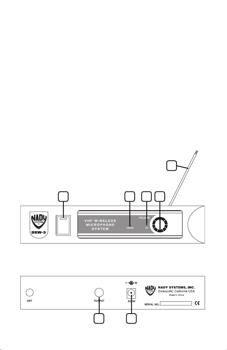
Operation
4
1 2 7 6
5 3
Receiver
1. Plug the AC/DC adapter (provided) into
the 9VDC INPUT JACK (3) on the back of the
receiver. Then plug the power supply into
an AC outlet. Switch the POWER (1) to the
“On” position. The POWER ON LED (2) will
now light and the receiver is operational.
2. Rotate and extend ANTENNA (4) fully,
angled at 60° position as shown.
1
/4” AUDIO OUTPUT JACK (5) provides
3. The
a fixed, unbalanced MIC level audio output
1
for connection to your mixer with the
1
/4” cord supplied. As when making any
to
/4”
connection, make sure the mixing board’s
volume is at the minimum level before
plugging in the receiver to avoid possible
sound system damage. Use the VOLUME
CONTROLS (6) to adjust the volume.
Note: this output is the sum of the signals received
by both the internal receivers (CH 1 + CH 2).
Use the CH 1 & CH 2 VOLUME CONTROLS (6)
to adjust the individual relative channel volumes.
3
Page 4

WLT Bodypack Transmitter
1. Snap open the BATTERY COMPARTMENT (7)
and insert a fresh 9V BATTERY (8), observing
the correct polarity. Close the compartment.
2. The WLT is provided with a 3.5 mm
LOCKING JACK (9) for connecting the
microphone. Plug in either the LAVALIER/
LAPEL (10) or the HEADWORN MICROPHONE
(11), as supplied. To secure the connection,
turn the metal slip ring on the plug
clockwise to thread it on to the jack. To
unplug, reverse the process. Slip the
transmitter into a pocket or clip on to your
clothes. To use the lavalier mic, attach it
at chest level. Do not place too close to
the mouth— a distance of about six inches
usually works best. To use the headworn
mic, place it on the head and adjust the mic
boom so that the mic is about one inch to
the side of the front of the mouth.
(Note: The lavalier or headworn mic wire is also the
transmit antenna, and rolling up or shortening the
wire may reduce the effective operating range.
Extend the wire fully during use, and keep it as
straight as possible.)
3. Turn on the WLT by sliding the OFF/
STANDBY/ON SWITCH (11) to the Standby
position (transmitter on, audio muted) or the
On position (transmitter and audio both on).
The BATTERY INDICATOR LED (12) will give a
single quick flash, indicating usable battery
strength. In the case of a dead or low
battery, the LED either will not go on at all or
will stay on continuously, indicating that the
battery should be replaced with a fresh one.
4. The microphone is now ready to use.
When ready to speak, slide the transmitter
switch to the On position and adjust the
volume of the receiver as per the previous
Receiver Operation section. For optimum
performance, an INPUT LEVEL CONTROL (13) is
provided on the top panel of the WLT. Adjust
the gain by turning the control with a small
slot head screwdriver. It is recommended
that this control be turned to maximum gain.
(Note: Turning down the input gain too much can
compromise the signal-to-noise ratio and is not
recommended. Set for the maximum possible
gain and headroom without noticeable distortion
on the high level peaks).
(Note: Observe care in selecting P.A. volume,
transmitter location and speaker placement so
that acoustic feedback (howling and screeching)
will be avoided. Please also observe the
pickup patterns of the microphone selected:
omnidirectional mics pick up sound equally from
all directions and are prone to feedback if not used
carefully. Unidirectional mics are more resistant
to feedback, but pick up sound sources best that
are directly in front of the mic. Also, mics that are
farther from the sound source, such as lavaliers,
require more acoustic gain and thus are also more
prone to feedback than close-source mics such as
handheld or headworn mics that are used close to
the mouth.)
(Note: Microphone elements can easily be
destroyed by the buildup of salts and minerals
from perspiration and saliva. It is good practice to
put a windscreen on the mic element at all times
to protect it.)
4
Page 5

OFF/STANDBY/ON
BAT
LOW
HI
MIC
11
12
13
9
10
Opening Battery Compartment
7
8
5
Page 6

Specifications
OVERALL SYSTEM PERFORMANCE
Frequency Response 80-14,000 Hz, +/-3dB
Dynamic Range 95dB
Total Harmonic Distortion <0.7%
RF Carrier Frequency Range 170-216 MHz
Frequency Stability +/- 0.005%, crystal controlled
Modulation FM (F3E), +/-15KHz max.
Operating Range 150 ft. typical— up to 300+ ft. line-of-sight
WLT TRANSMITTER
Audio Inputs 3.5mm mono locking jack for connecting to omnidirectional
Controls Off/Standby/On switch, input level adjust
LED Indicator Unit On (single flash), Low-Battery Alert (steady)
RF Power Out 50mW (Max. allowed by FCC)
Harmonic & Spurious Emissions > –40dB
Battery 9V Alkaline
Battery Life Up to 15 hours
Dimensions 4.1 x 2.4 x 0.8 in. (10.4 x 6.1 x 2.0 cm.)
Weight (w/o battery) 3.6 oz. (101 g.)
RECEIVER
Controls Power On/Off
Connectors
LED Indicator Power On, Transmitter RF (CH A & CH B)
Dimensions 8.2 x 5.3 x 1.75 in. (20.8 x 13.5 x 4.4 cm.)
Weight 16.1 oz. (451 g.)
Power Requirements 9V @ 120mA, nominal, AC/DC adapter supplied
Antenna Single 15 in. (38 cm.) collapsible
Specifications subject to change for product improvement purposes
lavalier/lapel mic, with phantom power
1
/4” unbalanced audio out jack, 2.1mm barrel-type DC input jack
Service Information
In the U.S. If you are experiencing operational problems with your system, please refer to
the Support page at www.nady.com for assistance. Should your wireless system require
service, please contact the Nady Service Department at (510) 652-2411 to obtain a Return
Authorization (R/A) Number and service quote (if out of warranty). Make sure the R/A
Number is clearly marked on the outside of the package that you are returning.
If your unit is out of warranty, please enclose a cashier’s check or money order (or pay
by credit card) per instructions by the Nady Service Department. Ship your unit prepaid
to: Nady Systems, Service Department, 6701 Shellmound Street, Emeryville, CA 94608.
Include a brief description of the problem you are experiencing. For service of a unit under
warranty, please follow the instructions in the following section.
Outside the U.S. For service or warranty matters please contact the Nady distributor in your
country through the dealer/store from which you purchased this product.
Do not attempt to service this unit yourself as
it can be dangerous and will also void the warranty.
6
Page 7

90-Days Limited Warranty
Nady Systems, Inc. warrants to the original consumer purchaser (U.S.A. only) that the unit is free from
any defects in material or workmanship for a period of 90 days from the date of original retail purchase.
If any such defect is discovered within the warranty period, Nady Systems, Inc. will repair or replace the
unit free of charge, subject to verification of the defect or malfunction upon return to Nady Systems.
Please do not return your Nady product to the store where it was purchased as Nady Systems handles
your warranty service directly. Communication with our Service Department is the most efficient means
of servicing your unit and we are dedicated to keeping you a satisfied customer.
To the extent permitted by law, any applicable implied warranties, including warranties of merchantability
and fitness are hereby limited to 90 days from the date of purchase. Consequential or incidental
damages resulting from a breach of any applicable express or implied warranties are hereby excluded.
This warranty is in lieu of all other agreements and warranties, general or special, express or implied
and no representative or person including a Nady dealer, agent, or employee is authorized to assume
for us any other liability in connection with the sale or use of this Nady Systems’ product.
Whereas some states do not allow limitations on how long implied warranties last, and do not allow
exclusion of incidental or consequential damages, the above limitations and exclusions may not apply
to you. This warranty gives you specific legal rights and you may also have other rights which may vary
from state to state.
This warranty is subject to the following conditions:
1) This system must have been purchased from an authorized Nady dealer and all warranty
service must be performed by Nady’s service department. Any service not performed by Nady
will automatically void this warranty.
2) Items not covered: physical damage resulting from improper handling of the unit in transit from the
factory by the shipper (Nady Systems is not responsible for such damage and all such claims must be
made against the shipping company by the consignee); defects caused by normal wear of the product
(expendable parts are typically connectors, cables, potentiometers, switches and similar components);
damage or defects caused by abuse, neglect, accident, failure to connect or operate the unit in any way
that does not comply with applicable technical or safety regulations, or improper repair, excessive heat
or humidity, alteration or unreasonable use of the unit, causing cracks, broken cases/housings or parts;
damage caused by leaking batteries; finish or appearance items; items damaged in shipment en route to
Nady Systems, Inc. for repair. The warranty is null and void if any Nady serial number has been removed
or defaced.
How To Obtain Service:
1) If factory service is required, please contact our Service Department at (510) 652-2411 for a return
authorization (R/A) number. Make sure the R/A number is clearly marked on the outside of your package.
(Please note: if an R/A number is not included, our Shipping Department cannot accept your package.)
2) Send the unit back to Nady Systems, 6701 Shellmound Street, Emeryville, CA, 94608, freight pre-paid.
You must include proof of date and place of purchase (i.e., photocopy of your bill of sale) or Nady cannot
be responsible for repair or replacement. Nady Systems, Inc. will not repair, nor be held responsible,
for any units returned without proper identification, return address, and R/A number clearly marked
on the package.
3) Per the above, Nady will perform all warranty service and return the unit to you at no charge.
Nady Systems will inform the buyer if product sent in does not meet the terms of this warranty
and will provide a quote for fixing the unit and/or shipping it back exclusively at the buyer’s expense.
7
Page 8

6701 Shellmound Street | Emeryville, CA USA 94608
T 510.652.2411 | F 510.652.5075 | www.nady.com
 Loading...