

Page 1
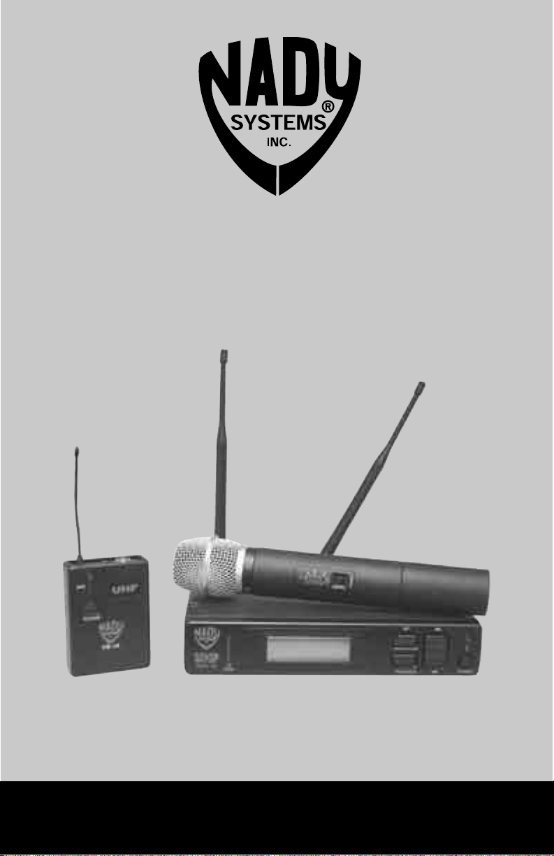
UWS-1K
1000 Channels PLL Frequency Synthesized
UHF Wireless Microphone and Instrument System
OWNE R’S MA NUAL
Page 2

TABLE OF CONTEN TS
INTRODUCTION � 3
USING THIS MANUAL ......................................................................................................................3
SYSTEM FEATURES .........................................................................................................................3
1. UWS-1K Receiver .................................................................................................................3
2. UH-1K and UB-1K Transmitters ............................................................................................ 3
SYSTEM OPERATION .......................................................................................................................4
3. UWS-1K Receiver Buttons Function .....................................................................................4
4. Selecting the UWS-1K Receiver Group, Channel, and SQL Setting .....................................4
5. UH/UB-1K Transmitters Buttons Function .............................................................................4
6. Selecting the UH/UB-1K Transmitters Group and Channel Setting ......................................5
UWS-1K RECEIVER ..........................................................................................................................5
7. Rack-mounting the Receiver ................................................................................................. 5
8. Installing Antennas ................................................................................................................ 5
9. Powering the Receiver ..........................................................................................................6
10. Adjusting the Mute (RF Squelch) ..........................................................................................6
11. Audio Level and Peak LED Indicator .....................................................................................6
12. Connecting the Audio Output ................................................................................................6
UH-1K HANDHELD TRANSMITTER ................................................................................................ 8
13. Setting up the Transmitter ..................................................................................................... 8
14. Powering the Transmitter ON/OFF ........................................................................................8
15. Programming the UH-1K with the Group/Channel Selected\on the Receiver ....................... 8
16. Operating the UH-1K Transmitter ..........................................................................................8
UB-1K BODYPACK TRANSMITTER ................................................................................................ 9
17. Setting up the Transmitter ..................................................................................................... 9
18. Powering the Transmitter ON/OFF ........................................................................................9
19. Programming the UB-1K with the Group/Channel Selected on the Receiver .....................10
20. Operating the UB-1K Transmitter ....................................................................................... 10
21. Instrument Use .................................................................................................................... 10
22. Microphone Use (with either a Lavalier or Headworn Microphone) .................................... 11
CAUTIONS AND TROUBLESHOOTING ........................................................................................12
23. Feedback .............................................................................................................................12
24. Microphone Damage ........................................................................................................... 12
25. No Audio ..............................................................................................................................12
26. RF Interference and Finding Open Channels ......................................................................12
TIPS ............� 13
SPECIFICATIONS ............................................................................................................................14
FREQUENCY PLAN ........................................................................................................................ 15
ACCESSORIES ...............................................................................................................................15
SERVICE INFORMATION ............................................................................................ BACK COVER
2
Page 3

INTRODUC TION
Thank you for choosing the Nady UWS-1K Series wireless system, and congratulations on your
choice. The Nady UWS-1K series systems are by far the best performance and price value in
professional UHF wireless. They offer clear channel operation on the wide-open, uncluttered UHF
band for interference-free performance in any application or locale. The UWS-1K series delivers 1000 user switchable channels, frequency synthesized in 24 groups and 40 channels in each
frequency band. Band-1 748-7773MHz, Band-2 795-820MHz, and Band-3 846.000-871MHz. The
UWS-1K Series system feature Nady’s proprietary companding and low noise circuit for an industry
best 120dB dynamic range, and the clearest, most natural sound available in wireless today.
USING THIS M ANUAL
This booklet gives instructions for the operation of the UWS-1K systems: UB-1K bodypack and
UH-1K handheld microphone transmitters, and UWS-1K receiver.
This manual will first explain the benefits of the UWS-1K and then will take you step by step on how
to operate your new system. Each section will give you detailed information. Also, included in this
manual are the system specifications and servicing information.
SYSTEM FEATURES
1. UWS-1K Receiver
• Unsurpassed UHF performance with 120dB dynamic range and operation up to 500 feet line-ofsight
• 1000 user switchable UHF frequencies per band
• Two complete front end True Diversity circuitry for eliminating dropouts and maximizing range
• Sophisticated IF filtering for multiple UWS-1K system operation in the same location
simultaneously
• Tone Squelch circuitry for protection from RF interference
• Front panel backlit LCD display indicates the selected channel/frequency, SQL level, receiver RF
level, A/B diversity status, transmitter battery level monitor and Audio LED bar graph for AF levels
• Front panel touch control buttons and user friendly configuration menus
• Download feature sends channel program to transmitter via IR sender
• Back panel balanced XLR mic level and unbalanced 1⁄4” jack audio outputs, and TNC jacks
for dual antennas (with 9VDC/100mA phantom power for powering optional remote powered
antennas as needed for longer antenna cable runs)
• Rack mountable with optional single or dual (side-by-side) rackmount kits
• Externally powered with 16.5V/0.4A DC adapter included
2. UH-1K and UB-1K Transmitters
• Choice of transmitters: UH-1K handheld or UB-1K bodypack, both 1000-channels selectable
• UH-1K handheld is a sleek, durable unit with an internal antenna system and the superior Nady
DM-10D neodymium cartridge for clear, powerful audio, and the powerful audio section provides
maximum feedback rejection, and minimal handling noise
• UB-1K bodypack is a versatile unit with a unique 4-pin Mini XLR input connector for instrument,
lavalier mic, or headworn mic (with convenient DC phantom powering)
• An input level control allows optimal audio gain adjustment (HM/LT mode only)
• UH-1K and UB-1K IR link features Infrared downloading of selected group/channel information
from receiver for easy channel programming
• UH-1K and UB-1K transmitters feature touch power ON/OFF and Mute control button, Low battery
status and Mute LED indicator
• UH-1K and UB-1K both operate on 2 AA batteries for the longest reliable and economical battery
life
3
Page 4

SYSTEM OPERATION
3. UWS-1K Receiver Buttons Function
Each time the Set Button (19) is pressed the LCD Menu (10) display will cycle through the set up
menus in this order: MAIN MENU->CHANNEL->GROUP->SQL->MAIN MENU and then repeat.
The selected function will flash for 20 seconds before returning to the MAIN MENU. To exit from any
setting menus, press Transfer Button (18) once.
When pressing the Transfer Button (18) once while MAIN MENU is displayed, the Power LED (9)
will flash quickly. This LED indicates IR transmission is in progress. Press Transfer Button (18)
again to stop or it will expire in 20 seconds automatically.
The UP-DOWN Rocker button (20) works only while setting the menu. At Power OFF the UWS-1K
receiver will store the last settings entered and re-display them at Power ON. It can be reprogrammed to any new group/channel, and SQL level. The default factory setting is Group 13, Chan-
nel 01, and SQL 01.
4. Selecting the UWS-1K Receiver Group, Channel,
& SQL Setting
See Section 26 below (RF Interference and Finding Open Channels) also for help in finding desired
channel(s) of operation in setting up your system(s).
Choose the UWS-1K operating frequency by selecting one of 25 Groups and one of 40 Channels
in each group that are determined to be desirable open channels as per the procedure outlined
in Section 26. The first two large digits on the left are the GROUP (11) and the second two large
digits on the right are for the CHANNEL (11). Press the Set Button (19) once to enter the CHAN-
NEL (11) set up mode and then press the UP-DOWN Rocker button (20) once for single stepping
through the channels or hold continuously for faster channel selection. Select one of 40 channels
available from the CHANNEL (11) menu and advance to GROUP (11) set up mode by pressing Set
Button (19) or press Transfer Button (18) to exit.
Press the Set Button (19) again to enter the GROUP (11) set up mode and then press the UP-
DOWN Rocker button (20) once for single stepping through the groups or hold continuously for
faster group selection. Select one out of 25 groups from the GROUP (11) menu and advance to
SQL (14) set up mode by pressing Set Button (19) or press Transfer Button (18) to exit.
Press the Set Button (19) once to enter the SQL (14) set up mode and then press the UP-DOWN
Rocker button (20) once for single stepping through the SQL (RF muting/squelching) levels or
hold continuously for faster SQL level selection. Select one out of 50 levels from the SQL menu and
advance to Exit set up mode by pressing Set Button (19) or press Transfer (18) to exit.
Press Set Button (19) once to exit or press Set (19) twice to restart selection of a different channel, group, or SQL level. When the exit mode is reached, the new group/channel/SQL selected are
programmed.
5. UH/UB-1K Transmitters Buttons Function
Press the Power Button (23/32) for more than 2 seconds to power up the transmitter (please also
see section 14 & 18 below). It will now be in standby (audio input muted) mode. Press the Power
Button (23/32) again briefly to unmute or to mute the audio.
4
Page 5

SYSTEM OPERATION
6. Selecting the UH/UB-1K Transmitters Group &
Channel Setting
Both the UH/UB-1K transmitters have to be programmed for the channel and group selected on
the UWS-1K receiver via the IR reception link between the receiver and transmitter during the first
20 seconds after the transmitter is powered up. As soon as the transmitter LEDs light up indicating Power ON, the Transfer Button (18) on the UWS-1K receiver must be pressed once while the
MAIN MENU is being displayed. The Power LED (9) of the receiver will flash quickly indicating IR
transmission to the transmitters of the Group and Channels selected on the receiver is in progress.
Successful transfer is complete when the Signal Strength indicator on the receiver’s LCD Display
(10) indicates a received signal from the transmitter being programmed. Press Transfer (18) again
to stop when this happens or just let it expire in 20 seconds automatically. (Important note: there is
no other way to program the Group and Channel selected in the UWS-1K receiver into the UH/UB1K transmitters so the above procedure must be followed carefully.)
UWS-1 K RECEI VER
7. Rack-mounting the Receiver
There are two options available for rackmounting the UWS-1K: single or side-by-side with another
UWS-1K receiver.
a. Single mounting: Just attach the optional Rack Ears (1) to each side slot and tighten with
supplied screws (as shown).
b. Side-by-side mounting: Attach the two optional Join Pieces (2) and tighten the four supplied
screws. Then attach the rack ears to each side slot and tighten with supplied screws (as
shown).
(Note: Do not mount the receiver on a rack directly above an amplifier or other source of high heat.
This could degrade the performance of the UWS-1K. Always ensure adequate airflow and heat dis-
sipation in any rack configuration.)
8. Installing Antennas
Install antennas by connecting the two Antennas (3) included with your system to the two RF
Screw-On Connectors (4) located on the back of your UWS-1K receiver. The optimal positions
of the antennas are 45 degrees from the receiver and 90 degree from each other. For maximum
range, it is always best to maintain a line of sight (no obstructions) between the receiver antennas
ant the transmitter at all time whenever possible.
9. Powering the Receiver
To power the receiver, plug the AD-DC adaptor (16.5VDC/0.4A) provided into the DC Input Jack
(5) on the back of the receiver. Then plug the adapter into an AC outlet. (Note: Any 16.5VDC source
with 400mA capacity can also be used.) Connect either the XLR Balanced (6) or 1⁄4” Unbalanced
Output (7) to your mixing board, effect, or amplifier.
To turn ON, press the Power Switch (8) for 2 second. The Power LED (9) will light and the LCD
Display (10) will show the Group (11), Channel (11) assignment, RF Level Meter (12), Diversity
(13), and the audio AF LED (15) displays (when the transmitter is activated).
To turn OFF, press the Power Switch (8) for 3 seconds and release. The receiver will turn off.
5
Page 6

UWS-1 K RECEI VER
10. Adjusting the Mute (RF Squelch)
The Mute (RF squelch) (14) controls both the A and B receiver channels. This control ranges from
01 (low mute sensitivity level) to 50, (high mute sensitivity level). The control should be adjusted
up to the highest reading at which the RF Level Meter (12) and the Diversity Indicator (13) will
remain on while your transmitter is in normal use, up to the maximum operating range anticipated in
use. However, in areas of high RF activity, the mute may need to be adjusted. If the transmitter is
off and the receiver signal and the diversity indicator are flickering or stay on continuously, the mute
should be adjusted down to a lower reading (less sensitivity level) to stop the flickering. Be careful
not to select too low a reading as that will reduce the operating range below what is needed. A
range walk test will help in selecting the proper level needed. If the range is not critical, note that a
lower reading will also yield a quieter mute function, which might be desired in certain applications.
The mute level is factory preset at 50 for maximum sensitivity and operating range.
11. Audio Level and Peak LED Indicator
The UWS-1K receiver is equipped with a 5-segment AF LEVEL LED (15) display that lights up
sequentially indicating the level of the audio signal from the transmitter. Occasional flickering of the
top (red) Peak LED on loud inputs to the transmitter is normal. If the Peak LED lights continuously,
decrease the volume to the transmitter or overload distortion may result.
12. Connecting the Audio Output
The UWS-1K audio output is set up for either balanced (fixed level) or unbalanced line (adjustable
level). The output is controlled by the Volume Control (16).
For balanced output with either a handheld mic or lavalier bodypack transmitter, plug an audio
cable with an XLR connector into the Balanced Output socket and plug the other end into your
amplifier or mixing board. For unbalanced output with either a handheld mic or lavalier bodypack
transmitter, plug an audio cable with a 1⁄4” mono plug into the (AUX) line out and plug the other
end into your amplifier or mixing board. For an instrument transmitter system, use the (AUX) output
connects directly to your own system. The system output is approximately +4dB higher than a direct
cord-to-amp connection.
(Note: As when making any connection, make sure the amplifier or mixing board volume is at the
minimum level before plugging in the receiver to avoid possible sound system damage.)
Your UWS-1K is now operational and ready to use. Now that you have completed the above step,
proceed to instructions for the UH-1K or UB-1K transmitter included with your system. (Please note:
Only one transmitter can be used with one UWS-1K receiver. It is not possible too use two transmitters on the same frequency and mix the output of these transmitters into one wireless receiver.)
6
Page 7

UWS-1 K RECEI VER
2
1
1
17
15
13 121413
1. Rack ears (optional)
2. Join pieces (optional)
3. Antennas
4. RF screw-on connectors
5. DC input jacks
6. XLR balanced output
7. 1/4” unbalanced output
8. Power switch
9. Power LED
10. Menu display
11
10
19
18
20
9
8
5
3
11. Group/Channel
12. RF level meter
13. Diversity indicator
14. RF squelch (MUTE)
15. AF LED display
16. Volume control
17. IR transmitter
18 Transfer
19. Set
20. UP-Down button
6
16
7
4
7
Page 8

UH-1K HANDHELD MICROPHONE TRANSMITTER
13. Setting up the Transmitter
The UH-1K requires 2x AA size batteries to operate. To install the batteries onto the Battery Holder
(21), unscrew the Battery Cover (22) by turning counter-clockwise and remove the cover, expos-
ing the battery holder. Insert 2 fresh AA batteries according to the correct polarity as indicated on
the transmitter body. Screw cover back onto the microphone. Make sure the cover is screwed on
completely. Fresh Alkaline batteries can last for up to 8-10 hour of operation, but in order to ensure
optimum performance, it is recommended that the batteries be replaced after 6-8 hours of use.
14. Powering the Transmitter ON/OFF
To turn transmitter on, press and hold the Power/Mute Button (23) for more than 2 seconds. All the
4 LEDs (IR, Mute ON, and two battery strength indicators) will light up. The unit is now on. After 20
seconds the IR LED Indicator (25) will automatically turn off. The Mute LED (26) will stay lit only if
the audio mute is ON (audio signal off). The two Battery-Level LEDs (27) should stay fully lit green
indicating usable battery strength. If the batteries are weakening, only one will stay lit green. This
Battery-Level LED (27) turns red if the batteries are low and the batteries should be replaced with
new ones. To preserve battery life, turn the transmitter off when not in use. To turn the transmitter
off when on, press and hold the Power/Mute Button (23) again for more than 2 seconds. No LEDs
will light up and the unit will be off.
15. Programming the UH-1K with the Group/Channel Selected on
the Receiver
Channel selection on the transmitter is done using the wireless IR LED Sensor (24) link to download preprogrammed channels from the receiver (see also sections 4 and 6 above). Immediately
upon being powered on, the unit will be in IR standby, which means it is accepting data previously
set up for the receiver. Start programming by aiming the IR LED Sensor (24) on the transmitter
from about 6” away to the IR Transmitter (17) on the receive and then press the Transfer But-
ton (18). The Power LED (9) starts flashing for 20 seconds that indicates IR transmission is in
progress. Upon successful data transfer (usually in less then 2 seconds) the transmitter’s IR LED
Indicator (25) will be turned off and the transmitter will transmit a radio signal on the same channel
as the receiver and the Signal Strength (12) and Diversity Indicators (13) on the receiver will
then start indicating that the IR link is completed. If no action is taken during 20 seconds, the unit
goes into audio standby (audio mute) mode and the previous program channel remains unchanged.
After 20 seconds the IR LED (on both the UWS-1K and UH-1K) will turn off.
(Note: The IR link is infrared light and thus works best when this data transfer is accomplished in
a light-shielded or darker environment. It may not be successful in a brightly lit area. If the transfer fails, repeat the procedure in a darker location or somehow shield the link from outside light
to successfully program the transmitter with the preprogrammed group and channel info from the
receiver.)
16. Operating the UH-1K Transmitter
The Power/Mute Button (23) functions both as a power and as an audio mute on/off switch. After
the units is powered on, press the Power/Mute Button (23) once quickly to unmute the audio. The
Mute LED (26) will turn off and you can speak. To mute/unmute in succession, press the Power/
Mute Button (23) again as needed.
For optimum performance, an Input Level Control (28) is provided. Adjust the gain by turning the
control with a small screwdriver. It is recommended that the level be set at about 1⁄2 maximum.
Experiment and set for maximum possible gain without audible distortion on the high level peaks.
(Note: Turning down the gain too much can compromise the signal-to-noise and is not recommended.)
The microphone is now ready to use. The receiver’s signal strength and diversity indicators should
now be on, indicating a received signal from the transmitter. When ready to speak, press the
8
Page 9

UH-1K HANDHELD MICROPHONE TRANSMITTER
UH-1K’s POWER button to unmute. To mute, press the Power/Mute button again. Adjust the volume of the receiver as per section 12 (UWS-1K Receiver: Connecting Audio Output).
[Note: Observe care in selecting P.A. volume, transmitter location and speaker placement so that
acoustic feedback (howling or screeching) will be avoided.]
[Note: The RF Level Meter (12) and the Diversity Indicator (13) on the receiver are “ON” in
normal use with the audio “ON” (not muted). When the transmitter is “ON” but muted, the RF Level
Meter will stay “ON” but the Diversity Indicator wil be “OFF”.]
(Note: The 2 AA batteries loaded into the bottom half of the UH-1K function as a built-in antenna.
For proper operation and best operating range the transmitter should be held above that area so as
not to hand block the antenna and lessen the transmission strength.)
25
28
23
24
27
21
22
26
21. Battery holder
22. Battery cover
23. Power/Mute button
24. IR LED sensor
25. IR LED indicator
26. Mute LED
27. Battery level LEDs
28. Input level control
UB-1K BODYPACK MICROPHONE TRANSMITTER
17. Setting up the Transmitter
The UH-1K requires 2x AA size batteries to operate. To install the batteries onto the Battery
Holder (30), press the “OPEN” side on the Battery Lid (29) and slide as indicated by the arrow
to open the Battery Lid (29), exposing the battery holder. Insert 2 fresh AA batteries according to
the correct polarity as indicated on the transmitter body. Cover the Battery Lid (29) and press on
the “CLOSE” side slide as indicated by the arrow to lock the battery door securely. Fresh Alkaline
batteries can last for up to 8-10 hour of operation, but in order to ensure optimum performance, it is
recommended that the batteries be replaced after 6-8 hours of use.
18. Powering the Transmitter ON/OFF
To turn transmitter on, press and hold the Power/Mute Button (32) for more than 2 seconds. Both
LEDs IR/Audio Mute (34) and Battery Strength Indicator (33) will light up. The unit is now on. Af-
ter 20 seconds the green IR LED (34) will automatically turn off. If the audio is muted (see Section
20 below) the LED will stay lit and change to red till the audio mute is turned off (and audio signal is
9
Page 10

UB-1K BODYPACK MICROPHONE TRANSMITTER
back on). The Battery Level LED (33) should stay fully lit green indicating usable battery strength.
This LED turns red if the batteries are low and the batteries should be replaced with new ones. To
preserve battery life, turn the transmitter off when not in use.
To turn the transmitter off when on, press and hold the Power/Mute Button (32) again for more
than 2 seconds. No LEDs will light up and the unit will be off.
19. Programming the UB-1K with the Group/Channel Selected on
the Receiver
Channel selection on the transmitter is done using the wireless IR (infrared) link to download preprogrammed channels from the receiver (see also sections 4 and 6 above). Immediately upon being
powered on, the unit will be in IR standby, which means it is accepting data previously set up for the
receiver. Start programming by aiming the IR Sensor (36) on the transmitter from about 6” away to
the IR Transmitter (17) on the receive and then press the Transfer Button (18). The Power LED
(9) starts flashing for 20 seconds that indicates IR Transmission (17) is in progress. Upon successful data transfer (usually in less then 2 seconds) the transmitter’s IR LED (34) will be turned off
and the transmitter will transmit a radio signal on the same channel as the receiver and the Signal
Strength (12) and Diversity Indicators (13) on the receiver will then start indicating that the IR link
is completed. If no action is taken during 20 seconds, the unit goes into audio standby (audio mute)
mode and the previous program channel remains unchanged. After 20 seconds the IR LED (34) (on
both the UWS-1K and UB-1K) will turn off.
(Note: The IR link is infrared light and thus works best when this data transfer is accomplished in
a light-shielded or darker environment. It may not be successful in a brightly lit area. If the transfer fails, repeat the procedure in a darker location or somehow shield the link from outside light
to successfully program the transmitter with the preprogrammed group and channel info from the
receiver).
20. Operating the UB-1K Transmitter
The POWER button functions both as a power and as an audio mute on/off switch. After the units
is powered on, press the Power/Mute Button (32) once quickly to unmute the audio. The Mute
LED (33) will turn off allowing audio signal input (speech or from instrument). To mute/unmute in
succession, press the Power/Mute Button (32) again as needed.
For optimum performance, an Input Level Control (31) is provided (lavalier or headworn mic
modes only). Adjust the gain by turning the control with a small screwdriver. It is recommended
that the level be set at about 1⁄2 maximum. Experiment and set for maximum possible gain without
audible distortion on the high level peaks.
(Note: Turning down the gain too much can compromise the signal-to-noise and is not recommended.)
The transmitter is now ready to use. The receiver’s signal strength and the diversity indicators
should now be on, indicating a received signal from the transmitter. When ready to transmit audio,
press the UB-1K’s Power/Mute Button (32) to unmute. To mute, press the POWER button again.
Adjust the volume of the receiver as per section 12 (UWS-1K Receiver: Connecting Audio Output)
above.
[Note: When using in lavalier or headworn mic input mode, observe care in selecting P.A. volume,
transmitter location and speaker placement so that acoustic feedback (howling or screeching) will
be avoided.]
21. Instrument Use
Secure the connection of the GT (instrument) cable by lining up the slot of the mini XLR connector and pushing in to lock in. When ready to play, press the POWER button once momentarily to
10
Page 11

UB-1K BODYPACK MICROPHONE TRANSMITTER
unmute the transmitter audio. Adjust the volume on the receiver for one-to-one, unity gain with a
hardwired cord or select up to an added 4-5dB boost by adjusting the receiver volume to maximum.
(Note: The input level control is deactivated and not used when the UB-1K is in instrument mode.
The level should be adjusted on the instrument as when using a hard-wired cord.)
22. Microphone Use (with either a Lavalier or Headworn
Microphone)
Secure the connection of the LT (headworn or lavalier mic) cable by lining up the slot of the mini
XLR connector and pushing in to lock in.
When ready to play, press the Power/Mute Button (32) once momentarily to unmute the transmitter audio. To use the lavalier mic, attach it at chest level. Do not place it too close to the mouth—a
distance of about six inches usually works best. To use the headworn mic, place it on the head and
adjust the boom so that the mic is about one inch to the side of the front of the mouth. When ready
to use, press the Power/Mute Button (32) once momentarily to unmute the transmitter audio.
For optimum performance, an input level control in provided. Adjust the gain by turning the control
with a small screwdriver. For lavalier mic use, it is recommended that the level be set about 2/3
maximum. For headworn use, it may be advisable to turn the gain down somewhat, depending on
the volume levels expected. In either application, experiment and set for maximum possible gain
without audible distortion on the high level peaks.
[Note: The RF Level Meter (12) and the Diversity Indicator (13) on the receiver are “ON” in
normal use with the audio “ON” (not muted). When the transmitter is “ON” but muted, the RF Level
Meter will stay “ON” but the Diversity Indicator wil be “OFF”.]
(Note: Tuning down the gain too much can compromise the signal-to-noise and is not
recommended.)
34
37
29. Battery lid
30. Battery holder
31. Input level control
32. Power/Mute button
33. Battery level LED
34. IR LED indicator/mute LED
35. Mini XLR inputs
36. IR LED sensor
37. Wire antenna
38. Belt clip
31
29
32
33
11
30
36
35
38
Page 12

CAUTIONS AND TROUBLESHOOTING
23. Feedback
Observe care in selecting P.A. volume, transmitter location and speaker placement so that the
acoustic feedback (howling and screeching) will be avoided. Please also note the pickup pattern
characteristics of the microphone selected. Omni directional mics pick up sound equally from all
direction, and are prone to feedback if not used carefully. Unidirectional mics are more resistant to
feedback. However, they pick up sound sources best that are directly in front of the mic. Also mics
that are farther from the sound source, such as lavalier mics, required more acoustic gain and thus
are also more prone to feed back than close-source mics such as handheld or headworn models
that are used close to the mouth.
24. Microphone Damage
Headset and lavalier mic users: please note that the microphone element can easily be destroyed
by the buildup of salts and minerals from perspiration and saliva. It is good practice to put a windscreen on the mic at all time to protect it and to keep it clean and dry at all times.
25. No Audio
If you are not getting audio through the system, carefully re-check all setups. Especially note that
the receiver and transmitter must be set to operate on the same RF channel. Also confirm that the
Audio Mute on the transmitter is in the Off position.
26. RF Interference and Finding Open Channels
If you encounter slight receiving interference when the transmitter is far from the receiver (from
other than an operating TV station), often it can be overcome by adjusting the receiver ‘s squelch
control (SQL).
If receiving interference on a selected channel with the transmitter off, you must reprogram the
receiver and transmitter to a different channel (see sections 4, 6, 15, & 19). To reprogram, you must
first find an open channel. To do this follow the operating procedure outlined in Section 4 above,
and with the associated transmitter off, scroll through the groups/channels to find one that shows no
received signal on the receiver LCD display’s received signal icon (no bars). Also there must be no
bars either on each of the three immediately adjacent channels both below and above the selected
channel for optimum interference-free operation (so field of 7 adjacent channel total—with channel
used in the middle). If operating multiple UWS-1K systems simultaneously, repeat this procedure
with every new channel being selected, with previously tuned systems all ON, both transmitters and
receivers.
Please note that wireless frequencies are shared with other radio services. According to FCC
regulations, wireless microphone operations are unprotected from interference from other licensed
operations in the band. If any interference is received by any Government or non-government
operation, the wireless microphone must be cease operation or change frequencies. The above
statement is valid only for use in the U.S.A.
12
Page 13

TIPS
• For optimum operation with external antennas, low loss RF shielded cable should be used and the
length of the cable should not exceed 3m.
• The receiver antennas should be kept away from any metal surfaces whenever possible as they
can reflect or shield from the incoming RF signal.
• If the Volume Control of the receiver is set too high, it may over-drive the input of the attached
audio mixer, causing distortion. Conversely, if the output is set too low, the overall signal-to-noise
ratio of the system may be reduced, causing noticeable hiss. If such noise occurs, adjust the
output level of the receiver such that highest sound pressure level going into the microphone
transmitter causes no input overload in the mixer, and yet permit the mixer level control to operate
in the normal range (not too high and not too low). This provides the optimum signal-to-noise for
the entire system.
• Before inserting the batteries, please make sure that they are inserted with the correct polarity.
• Before operation please confirm that the receiver and associated transmitter are tuned to the
same frequency group and channel number.
• After making a receiver channel change, please make sure that the corresponding change is also
made on the matching transmitter (per Sections 15 & 19).
• Use only brand new alkaline batteries. Do not use “general purpose” batteries. When batteries are
weak, replace the batteries altogether at the same time. Do not mix and use new and old batteries
together.
• Position the receiver such that it has the least possible obstructions between it and the transmitter.
Line of sight is best!
• During operation, the transmitter and the receiver should be as close as possible for optimum
results but never closer than 3’ (1 meter).
• For the best operation, the receiver should be placed at least 1 meter above the ground and 1
meter away from a wall or metal surfaces. The transmitter should be also at least 1 meter from the
receiver. Keep antenna away from noise source such as motors, automobiles, neon light, signal
processor, computer, as well as large metal objects.
• A receiver cannot receive signal from two or more transmitters simultaneously.
• Turn the transmitter off when it is not in use. For longest life, remove the batteries if it is not to be
used for a long period (>1 year) as the transmitters draw a tiny residual current even when off to
maintain the programmed settings. Also, since batteries installed for a long time can sometimes
corrode and/or leak, causing damage, it is generally recommend that batteries be removed anytime the transmitters are not being used.
• When using the UB-1K for instrument use: (Note: Scratchy noises can sometime occurs when
some electric guitars with dirty pots or connections are used with any wireless system. Therefore,
the supplied capacitor provides first order filtering of the RF signal from the cord into the guitar
and eliminates virtually all scratchy noises. Should your equipment still give you scratchy noises,
we suggest these steps to eliminate them:
a. Make sure all guitar volume and tone pots are clean and all contacts are solid-this is
very important.
b. A 47pF capacitor soldered across the pot to ground terminal of the guitar’s volume and
tone pots will provide extra filtering.
13
Page 14

SPECIFICATIONS
SYSTEM SPECIFICATION
Operating Frequency Range ....................................................................760MHz-864MHz (3 bands)
Freq. Synthesized ................................................................... PLL system 1000 channels switchable
25kHz/step, frequency stability <0.005%
Frequency Response .............................................................................................. 30Hz-18kHz -3dB
Dynamic Range ......................................................................................................................... 120dB
Harmonic Distortion ....................................................................................................................<0.5%
Modulation ................................................................................... FM +/-25kHz normal, +/-75kHz max
Operating Range ............................................................. 250 feet normal, 500+feet max line-of-sight
RECEIVER SPECIFICATIONS
Receiver System ..............................................Dual conversion superheterodyne with True Diversity
(2 complete receiver sections with optimum audio selected)
Sensitivity ................................................................................................................. -107dBm, normal
Selectivity .............................................................................................. 60dB, normal +/-75kHz offset
Image Rejection .........................................................................................................-70dB, minimum
Spurious Rejection ......................................................................................................... 65dB, normal
Mute Threshold .................................................................... -65dBm to -95dBm (adjustable 50 steps)
Controls ..........................................................Channel/group/mute Up-Down selects, SET, IR Power
ON/OFF buttons, and audio level control
LCD Display .................................................... Single backlight LCD panel indicating Channel/Group
selected, received RF, A/B diversity
Power Requirement ............................................................................................................ 16.5V/0.4A
Antennas .......................................................................Dual TNC right angle or external remote with
9VDC/100 mA phantom power for optional remote powered antennas
Dimensions 8.625” x 5.875” x 1.625” (21.9 cm x 14.9 cm x 4.13 cm) [W / D / H]
Weight ................................................................................................................... 1.90 lbs (0.857 Kg)
TRANSMITTER SPECIFICATIONS
Models Available ...................................................... UH-1K Handheld, UB-1K Bodypack transmitters
RF Output Power ..........................................................................................+14dBm (25mW normal),
+17dBm (50mW maximum allowed by FCC)
Harmonic and spurious Emission ................................................................................. -50dBc normal
Audio Output Level .................................................................. Unbalanced output: 360mV adjustable
Audio Output Balanced ............................................................................................. 24mV fixed level
Audio Output Impedance ..........................................................Balanced and unbalanced: 600 Ohms
Controls .................................................................... Power ON/OFF switch, Audio Input level control
Audio Input Levels ........................ UH-1K: 24mV; UB-1K: 225mV (Instr.), 310mV (HM), 75mV (Lav.)
Impedance ......................................... UH-1K: 6.0k Ohms; UB-1K: 500k (Instr.), 2k Ohms (HM/Lav.)
Controls .......................... UH-1K: Power ON/OFF/Mute button; UB-1K: Power ON/OFF/Mute button
Connector ............................................................... UB-1K: 4-Pin Mini XLR input for Lav., HM or GT
LED Indicator .................................................................... UH/UB-1K: steady GREEN: Power, IR ON
UH/UB-1K: steady RED: Battery Alert, Mute ON
Antenna Type ................................................ UH-1K: Integral; UB-1K: External permanent attached
Battery Type ................................................................................................................. 2 X AA alkaline
Battery Life .............................................................................................................8-10 Hours normal
Dimensions ............................................................ UH-1K: 9.5” x 1.5” (24.13 cm x 3.81 cm) [L / Dia.]
UB-1K 1.375” x 3.25” x 0.875” (3.49 cm x 8.26 cm x 2.18 cm) [W / D / H]
Weight (w/o batteries) ...................................................................................UH-1K: 6.6 oz (0.187 kg)
UB-1K: 2.8 oz (0.08 kg)
14
Page 15

FREQUENCY PLAN
Band-1 748.900-773.875MHz 25kHz per step (1000 Channels) U.S.
Band-2 795.000-820.000MHz 25kHz per step (1000 Channels) U.S./ Europe
Band-3 846.000-871.000MHz 25kHz per step (1000 Channels) Europe
ACCESSORIES
Part Number Description
RMK-1K Single receiver rack mount kit
RMK-1KX2 Dual (side-by-side) receiver rack mount kit
IC-U1K Instrument cable for UB-1K transmitter, 4-pin mini-XLR to 1⁄4”
LM-14O/1K Omnidirectional lavalier mic with 4-pin mini-XLR
LM-14U/1K Unidirectional lavalier mic with 4-pin mini-XLR
HM-3/1K Unidirectional headworn mic with 4-pin mini-XLR
HM-1/1K Unidirectional headworn mic with 4-pin mini-XLR
AC-UWS1K 16.5VDC/400mA AC/DC receiver power supply adapter
15
Page 16

SERVICE INFORMATION
(U.S.) If you are experiencing operation problem with your system, check out the support
page on the Nady website: www.nady.com for help and for contacting the Nady Service
Department. Should your wireless System require service, you must contact the Nady Service
Department at (510) 652-2411 for a Return Authorization (R/A) Number and a service quote
(if out of warranty). Make sure the R/A Number is clearly marked on the outside of the package. Cashier’s check or money is enclosed (If not prepaid with credit card), and ship the unit
prepaid to: Nady System Inc., Service Department, 6701 Shellmound Street, Emeryville, CA
94608. Include a brief description of the problem you are experiencing, for service of a unit
under warranty follow the instruction of your Warranty Card regarding Warranty Service.
(International) For service, please contact the NADY distributors in your country through the
dealer from whom you purchase this product.
DO NOT ATTEMPT TO SERVICE THIS UNIT YUORSELF, AS THAT WILL VOID YOUR
WARRANTY.
NADY SYSTEMS, INC.
6701 Shellmound Street • Emeryville, CA 94608
Tel: 510.652.2411 • Fax: 510.652.5075 • www.nady.com
 Loading...