

Page 1
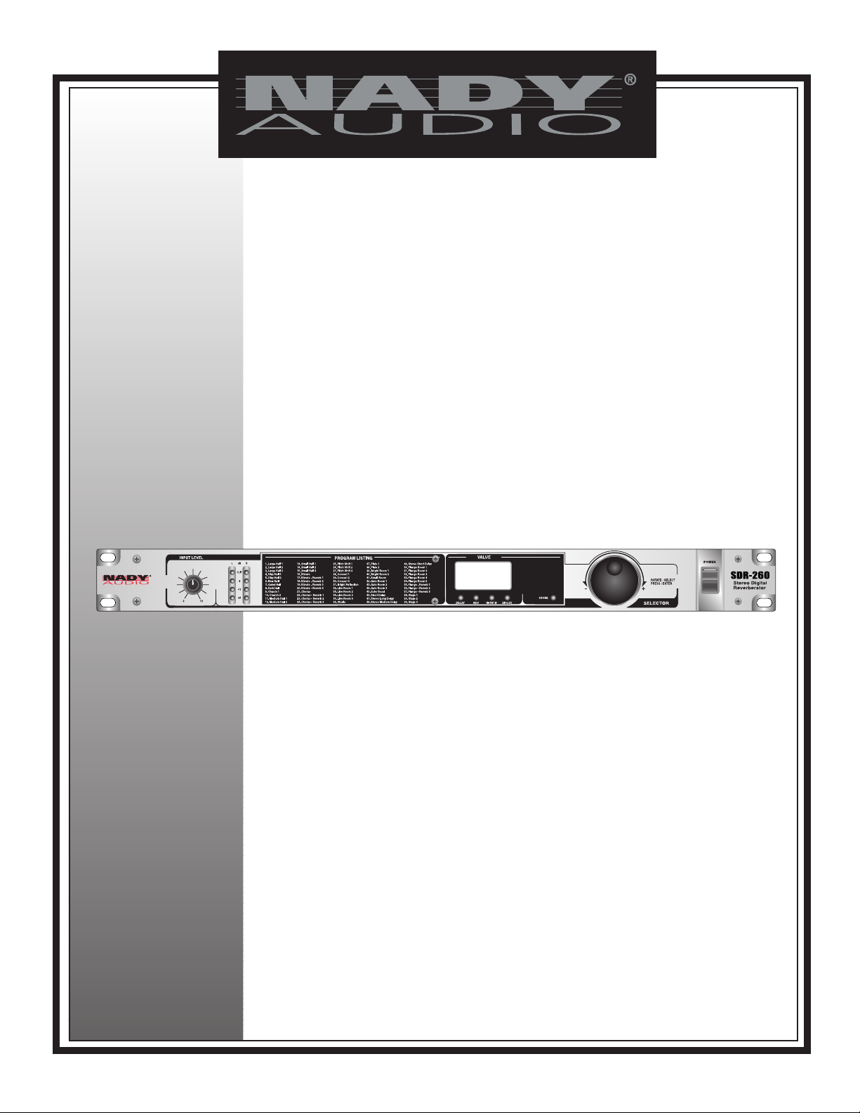
SDR-260
STEREO DIGITAL REVERBERATOR
OWNER’S MANUAL
EFFECT PROCESSOR
Page 2
2
SDR-260
Stereo Digital Reverberator
Congratulations on your choice of digital effects processor — you have purchased one of the finest digital effects processors
on the market today. This unit was developed using the expertise of professional sound engineers and working musicians. You
will find that your new NADY AUDIO SDR-260 has superior performance and greater flexibility than any other digital effects
processors in its price range. Please read this manual carefully to get the most out of your new unit.
Thanks for selecting NADY AUDIO as your choice in digital effects processor.
Date of Purchase
Dealer’s Name
City
State
Zip
Model #
Serial #
CONTENTS
FEATURES
An indispensable ally in numerous studio and stage applications, the versatile SDR-260 enables boundless creativity
with its richly textured, complexly detailed algorithms.
• Powerful dual engine digital sound processor (DSP) offers a
full complement of 60 of the latest and most useful breathtaking effects presets including hall and room reverbs,
gates, echo/vibrato/chorus/flanging delays, pitch shifting,
and concert/stage recreations.
• Intuitive and easy to operate-all parameters can be selected
and/or edited via the jog wheel knob or external MIDI
remote control (via Program Change messages) with 60
user program locations for personal edits storage
• 24 bit A/D and D/Aconverters for ultra-high headroom and
resolution. Internal 44.1 KHz sampling rate for unsurpassed
audio
• Servo-balanced inputs and outputs with XLR and 1/4” TRS
connectors.
• Input and output Level Switches add +4 dB or attenuation 10 dB.
• Remote MIDI program change and bypass control
• 4 segment ultra-precise stereo input level LED display
• 3 Digit program and parameter LED display
• Front Panel Selectable Preset/User/MIDI/Bypass controls
• Input level Control, variable
• Rugged construction for maximum long-term reliability
• Shielded internal dual regulated power supply with
~115V(60Hz)/~230V(50Hz) select switch and fused IEC
power cord connector
FEATURES ................................................................................2
WARNING ..................................................................................3
INSTALLATION ..........................................................................4
LEGAL INFORMATION..............................................................4
CONTROL AND CONNECTORS ..............................................5
Front Panel ............................................................................5
Rear Panel..............................................................................5
OPERATION ..............................................................................6
Getting Started........................................................................6
Adjusting Levels......................................................................6
Mode Selection ......................................................................6
Bypass Effects........................................................................6
Selecting Effects ....................................................................6
Custom Effects........................................................................6
Remote Control Using MIDI....................................................6
PRESET PROGRAM LIST ........................................................7
SPECIFICATIONS......................................................................7
Page 3

WARNING
3
IMPORTANT SAFETY INSTRUCTIONS
When using this electronic device, basic precautions should always be taken, including the following:
1. Read all instructions before using the product.
2. Do not use this product near water (e.g., near a bathtub, washbowl, kitchen sink, in a wet basement, or near a
swimming pool, etc.).
3. This product should be used only with a cart or stand that will keep it level and stable and prevent wobbling.
4. This product, in combination with headphones or speakers, may be capable of producing sound levels that
could cause permanent hearing loss. Do not operate for a long period of time at a high volume level or at a
level that is uncomfortable. If you experience any hearing loss or ringing in the ears, you should consult an
audiologist.
5. The product should be positioned so that proper ventilation is maintained.
6. The product should be located away from heat sources such as radiators, heat vents, or other devices
(including amplifiers) that produce heat.
7. The product should be connected to a power supply only of the type described in the operating instructions or
as marked on the product. Replace the fuse only with one of the specified type, size, and correct rating.
8. The power supply cord should: (1) be undamaged, (2) never share an outlet or extension cord with other
devices so that the outlet’s or extension cord’s power rating is exceeded, and (3) never be left plugged into
the outlet when not being used for a long period of time.
9. Care should be taken so that objects do not fall into, and liquids are not spilled through, the enclosure’s
openings.
10. The product should be serviced by qualified service personnel if:
A. The power supply cord or the plug has been damaged.
B. Objects have fallen into, or liquid has been spilled onto the product.
C. The product has been exposed to rain.
D. The product does not appear to operate normally or exhibits a marked change in performance.
E. The product has been dropped, or the enclosure damaged.
11. Do not attempt to service the product beyond what is described in the user maintenance instructions. All
other servicing should be referred to qualified service personnel.
ATTENTION: RISQUE DE CHOC ELECTRIQUE NE PAS OUVRIR
An equilateral triangle enclosing a lightening flash/arrowhead symbol is
intended to alert the user to the presence of uninsulated “dangerous
voltage” within the product’s enclosure which may be of sufficient
magnitude to constitute a risk of electric shock.
An equilateral triangle enclosing an exclamation point is intended to alert
the user to the presence of important operating and service instructions in
the literature enclosed with this unit.
Page 4

INSTALLATION
4
To ensure years of enjoyment from your NADY AUDIO SDR-260, please read and understand this manual thoroughly before
using the unit.
INSPECTION
Your NADY AUDIO SDR-260 was carefully packed at the factory in packaging designed to protect the units in shipment.
Before installing and using your unit, carefully examine the packaging and all contents for any signs of physical damage
that may have occurred in transit.
[Please note: Nady Systems is not responsible for shipping damage. If your unit is damaged, do not return to Nady, but
notify your dealer and the shipping company (if shipped to you) immediately to make a claim. Such claims must be made
by the consignee in a timely manner.]
CONTENTS
• Instruction manual
• SDR-260 (verify that the unit’s serial number is same as shown on shipping carton)
• AC Power cord
• Warranty Card
RACK MOUNTING
The SDR-260 fits into one standard 19” rack unit of space (1 3/4”). Parts of the unit can become very warm during use.
This is normal during operation. Care should be taken to ensure that there is enough space around the unit for cooling (at
least 12” or 30cm). Do not place the SDR-260 on high temperature devices such as power amplifiers, etc., or the unit may
overheat in operation. Also, do not place the unit on speakers as this may cause them to move and/or fall due to speaker
vibrations.
Although the unit’s chassis is shielded against radio frequency (RF) and electromagnetic interference (EMI), extremely
high fields of RF and EMI should be avoided.
POWER CONNECTION
The SDR-260 has an internal power supply and is designed to operate from an external AC source. Power requirements
for electrical equipment differ from area to area. Be sure to confirm that the voltage selected by the voltage selector switch
on the back panel is proper for your area (120VAC/60 Hz or 230VAC/50Hz) per the information below:
Europe (except UK): 230V, 50Hz
UK and Australia: 240V, 50Hz
USA and Canada: 120V, 60 Hz
For other areas, please check with local authorities.When ready to operate, plug the AC cord into the power source. Make
sure that the unit is turned off before connecting to the AC power source to avoid possible loud transients that can
damage your speakers or your ears, especially when monitoring with headphones.
NOTICE
The information in this document is subject to change, as the Company may make changes to product in order to improve
reliability, design, or function, without prior written notice. No part of this manual may be reproduced or transmitted in any form
or by any means without the written permission of the company.
IN NO EVENT WILL THE COMPANY BE LIABLE FOR SPECIAL INCIDENTAL OR CONSEQUENTIAL DAMAGES,
WHETHER ARISING DIRECTLY OR INDIRECTLY, SUCH AS LOSS OF PROFIT OR GOOD WILL, THAT MAY BE
SUFFERED IN CONNECTION WITH THE PURCHASE OF THIS PRODUCT OR FROM THE BREACH OF ANY
REPRESENTATION OR WARRANTY.
LICENSE
The Company grants the customer a non-exclusive, non-transferable license to use the software, if any, accompanying this
product for internal use on a single computer system. The end user may make a single copy of the software solely for backup
purposes; otherwise, no copies may be made of the software or any part thereof. No other license of any kind is granted to
any part of the product or any of the intellectual property therein.
LEGAL INFORMATION
Page 5

5
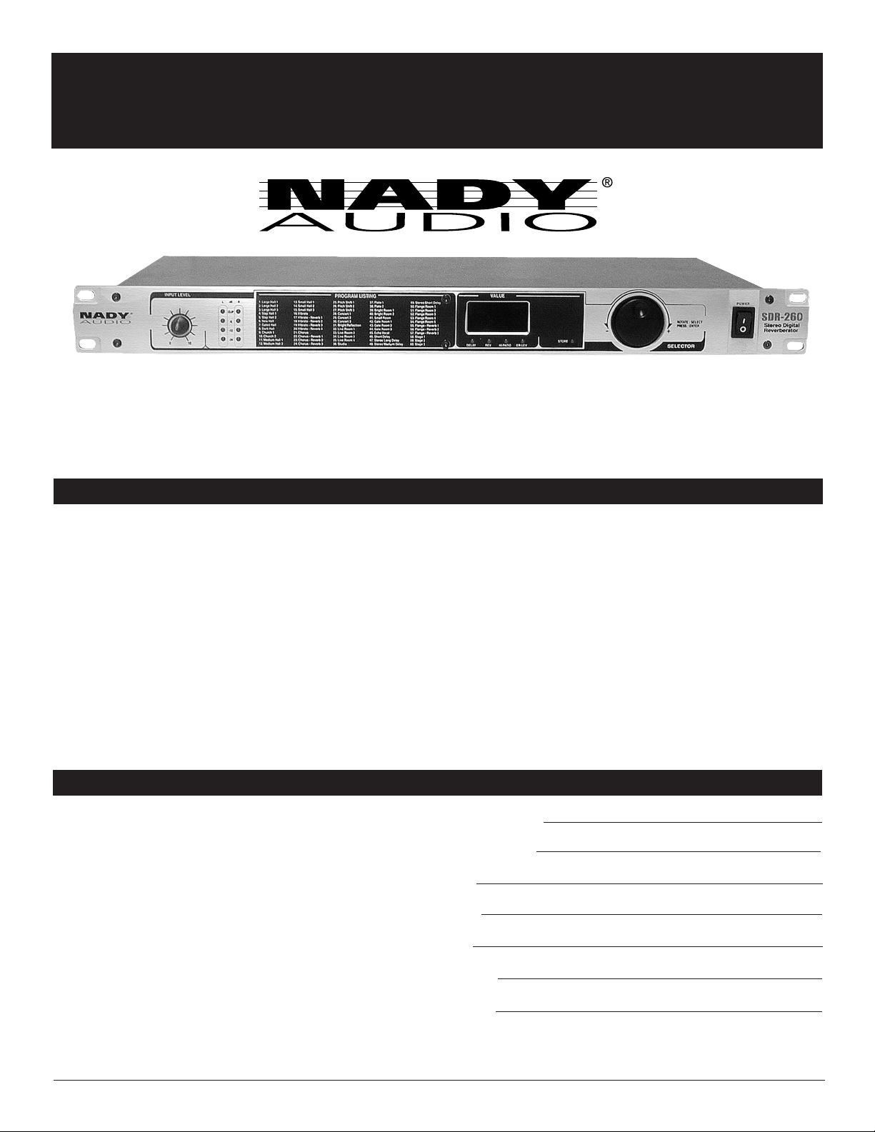
CONTROLS AND CONNECTIONS
FRONT PANEL
(1) (2) (5)
(3)
(6) (4)
(7)
1. INPUT GAIN CONTROL
Adjusts the input level of the audio signal to the unit.
2. INPUT LEVEL DISPLAY
This 4-segment bargraph displays the input level. The clip
LED's will light at 3dB below clipping.
3. VALUE INDICATOR
Whenever the SDR-260 is powered up, this displays the last
chosen effect number. In use, the display indicates different
alphanumeric information, depending on the mode selected.
• In NORMAL MODE it indicates which of the 255 effects
(1-255) has been selected.
• In EDIT MODE it indicates the editable value of the
parameter (0-127).
• In EQ MODE it indicates the editable value of the
parameter (0-127).
• In STORE MODE it indicates the address (1-20) being
saved.
• In LOAD MODE it indicates address (1-20) being
loaded.
4. PUSH & ROTARY CONTROL KNOB
This is the tool used to control the SDR-260
5. PARAMETER EDIT INDICATORS
Each indicator will light when the corresponding parameter is
being displayed - Delay/Reverb/HI Patio/Early Reflection
Level.
6. STORE INDICATORS
This indicator will light when in STORE MODE
7. POWER SWITCH
Use this switch to power unit ON or OFF. The integrated
LED will light when the unit is ON. Before turning on this unit,
verify connection to the proper voltage AC source, check all
connections and turn down the level controls of equipment
connected to the outputs.
RIGHT LEFT RIGHT LEFT
OUTPUTSMIDI IN
AC115V
AC230V
WARNING:
TO REDUCE THE RISK OF FIRE OR
ELECTRONIC SHOCK, DO NOT EXPOSE
THIS EQUIPMENT TO RAIN OR MOISTURE
POWER INPUT:
AC115V/230V
FUSE:
0.5A, F, 250V
-10dB +4dB
RIGHT LEFT RIGHT LEFT
INPUTS
-10dB +4dB
SERIAL
REAR PANEL
(8) (9) (14)
8. AC POWER CORD IEC CONNECTOR WITH
INTEGRATED FUSE HOLDER
This standard IEC power cord receptacle is used to connect
the AC power to your unit. It features a built-in fuse holder for
a 5X20mm, 0.5A/250V slow-blow fuse. If the fuse
continuously blows, shut of the unit and have it serviced by
qualified service personnel.
9. AC VOLTAGE SELECT SWITCH
Before plugging in the power cord, check to see that the unit
is set for the proper voltage for your area: ~115V (60Hz) or
~230V (50Hz).
(Note: use at the improper voltage can damage your unit and
void the warranty.)
(10)
(11)
(12)
10. MIDI INPUT PORT
Receives MIDI Program Messages on MIDI Channel 1.
11. INPUTS
Unbalanced 1/4" (6.3mm) and balanced XLR inputs for both
left and right channels.
12. INPUTS LEVEL SWITCH
Switches between –10dB and +4dB input level attenuation.
13. OUTPUT LEVEL SWITCH
Switches between –10dB and +4dB output level attenuation.
14. OUTPUTS
Unbalanced 1/4" (6.3mm) and balanced XLR outputs for both
left and right channels.
(13)
Page 6

OPERATION
6
GETTING STARTED
Set the INPUT VOLTAGE SELECT SWITCH (8) for either
~115V(60Hz) or ~230V(50Hz) AC power. Attach the power
cord and plug it in.
Connect the Input and Output signals from the SDR-260 to
your audio system with the appropriate XLR balanced or 1/4”
unbalanced INPUT and OUTPUT JACKS (11, 13, 14, 16),
depending on the type of cable and connectors you’re using.
For Mono input use the Left channel input connector. XLR
output is disconnected when output 1/4” jack is inserted.
Turn the POWER SWITCH (7) On. You will see the preset
Program number [P 1] on the VALUE INDICATOR (3).
ADJUSTING LEVELS
Adjust the INPUT GAIN CONTROL (1) for the highest setting
without the red top L/R LED indicators of the INPUT LEVEL
DISPLAY (2) staying on continuously. Occasional flickering of
these red LED indicators is normal.
The INPUT LEVEL SWITCH (15) and OUTPUT LEVEL
SWITCH (12) are provided to adjust the levels for the
optimum performance. Adjust the level controls to minimum
noise and distortion while operating with the components of
your sound system.
MODE SELECTION
Pressing the ROTARY CONTROL KNOB (6) quickly will cycle
the modes from “P” Preset programs [P1-P60], to “U” User
programs [U1-U60] where custom programs are stored, to
finally PAS where the effects are bypassed.
BYPASS EFFECTS
The effects are disabled in the “PAS” mode.
SELECTING EFFECTS
In the Preset programs mode there are 60 preset effects,
select one by rotating the ROTARY CONTROL KNOB (6)
through the sixty choices. Stop at the desired choice and the
audio will mute briefly while the program is loaded. See
Preset PROGRAM LISTING of effects on the front panel.
In the User mode there are 60 locations for custom effects,
select one by entering the User mode and rotating the knob
through the sixty choices.
CUSTOM EFFECTS
Custom effects are modified preset programs. There are 60
locations for storing custom effects. Enter the Edit mode by
holding the ROTARY CONTROL KNOB (6) in for 3 seconds.
The display will show the value of the program parameter.
Rotating the knob will raise or lower the program subcategory parameter value. Pressing the knob quickly will cycle
the sub-categories DELAY (1-250mS), REV (1-99%), HIPATIO (0.1-1.0), ER-LVL (1-99). After adjusting the parameter
values for the desired sound the custom effect can be stored.
Holding the knob in for 3 seconds will enter STORE mode.
The Save LED and the “U” will flash; rotate the knob to select
the storage location [U1-U60]. To complete the STORE
process, Hold the knob in for 3 seconds, the STORE LED will
blink twice indicating the changes have been stored. To
cancel the STORE process press and release the knob
quickly.
REMOTE CONTROL USING MIDI
Connect the SDR-260 to the MIDI controller via the rear panel
MIDI INPUT (10) connector.
Receives MIDI Program Messages on MIDI Channel 1.
Prgm Mess. 1-60 for Preset Programs 1-60
Prgm Mess. 61-120 for User Programs 1-60
Prgm Mess. 121 for Bypass Mode
Page 7

PRESET PROGRAM LIST
7
# NAME
Hall Effects
1 Large Hall 1
2 Large Hall 2
3 Large Hall 3
4 Slap Hall 1
5 Slap Hall 2
6 New Hall
7 Gated Hall
8 Dark Hall
9 Church 1
10 Church 2
11 Medium Hall 1
12 Medium Hall 2
13 Small Hall 1
14 Small Hall 2
15 Small Hall 3
Vibrato Effects
16 Vibrato
17 Vibrato ➞ Reverb 1
18 Vibrato ➞ Reverb 2
19 Vibrato ➞ Reverb 3
20 Vibrato ➞ Reverb 4
Chorus Effects
21 Chorus
22 Chorus ➞ Reverb 1
23 Chorus ➞ Reverb 2
24 Chorus ➞ Reverb 3
Pitch Shift Effects
25 Pitch Shift 1
26 Pitch Shift 2
27 Pitch Shift 3
Concert Effects
28 Concert 1
29 Concert 2
30 Concert 3
# NAME
Room Effects
31 Bright Reflections
32 Live Room 1
33 Live Room 2
34 Live Room 3
35 Live Room 4
36 Studio
37 Plate 1
38 Plate 2
39 Bright Room 1
40 Bright Room 2
41 Small Room
42 Gated Room 1
43 Gated Room 2
44 Gated Room 3
Echo Effects
45 Echo Vocal
46 Short Delay
47 Stereo Long Delay
48 Stereo Medium Delay
49 Stereo Short Delay
Flanger Effects
50 Flange Room 1
51 Flange Room 2
52 Flange Room 3
53 Flange Room 4
54 Flange Room 5
55 Flange ➞ Reverb 1
56 Flange ➞ Reverb 2
57 Flange ➞ Reverb 3
Stage Effects
58 Stage 1
59 Stage 2
60 Stage 3
SPECIFICATIONS
The specifications above are correct at the time of printing of this manual. For improvement purposes, all specifications for this unit, including design
and appearance, are subject to change without prior notice.
ANALOG AUDIO INPUTS (Needs to be corrected and updated)
Connectors ......................XLR and 1/4” jack
Type..................................RF filtered, servo balanced input
Impedance ......................60K Ω balanced, 30K Ω unbalanced
ANALOG AUDIO OUTPUTS
Connectors ......................XLR and 1/4” jack
Type..................................Electronically servo-balanced output stage
Impedance........................60 Ω balanced, 30 Ω unbalanced
SYSTEM SPECIFICATIONS
Bandwidth ........................18 kHz to 20 kHz, ±3 dB
Noise ..............................> 94 dBu, unweighted, 20 Hz to 20 kHz
MIDI INTERFACE
Type.................................. 5-Pin-DIN-Socket, Input
DIGITAL PROCESSING
A/D & D/A Converters ......24-bit Sigma-Delta, 64/128-times oversampling
Sampling Rate ..................44.1 kHz
DISPLAYS
Type..................................3-digit alphanumeric LED display and individual
status LED indicators
POWER SUPPLY
Power requirement ..........Selectable, ~100-120VAC,
~200-240VAC, 50-60 Hz
Power Consumption ........Max. 10 Watts
Fuse..................................100-120 VAC: 630 mA(slow-blow)
200-240 VAC: 315 mA(slow-blow)
5X20mm glass type
Power cord connector ......Standard IEC receptacle
with built-in fuse holder
PHYSICAL
Dimensions ......................1.75” x 19” x 7.5” (44.5 x 483 x 191mm)
Weight ..............................7.5 lbs (3.40Kg)
Page 8

NADY SYSTEMS, INC. • 6701 SHELLMOUND STREET, EMERYVILLE, CA 94608
Tel: 510.652.2411 • Fax: 510.652.5075 • www.nady.com
SERVICE FOR YOUR NADY AUDIO PRODUCT
(U.S.) Should your NADY AUDIO product require service, please contact the Nady Service Department via
telephone at (510) 652-2411, or e-mail at service@nady.com.
(International) For service, please contact the NADY AUDIO distributor in your country through the dealer from
whom you purchased this product.
DO NOT ATTEMPTTO SERVICE THIS UNIT
YOURSELF AS IT CAN BE DANGEROUS
AND WILL ALSO VOID THE WARRANTY.
 Loading...