

Page 1
OWNER’S MANUAL
SDP-20
EFFECTS PROCESSOR
STEREO DIGITAL MULTI-EFFECTS PROCESSOR
Page 2
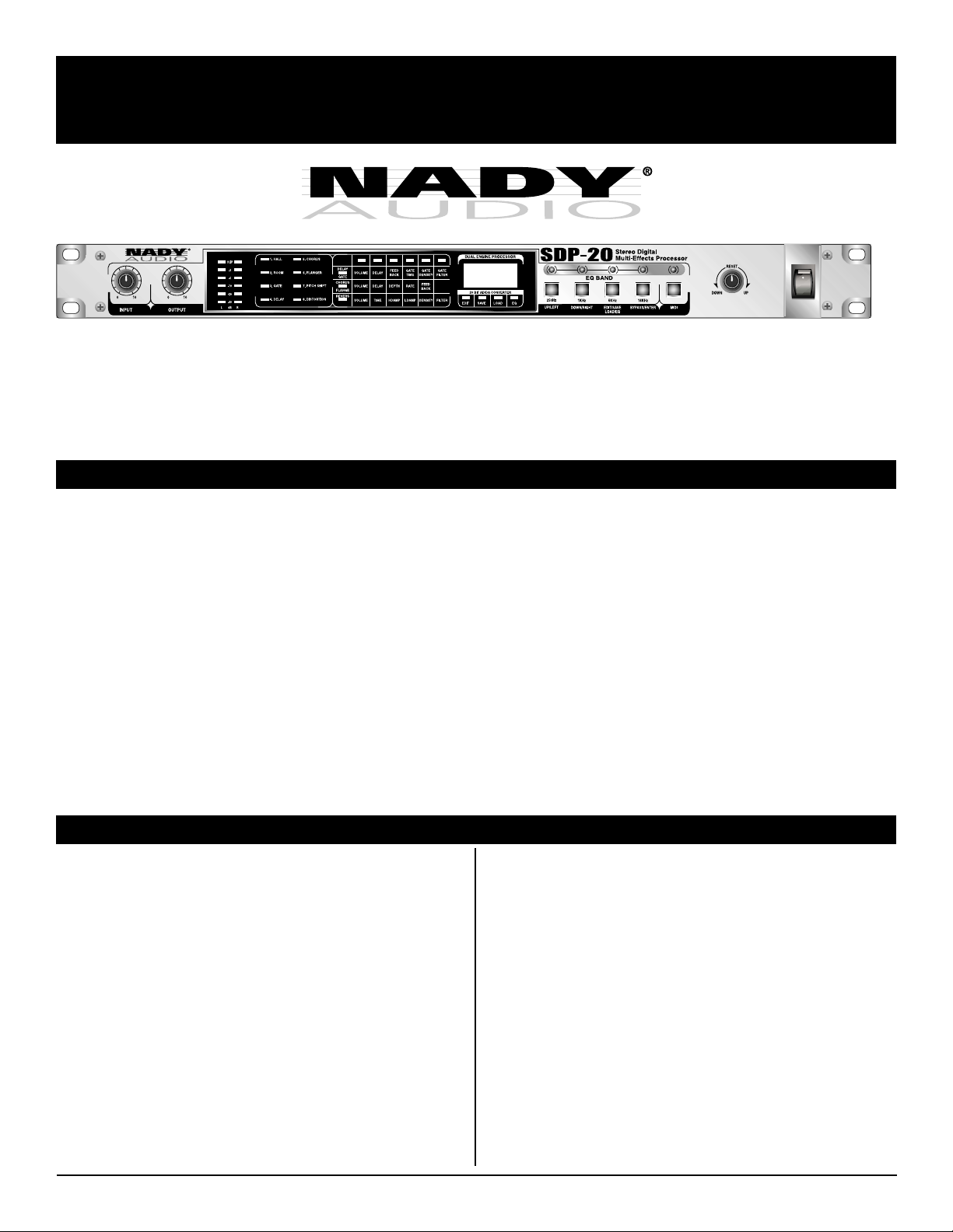
SDP-20
Stereo/Dual Channel 256 preset Programmable Digital Effects Processor
Congratulations on your choice of Digital Effects Processor — you have purchased one of the finest Digital Effects Processors on the
market today. This unit was developed using the expertise of professional sound engineers and working musicians. You will find that
your new NADY AUDIO SDP-20 has superior performance and greater flexibility than any other Digital Effects Processors in its price
range. Please read this manual carefully to get the most out of your new unit.
Thanks for selecting NADY AUDIO as your choice in Digital Effects Processor.
FEATURES
An indispensable ally in numerous studio and stage applications, the versatile SDP-20 enables boundless creativity with its richly
textured, complexly detailed algorithms.
• Powerful dual engine digital sound processor (DSP) offers a full •
Powerful dual engine digital sound processor (DSP) offers a full
complement of 256 of the latest and most useful breath-taking
effects presets including room and hall reverbs, gates, delays/
echoes, chorus/flanging/Leslie, pitch shifting, and overdrive/
distortion.
• Intuitive and easy to operate-all parameters can be selected and/
or edited (up to 6 editable parameters for each effect) via the jog
wheel knob or external MIDI remote control (via MIDI nrpn
messages) with 20 user program locations for personal edits
storage
• 20 bit A/D and D/A converters with 64/128 times oversampling
for ultra-high headroom and resolution
• Internal 20-bit processing with 46.875 kHz sampling rate for
unsurpassed audio
• 4 band digital equalizer, programmable by push buttons and the
jog wheel knob.
• Servo-balanced inputs and outputs with XLR and 1/4" TRS
connectors.
• Full remote MIDI control of all functions and parameters
• 6 segment ultra-precise stereo input level LED display
• 3 Digit program and parameter LED display
• External effects control via rear panel 1/4" jack for changing
preset program counter incrementally via optional external foot
switch
• Selectable Bypass with rear panel 1/4" jack for optional external
Bypass Foot switch
• Rugged construction for maximum long term reliability
• Shielded internal dual regulated power supply with
~115V(60Hz)/~230V(50Hz) select switch and fused IEC power
cord connector
TABLE OF CONTENTS
FEATURES ................................................................................. 2
WARNING................................................................................... 3
INSTALLATION .......................................................................... 4
CONTROLS AND CONNECTORS............................................. 5
Front Panel........................................................................... 5
Back Panel........................................................................... 6
OPERATION............................................................................... 6
Getting Started .................................................................... 6
Selecting an Effect............................................................... 6
Bypass ................................................................................. 7
Adjusting Levels................................................................... 7
Audio Equalizer.................................................................... 7
Custom Effects..................................................................... 7
Remote Control.................................................................... 7
PRESET PROGRAM LIST ......................................................... 8
SPECIFICATIONS .................................................................... 11
LEGAL INFORMATION............................................................ 11
Date of Purchase ____________________________________
Dealer’s Name ______________________________________
City _______________________________________________
State _____________________ Zip _____________________
Model # ____________________________________________
Serial # ___________________
2
Page 3

WARNING
An equilateral triangle enclosing a lightening flash/arrowhead symbol is
intended to alert the user to the presence of uninsulated “dangerous
voltage” within the product’s enclosure which may be of sufficient
ATTENTION: RISQUE DE CHOC ELECTRIQUE NE PAS OUVRIR
magnitude to constitute a risk of electric shock.
An equilateral triangle enclosing an exclamation point is intended to alert
the user to the presence of important operating and service instructions in
the literature enclosed with this unit.
IMPORTANT SAFETY INSTRUCTIONS
When using this electronic device, basic precautions should always be taken, including the following:
1. Read all instructions before using the product.
2. Do not use this product near water (e.g., near a bathtub, washbowl, kitchen sink, in a wet basement, or near a swimming
pool, etc.).
3. This product should be used only with a cart or stand that will keep it level and stable and prevent wobbling.
4. This product, in combination with headphones or speakers, may be capable of producing sound levels that could cause
permanent hearing loss. Do not operate for a long period of time at a high volume level or at a level that is uncomfortable.
If you experience any hearing loss or ringing in the ears, you should consult an audiologist.
5. The product should be positioned so that proper ventilation is maintained.
6. The product should be located away from heat sources such as radiators, heat vents, or other devices
(including amplifiers) that produce heat.
7. The product should be connected to a power supply only of the type described in the operating instructions or as marked on the
product. Replace the fuse only with one of the specified type, size, and correct rating.
8. The power supply cord should: (1) be undamaged, (2) never share an outlet or extension cord with other devices so that the
outlet’s or extension cord’s power rating is exceeded, and (3) never be left plugged into the outlet when not being used for
a long period of time.
9. Care should be taken so that objects do not fall into, and liquids are not spilled through, the enclosure’s openings.
10. The product should be serviced by qualified service personnel if:
A. The power supply cord or the plug has been damaged.
B. Objects have fallen into, or liquid has been spilled onto the product.
C. The product has been exposed to rain.
D. The product does not appear to operate normally or exhibits a marked change in performance.
E. The product has been dropped, or the enclosure damaged.
11. Do not attempt to service the product beyond what is described in the user maintenance instructions. All other servicing should
be referred to qualified service personnel.
3
Page 4

INSTALLATION
To ensure years of enjoyment from your NADY AUDIO SDP-20, please read and understand this manual thoroughly before
using the unit.
INSPECTION
Your SDP-20 was carefully packed at the factory in packaging designed to protect the units in shipment. Before installing and using
your unit, carefully examine the packaging and all contents for any signs of physical damage that may have occurred in transit.
(Note: Nady Systems is not responsible for shipping damage. If the unit is damaged, do not return to us, but notify your dealer and the
shipping company immediately to make a claim. Such claims must be made by the consignee in a timely manner.)
CONTENTS:
• Instruction manual
• SDP-20 (verify that the unit’s serial number is same as shown on shipping carton)
• AC Power cord
• Warranty Card
RACK MOUNTING
The SDP-20 fits into one standard 19" rack unit of space (1 3/4"). Parts of the unit can become very warm during use. This is normal
during operation. Care should be taken to ensure that there is enough space around the unit for cooling (at least 12” or 30cm). Do not
place the SDP-20 on high temperature devices such as power amplifiers, etc., or the unit may overheat in operation. Also, do not
place the unit on speakers as this may cause them to move and/or fall due to speaker vibrations.
Although the unit’s chassis is shielded against radio frequency (RF) and electromagnetic interference (EMI), extremely high fields of RF
and EMI should be avoided.
POWER CONNECTION
The SDP-20 has an internal power supply and is designed to operate from an external AC source. Power requirements for electrical
equipment differ from area to area. Be sure to confirm that the voltage selected by the voltage selector switch on the back panel is
proper for your area (120VAC/60 Hz or 230VAC/50Hz) per the information below:
Europe (except UK): 230V, 50Hz
UK and Australia: 240V, 50Hz
USA and Canada: 120V, 60 Hz
For other areas, please check with local authorities.
When ready to operate, plug the AC cord into the power source. Make sure that the unit is turned off before connecting to the AC
power source to avoid possible loud transients which can damage your speakers or your ears, especially when monitoring with
headphones.
4
Page 5

CONTROLS AND CONNECTORS
FRONT PANEL
(1) (2)
1. INPUT GAIN CONTROL
Adjusts the input level of the audio signal to the unit.
2. OUTPUT LEVEL CONTROL
Adjusts the output signal from the unit to match the differing
requirements of connected equipment.
3. INPUT LEVEL DISPLAY
6-segment stereo LED display indicates the level input to the unit.
4. EFFECT TYPE DISPLA Y
8 LED display indicates which of 8 possible effect types has been
selected.
5. PARAMETER DISPLAY
Each effect has up to 6 editable parameters. The effect type
selected is indicated by the 3 LEDs in the column on the left side
of this display. The LED above the 6 columns to the right indicates
the editable parameter selected for the chosen effect. This display
is only valid in EDIT MODE. When a specific LED in this display
flashes, it indicates that the SDP-20 is in EDIT MODE and that the
parameter indicated can be changed. Select the next editable
parameter by pressing the UP/LEFT (7) key or choose the
previous editable parameter by pressing the DOWN/RIGHT (8)
key . The VALUE ADJUSTMENT CONTROL (12) is used to
change parameters: UP to increase the parameter and DOWN to
decrease it. The PROGRAM/VARIA TION DISPLAY (6) indicates
the parameter changes.
6a. PROGRAM/V ARIA TION DISPLAY
Whenever the SDP-20 is powered up, this displays the last
chosen effect number . In use, the display indicates dif ferent
alphanumeric information, depending on the mode selected.
• In NORMAL MODE it indicates which of the 255 effects
(1-255) has been selected.
• In EDIT MODE it indicates the editable value of the
parameter (0-127).
• In EQ MODE it indicates the editable value of the
parameter (0-127).
• In SAVE MODE it indicates the address (1-20) being
saved.
• In LOAD MODE it indicates address (1-20) being loaded.
6b. MODE DISPLA Y
This indicates which of the MODES above is selected. Use the
EDIT/SAVE/LOAD/EQ SELECTOR & 5KHZ EQ SELECT KEY
(9) To select the MODE desired. When all the LEDs in this display
are off the unit is in NORMAL MODE. Note that if the unit is left
non operational for a while, it will enter NORMAL MODE by itself.
(3)
(4)
(5) (7) (8) (9) (10) (11)
(6a)
(12)
(6b)
7. UP/LEFT & 250HZ EQ SELECT KEY
Use this key in NORMAL/EDIT/EQ MODE to select effect type,
edit parameters, or edit EQ parameters. When the corresponding
LED lights, the EQ parameters in this frequency range can be
changed and the PROGRAM/V ARIATION DISPLAY (6a) will
indicate present value (64 = 0dB, 127 = +12dB and 0 = -12dB)
8. DOWN/RIGHT & 1KHZ EQ SELECT KEY
Use this key in NORMAL/EDIT/EQ MODE to select effect type,
edit parameters, or edit EQ parameters. When the corresponding
LED lights, the EQ parameters in this frequency range can be
changed and the PROGRAM/V ARIATION DISPLAY (6a) will
indicate present value (64 = 0dB, 127 = +12dB and 0 = -12dB)
9. EDIT/SA VE/LOAD/EQ SELECT OR & 5KHZ EQ SELECT KEY
Use this key to change MODES. The MODE selected is indicated
on the MODE DISPLAY (6b). When the corresponding LED
lights, the EQ parameters in this frequency range can be changed
and the PROGRAM/V ARIATION DISPLAY (6a) will indicate
present value (64 = 0dB, 127 = +12dB and 0 = -12dB)
10. BYPASS/ENTER & 16KHZ EQ SELECT KEY
Use this key to turn effect on or off. With BYPASS selected (effect
off), both the EFFECT TYPE DISPLAY (4) and the PARAMETER
DISPLAY (5) will be off and the PROGRAM/VARIATION DISPLAY (6a) will indicate “OFF”. In SAVE/LOAD MODE, this
functions as the confirm key (ENTER).
EQ is not off and can still be edited.)
LED lights, the EQ parameters in this frequency range can be
changed and the PROGRAM/V ARIATION DISPLAY (6a) will
indicate present value (64 = 0dB, 127 = +12dB and 0 = -12dB)
11. MIDI SELECT KEY
Use this key to select MIDI control mode. The corresponding LED
indicator will light and the PROGRAM/VARIATION DISPLAY (6a)
will display “256” to indicate that the unit is in MIDI control mode.
12. VALUE ADJUSTMENT CONTROL
Use this control to select effects, edit effect parameters and edit
EQ parameters.
13. POWER SWITCH
Use this switch to power unit ON or OFF. The integrated LED will
light when the unit is ON. Before turning on this unit, verify
connection to the proper voltage AC source, check all connections
and turn down the level controls of equipment connected to the
outputs.
(Note: In OFF state, the
When the corresponding
(13)
5
Page 6

REAR PANEL
CONTROLS AND CONNECTORS
(14) (15) (16) (18a)(17) (19) (20) (21) (22) (23) (24) (25) (26) (27)
14. AC POWER CORD IEC CONNECTOR WITH INTEGRATED
FUSE HOLDER
This standard IEC power cord receptacle is used to connect the
AC power to your unit. It features a built-in fuse holder for a
5X20mm, 0.5A/250V slow-blow fuse. If the fuse continuously
blows, shut of the unit and have it serviced by qualified service
personnel.
15. AC VOL T AGE SELECT SWITCH
Before plugging in the power cord, check to see that the unit is set
for the proper voltage for your area: ~115V (60Hz) or ~230V
(50Hz).
(Note: use at the improper voltage can damage your unit and void
the warranty .)
16. PROGRAM INCREMENT FOOT SWITCH JACK
An optional external foot switch can also be connected to this jack
and used to step through the preset programs incrementally
one after the other. Contact your dealer or the NADY SER VICE
DEPARTMENT (see back page of this manual) for availability.
17. BYPASS FOOT SWITCH JACK
An optional external foot switch can be connected to this jack and
used to toggle the bypass mode ON/OFF successively . Contact
your dealer or the NADY SERVICE DEPARTMENT (see back
page of this manual) for availability .
(18b)
18a. MIDI INPUT PORT
18b. MIDI THRU PORT
19. MIDI OUTPUT PORT
20. RIGHT CHANNEL XLR BALANCED OUTPUT
21. RIGHT CHANNEL 1/4" UNBALANCED OUTPUT
22. RIGHT CHANNEL XLR BALANCED INPUT
23. RIGHT CHANNEL 1/4" UNBALANCED INPUT
24. LEFT CHANNEL XLR BALANCED OUTPUT
25. LEFT CHANNEL 1/4" UNBALANCED OUTPUT
26. LEFT CHANNEL XLR BALANCED INPUT
27. LEFT CHANNEL 1/4" UNBALANCED INPUT
OPERATION
The following instructions will describe how to operate the SDP-20. For further detail on specific functions and controls, also consult the
descriptions above (CONTROLS AND CONNECTIONS) as needed.
GETTING STARTED
Set the INPUT VOL TAGE SELECT SWITCH (15) for either
~115V(60Hz) or ~230V(50Hz) AC power. Attach the power cord
and plug it in.
Connect the Input and Output signals from the SDP-20 to your
audio system with the appropriate XLR balanced or 1/4"
unbalanced INPUT and OUTPUT JACKS (20 - 27), depending on
the type of cable and connectors you’re using.
Turn the POWER SWITCH (13) On. You will see the previously
selected preset Program number on the PROGRAM/VARIATION
DISPLAY (6).
SELECTING AN EFFECT
There are 255 preset effects. Use the EDIT/SAVE/LOAD/EQ
SELECTOR & 5KHZ EQ SELECT KEY to select the NORMAL
MODE. This MODE indicated on the MODE DISPLAY (6b) when
all the 4 LEDs are off. See
Chose between the main effect type desired using the UP/LEFT &
250HZ EQ SELECT KEY (7) to choose the previous effect type or
the DOWN/RIGHT & 1KHZ EQ SELECT KEY (8) to select the
next one. There are 8 main effect types that can be selected and
the one chosen will light up the corresponding LED on the
EFFECT TYPE DISPLAY (4). Select the desired choice of the 255
presets by rotating the V ALUE ADJUSTMENT CONTROL (12)
clockwise to select a higher number effect and counterclockwise
for a lower number effect. The EFFECT TYPE DISPLAY (4) and
the PROGRAM/VARIATION DISPLAY (6a) will indicate the effect
type and effect number selected. Note that all effects selected are
preset to their default values. Effect parameters can be edited.
(See CUSTOM EFFECTS, page 7)
6
PRESET PROGRAM LIST, page 8.
Page 7

OPERATION
An optional external foot switch can also be connected to the
PROGRAM INCREMENT FOOT SWITCH (16) jack and used to
step through the preset programs incrementally one after the
other. Contact your dealer or the NADY SERVICE DEPARTMENT
(see back page of this manual) for availability .
BYPASSING EFFECTS
Bypass the effects by pressing the front panel BYPASS SWITCH
(10). The PROGRAM/V ARIATION DISPLAY indicates “OFF” when
in bypass mode and all the LEDs in the EFFECT TYPE DISPLAY
(4) and P ARAMETER DISPLAY (5) will be off. When in BYPASS
(effects off) MODE, the EQ MODE is not off and EQ parameters
can be edited.
An optional external foot switch can be connected to the BYPASS
FOOT SWITCH (17) jack and used to toggle the bypass mode
ON/OFF successively . Contact your dealer or the NADY SERVICE
DEPARTMENT (see back page of this manual) for availability.
ADJUSTING LEVELS
Adjust the INPUT GAIN CONTROL (1) for the highest setting
without the red top L/R LED indicators of the INPUT LEVEL
DISPLA Y (3) staying on continuously. Occasional flickering of
these red LED indicators is normal.
VALUE ADJUSTMENT CONTROL (12) to modify the
variable to the desired sound. The PROGRAM/VARIATION
DISPLAY (6a) will indicate the corresponding value. Note
that the edited parameters can apply to the present state of
the effect selected or saved as custom values.
To save the modified values in a custom location:
Cycle the EDIT/SAVE/LOAD/EQ (9) key to the “SAVE”
mode as indicated by the MODE DISPLAY (6b). Use the
VALUE ADJUSTMENT CONTROL (12) to select the
custom storage location 1 thru 20 as indicated by the
flashing PROGRAM/VARIATION DISPLAY (6a). Press the
ENTER (10) key to store the custom effect and return to
the NORMAL MODE. (
Note that if the unit is left non
operational for a while, it will enter NORMAL MODE by
itself).
To recall a custom effect:
Cycle the EDIT/SAVE/LOAD/EQ (9) key to the “LOAD”
mode as indicated by the MODE DISPLAY (6b). Use the
VALUE ADJUSTMENT CONTROL (12) to select the
custom storage location 1 thru 20 indicated by the flashing
PROGRAM/VARIATION DISPLAY (6a). Press the ENTER
(10) key and return to the NORMAL MODE.
(Note that if
the unit is left non operational for a while, it will enter
NORMAL MODE by itself).
Adjust the OUTPUT LEVEL CONTROL (2) for the optimum level
and minimum noise for driving the connected components of your
sound system.
AUDIO EQUALIZER
The equalizer settings are independent of the preset program or
custom program settings. The value of each frequency band is
stored in non-volatile memory and is recovered when the unit is
turned on. Values for each band can be set between 1 and 128
with the center at 64. For each effect selected, the EQ parameter
can be edited and saved.
Select EQ mode using the EDIT/SA VE/LOAD/EQ (9) key. As you
press the KEY (9) the corresponding LED will light and you will
see the MODE DISPLAY (6b) change between functions. Select
“EQ”. The UP (7) and DOWN (8) buttons will select the specific
EQ Band desired (250Hz, 1KHz, 5KHz, 16KHz). Adjust the level
with the VALUE ADJUSTMENT CONTROL (12) (64 = 0dB, 127 =
+12dB and 0 = -12dB). Press BYPASS/ENTER KEY (10) to
confirm changes and return to NORMAL MODE.
(Note that if the
unit is left non operational for a while, it will enter NORMAL MODE
by itself).
CUSTOM EFFECTS
Custom effects are modified preset effects. There are 20 locations
for storing custom effects. The Save and Load functions of the
EDIT/SA VE/LOAD/EQ (9) key provide write and read of the
custom non-volatile memory location.
Auto-save function:
If the unit is turned off after changing parameters or values
during operation (including selected effects, effect
parameters, EQ values, etc.), its auto save function will
automatically retain these changes for the next time the
unit is powered on, even if the user does not save them.
REMOTE CONTROL USING MIDI
1) Use the DRFX.exe application on a PC. The application
controls the sound card “Game Port”, 15 pin D-sub connector.
The application can be downloaded from the Nady.com web
site.
2) Connect the PC to the SDP-20 MIDI IN connector via
interconnect cable. The MIDI interconnect cable is available
from Nady .
3) Push the front panel switch MIDI (11) to allow remote control.
4) Launch the application on the PC. Adjust the software slider
controls for desired sound.
To capture and edit the preset value:
Choose a preset effect similar to the desired effect. Cycle
the EDIT/SAVE/LOAD/EQ (9) key to the “EDIT” mode. The
UP (7) and DOWN (8) buttons will select the variable field:
Volume, Delay, Feed Back, Time, Density , or Filter. Use the
7
Page 8

PRESET PROGRAM LIST
HALL PRESETS REVERB
HALL: large hall
# Name
1 HALL1 1.0s
2 HALL1 1.2s
3 HALL1 1.5s
4 HALL1 1.8s
5 HALL1 2.0s
6 HALL1 2.2s
7 HALL1 2.5s
8 HALL1 2.8s
9 HALL1 3.0s
10 HALL1 3.5s
11 HALL1 4.0s
12 HALL1 4.5s
13 HALL1 5.0s
14 HALL1 6.0s
15 HALL1 8.0s
16 HALL1 10.0s
HALL HIDAMP
large half w/high frequency filter on decay
17 HALL1 HIDAMP 1.0s
18 HALL1 HIDAMP 1.2s
19 HALL1 HIDAMP 1.5s
20 HALL1 HIDAMP 1.8s
21 HALL1 HIDAMP 2.0s
22 HALL1 HIDAMP 2.2s
23 HALL1 HIDAMP 2.5s
24 HALL1 HIDAMP 2.8s
25 HALL1 HIDAMP 3.0s
26 HALL1 HIDAMP 3.5s
27 HALL1 HIDAMP 4.0s
28 HALL1 HIDAMP 4.5s
29 HALL1 HIDAMP 5.0s
30 HALL1 HIDAMP 6.0s
31 HALL1 HIDAMP 8.0s
32 HALL1 HIDAMP 10.0s
33 ROOM 0.5s
34 ROOM 0.8s
35 ROOM 1.0s
36 ROOM 1.2s
HALL HIDAMP
large half w/high frequency filter on decay
37 ROOM 1.5s
38 ROOM 1.8s
39 ROOM 2.0s
40 ROOM 2.2s
41 ROOM 2.5s
42 ROOM 2.8s
43 ROOM 3.0s
44 ROOM 3.2s
45 ROOM 3.5s
46 ROOM 3.8s
47 ROOM 4.0s
48 ROOM 4.2s
49 ROOM HIDAMP 0.5s
50 ROOM HIDAMP 0.8s
51 ROOM HIDAMP 1.0s
52 ROOM HIDAMP 1.2s
53 ROOM HIDAMP 1.5s
54 ROOM HIDAMP 1.8s
55 ROOM HIDAMP 2.0s
56 ROOM HIDAMP 2.2s
57 ROOM HIDAMP 2.5s
HALL HIDAMP
large half w/high frequency filter on decay
58 ROOM HIDAMP 2.8s
59 ROOM HIDAMP 3.0s
60 ROOM HIDAMP 3.2s
61 ROOM HIDAMP 3.5s
62 ROOM HIDAMP 3.8s
63 ROOM HIDAMP 4.0s
64 ROOM HIDAMP 4.2s
HALL PRESETS REVERB
HALL: medium size room
# Name
65 HALL2 1.0s
66 HALL2 1.2s
67 HALL2 1.5s
68 HALL2 1.8s
69 HALL2 2.0s
70 HALL2 2.2s
71 HALL2 2.5s
HALL PRESETS REVERB
72 HALL2 2.8s
73 HALL2 3.0s
74 HALL2 3.5s
75 HALL2 4.0s
76 HALL2 4.5s
77 HALL2 5.0s
78 HALL2 6.0s
79 HALL2 8.0s
80 HALL2 10.0s
ROOM HIDAMP
medium size room w/high frequency filter on decay
81 HALL2 HIDAMP 1.0s
82 HALL2 HIDAMP 1.2s
83 HALL2 HIDAMP 1.5s
84 HALL2 HIDAMP 1.8s
85 HALL2 HIDAMP 2.0s
86 HALL2 HIDAMP 2.2s
87 HALL2 HIDAMP 2.5s
88 HALL2 HIDAMP 2.8s
89 HALL2 HIDAMP 3.0s
90 HALL2 HIDAMP 3.5s
91 HALL2 HIDAMP 4.0s
92 HALL2 HIDAMP 4.5s
93 HALL2 HIDAMP 5.0s
94 HALL2 HIDAMP 6.0s
95 HALL2 HIDAMP 8.0s
96 HALL2 HIDAMP 10.0s
8
Page 9
PRESET PROGRAM LIST
GATE PRESETS
# Name
97 Low density forward gate 100 ms
98 Low density forward gate 150 ms
99 Medium density forward gate 200 ms
100 Medium density forward gate 250 ms
101 High density forward gate 300 ms
102 High density forward gate 350 ms
103 High density forward gate 400 ms
104 High density forward gate 450 ms
105 High density forward gate 500 ms
106 Low density reverse gate 100 ms
107 Low density reverse gate 150 ms
108 Medium density reverse gate 200 ms
109 Medium density reverse gate 250 ms
110 High density reverse gate 300 ms
111 High density reverse gate 350 ms
112 High density reverse gate 400 ms
113 High density reverse gate 450 ms
114 High density reverse gate 500 ms
115 Medium density left to right gate 500ms
116 High density left to right gate 500ms
DELAY/ECHO PRESETS
# Name
117 3/4 time echo
118 3/4 time panned echo
119 4/4 time echo 1
120 4/4 time panned echo 1
121 4/4 time echo 2
122 4/4 time panned echo 2
123 Triplet
124 Panned triplet
125 Single delay 20ms
126 Single delay 25ms
127 Single delay 30ms
128 Single delay 35ms
129 Single delay 40ms
130 Single delay 45ms
131 Single delay 50ms
132 Single delay 55ms
133 Single delay 60ms
134 Single delay 65ms
135 Single delay 70ms
136 Single delay 75ms
137 Single delay 80ms
138 Single delay 85ms
139 Single delay 90ms
140 Single delay 95ms
141 Single delay 100ms
142 Single delay 125ms
143 Single delay 150ms
144 Single delay 175ms
145 Single delay 200ms
146 Single delay 225ms
147 Single delay 250ms
148 Single delay 300ms
149 Single delay 350ms
150 Single delay 400ms
151 Single delay 450ms
152 Single delay 500ms
153 Single delay 550ms
154 Single delay 600ms
155 Single delay 650ms
156 Single delay 700ms
157 Regen 20% delay 100ms
DELAY/ECHO PRESETS
158 Regen 20% delay 125ms
159 Regen 20% delay 150ms
160 Regen 20% delay 175ms
161 Regen 20% delay 200ms
162 Regen 20% delay 225ms
163 Regen 20% delay 250ms
164 Regen 20% delay 300ms
165 Regen 20% delay 350ms
166 Regen 20% delay 400ms
167 Regen 20% delay 450ms
168 Regen 20% delay 500ms
169 Regen 20% delay 550ms
170 Regen 20% delay 600ms
171 Regen 20% delay 650ms
172 Regen 20% delay 700ms
173 Regen 40% delay 100ms
174 Regen 40% delay 125ms
175 Regen 40% delay 150ms
176 Regen 40% delay 175ms
177 Regen 40% delay 200ms
178 Regen 40% delay 225ms
179 Regen 40% delay 250ms
180 Regen 40% delay 300ms
181 Regen 40% delay 350ms
182 Regen 40% delay 400ms
183 Regen 40% delay 450ms
184 Regen 40% delay 500ms
185 Regen 40% delay 550ms
186 Regen 40% delay 600ms
187 Regen 40% delay 650ms
188 Regen 40% delay 700ms
189 Panning delay 100ms
190 Panning delay 100ms regen
191 Panning delay 200ms
192 Panning delay 200ms regen
193 Panning delay 300ms
194 Panning delay 300ms regen
195 Panning delay 350ms
196 Panning delay 350ms regen
197 Panning delay 400ms
198 Panning delay 400ms regen
199 Panning delay 450ms
200 Panning delay 450ms regen
9
Page 10
PRESET PROGRAM LIST
CHORUS PRESETS
# Name
201 Chorus light depth 1
202 Chorus light depth 2
203 Chorus medium depth 1
204 Chorus medium depth 2
205 Chorus high depth 1
206 Chorus high depth 2
207 Chorus fast 1
208 Chorus fast 2
209 Fast chorus with long delay
210 Quad chorus high feedback
211 Quad chorus resonant
212 Quad chorus medium depth
213 Quad chorus high depth
214 Deep stereo flanger
215 Leslie slow
216 Leslie fast
217 Chorus + Delay 1
218 Chorus + Delay 2
219 Chorus + Delay 3
220 Chorus + reverb 1
221 Chorus + reverb 2
222 Chorus + reverb 3
FLANGING PRESETS
# Name
223 Light depth flanger 1
224 Light depth flanger 2
225 Stereo light depth flanger
226 Medium depth flanger
227 Stereo medium depth flanger
228 Medium depth slow flanger
229 High depth flanger
230 Stereo high depth flanger
231 Flanging + Reverb 1
232 Flanging + Reverb 2
233 Flanging + Reverb 3
DISTORTION PRESETS
# Name
252 Low distortion
253 Medium distortion 1
254 Medium distortion 2
255 High distortion
NO SOUND
# Name
256 No sound
PITCH SHIFTER PRESETS
# Name
234 Up M3rd/Down 4th
235 Up m3rd/Down 4th
236 Up M3rd/Downaug4th
237 Up 4th detune
238 Down 4th detune
239 Up 5th detune
240 Down 5th detune
241 Down M6th detune
242 Down m6th detune
243 Down M2nd/Down 4th
244 Up oct/Down oct
245 Up oct detune
246 Down oct detune
247 Light detune
248 Deep detune
249 Doubler
250 Detune + regen delay
251 Down oct + regen delay
10
Page 11

SPECIFICATIONS
ANALOG AUDIO INPUTS
Connectors........................................................................ XLR and 1/4" jack
Type...................................................................................RF filtered, servo balanced input
Impedance ........................................................................ 60 k Ohms balanced, 30 k Ohms unbalanced
ANALOG AUDIO OUTPUTS
Connectors........................................................................ XLR and 1/4" jack
Type...................................................................................Electronically servo-balanced output stage
Impedance ........................................................................ 60 Ohms balanced, 30 Ohms unbalanced
SYSTEM SPECIFICA TIONS
Bandwidth ......................................................................... 20 Hz to 20 kHz, +0/-3 dB
Noise ................................................................................. > 94 dBu, unweighted, 20 Hz to 20 kHz
MIDI INTERFACE
T y p e................................................................................... 5-Pin-DIN-Socket, IN / OUT / THRU
DIGITAL PROCESSING
A/D & D/A Converters ....................................................... 20-bit Sigma-Delta, 64/128-times oversampling
Sampling Rate ..................................................................46.875 kHz
DISPLAYS
Type...................................................................................3-digit alphanumeric LED display and individual status LED indicators
POWER SUPPL Y
Power requirement............................................................Selectable, ~100-120VAC, ~200-240VAC, 50-60 Hz
Power Consumption.......................................................... Max. 10 Watts
Fuse .................................................................................. 100-120 V AC: 630 mA (slow-blow)
200-240 VAC: 315 mA (slow-blow)
100-240 VAC: 500 mA (slow-blow)
5X20mm glass type
Power cord connector .......................................................Standard IEC receptacle with built-in fuse holder
PHYSICAL
Dimensions ....................................................................... 1.75" x 19" x 7.5" (44.5 x 483 x 191mm)
Weight ............................................................................... 7.5 lbs (3.40Kg)
The specifications above are correct at the time of printing of this manual. For improvement purposes, all specifications for this unit,
including design and appearance, are subject to change without prior notice.
LEGAL INFORMATION
NOTICE
The information in this document is subject to change, as the Company may make changes to product in order to improve reliability,
design, or function, without prior written notice. No part of this manual may be reproduced or transmitted in any form or by any means
without the written permission of the company.
IN NO EVENT WILL THE COMP ANY BE LIABLE FOR SPECIAL INCIDENT AL OR CONSEQUENTIAL DAMAGES, WHETHER
ARISING DIRECTLY OR INDIRECTLY, SUCH AS LOSS OF PROFIT OR GOOD WILL, THAT MA Y BE SUFFERED IN CONNECTION
WITH THE PURCHASE OF THIS PRODUCT OR FROM THE BREACH OF ANY REPRESENTATION OR WARRANTY.
LICENSE
The Company grants the customer a non-exclusive, non-transferable license to use the software, if any, accompanying this product for
internal use on a single computer system. The end user may make a single copy of the software solely for backup purposes; otherwise,
no copies may be made of the software or any part thereof. No other license of any kind is granted to any part of the product or any of
the intellectual property therein.
11
Page 12

SERVICE FOR YOUR NADY AUDIO PRODUCT
(U.S.) Should your NADY AUDIO product require service, please contact the Nady Service Department via telephone
at (510) 652-2411, or e-mail at service@nady.com.
(International) For service, please contact the NADY AUDIO distributor in your country through the dealer from
whom you purchased this product.
DO NOT ATTEMPT TO SERVICE THIS UNIT
YOURSELF AS IT CAN BE DANGEROUS AND
WILL ALSO VOID THE WARRANTY.
NADY SYSTEMS, INC. • 6701 SHELLMOUND STREET, EMERYVILLE, CA 94608
Tel: 510.652.2411 • Fax: 510.652.5075 • www.nady.com
 Loading...