

Page 1
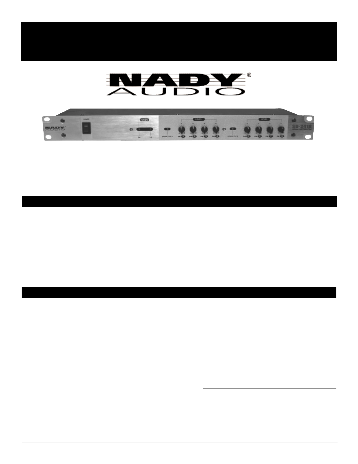
SD-2418
OWNER’S MANUAL
PRO RACK GEAR
Signal Distributor
Page 2
2
SD-2418
Signal Distributor
Congratulations on your choice of the SD-2418 signal distributor — you have purchased one of the finest
signal distributors on the market today. This unit was developed using the expertise of professional sound
engineers and working musicians. You will find that your new NADY AUDIO SD-2418 has superior
performance and greater flexibility than any other signal distributors in its price range. Please read this
manual carefully to get the most out of your new unit.
Thanks for selecting NADY AUDIO as your choice in audio products.
Date of Purchase
Dealer’s Name
City
State
Zip
Model #
Serial #
CONTENTS
FEATURES
• Splits balanced mono signal into 8 separate
balanced mono signals or stereo pair into four
separate stereo pairs
• Indispensable signal routing tool for live sound and
recording applications requiring signal splitting and
distribution with level matching to different
equipment
• Individual gain controls (up to +6dB gain) for all 8
outputs; 2-4,1-8 split mode select switch and
display; dual balanced inputs (Ch A,B) with Link
outputs for optimum signal routing flexibility in
hookup
• Wide dynamic range for optimum signal integrity
and transparency
FEATURES ..............................................................2
WARNING................................................................3
INSTALLATION........................................................4
LEGAL INFORMATION ..........................................4
CONTROL AND CONNECTORS............................5
SPECIFICATIONS....................................................6
Page 3

WARNING
3
IMPORTANT SAFETY INSTRUCTIONS
When using this electronic device, basic precautions should always be taken, including the following:
1. Read all instructions before using the product.
2. Do not use this product near water (e.g., near a bathtub, washbowl, kitchen sink, in a wet basement, or near a
swimming pool, etc.).
3. This product should be used only with a cart or stand that will keep it level and stable and prevent wobbling.
4. This product, in combination with headphones or speakers, may be capable of producing sound levels that
could cause permanent hearing loss. Do not operate for a long period of time at a high volume level or at a
level that is uncomfortable. If you experience any hearing loss or ringing in the ears, you should consult an
audiologist.
5. The product should be positioned so that proper ventilation is maintained.
6. The product should be located away from heat sources such as radiators, heat vents, or other devices
(including amplifiers) that produce heat.
7. The product should be connected to a power supply only of the type described in the operating instructions or
as marked on the product. Replace the fuse only with one of the specified type, size, and correct rating.
8. The power supply cord should: (1) be undamaged, (2) never share an outlet or extension cord with other
devices so that the outlet’s or extension cord’s power rating is exceeded, and (3) never be left plugged into
the outlet when not being used for a long period of time.
9. Care should be taken so that objects do not fall into, and liquids are not spilled through, the enclosure’s
openings.
10. The product should be serviced by qualified service personnel if:
A. The power supply cord or the plug has been damaged.
B. Objects have fallen into, or liquid has been spilled onto the product.
C. The product has been exposed to rain.
D. The product does not appear to operate normally or exhibits a marked change in performance.
E. The product has been dropped, or the enclosure damaged.
11. Do not attempt to service the product beyond what is described in the user maintenance instructions. All
other servicing should be referred to qualified service personnel.
ATTENTION: RISQUE DE CHOC ELECTRIQUE NE PAS OUVRIR
An equilateral triangle enclosing a lightening flash/arrowhead symbol is
intended to alert the user to the presence of uninsulated “dangerous
voltage” within the product’s enclosure which may be of sufficient
magnitude to constitute a risk of electric shock.
An equilateral triangle enclosing an exclamation point is intended to alert
the user to the presence of important operating and service instructions in
the literature enclosed with this unit.
Page 4

INSTALLATION
4
To ensure years of enjoyment from your NADY AUDIO SD-2418, please read and understand this manual thoroughly before
using the unit.
INSPECTION
Your NADY AUDIO SD-2418 was carefully packed at the factory in packaging designed to protect the units in shipment.
Before installing and using your unit, carefully examine the packaging and all contents for any signs of physical damage
that may have occurred in transit.
[Please note: Nady Systems is not responsible for shipping damage. If your unit is damaged, do not return to Nady, but
notify your dealer and the shipping company (if shipped to you) immediately to make a claim. Such claims must be made
by the consignee in a timely manner.]
CONTENTS
• Instruction manual
• SD-2418 (verify that the unit’s serial number is same as shown on shipping carton)
• AC Power cord
• Warranty Card
RACK MOUNTING
The SD-2418 fits into one standard 19” rack unit of space (1 3/4”). Parts of the unit can become very warm during use.
This is normal during operation. Care should be taken to ensure that there is enough space around the unit for cooling (at
least 12” or 30cm). Do not place the SD-2418 on high temperature devices such as power amplifiers, etc., or the unit may
overheat in operation. Also, do not place the unit on speakers as this may cause them to move and/or fall due to speaker
vibrations.
Although the unit’s chassis is shielded against radio frequency (RF) and electromagnetic interference (EMI), extremely
high fields of RF and EMI should be avoided.
POWER CONNECTION
The SDR-260 has an internal power supply and is designed to operate from an external AC source. Power requirements
for electrical equipment differ from area to area. Be sure to confirm that the voltage selected by the voltage selector switch
on the bottom panel is proper for your area (120VAC/60 Hz or 230VAC/50Hz) per the information below:
Europe (except UK): 230V, 50Hz
UK and Australia: 240V, 50Hz
USA and Canada: 120V, 60 Hz
For other areas, please check with local authorities.When ready to operate, plug the AC cord into the power source. Make
sure that the unit is turned off before connecting to the AC power source to avoid possible loud transients that can
damage your speakers or your ears, especially when monitoring with headphones.
NOTICE
The information in this document is subject to change, as the Company may make changes to product in order to improve
reliability, design, or function, without prior written notice. No part of this manual may be reproduced or transmitted in any form
or by any means without the written permission of the company.
IN NO EVENT WILL THE COMPANY BE LIABLE FOR SPECIAL INCIDENTAL OR CONSEQUENTIAL DAMAGES,
WHETHER ARISING DIRECTLY OR INDIRECTLY, SUCH AS LOSS OF PROFIT OR GOOD WILL, THAT MAY BE
SUFFERED IN CONNECTION WITH THE PURCHASE OF THIS PRODUCT OR FROM THE BREACH OF ANY
REPRESENTATION OR WARRANTY.
LICENSE
The Company grants the customer a non-exclusive, non-transferable license to use the software, if any, accompanying this
product for internal use on a single computer system. The end user may make a single copy of the software solely for backup
purposes; otherwise, no copies may be made of the software or any part thereof. No other license of any kind is granted to
any part of the product or any of the intellectual property therein.
LEGAL INFORMATION
Page 5

5
CONTROLS AND CONNECTIONS
(1) (2) (5)
1. POWER SWITCH
Use this switch to power unit ON or OFF. The integrated LED will
light when the unit is ON. Before turning on this unit, verify
connection to the proper voltage AC source, check all
connections and turn down the level controls of equipment
connected to the outputs.
2. MODE DISPLAY LED
The corresponding LED will light green to indicate whether the
SD-2418 is set to Single Mode 1-8 (stereo) or Dual Mode 2-4
(stereo). In Single Mode, the signal input into Ch Ais distributed
to outputs 1 through 8. In Dual Mode, the signal input into Ch A
is distributed to outputs 1 through 4 and a signal input into Ch B
is distributed to outputs 5 through 8.
3. CHANNEL A SIGNAL LED
This LED lights green when an audio signal is detected at the
input of Channel A. The LED will light red when the input signal
is too high and causes clipping. If the LED is blinking red, turn
down the volume level of the audio equipment source.
4. CHANNEL B SIGNAL LED
Same operation as Channel ALED
5. LEVEL CHANNELS (1 - 4)
Each control adjusts the Output volume of outputs 1-4 from
–∞to +6dB.
6. LEVEL CHANNELS (5 - 8)
Each control adjusts the Output volume of outputs 5-8 from
–
∞to +6dB.
(3) (4)
(6)
(1)(4)(6)
1. FUSE HOLDER & POWER CORD CONNECTOR
This fuse holder contains an AC primary fuse. When this fuse
blows, replace it with the same type fuse, size and power rating
(see SPECIFICATIONS). If it continuously blows, stop replacing
the fuse and refer servicing to qualified personnel. The cord
connector is used to connect the AC power source to your
power amplifier.
(CAUTION: After checking the AC supply voltage, be sure that
the correct fuse is in the fuse holder.)
CAUTION: DO NOT REMOVE THE AC PLUG CENTER
GROUNDING PIN.
2. SELECT SWITCH
This push button switch selects the mode of operation. When
the switch is out, Single Mode 1-8 (mono) is selected.
Depressing this button selects Dual Mode 2-4 (stereo).
3. INPUTS
Channel Aand Channel B XLR balanced line level inputs.
4. LINK OUTPUTS
Ch. Aand Ch. B XLR outputs linked in parallel with the
respective input.
5. OUTPUT CONNECTORS (1 - 4)
Balanced XLR outputs for Ch. Asignal.
6. OUTPUT CONNECTORS (5 - 8)
Balanced XLR outputs for Ch. Asignal, when in Single Mode,
and Ch. B signal when in Dual Mode.
Note: All output signals are in-phase with the input signal.
7. INPUT VOLTAGE SELECT SWITCH (BOTTOM PANEL)
Select 115V/60Hz or 230V/50Hz as appropriate for your area.
(CAUTION: Selecting the wrong voltage can damage your unit.
See also POWER CONNECTION, pg 4)
(2) (5) (3)
FRONT
REAR
(3) (4)
(7)
Bottom
Panel
Page 6

6
SPECIFICATIONS
The specifications above are correct at the time of printing of this manual. For improvement purposes, all specifications for this unit, including design
and appearance, are subject to change without prior notice.
Frequency Response ..................................................................20Hz - 20KHz +/-3dB
Total Harmonic Distortion (THD) + Noise ................................< 0.03 %
S/N Ratio......................................................................................> 98 dB
Maximum Gain ............................................................................+6dB per channel
Input Impedance ........................................................................20K Ω
Output Impedance ......................................................................300 Ω
Power ..........................................................................................115 VAC 60Hz / 230 VAC 50Hz
Rack Space..................................................................................1u
Dimensions ..................................................................................19’’ x 1.73’’ x 5.9’’ (483 X 44 X 150mm)
Weight ..........................................................................................5.3 lbs (2.4kg)
Page 7

Page 8

NADY SYSTEMS, INC. • 6701 SHELLMOUND STREET, EMERYVILLE, CA 94608
Tel: 510.652.2411 • Fax: 510.652.5075 • www.nady.com
SERVICE FOR YOUR NADY AUDIO PRODUCT
(U.S.) Should your NADY AUDIO product require service, please contact the Nady Service Department via
telephone at (510) 652-2411, or e-mail at service@nady.com.
(International) For service, please contact the NADY AUDIO distributor in your country through the dealer from
whom you purchased this product.
DO NOT ATTEMPT TO SERVICE THIS UNIT
YOURSELF AS IT CAN BE DANGEROUS
AND WILL ALSO VOID THE WARRANTY.
 Loading...