

Page 1
OWNER’S MANUAL
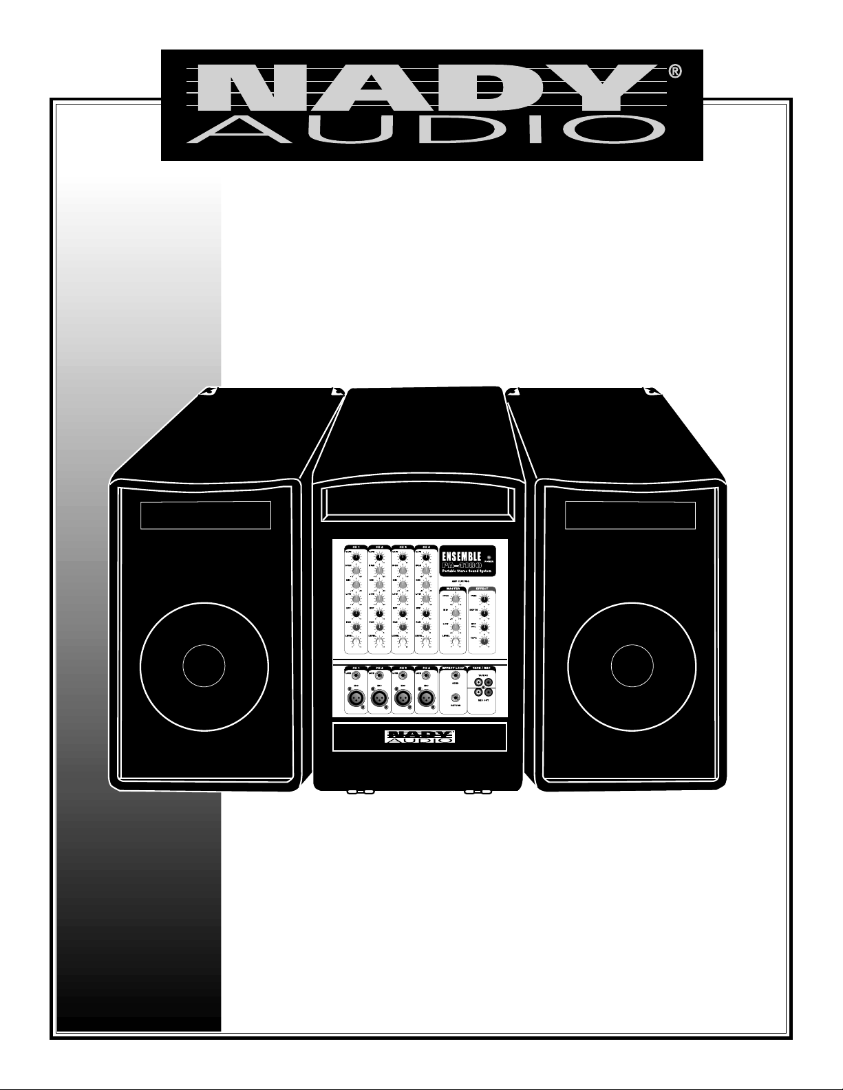
ENSEMBLE PA 4180
Portable Stereo Sound System
Page 2
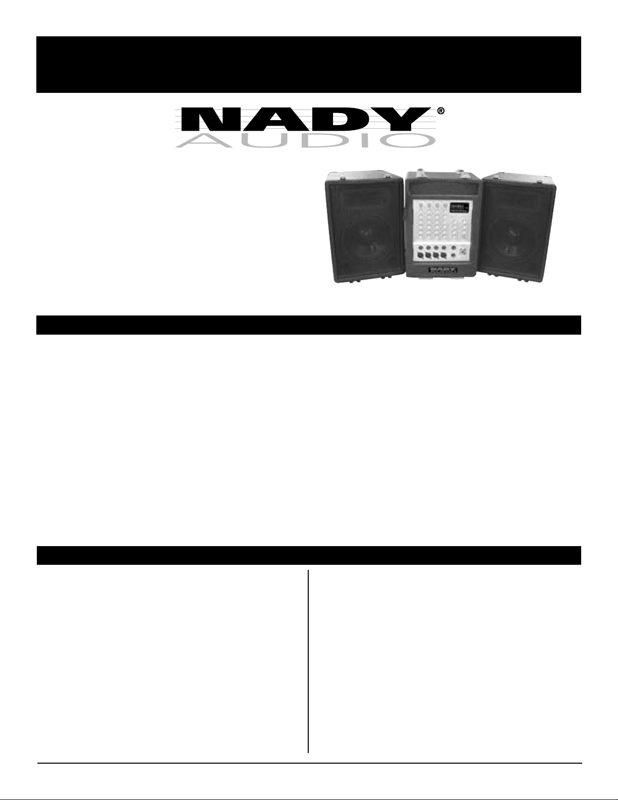
ENSEMBLE PA 4180
Portable Stereo Sound System
Congratulations on your choice of a portable sound system
— you have purchased one of the finest portable sound
systems on the market today. This unit was developed
using the expertise of professional sound engineers and
working musicians. You will find that your new NADY
AUDIO portable sound systems has superior performance
and greater flexibility than any other portable sound
systems in its price range. Please read this manual
carefully to get the most out of your new unit.
Thanks for selecting NADY AUDIO as your choice in
portable sound systems.
FEATURES
• Convenient portable PA package with carrying/pulling handle and wheels for easy transport
• 4-Channel 180 W RMS stereo powered mixer, 90W RMS per side @ 4 ohms
• Two-way speaker system with 8" woofer and piezoelectric tweeter horn with base mounts for ease of mounting on
speaker stands. 20' speaker cables included.
• 4 each XLR mic and 1/4" line inputs, each with Input Gain, High, Mid, Low, Effects, Pan and Channel Level Controls.
• Master Section with High, Mid, and Master Level Controls, External Effect Loop Send and Return jacks, Stereo Tape In/
Rec Out controls with a Tape In level control, and built-in Reverb/Delay with Time, Depth and Effect Volume controls.
• 115V(60Hz)/230V(50Hz) voltage select switch for worldwide operation
• Storage compartment for microphones, cables and accessories
TABLE OF CONTENTS
FEATURES ................................................................................. 2
WARNING................................................................................... 3
INSTALLATION .......................................................................... 4
1) INSPECTION ................................................................... 4
Date of Purchase ____________________________________
Dealer’s Name ______________________________________
City _______________________________________________
2) SETUP ............................................................................. 4
FRONT PANEL CONTROLS & CONNECTIONS ...................... 5
REAR PANEL CONTROLS & CONNECTIONS ........................ 7
SPECIFICATIONS ...................................................................... 7
State _____________________ Zip _____________________
Model # ____________________________________________
Serial # ___________________
2
Page 3

WARNING
An equilateral triangle enclosing a lightening flash/arrowhead symbol is
intended to alert the user to the presence of uninsulated “dangerous
voltage” within the product’s enclosure which may be of sufficient
ATTENTION
:
RISQUE DE CHOC ELECTRIQUE NE PAS OUVRIR
magnitude to constitute a risk of electric shock.
An equilateral triangle enclosing an exclamation point is intended to alert
the user to the presence of important operating and service instructions in
the literature enclosed with this unit.
IMPORTANT SAFETY INSTRUCTIONS
When using this electronic device, basic precautions should always be taken, including the following:
1. Read all instructions before using the product.
2. Do not use this product near water (e.g., near a bathtub, washbowl, kitchen sink, in a wet basement, or near a swimming
pool, etc.).
3. This product should be used only with a cart or stand that will keep it level and stable and prevent wobbling.
4. This product, in combination with headphones or speakers, may be capable of producing sound levels that could cause
permanent hearing loss. Do not operate for a long period of time at a high volume level or at a level that is uncomfortable.
If you experience any hearing loss or ringing in the ears, you should consult an audiologist.
5. The product should be positioned so that proper ventilation is maintained.
6. The product should be located away from heat sources such as radiators, heat vents, or other devices
(including amplifiers) that produce heat.
7. The product should be connected to a power supply only of the type described in the operating instructions or as marked on the
product. Replace the fuse only with one of the specified type, size, and correct rating.
8. The power supply cord should: (1) be undamaged, (2) never share an outlet or extension cord with other devices so that the
outlet’s or extension cord’s power rating is exceeded, and (3) never be left plugged into the outlet when not being used for
a long period of time.
9. Care should be taken so that objects do not fall into, and liquids are not spilled through, the enclosure’s openings.
10. The product should be serviced by qualified service personnel if:
A. The power supply cord or the plug has been damaged.
B. Objects have fallen into, or liquid has been spilled onto the product.
C. The product has been exposed to rain.
D. The product does not appear to operate normally or exhibits a marked change in performance.
E. The product has been dropped, or the enclosure damaged.
11. Do not attempt to service the product beyond what is described in the user maintenance instructions. All other servicing should
be referred to qualified service personnel.
3
Page 4

INSTALLATION
To ensure years of enjoyment from your NADY AUDIO
Ensemble PA-4180, please read and understand this
manual thoroughly before using the unit.
1. INSPECTION
Your NADY AUDIO Ensemble PA-4180 was carefully
packed at the factory in packaging designed to protect the
units in shipment. Before installing and using your unit,
carefully examine the packaging and all contents for any
signs of physical damage that may have occurred in transit.
[Please note: Nady Systems is not responsible for shipping
damage. If your unit is damaged, do not return to Nady, but
notify your dealer and the shipping company (if shipped to
you) immediately to make a claim. Such claims must be
made by the consignee in a timely manner.]
CONTENTS:
• PA-4180 Mixer Section
• PA-4180 Left Speaker
• PA-4180 Right Speaker
• (2x) 20' Speaker Cables
• AC cord
• Instruction Manual
• Warranty Card
portable sound systems, or any situation in which the AC
power is in question, it is wise to confirm the voltage and
use the appropriate power supply unit before connecting it
to power sources.
Europe (except UK): 230V, 50Hz
UK and Australia: 240V, 50Hz
USA and Canada: 120V, 60 Hz
For other areas, please check with local authorities.
Connect the speaker cables to the input jacks on the rear
panel of both the Left and Right speakers. The connecting
terminal offers Speakon™ and two 1/4" jacks for easy daisy
chaining. Connect the other end of each cable to the
corresponding Left and Right speaker outputs on the rear
panel of the PA-4180 mixer section. Position the length of
the cables so they will not be a safety hazard to people.
Connect all sound sources to the appropriate inputs i.e.,
microphones, keyboards, CD players, karaoke machines.
When ready to operate, plug the AC cord into the power
source. Make sure that the unit is turned off before
connecting to the AC power source to avoid possible loud
transients which can damage your speakers or your ears.
Before turning on, connect up the speakers and all inputs
and outputs desired and turn down the Master Volume.
2. SETUP
After transporting the PA-4180 to the desired location,
stand the unit up on its feet and wheels. Unclasp and
unhook the side panel latches and carefully remove the top
speaker by lifting on the latch panel of the speaker and
pulling apart the hinge connection. Lift off the mixer section
in the same manner.
Position the PA-4180 mixer section on a flat surface with
the control panel facing front. Parts of the unit can become
very warm during use. This is normal during operation.
Care should be taken to ensure that there is enough space
around the Mixer Section for cooling. Make sure the side
panel vents are not obscured and have plenty of
ventilation. Also, do not place the PA-4180 on high
temperature devices such as power amplifiers, etc., or the
unit may overheat in operation. Although the PA-4180 is
shielded against radio frequency (RF) and electromagnetic
interference (EMI), extremely high fields of RF and EMI
should be avoided.
Please make sure that the power unit supplied is marked
for the correct voltage in your area (120VAC/60 Hz or
230VAC/50 Hz). Power requirements for electrical
equipment differ from area to area. In new installations and
4
Page 5

FRONT PANEL CONTROLS & CONNECTIONS
(1)
(2)
(3)
(4)
(5)
(6)
(7)
(8)
FRONT PANEL
Note: 1 through 9 below are
referenced to Channel 1.
The other 3 Channels are
identical.
(1) GAIN CONTROL
The channel gain controls
determine the signal level
input to each channel.
(2) HIGH EQ
Turn this control to the right
to boost high frequencies on
the channel, adding
crispness to percussion from
drum machines, cymbals
and synths. Turn to the left to
cut these frequencies,
reducing sibilance, hiss, or
high frequency feedback.
The control has a shelving
response giving 15dB of
boost or cut at 12kHz.
(3) MID EQ
Turn this control to the right
to define the midrange or
bring out the vocals on the
channel. Turn to the
left to cut these frequencies
and reduce midrange
muddiness. The control has
a shelving response giving
15dB of boost or cut at
2.5kHz.
(6) PAN CONTROL
The channel Pan positions the output of the channel in the
stereo field of the main mix. Its constant-power design
ensures there are no level discrepancies whether a signal
is hard-panned, center-stage, or somewhere in-between.
(7) LEVEL CONTROL
The Level Control determines the amount of the channel
signal sent to the main mix and Tape Output.
(8) LINE INPUT
The Line input is designed to accept balanced or
unbalanced line-level signals such as those from
keyboards, drum machines, or samplers. Use the GAIN
control (1) to adjust for the desired level. If a balanced
signal is to be connected to the line input, then a 1/4" TRS
(stereo) phone plug should be wired for: Tip = positive (+),
Ring = negative (-), Sleeve = ground.
(9) MIC INPUT
The Mic input is an electronically balanced XLR type
designed to accept signals from any balanced low
impedance (Low Z) microphone. It will be necessary to
adjust the channel gain with the input GAIN control (1) to
achieve a nominal operating level. The XLR jack is
configured for: Pin1 = ground, Pin2 = positive (+), Pin3 =
negative (-).
(Note: Only either the Mic or the Line input of a given
channel can be connected at one time. Do not connect
both simultaneously to the same channel.)
(10)
(4) LOW EQ
Add warmth to vocals or
extra punch to guitars,
drums and synths on the
channel by turning this
(9)
(5) EFFECTS CONTROL
The EFF control adjusts the signal level sent by each
channel to the internal DSP (Digital Sound Processor) and
also to the EFFECT LOOP SEND output (20).
control to the right. Turn to
the left to reduce stage
rumble, hum or to improve a
mushy sound. The control
has a shelving response
giving 15dB of boost or cut
at 90Hz.
(11)
(10) POWER “ON” LED
The POWER LED will light red when you turn on the power
switch ON.
(11) AMPLIFIER CLIPPING LED
This LED turns red when the output signal is clipping. It is
acceptable if the red LED lights very occasionally. If the red
LED lights more than occasionally, you should turn down
the volume to avoid audible distortion and damage to the
speakers.
Note: Speakers damaged due to hard clipping are not
covered under warranty.
5
Page 6

FRONT PANEL CONTROLS & CONNECTIONS
(12)
(13)
(14)
(15)
(12) MASTER - HIGH CONTROL
The control has a shelving response giving 15dB of boost
or cut at 12KHz.
(13) MASTER - MID CONTROL
The control has a shelving response giving 15dB of boost
or cut at 2.5KHz.
(16)
(17)
(18)
(19)
(20)
(22)
(21)
(20) EFFECT LOOP SEND
This line level output can be connected to external
recorders, amplifiers, or effects processors. The signal is a
mix of the channel inputs determined by each Channel EFF
SEND control.
(21) EFFECT LOOP RETURN
This input can be used to return the effected signal into the
PA-4180 or it can be used as a auxiliary input. The input
signal can be adjusted by the Master Volume and the unit
the return jack is connected to.
(14) MASTER - LOW CONTROL
The control has a shelving response giving 15dB of boost
or cut at 90Hz.
(15) MASTER - LEVEL CONTROL
This adjusts the final level of the Master bus which is output
to the speakers.
(16) EFFECT - TIME CONTROL
This adjusts the delay time between the original audio
signal, the first reverb reflection sound and each
subsequent reflection. The max time delay is 0.2s
(17) EFFECT - DEPTH CONTROL
This controls the amount of feedback of the reverb
reflection, i.e. the number of reflections and the length of
time before they diminish in volume.
(18) EFFECT - VOL CONTROL
This adjusts the level of the reverb effect sent to the main
mix.
(19) TAPE CONTROL
This control adjusts the level of the Tape Input signal sent
to the Master outputs.
(22) TAPE IN AND TAPE OUT
The Left and Right TAPE IN allows cassette recorders or
CD players to be added to the Main output. The RECORD
OUTPUT, with TAPE RCA jacks, provides signal output to a
cassette deck or home audio equipment.
(23)
(23) STORAGE COMPARTMENT
The panel can be removed using by pulling on the black
canvas strap to reveal this compartment for storing
microphones, speaker cables, or installing wireless
microphone receivers.
6
Page 7

REAR PANEL CONTROLS & CONNECTIONS
(24)
(25)
(26)
(27)
REAR PANEL
(24) POWER
SWITCH
Turns the unit ON or
OFF. Always turn
level controls down
before turning on the
unit.
(25) VOLTAGE
SELECTOR SWITCH
For selecting the
proper voltage (115/
230VAC) to match the
power supply in your
area.
Note: To avoid
damage to your unit,
always make sure this
switch is set to the
correct supply
voltage. Damage
caused by improper
use is not covered by
the warranty.
(26) POWER CONNECTOR WITH FUSE HOLDER
This standard IEC power cord receptacle is used to
connect the AC power to your unit. It features a built-in fuse
holder for a 5X20mm, (4A/250V for 115VAC, and 2A/250V
for 230VAC operation) fast-blow fuse. If the fuse
continuously blows, shut off the unit and have it serviced by
qualified service personnel.
(27) SPEAKER OUTPUTS
Two 1/4" (6.3mm) jacks, each powered by its own separate
amplifier output stage, for connecting left and right speaker
cabinets. The connected speaker impedance must be 4
ohms or greater. The PA-4180 delivers 90W RMS of power
@ 4 Ohms per each speaker output.
CAUTION: Do not overload the ENSEMBLE PA 4180 with
speaker loads less than 4 ohms as this will degrade
performance and may harm the unit. Damage caused by
improper use is not covered by the warranty.
SPECIFICATIONS
SPEAKERS
Impedance ........................................................................ 8 Ohms
Tweeter type ............................................................. Piezoelectric
Woofer diameter......................................................................... 8"
PA-4180 MIXER SECTION
Power ........................................... 90W RMS @ 4 Ohms Per Side
S/N Ratio ........................................................................... >115dB
THD Power output, 20Hz to 20KHz .................................... <0.1%
CROSSTALK (1KHz @ 0dBu, channel in to master output)
Channel fader down ........................................................... <-60dB
FREQUENCY RESPONSE (Mic input to output)
Line level o/p @ +4dBu into 600 Ohms ............................ +0/-3dB
Power amp o/p 1 watt into 8 Ohms per side ..................... +0/-3dB
SENSITIVITY @ LINE OUTPUT +4dBu with Master
and Channels controls set to MID
Mic/Line .......................................................................... -54/-24dB
Tape in.................................................................................... -6dB
Max Input Level XLR ............................................................. -9dB
Max Input Level 1/4" .......................................................... +22dB
CHANNEL EQUALIZATION
Low EQ ...................................................................... 90Hz ±15dB
Mid EQ ................................................................... 2.5KHz ±15dB
Hi EQ ....................................................................... 12KHz ±15dB
MASTER EQUALIZATION
Low EQ ...................................................................... 90Hz ±15dB
Mid EQ ................................................................... 2.5KHz ±15dB
Hi EQ ....................................................................... 12KHz ±15dB
Microphone Preamp E.I.N.
(150ohm Terminated, max. Gain) ................................... -102 dBm
Power requirements ................. 100-120, 220-240 VAC, 50-60 Hz
Fusing ........................................................... 5x20mm glass type,
4A/250V for 115VAC, and 2A/250V
for 230VAC operation, fast-blow fuse
Dimensions (W x H x D) ................................ 15.5" x 27.5" x 10.5"
(40 cm x 70 cm x 27 cm)
Weight ............................................................ 62.7 lbs. (28.4 Kgs)
Note: Specifications subject to change without notice for
product improvement purposes.
7
Page 8

SERVICE FOR YOUR NADY AUDIO PRODUCT
(U.S.) Should your NADY AUDIO product require service, please contact the Nady Service Department via telephone
at (510) 652-2411, or e-mail at service@nady.com.
(International) For service, please contact the NADY AUDIO distributor in your country through the dealer from
whom you purchased this product.
DO NOT ATTEMPT TO SERVICE THIS UNIT
YOURSELF AS IT CAN BE DANGEROUS AND
WILL ALSO VOID THE WARRANTY.
NADY SYSTEMS, INC. • 6701 SHELLMOUND STREET, EMERYVILLE, CA 94608
Tel: 510.652.2411 • Fax: 510.652.5075 • www.nady.com
 Loading...