

Page 1
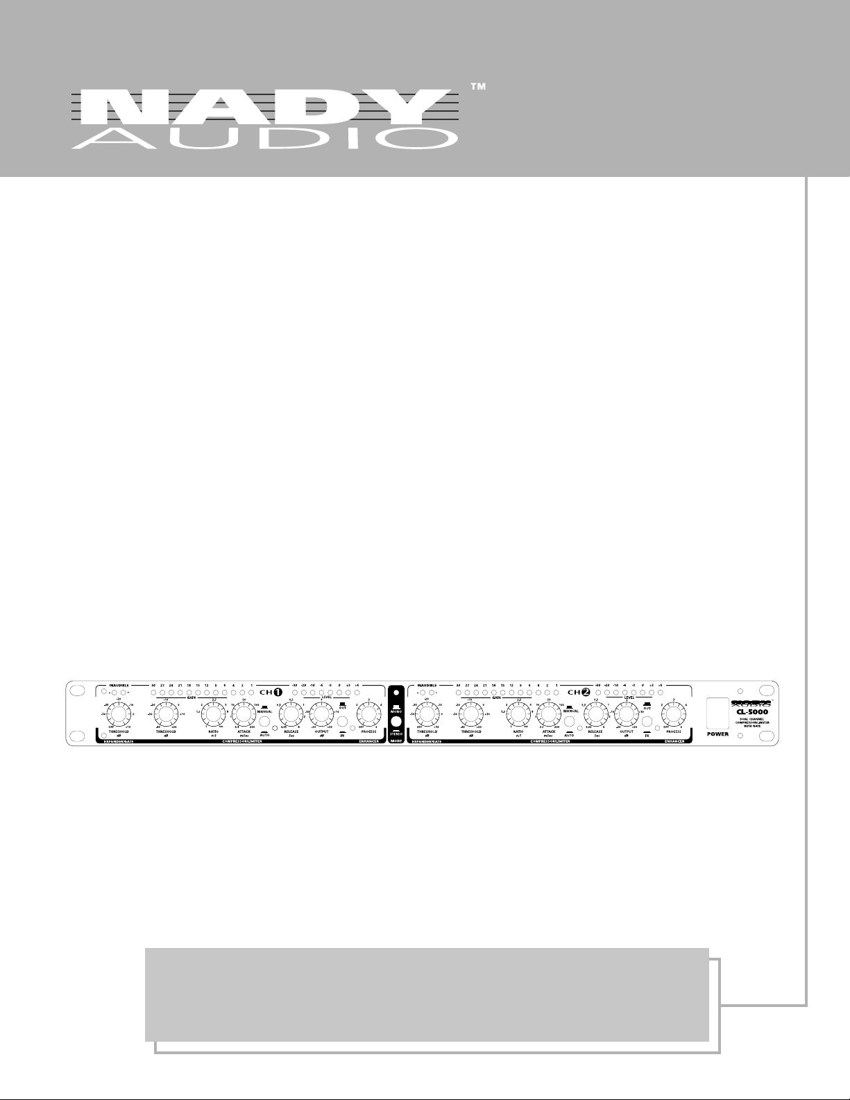
CL-5000
DUAL CHANNEL COMPRESSOR LIMITER WITH GATE
OWNER'S MANUAL
Page 2

CL-5000
DUAL CHANNEL COMPRESSOR LIMITER WITH GATE
Congratulations!
You have just purchased on of the finest professional compressor limiters on the market today. This unit was developed using
the expertise of professional sound engineers and working
musicians. You will find your new NADY AUDIO CL-5000 has
superior performance and greater flexibility than any other
compressor in its price range.
Read this manual carefully to get the most out of your new
unit. Thank you for selecting NADY AUDIO
Date of Purchase
Dealer’s Name
City
State
Zip
Model#
Serial #
Features
• Two independent compressor/limiter/gates in a road-tough steel single-rack-space (1U) housing
• Utilizes a unique circuitry which combines hard and soft knee compression styles, thus providing excellent
inaudible and music program compression as well as providing creative and effective dynamics processing
• Advanced operating features include fully automatic or manually variable attack/release times, compression
ratio, and threshold control
• Dual 12 stage gain reduction and 8 stage input/output metering
• Dual-mono or stereo operation; servo-balanced inputs (with automatic hum and noise reduction) and outputs
• Built-in adjustable dynamic enhancer (selectively replaces high-end loss during even severe compression brought
on by high-energy low-end content)
• IRC (Interactive Ratio Control) expander/gate (which automatically adjusts expansion per the program material,
thus eliminating the noise floor during quiet sections or music pauses)
• TRS side-chain applications, including de-essing, emphasizing/de-emphasizing certain instruments during
recording, eliminating feedback in live applications, and ducking
• Shielded internal power supply and voltage selector for switching between ~115VAC (60 Hz)/~230V AC/(50Hz)
Page 3
An equilateral triangle enclosing a lightning flash/arrowhead symbol is intended to alert the user to the presence of uninsulated “dangerous voltage” within the
product’s enclosure, which may be of sufficient magnitude to constitute a risk of electric shock.
An equilateral triangle enclosing an exclamation point
is intended to alert the user to the presence of important
operating and service instructions in the literature enclosed with this unit.
IMPORTANT SAFETY INSTRUCTIONS
IMPORTANT SAFETY INSTRUCTIONS
WARNING – When using electric products, basic precautions should always be followed, including the following:
1. Read all the instructions before using the product.
2. Do not use this product near water (e.g., near a bathtub, washbowl, kitchen sink, in a wet basement, or near a swimming pool, etc.)
3. This product should be used only with a cart or stand that will keep it level and stable and prevent wobbling.
4. This product, in combination with headphones or speakers, may be capable of producing sound levels that could cause
permanent hearing loss. Do not operate for a long period of time at a high volume level or at a level that is uncomfortable. If you experience any hearing loss or ringing in the ears, you should consult an audiologist.
5. The product should be located so that its location or position does not interfere with its proper ventilation.
6. The product should be located away from heat sources such as radiators, heat vents, or other devices ( including
amplifiers) that produce heat.
7. The product should be connected to a power supply only of the type described in the operating instructions or as marked on
the product. Replace the fuse only with one of the specified type and size and with the correct rating.
8. The power-supply cord should : (1) be undamaged, (2) never share an outlet or extension cord with other devices so that
the outlet’s or extension cord’s power rating is exceeded, or (3) be left plugged into the outlet when left unused for a long
period of time.
9. Care should be taken so that objects do not fall into and liquids are not spilled through the enclosure ‘s openings.
10. The product should be serviced by qualified service personnel when:
A. The power-supply cord or the plug has been damaged; or
B. Objects have fallen, or liquid has been spilled onto the product; or
C. The product has been exposed to rain; or
D. The product does not appear to operate normally or exhibits a marked change in performance; or
E. The product has been dropped, or the enclosure damaged.
11. Do not attempt to service the product beyond that described in the user-maintenance instructions. All other servicing
should be referred to qualified service personnel.
This product may be equipped with a polarized line plug (one blade wider than the other). This is a safety feature.
If you are unable to insert the plug into the outlet, contact an electrician to replace your obsolete outlet. Do not defeat
the safety purpose of the plug.
(For use in the U.S.A.)
IMPORT ANT: THE WIRES IN THIS MAINS LEAD ARE COLORED IN ACCORDANCE WITH THE FOLLOWING CODE.
BLUE : NEUTRAL BROWN : LIVE
As the colors of the wires in the mains lead of this apparatus may not correspond with the colored markings identifying
the terminals in your plug proceed as follows: The wire which is colored BLUE must be connected to the terminal which
is marked with the letter N or colored BLACK. The wire which is colored BROWN must be connected to the terminal which
is marked with the letter L or colored RED. Under no circumstances must either of the above wires be connected to the
earth terminal of a three-pin plug.
(For use in Europe)
Page 4

CONTENTS
A INTRODUCTION ...................................................................................................................................................... 5
B. CONTROLS, CONNECTIONS, OPERATION .............................................................................................................. 6
Expander Gate Section (Operation) ................................................................................................................... 6
Compressor/Limiter Section (operation) ............................................................................................................. 7
Dynamic Enhancer Section (Operation) .............................................................................................................. 9
C. APPLICA TIONS ....................................................................................................................................................... 10
1. MAIN APPLICA TIONS AND INITIAL SETTINGS ............................................................................................. 10
1.1 Compression/Leveling/Limiting/Clipping ........................................................................................... 11
2. EXP ANDER/GA TE SECTION ......................................................................................................................... 12
2.1 Controlling Leakage in the Studio ...................................................................................................... 12
2.2 Initial Settings for the Expander/Gate Section ..................................................................................... 12
2.3 Reducing Leakage in Stage Mics ....................................................................................................... 12
2.4 Reducing Ambient Sound Pickup and Feedback in Stage Mics .............................................................. 13
2.5 Noise Reduction on Effects Paths ....................................................................................................... 13
3. THE COMPRESSOR FUNCTION .................................................................................................................... 13
3.1 Initial Settings for the Compressor Function ........................................................................................ 13
3.2 The CL-5000 as a Sound Effects Unit ................................................................................................. 14
4. THE LIMITER FUNCTION .............................................................................................................................. 14
4.1 Initial Settings for the Limiter Function ................................................................................................. 14
D. SPECIAL APPLICA TIONS ......................................................................................................................................... 14
1. USING THE CL-5000 FOR RECORDING AND CASETTE DUPLICA TION .......................................................... 14
1.1 The CL-5000 in Digital Recording and Sampling ................................................................................. 15
1.2 The CL-5000 in Mastering ................................................................................................................. 15
2. THE CL-5000 AS A PROTECTIVE DEVICE ..................................................................................................... 15
2.1 Protection of a System with a Passive Crossover .................................................................................. 16
2.2 Protection of a System with an Active Crossover .................................................................................. 16
2.3 Improving the Sound of a “Processed” System ..................................................................................... 17
3. USING THE CL-5000 WITH T APE RECORDERS ............................................................................................. 17
4. THE CL-5000 IN BROADCAST ..................................................................................................................... 17
5. USING THE CL-5000 TO CHANGE SOUND ................................................................................................ 17
5.1 Reshaping Sampled Sounds ............................................................................................................... 17
5.2 Altering the T exture of Musical Instruments .......................................................................................... 18
E. EXTERNAL SIDECHAIN APPLICA TIONS .................................................................................................................... 18
1. THE DETECTOR LOOP CONNECTOR ........................................................................................................... 18
2. USING AN EQUALIZER IN THE SIDECHAIN P A TH ......................................................................................... 18
2.1 The CL-5000 as a “De-Esser” ............................................................................................................ 18
2.2 Frequency Selective Filtering of Unwanted Signals .............................................................................. 19
2.3 Suppressing Instruments During Recording .......................................................................................... 20
2.4 Emphasizing Musical Instruments During Recordin .............................................................................. 20
2.5 Reducing Feedback in P A Systems ..................................................................................................... 20
3. ANTICIP A TED COMPRESSION ...................................................................................................................... 21
4. “VOICE-OVER” COMPRESSION (“DUCKING”) ............................................................................................. 21
F. SPECIFICA TIONS .................................................................................................................................................... 22
Page 5

INTRODUCTION
The CL-5000 incorporates several new state-of-the-art circuit designs which make it an extremely efficient and universal dynamics processor: intelligent program recognition, interactive Expander/Gate and a new Dynamic Enhancer.
IKA (Interactive Knee Adaption) Compressor
The IKA (Interactive Knee Adaption) circuitry successfully combines the traditional “Hard Knee” compressor concept with the
“Soft Knee” feature. The “Soft Knee” mode, with its “soft” control characteristics, is the basis of the “inaudible” and “musical”
compression of the program material, while the “Hard Knee” function is a prerequisite both for creative and efficient dynamics
processing and for limiting signal peaks reliably and precisely. This latter function is required to protect subsequent equipment
against distortion, and possible damage.
The Interactive AUTO Processor
The CL-5000 offers an interactive AUTO processor and intelligent program detection. In the AUTO mode, the attack and release
times are derived automatically from the program material, thus effectively eliminating common adjustment errors. This feature
enables optimum results by allowing you to heavily, yet “musically”, compress the signal’s dynamic range without any audible
“pumping”, “breathing” or other side effects.
Manually Adjustable Attack and Release Controls
The response of a compressor and the quality of dynamics processing largely depend on the control times, i.e., the attack and
release functions. When processing signals from individual instruments such as drum, guitar, etc., and when using the compressor to protect the audio system against signal transients, it is imperative that the control times be user- adjustable. The CL-5000
offers this feature by providing both ATTACK and RELEASE controls to allow for variable sound processing.
IRC (Interactive Ratio Control) Expander/Gate
A common problem in using compressors is that the noise floor can be highly amplified during quiet sections or when there are
music pauses. This effect is exaggerated when the compression ratio is inappropriate.
An IRC (Interactive Ratio Control) Expander/Gate has been integrated into the CL-5000. The expansion ratio is automatically
adjusted, dependent on the program material (The response characteristics of conventional expanders tend to cut into the signal
abruptly, often resulting in unacceptably greater attenuation than desired). With the added IRC, the expander is less critical of
adjustment and more tolerant of useable signals only slightly above the noise floor.
Dynamic Enhancer
One of the most common negative effects of compression is the “dulled” or “squashed” sound that is produced when it is
applied to composite music. Since high-energy low frequency instruments cause a compressor to reduce the overall gain, any
high frequency instrument signals occurring simultaneously will also be reduced in level. This “spectral intermodulation” causes
the “squashed” sound effect.
The solution to this problem is the Dynamic Enhancer which allows for selective replacement of high-end loss accrued through
use of compression. Since the Enhancer tracks the amount of compression, enhancement will not be added when no compression is taking place. No altered sound or any additional noise. This feature allows you to apply compression throughout the mix
without any additional outboard enhancer, etc.
The following operational manual will introduce you to the CL-5000 and its various functions. AFTER READING THE MANUAL
CAREFULLY, MAKE SURE IT IS ALWAYS ON HAND FOR FUTURE REFERENCE.
5
Page 6
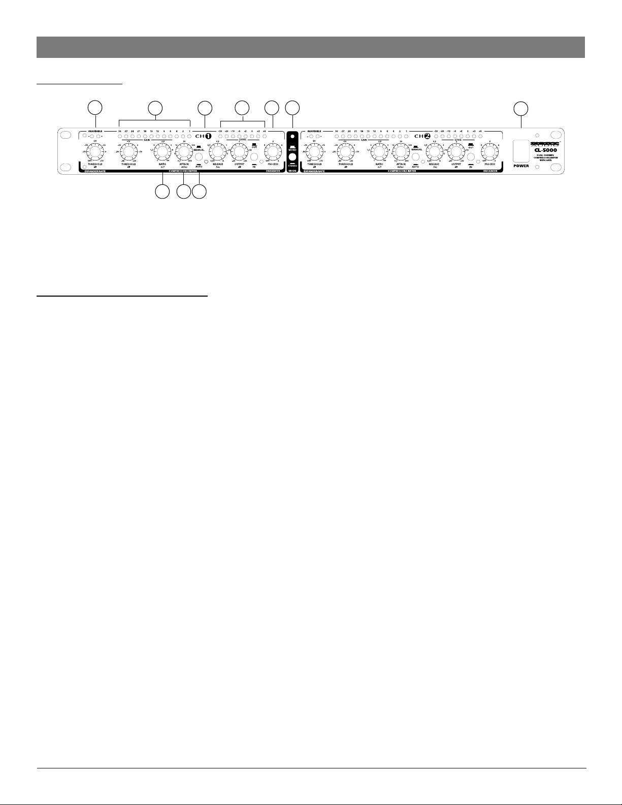
FRONT PANEL
CONTROLS, CONNECTIONS AND OPERATION
39A89B12
710
11
13
1
1. POWER Switch:
This switches the AC power ON or OFF.
Note: In order to avoid possible undesired noise transients in a live sound reinforcement application, switch on the power to
your CL-5000 before switching on the amplification system.
Expander/Gate Section (Operation)
Audio, in general, is only as good as the source from which it was derived. The dynamic range of signals will often be restricted
by noise. synthesizers, effects devices, guitar pickups, amplifiers, etc., generally produce a high level of noise, hum or other
ambient background hiss, which can disturb the quality of the program material. Normally these noises are inaudible if the level
of the desired signal is significantly above the level of the noise. This perception by the ear is based on the “masking” effect:
noise will be masked and thus become inaudible as soon as considerably louder sound signals in the same frequency band are
added. Conversely, the further the level of the desired signal decreases, the more the noise floor becomes a disturbing factor.
Expanders or noise-gates offer a solution for this problem by attenuating signals when their amplitudes drop, thereby fading out
the background noise. Expanders extend the dynamic range of a signal and are therefore the opposite of compressors.
Expansion over the entire dynamic range is not desirable. For example, with an expansion ratio of 5:1 and a processed dynamic range of 30 dB, an output dynamic range of 150 dB would result, exceeding all subsequent signal processors, as well as
human hearing. Therefore the amplitude control is restricted to signals whose levels are below a certain threshold. Signals above
this threshold pass through the unit unchanged. Due to continuous attenuation of the signals below this threshold, this kind of
expansion is termed “downward” expansion.
The noise-gate is the simplest form of an expander. In contrast to an expander, which continuously attenuates a signal below the
threshold, the noise gate cuts off the signal abruptly. In most applications this method is not very useful, since the on/off transition is too drastic. The onset of a simple gate function appears very obvious and unnatural. To achieve an inaudible processing
of the program material, it is necessary to be able to control the signal’s envelope parameters.
The CL-5000 is equipped with an IRC (Interactive Ratio Control) Expander, so that its expansion ratio is automatically adjusted
dependent on the program material. Critical signals in the vicinity of the threshold level are processed with a minute expansion
ratio, whereas signals that reduce in level will be subjected to an increasingly higher ratio, which will result in greater attenuation. The result is expansion, which is less critical to adjust and more tolerant of useable signals whose level is only slightly above
that of the noise floor. Expansion therefore occurs extremely “soft” with low ratio settings, while the known negative effects of
expansion are inaudible. The Attack time of the IRC expander is set automatically and program-dependent, i.e., extremely short
for quickly changing signals and slower for a more balanced program material. Since the expander/gate adapts itself automatically to the program material, you will note that the IRC circuit produces considerably better results than conventional expanders.
2. THRESHOLD Controls:
Use the THRESHOLD controls to determine the threshold point below which expansion occurs. The range of these controls are
from OFF to +10dB.
3. INAUDIBLE Indicators:
For a signal above the threshold value, the “+” LED lights up. For a signal below the threshold, the “-” LED lights up, indicating
expansion mode.
6
Page 7

Compressor/Limiter Section (Operation)
By measuring the dynamic range of musical instruments in live recording situations, you will find that extreme amplitudes will
occur which can lead to overload in subsequent signal processing equipment. In most application, these signal peaks can lead to
heavy distortion. To avoid this kind of distortion or, for example, to prevent loudspeakers from being damaged by overload,
compressors or limiters are used. These devices use automatic gain control to reduce the amplitude of loud passages and
therefore restrict the original dynamics to a desired range. This application is particularly useful in microphone recording to
compensate for level changes caused by varying microphone distances. Although compressors and limiters perform similar
tasks, there is one essential difference. Limiters abruptly limit the signal above a certain level while compressors control the
signal “gently” over a wider range. A limiter continuously monitors the signal and intervenes as soon as an adjustable threshold
level is exceeded. Any signal exceeding this threshold will be immediately reduced back to the adjusted threshold level. A
compressor also monitors the program continuously and has a certain threshold level. However, in contrast to the limiter, signals
exceeding the threshold are not reduced abruptly, but gradually. Above the threshold, the signal is reduced in level relative to
the amount the signal exceeds this point. Generally, threshold levels for compressors are set below the normal operating level to
allow for the upper dynamics to be musically compressed. For limiters, the threshold level is set above the normal operating level
in order to provide reliable signal limiting and thus protect subsequent equipment.
The extensive controls of the Compressor section provide a great range of dynamic effects: from musical and soft compression to
limiting signal peaks, right up to extreme and effective compression of the overall dynamics. For example, a low ratio and very
low threshold setting can be used to achieve soft and musical processing of the general dynamics of the program material.
Higher ratios, together with low threshold settings, create relatively constant volume (leveling) for instruments by preventing the
output level from significantly exceeding the threshold point (provided the OUTPUT controls in the 0 dB position). Please note
that the compression of the entire program material (achieved by low threshold settings) sounds less natural with higher ratio
settings. Ratio settings in the range of 4:1 and lower affect the dynamics of the program material less and are often used to
compress the sound of a bass guitar, a snare drum or a vocal. Sensitive and moderate settings are generally used in mixing and
for leveling of program material in broadcasting.
In the CL-5000, control of the dynamics process is achieved by means of a high quality VCA (Voltage Controlled Amplifier) with
an operating range of about 60 dB, i.e., the input signal level can be reduced or increased within a range of 60 dB. Input signal
levels below the adjusted threshold are not reduced. However, as soon as the input signal exceeds the threshold level, dynamics
control is activated. The amount of compression (gain reduction) is proportional to the amount by which the input signal exceeds
the threshold level. With the threshold control completely turned clockwise, the threshold value is +20 dB. Since such a value will
not be reached in practice, you can use it to disable the compressor section and work exclusively either the expander/gate and
the dynamic enhancer circuits.
Rotate the THRESHOLD control counterclockwise until an appropriate amount of gain reduction is indicated on the GAIN
REDUCTION meter. This operation will be accompanied by an audible drop in output level. The OUTPUT control should now be
turned clockwise to reinstate the output level. Final adjustments of the controls can then be made to suit your particular requirements, including the RATIO, ATTACK and RELEASE controls. The AUTO function of the attack and release times provides program dependent dynamic processing, which suits most standard uses. If a “condensed” or “wider” sound processing technique
is required, the attack and release times can also be manually adjusted.
The experienced user will be in a position to specify parameters while in bypass mode and thus realize the effect before the unit
is actually switched into operation. This is important in live situations, where a signal needs to be managed efficiently by the
sound technician, without the convenience of continuous A/B comparison. For using the Compressor/Limiter as a Limiter, you
should set Ratio turned fully clockwise to
Release times. Use the THRESHOLD control to set the threshold for the limiting level.
∞ :1, switch out the AUTO function and manually adjust short Attack and maximum
7
Page 8

4. THRESHOLD Controls:
The THRESHOLD controls set the threshold point for the compressor sections. They have a range of -40 to +20 dB.
5. RATIO Controls:
The RATIO controls determine the ratio between the input and output level for all signals exceeding the threshold point. The
control range can be adjusted from 1:1 to
output. A ratio of 2:1 indicates, that for every 2 dB increase in input level above the threshold, there will be a corresponding in
increase in output level of 1 dB. Similarly, a ratio of 10:1 indicates that for every 10dB increase in input level above the threshold, there will be a corresponding increase in the output level of 1 dB. If the RATIO control is set fully clockwise, this corresponds
to a ratio of infinity:1. This means that all input levels are reduced to the threshold point and are thus kept constant. (
Although a “hard” or infinite ratio limit has applications in certain specialized situations, in general, this setting is neither
appropriate nor necessary as it would cause audible side effects.)
.
∞ :1. A ratio of 1:1 indicates that the there is no level change between the input and
Note:
6. ATTACK controls:
The ATTACK controls determine the rate by which the compressors respond to a signal exceeding the threshold. These controls
can be adjusted from 0.1 to 200 milliseconds.
(Note: A short attack time is required for very fast transients (level peaks) such as handclaps, snare drums, etc., so that the
compressor is in a position to regulate these types of peaks. With other kinds of program material, it can be advantageous to
apply longer attack times. In fact, it’s always recommended to begin processing with longer attack times and only reduce the
times carefully as required, as the danger of dynamic distortion usually increases with shorter attack times.}
7. RELEASE controls:
The RELEASE controls determine the rate by which the compressors return to unity gain after falling below the threshold level.
These controls can be adjusted from 0.05 to 4 seconds.
the time is incorrectly set, this can lead to 2 fundamental problems: (1) If the release time is too short, the overall volume will
fluctuate when signals peak above the threshold level, giving sound an unpleasant pumping effect; (2) If the release time is too
long, pumping and breathing side effects will result when a loud passage is abruptly followed by a quiet passage.)
(Note: The release time is largely dependent on the program material. If
8. AUTO Switches:
By activating the AUTO switches, the ATTACK and RELEASE controls are disabled and the attack and release rates are automatically derived from the program material by means of intelligent program recognition, so that setting errors can be effectively
avoided. The AUTO processor eliminates side effects such as pumping, modulation distortion, etc., which are found in conventional compressors. This function allows for unobtrusive musical compression of signals or mixes with widely varying dynamics.
The settings of the attack and release controls will function only when these switches are set to MANUAL position.
9A. GAIN REDUCTION Meters:
The 12-segment GAIN REDUCTION meters indicate how effectively the gain is reduced by the compressor, within a range from
1 to 30 dB.
entire range, as in practice, such a broad control range will hardly ever be required. The visual range of the GAIN REDUCTION
meter is thus only 30 dB)
(Note: Although the VCA of the CL-5000 features a control range of almost 60 dB, it is not useful to display the
9B. INPUT LEVEL Meters:
The 8-segment INPUT/OUTPUT meters display the input signal levels to the CL-5000 when the IN/OUT switch (11) is in the OUT
position (bypass). When the IN/OUT switch is set to IN, the INPUT/OUTPUT meter displays its channel signal output level.
10. OUTPUT Controls:
The OUTPUT controls allow for the increase or decrease of the output signals by a maximum of 20 dB. This allows compensation
for a level loss due to the compression or limiting process.
11. IN/OUT Switches:
The IN/OUT switches activate the corresponding channel. This switch acts as a so-called “hard-bypass” so that when the switch
is OUT, the input jack is directly linked to the output jack. Normally, this switch is used to perform a direct A/B comparison
between the unprocessed and the compressed or limited signals.
8
Page 9

Dynamic Enhancer Section (Operation)
Dynamic enhancement allows for selective replacement of high-end loss accrued through use of compression. As the signal level
rises towards the threshold point where compression will occur, high frequency enhancement is added at the same degree to
which the input signal is compressed. The Compressor/Limiter accurately tracks the amount of compression in order to compensate with the same amount of dynamic enhancement, even if there are heavy signal variations. When there is no compression,
the signal is not enhanced. For more versatility, a PROCESS control allows you to control the available amount of dynamic
enhancement.
12. PROCESS CONTROL:
The PROCESS control sets the available amount of enhancement on a relative scale between Off and 6. Dynamic enhancement
allows you to replenish any high frequencies lost through the compression process for absolutely natural sounding dynamics
control. Enhancement is only added when compression is taking place.
13. MODE (STEREO/MONO) Switch:
The MODE switch can be used to select either Stereo or Mono operation as marked. In stereo mode, both channels operate
independently and all the separate channel controls are functional for both channels. In the MONO (depressed button) mode,
the controls of Channel 1 take over all the functions of Channel 2 with the exception of the IN/OUT and the PROCESS control of
the Dynamic Compressor Limiter.
9
Page 10

REAR PANEL
19
115~230V
NADY SYSTEMS, INC.
Emeryville, CA USA
Made in China
17
18
FUSE
T250mAL250V
AC INPUT
CAUTION:
TO REDUCE THE RISK OF FIRE.
REPLACE ONLY WITH THE SAME TYPE
AND RATING OF FUSE
ATTENTION:
UTILISER UN FUSIBLE DE
RECHANGE DE MEME TYPE
DETECTOR LOOP
TIP = INPUT
RING = OUTPUT
SLEEVE =
20
OUTPUT OUTPUT
INPUTS
TIP/PIN2
+4dBu
RING/PIN3
OPERATING
SLEEVE/PIN1
-10dBV
LEVEL
CH 2 CH 1
15 16 14
DETECTOR LOOP
TIP = INPUT
RING = OUTPUT
SLEEVE =
OPERATING
LEVEL
+4dBu
-10dBV
INPUTS
TIP/PIN2
RING/PIN3
SLEEVE/PIN1
14. INPUTS:
The CL-5000 is equipped with both 1/4" (6.3mm) TRS and XLR audio input jacks. These can be used for either balanced or
unbalanced operation as follows: .
Unbalanced use of mono 1/4" plugs: Tip = Signal, Sleeve = Ground / Shield.
Balanced use of TRS stereo 1/4" plugs: Tip = hot (+), Ring = cold (-), Sleeve = Ground / Shield.
Balanced use with XLR connectors: 1 = Ground / Shield, 2 = hot (+), 3 = cold (-).
15. OUTPUTS:
The audio outputs of the CL-5000 are XLR connectors.
Balanced XLR connectors: 1 = Ground / Shield, 2 = hot (+), 3 = cold (-).
16. OPERATING LEVEL Switch:
With the OPERATING LEVEL switch, you can select either of 2 operating levels: the -10 dBV home recording level or the +4 dBu
professional studio level. The level meters are referenced automatically to the selected level so that optimum operating range of
the meters will always be ensured.
17. FUSE HOLDER:
The IEC power socket has an integral fuse holder that takes a 20mm fuse. Always replace a blown fuse with the same type as
specified on the rear of the unit.
18 . POWER CONNECTION:
A standard IEC AC power socket for connecting to the main AC supply with the power cord supplied.
19. AC VOLTAGE SELECTOR Switch:
Use the VOLTAGE SELECTOR Switch to set the unit for the proper voltage for your area, 115 VAC/60 Hz or 230 VAC/50 Hz.
(Note: Selecting the wrong voltage can damage the unt.)
20. DETECTOR LOOP INSERT:
This 1/4" TRS jack can be used as insert point to enable the unit to be controlled externally to operate frequency conscious via
an equalizer. You can use the connector as a pure input (mono jack connector) or as an insert (stereo jack connector). In this
case, use a special insert adapter cable which splits up one stereo into two mono jack connectors. The ring of the DETECTOR
LOOP connector carries the unit’s output signal and the tip receives the processed signal from an external unit.
10
Page 11

APPLICATIONS
In this section, several typical applications of the CL-5000 are discussed. The following basic settings can resolve most dynamic
problems. They are the ideal starting point. Please take the time to study the application examples carefully, in order to be able
to make full use of the capabilities of your CL-5000 in the future.
1. MAIN APPLICATIONS AND INITIAL SETTINGS
The main applications of the CL-5000 can be divided into several categories:
a. The Expander/Gate function is used to eliminate interference and to suppress background noise and leakage on individual
tracks in multi-track recording.
b. The Compressor function is used to compress the program material and to create special effects and unusual sounds, which
are used for recording and musical performance.
c. The Limiter function is designed to protect loudspeakers, tape recorders, transmitters, etc. from signal peaks, sort term
overloading and over modulation (transmitters etc.).
1.1 Compression/Leveling/Limiting/Clipping
Now that the functions and operation of the individual sections and their controls have been explained, we would like to acquaint you with more of the terms and relationships of the dynamics process.
Compression
A compressor converts a large dynamic level into a restricted range. The extent of the resulting dynamic level is dependent on
the threshold, attack, release and ratio settings. As it is the desired effect of a compressor to increase a low level signal, generally the threshold is set low. The “inaudible” compression mode requires fast attack and release times and low ratios. The
fastest the chosen control times and the higher the compression ratio, the greater the effect on the short-term dynamics. This fact
is often used to achieve audible and creative sound effects.
Leveling
The leveling mode is used to keep output level constant, i.e. to compensate for long term gain changes, without affecting the
short -term dynamics. Normally, the threshold is set quite low in order to be able to increase low -level signals. Leveling
requires slow attack and release times, combined with a high ratio. Because of the very slow response time, leveling has no
effect on signal peaks or short-term changes in average level.
Limiting
The limiting function requires a fast attack time and a high ratio and release time setting, which is dependent on the specific use
and the desired sound effect. As it is usually the task of a limiter to limit only high signal peaks, the threshold is usually set at a
high level. The dynamics are reduced dependent on the ratio setting and the degree by which the threshold point was exceeded. If the attack time is adjusted to control only the average level without affecting signal peaks above the threshold, this is
referred to as the program limiter. For this purpose the attack time will be set above 20 ms. If the attack time is further reduced
in order to also control signal peaks, this is defined as a peak limiter.
Clipping
In contrast to the two previously mentioned limiters, the clipping mode features infinitely fast control times, an infinite compression ratio and creates an unsurpassable barrier (“brickwall”) for all signals above a certain level. To be able to control the
signal peaks, the clipping function radically cuts signals above the threshold, without affecting the amplitude of the original
signal. If used in normal applications, this function remains inaudible and under certain circumstances it can even lead to an
improved sound, because cutting the transients creates artificial harmonics. If misused, clipping can cause very obvious and
distasteful distortion, which when taken to the extreme, will convert the signal’s waveform into a square wave signal. This effect
is often produced in guitar distortion devices (“fuzz boxes”).
11
Page 12

2. EXPANDER/GATE SECTION
The main task of the Expander/Gate is to “inaudibly” eliminate undesirable background noise from the usable signal. This
assumes that there is a slight level difference between the usable signal and noise floor, in order to be able to define the operating threshold of the Expander/Gate. At the same time, the Expander/Gate must respond very quickly (have a very fast attack
time) so that the signal’s leading edge remains unaltered.
Because the Expander/Gate of the CL-5000 is self-adapting to the program material, it will be possible to obtain more
satisfactory results with the new IRC (Interactive Ratio Control) circuit than with conventional expanders. When expansion
occurs there are no common side effects due to the extremely smooth and unobtrusive action of the circuit.
When the Expander starts to operate, the INAUDIBLE LED INDICATORS will illuminate. For a signal above the threshold value,
the “+” LED lights. The “-” LED lights when expansion occurs. Because the expansion initially starts very smoothly, you may find
yourself in a situation where this LED illuminates with little or no perceived gain reduction occurring.
2.1 Controlling Leakage In The Studio
Expander/gates are most commonly used to suppress undesirable leakage of sound from one track to another during recording
or playback. They are usually used when recording drum kits, where the mics are very close to each other. High volume levels
of individual instruments often cause considerable leakage onto all the adjacent mics and results in conflicting frequency and
phase coherence problems, as well as unspecified sounds (“comb” filter effects). It is vitally important that every instrument is
recorded into a separate mic and that each mic is individually gated.
Patch the CL-5000 into a snare drum channel for example and adjust it so that triggering only occurs on snare hits. Each mic
should be set to its maximum operating level, monitored and the THRESHOLD level set so the each snare hit sounds acoustically
clean and separate, as though it was played on its own.
The optimum use of the Expander/Gate depends principally on microphone technique. Be particularly careful, when high
frequency instruments are located to the side or rear of a cardioid microphone. Most cardioids exhibit a sharply rising off-axis
response characteristic at higher frequencies. If there is only a 2 or 3 dB difference between the on-axis and off-axis response
in the 5 to 10 KHz region, cymbals may leak excessively into the tom mics and you may have hi-hat spilling all over the snare mic.
Make full use of the directional characteristic of the mics, to acoustically exclude all other instruments as much as possible.
Make sure that you do everything possible to achieve source separation with good microphone technique. Otherwise the
Expander/Gate is not able to undertake clear acoustic separation.
Sometimes, it is necessary to prevent the Expander/Gate from responding to low frequencies (rumbles etc.), especially if a
singer is moving the microphone around on a mic stand. More information about this topic is in section E.2 “Using an Equalizer
in the Sidechain Path”.
2.2 Initial Settings For the Expander/Gate Section
Controls: Settings:
THRESHOLD control: -70 dB
Begin with very low threshold levels, so that the signal can pass through the unit unaffected. Now turn the control clockwise until
all unwanted noise is removed and only the sound of the desired instrument can be heard.
If the control is set correctly, the drum sounds will be “dry”, “sharp” and clearly defined. If you do not have enough mics (or CL5000 channels!) to record each instrument separately, try to create subgroups: put the snare and mid-toms together, and group
the side-toms, bass drum and cymbals together with the help of a mixing console. The aim is to set up the Expander/Gate and
to position the group mics so that each strike on an instrument opens a specific mic and so only that instrument is recorded,
while the other mics remain “muted”.
12
Page 13

2.3 Reducing Leakage In Stage Mics
The CL-5000 has many uses in live sound re-enforcement, on stage and in multi-miking situations: a well set up Expander/Gate
can effectively suppress background noise, compressor type pumping noise and microphone leakage etc., without producing
any undesirable side effects.
Expander/gates are commonly used for processing vocals. When specifically used with a compressor, the distance and position
of the mic in relation to the singer is very critical: the further the distance, the more sensitive the mic is to background noise.
When used in live situations, leakage of miked instrumentation is substantially reduced, as well as other acoustic contaminants in
various recording situations.
2.4 Reducing Ambient Sound Pickup and Feedback In Stage Mics
While singing, a singer’s voice effectively masks most ambient sounds from entering the mic. But in pauses between the singing,
the mic can pick up noise from the house PA and monitors, which can lead to undesired noise and feedback problems. Using
the CL-5000, the mic channel can be shut off when it is not being used, reducing the possibility of noise pickup and feedback.
For best results, all live stage mics should be controlled in this manner.
2.5 Noise Reduction On Effects Paths
The effects rack is one of the main overlooked sources of noise in a PA system or recording facility. The price of reverb, delay
units and harmonizers has fallen drastically over the years, so that now these units are commonly used in even the smallest
studios and home recording installations. However, as multiple effects units considerably increase the overall noise level, care
must be taken to keep the overall accumulated noise level within manageable limits.
Utilizing the noise reduction function of its Expander/Gate section, you will find the CL-5000 indispensable as the last component in the chain of effects units in reducing and eliminating noise in you system.
3. THE COMPRESSOR FUNCTION
The task of a compressor is to reduce the dynamic range of program material and to control the overall level. The extensive
controls of the CL-5000 provide a great range of dynamic effects: from musical and soft compression to limiting signal peaks,
right up to extreme and effective compression of the overall dynamics. For example, a low ratio and very low threshold setting
can be used to achieve soft and musical processing of the general dynamics of the program material. Higher ratios, together
with low threshold settings, create relatively constant volume (leveling) for instruments and vocals. High threshold levels generally limit the overall level of a program. Ratios greater than 6:1 effectively prevent the output level from significantly exceeding
the threshold point (provided that the OUTPUT control is in the 0 dB position).
(Note: The compression of the entire program material (achieved by low threshold settings) sounds less natural with higher ratio
settings. Ratio settings in the range of 4:1 and lower affect the dynamics of the program material less and are often used to
compress the sound of a bass guitar, a snare drum or a vocal. Sensitive and moderate settings are generally used in mixing and
for leveling of program material in broadcast.)
The AUTO function prevents aggressive compression, created by high ratios, from sounding too unnatural.
3.1 Initial Settings For The Compressor Function
Controls: Settings:
THRESHOLD control: +20 dBu
RATIO control: 2.5:1
AUTO switch: Auto (depressed)
OUTPUT control: 0 dB
IN/OUT switch: In (depressed)
Rotate the THRESHOLD control counterclockwise until an appropriate amount of gain reduction is indicated on the GAIN
REDUCTION meter. This operation will be accompanied by an audible drop in output level. The OUTPUT control should now be
turned clockwise to reinstate the output level. The level of the unprocessed and the processed signal can be compared by
13
Page 14

pressing the IN/OUT switch. Final adjustments of the controls can then be made to suit your particular requirements, including
the RATIO, ATTACK and RELEASE controls. The AUTO function of the attack and release times provides program dependent
dynamic processing which suits most standard uses. If a “condensed” or “wider” sound processing technique is required, the
attack and release times can also be manually adjusted.
The experienced user will be in a position to specify parameters while in bypass mode and thus realize the effect before the unit
is actually switched into operation. This is important in live situations, where a signal needs to be managed efficiently by the
sound technician, without the convenience of continual A/B comparison.
3.2 The CL-5000 As A Sound Effects Unit
Since the early 1960’s, musicians have been looking at the recording process as a way to create new sounds. With respect to
compressors, the pumping effect (which had been avoided by earlier recording engineers) suddenly became fashionable and
was often utilized as a creative tool, laying the groundwork for many of the sounds now considered indispensable in contemporary music. The compressor can used in this role because you can hear it working, and, in this instance, control of the dynamic
range is of secondary importance.
The CL-5000, with its extensive range of functions, is well suited to this application. Useful sound effects of this kind can be
achieved using “extreme” settings. To achieve this, set the THRESHOLD control to a fairly low level, the RATIO control to almost
maximum and use the ATTACK and RELEASE controls to obtain the desire effect.
To get the most out of your unit, experiment with all the controls in order to get a feel of their function!
4. LIMITER FUNCTION
In addition to providing a variety of ways to compress signals, the CL-5000 can also be used to limit the overall output level of
the unit and to protect subsequent units from signal peaks, short term overloading and over modulation (transmitters etc.).
4.1 Initial Settings For The Limiter Function
Controls: Settings
THRESHOLD control: +20 dBu
RATIO control:
ATTACK control: 0.1msec.
AUTO switch: Manual (out)
RELEASE control: 0.3 sec.
OUTPUT control: 0 dB
IN/OUT switch: IN (depressed)
Rotate the compressor’s THRESHOLD control counterclockwise until an appropriate amount of gain reduction is indicated on the
GAIN REDUCTION meter. As necessary, the attack and release times can be modified manually.
(Note: Too short attack times can lead to distortion and too long times let dangerous transients pass the unit unhindered. The
RELEASE control should be adjusted to avoid side effects as “fluttering” and “pumping” of the processed signal.)
∞
14
Page 15

SPECIAL APPLICATIONS
1. USING THE CL-5000 FOR RECORDING AND CASSETE DUPLICATION
In the recording and duplication field, the goal should always be to achieve an optimum recording level onto the recording
media. Too low or too high recording levels lead to side effects such as noise, distor tion, etc. In mastering and multi-track
recording, as well as in duplication, one should always take care to utilize the full dynamic range of the tape recorder, DAT
recorder etc. In principal, it is possible to control the recording level by “riding” faders, which means that the gain is increased
with low-level signals, and reduced for high-level signals. It is obvious that this method is insufficient, especially in live recordings, because the expected signal levels cannot be anticipated correctly. Furthermore during multi-track recordings, which are
run under hectic circumstances, the signal level of all channels cannot be monitored and controlled at the same time. Generally,
it is not possible to achieve satisfying recording results using manual control in this way.
An automatic gain control system achieves better and more constant results. Use the CL-5000 by starting with the initial settings,
and use its dynamic control functions to drive either an analog or digital recording noise and distortion free up to the limit of its
maximum dynamic range.
1.1 The CL-5000 In Digital Recording and Sampling
During analog recording, too-low recording levels lead to an increased noise level, whereas too high levels will cause a compressed and “squashed” sound. In extreme cases, loud levels will cause distortion due to tape saturation. In contrast to analog,
side effects in digital recording always become extremely audible: with decreasing levels a tape loses resolution and the recording sounds “hard” and loses “atmosphere”. With excessive level, the recording sounds harsh and heavily distorted. In order to
avoid these effects, the limiter function of the CL-500 should be used. With proper limiting, a digital recording or sampling can
be optimally set to optimum levels without any problem.
1.2 The CL-5000 In Mastering
Mastering is one of the most critical processing steps in recording. During mastering, it is the goal to achieve a “maximum level”
copy of the recording, without any noise or distortion. In many applications it is further required to produce a high average
volume. In the field of commercial media for example, this is apparent especially with records and cassettes processed with high
average volumes. Quite often in these cases, however, dynamics suffer dramatically, because the program material has been
compressed and limited too heavily. Using the combined compressor and limiter functions of the CL-5000 allows you to drastically increase the overall volume, without audibly affecting the dynamics.
Proceed as follows:
1. Limit the dynamics of the program material by 6 dB using the limiter function. By softly clipping just the transients, the real
audio signal will not be limited, resulting in a higher headroom. The overall gain can now be increased by 6 dB, which
leads to a higher volume. More that 6 dB should not be limited, otherwise side effects could become audible.
2. Therefore, in addition, you should also use compression. It is recommended that the compression is limited to the “first” 6
dB of the dynamic range only. A high threshold level in the AUTO mode will generally give good results.
This effect is particularly noticeable with DAT recorders, whose level indicators achieve a response time of less than 1 ms. Set the
DAT recorder at unity and now reduce the THRESHOLD control of the CL-5000 until the GAIN REDUCTION meter indicates a
gain reduction of 6 dB. The “cut” signal peaks cause a reduced recording level of about 6 dB, which is visible on the level
indicators of the DAT recorder. Now increase the recording level of the recorder back to unity. The result is a clearly louder
recording without any loss of sound.
15
Page 16

2. THE CL-5000 AS A PROTECTIVE DEVICE
Sound system distortion is usually a result of amplifiers and loudspeakers being driven beyond their limitations by signals
clipping. This can lead to unpleasant distortion that is dangerous to the speakers.
During normal operation a speaker diaphragm is required to accelerate, slow down, smoothly change direction and accelerate
again. Distorted operation (clipping) leads to instant acceleration, instant stop, change or direction and instant acceleration
again. Since speaker diaphragms are subject to the laws of physics, they will not take this kind of punishment for long: the
diaphragm will either break up or its voice coil may overheat.
In addition to the damage caused by sustained overload, the speaker may also be damaged by an occasional high-level
overload such as, for example, the sound of a microphone falling onto a hard floor. Even if this type of transient does not
destroy a speaker outright, it may damage the speaker in such a way as to cause mechanical abrasion and future failure. It is
recommended that you use the CL-5000 in order to protect your speakers. “Brick Wall” peak limiters are not normally necessary for PA systems, as amplifiers and loudspeakers are tolerant of short signal peaks. Also, conventional limiters have to be
generally driven far beyond the headroom limit of an amplifier in order to limit the level and length of the transients responsible
for overloading the system. The disadvantage of this approach is that the unit’s full range cannot be completely used.
If you increase the average signal level by 3 dB with the CL-5000 limiter function, you effectively double the power amplification. In this way, for example, you can use a CL-5000 to convert a PA system of 5,000 Watts into a distortion-free 10,000
Watts system.
The following instructions will help you to integrate the unit into your system.
2.1 Protection Of A System With A Passive Crossover
If your sound system incorporates a passive crossover network (included in the loudspeaker cabinet), insert the CL-5000 between
your mixing console output and the power amplifier input.
Integrating the CL-5000 into a system with a passive crossover network
16
Page 17

2.2 Protection Of A System With An Active Crossover
For systems using active crossovers there are two ways to use the CL-5000. As shown below, the unit may be inserted between
the console output and the crossover input. In this application, the CL-5000 will process the entire audio frequency spectrum.
Alternately, the CL-5000 can be inserted between the output of an active crossover and the input of a power amplifier. In this
application it will only affect a specific range of frequencies.
The CL-5000 in a two-way System
Compressing the high frequency range with the CL-5000
2.3 Improving The Sound Of A “Processed” System
For our purposes here, let’s define a “processed” system as a PA system with a special active crossover whose outputs are linked
via separate power amplifiers to the loudspeakers. Each band has its own limiter whose task it is to limit dangerous signal
peaks to a certain level. This process avoids overloading the subsequent power amplifier or destruction of the loudspeaker.
In some units, the crossover frequencies in the crossover unit are further changed during high signal levels to achieve a “loud-
ness contour” suited to the human hearing. But in many cases, this function leads more to a disturbance than to an improvement
of the sound quality. If the CL-5000 is preceding this system, the signal peaks can be eliminated before they reach the limiters of
he processing system. The sound quality therefore remains natural and free of side effects caused by the changing frequencies
of the crossover.
17
Page 18

3. USING THE CL-5000 WITH TAPE RECORDERS
The CL-5000 can be used to prevent saturation of magnetic tape and to improve the signal-to-noise ratio of the tape
machine.
In professional recording studios, the saturation level of the tape, system headroom and the output level of the console are
all known quantities, making the application of limiting and compressing very easy. Limiting the audio levels allows for a
higher nominal level of signal to tape, so that the signal-to-noise ratio can be considerably improved.
Using the CL-5000 to avoid distortion due to tape saturation
4. THE CL-5000 IN BROADCAST
The main aim of processing sound recordings for commercial radio and television is to achieve maximum transmission volume at
all costs. This is because radio and television stations strive to get bigger audience ratings, and, as a general rule, listeners
prefer programs that are louder than the average. What is volume? Volume is defined as the relationship between the average
level of program material to peak-to peak level, in response to amplitude and duration. The higher the average level and the
time it remains at a high level, the louder the program material will be perceived by the listener.
If you want to run your broadcast station at maximum average volume, proceed as per section D1.2: “The CL-500 In Mastering”. Please make sure that the maximum peak level is below the threshold of the transmitter’s limiter, otherwise this could lead
to very hard and audible use of the transmission limiters. Keep in mind that a heavy increase in average volume by means of
compression always leads to a loss in dynamics and an increased perception of side effects.
The moderate use of the compressor and the limiter functions of the CL-5000 will result in higher average volumes, free of
distortion.
5. USING THE CL-5000 TO CHANGE SOUND
5.1 Reshaping Sampled Sounds
With the help of the CL-5000, existing or new sampled sounds can be brightened up, changed or used to create new sound.
The attack times and the dynamics of the sounds can be changed as desired.
5.2 Altering The Texture Of Musical Instruments
It would be impossible to mention here all the ways that compression can be used to create new sounds. However, some typical
uses are listed below:
1. Creating a “fatter” snare or kick drum sound
2. “Thickening” acoustic guitars and electric pianos
3. Adding more “punch” to bass guitars
4. Lengthening the sustain of electric guitars etc.
18
Page 19

EXTERNAL SIDECHAIN APPLICATIONS
1. THE DETECTOR LOOP CONNECTOR
The CL-5000 offers exceptionally versatile external control by using the DETECTOR LOOP connector. By using this external
control input, the CL-5000 control path is disconnected from the audio input and therefore interrupted . The audio input is routed
to the DETECTOR SEND output (ring of the DETECTOR connector) and the DETECTOR RETURN input (tip of the DETECTOR
connector) will now receive the new control signal derived from an inserted effects processor.
If you want to use the DETECTOR connector as a control input, just insert a simple mono jack plug. If you intend to use it as a
combined input and output (insert), it is necessary to utilize a special “insert cable”. It splits up one stereo jack plug into two
mono jack plugs and is available in most music stores. The stereo end is used for the DETECTOR connector while the two mono
jack plugs will be connected, for example, to an equalizer. Ensure that your connections are correctly made. The DETECTOR
SEND output should be connected to the input of the equalizer and the DETECTOR RETURN input is routed to the output of the
equalizer.
and outputs are unbalanced. The operating level of external units must be at line level (-20 to +10 dBu) and at unity gain.)
2. USING AN EQUALIZER IN THE SIDECHAIN PATH
It is very common to make the response threshold of a compressor frequency-dependent by connecting a graphic or parametric
equalizer to the sidechain path. To retain the threshold setting of the CL-5000, unwanted frequencies should be reduced by an
equalizer and the desired frequencies should be kept at the same level. Should for example, the compressor be controlled by a
narrow mid-frequency band, it is advisable to lower the bass and treble controls. The middle frequency control remains at unity
gain.
(Note: The wiring for AC powered units must be carefully checked in order to avoid ground loops, as the key inputs
2.1 The CL-5000 As A “De-Esser”
“De-essing” is a special application of frequency selective compression. The sibilant (Ssss) sound of the human voice can often
cause problems during recording. High frequency, sibilant sounds and “pops” can produce very high energy levels which can
sometimes cause an otherwise normal and undistorted voice to sound very harsh, shrill and sometimes unintelligible. The
solution is frequency conscious compression or limiting. The unit responds only to selected frequencies and reduces the level
temporarily, as soon as sibilance or “pops” are detected. If the detector circuit registers an excessive amount of high frequency
information within the program material, as in a normal compressor, the VCA is activated and the overall level is reduced. As
this type of compression affects the whole frequency range, this process is called broadband de-essing.
Please note that this type of frequency selective compression is very different from simple, fixed equalization using notch filters,
since de-essing has no effect on the signal except at the instant the sibilance occurs. The general frequency response is principally not affected during this process.
When de-essing, simply insert an equalizer, not into the audio path, but into the sidechain path of the CL-5000. The equalizer
is inserted between the audio input and the DETECTOR LOOP input of the CL-5000 . The equalizer is now inserted into the
sidechain loop and controls the unit. The center frequencies of the equalizer are then adjusted exactly to match the frequencies
of the sibilant sounds. All other frequencies are filtered out, so that with maximum attenuation of these frequency bands, along
with a correctly adjusted threshold point, the unit responds solely to the selected signal being produced by the equalizer. The
level of the sibilant sounds can therefore be effectively limited
19
Page 20

De-essing using the CL-5000
Initial Settings for the De-Esser Functions
Controls: Settings:
EXP.THRESHOLD CONTROL OFF
THRESHOLD CONTROL +20 dBu
RATIO CONTROL ∞
AUTO SWITCH OUT
ATTACK CONTROL 0.1 msec
RELEASE CONTROL 0.1 sec
OUTPUT CONTROL 0 dB
PROCESS CONTROL OFF
1. Turn the THRESHOLD control counterclockwise until the GAIN REDUCTION meter shows an appropriate drop in level.
2. Now adjust the equalizer’s corner frequencies (generally 6-10 kHz), until it is within the range of the sibilance.
3. Recalibrate the THRESHOLD control, so that the unit reacts only when the sibilant sound occurs.
Level compensation using the OUTPUT control is not necessary. Although the above recommended attack and release times for
this function are proven, the time parameters can be adjusted if necessary to achieve maximum results. The AUTO function
should not be used.
2.2 Frequency Selective Filtering of Unwanted Signals
Based on the set-up described in the de-esser section, the unit may also be used to eliminate rumble, hum and equipment noise
(air conditioning systems, camera noise, etc.). Adjust the frequencies of the equalizer to match the unwanted frequencies and
use a peak filter with a high slope. Take care to decrease the amplitudes of the frequencies you are trying to eliminate. Proceed
now as described in the previous section E 2.1 “The CL-5000 As A De-Esser”. This will result in compression of the selected
frequencies and thus a decrease in the gain of these frequencies in the program mate
2.3 Suppressing Instruments During Recording
The CL-5000 allows useful corrections of previously recorded material. If, for example, an excessively loud bass drum needs to
be suppressed, reduce all the equalizers frequency bands above 150 Hz. This setting causes frequency specific compression,
which reacts as soon as increased energy is detected in this band. By increasing the threshold level, the compression can be
made to react only to loud pedal and stick actions. Generally, it can be said that relatively high threshold settings prevent the
overall sound from being impaired and lead to the compression of solo instruments or very loud sounds.
20
Page 21

2.4 Emphasizing Musical Instruments During Recording
Conversely, you can use the CL-5000 to bring out an instrument solo or a lead vocal in a cluttered mix. Match the frequencies
of the equalizer to the frequencies of the instruments to be emphasized (it is best to use a notch filter with a high slope). (Note:
In this application, make sure you only reduce the amplitude of the selected frequencies.) The compression results in a subjective
decrease in the volume of the overall program material. Only the selected frequencies coming from the equalizer remain
uncompressed and are therefore perceived as being louder. This inverse type of compression also helps to emphasize instruments during low-level passages, so that they become more pronounced.
2.5 Reducing Feedback in PA Systems
A common procedure in sound system set-up is equalizing the acoustics to remove feedback. This is generally accomplished by
turning up the system gain to purposely induce feedback, searching for the center frequency of the feedback and then equalizing at that frequency to remove the feedback. Once this feedback has been attenuated, the system gain is again increased to
induce another feedback point and the whole procedure is repeated until the engineer is satisfied that the relevant problem
frequencies have been corrected. In spite of this equalizing process, feedback remains a difficult problem. Often enough,
acoustic changes occur as the audience enters the room, which again leads to feedback problems. In addition, the frequency
response of the whole system is modified and thus affected by equalizer operation.
Dynamic feedback control is a better solution. Similar to the previously mentioned de-esser application, an equalizer is not
inserted into the audio path but into the sidechain path of the CL-5000. To effectively suppress feedback, the center frequency of
the equalizer is correctly adjusted to match the room’s resonant feedback frequency. This selected frequency now controls the
CL-5000. The signal coming from the equalizer is applied to the DETECTOR LOOP input, while the audio signal is routed
through the CL-5000 audio path. As soon as feedback occurs, the unit temporarily reduces the system gain and thus effectively
suppresses the feedback. In contrast to the technique mentioned above, the frequency response of the PA system is not affected
in any way at all. The use of the CL-5000 in this application can eliminate the possibility of speaker or ear damage.
21
Reducing feedback in audio systems using the CL-5000
Page 22

3. ANTICIPATED COMPRESSION
If you feed the audio signal directly into the DETECTOR LOOP input and send the audio signal through a delay before the audio
input, the CL-5000 can anticipate the need for gain change. With experimentation, the effect can create a “zero” attack time at
a given frequency. Additional delay beyond this “zero” attack time will produce a special sound effect, similar to the dynamic
envelope inversion you may already be familiar with from reverse tape playback.
Anticipated compression using the CL-5000
4. “VOICE-OVER” COMPRESSION (“DUCKING”)
The CL-5000 can be used to automatically reduce music to background level when an announcer is speaking through a microphone. For this purpose, the CL-5000 is used as an automatic fader and is controlled by the announcer’s microphone, which is
connected to the DETECTOR LOOP, input via a preamplifier. The music output and the announcer’s voice, are then mixed. This
application is known as “voice-over” compression or “ducking” and is commonly used in discos, radio stations, etc.
“Voice-over” compressing using the CL-5000
22
Page 23

SPECIFICATIONS
INPUT
Type RF filtered, servo-balanced input
Connectors XLR and 1/4" TRS jacks
Impedance 50K Ohms balanced, 25K Ohms unbalanced
Nominal Operating Level +4 dBu / -10 dBV switchable
Max. Input Level +21 dBu balanced and unbalanced
CMRR typically 40dB, > 55dB @ 1kHz
DETECTOR INPUT
Type DC de-coupled unbalanced input, 1/4” TRS jack
Impedance > 20K Ohms
Max. Input Level +21 dBu
OUTPUT
Type Electronically buffered output stage
Connectors XLR jacks
Impedance 60 Ohms balanced, 30 Ohms unbalanced
Max. Output Level +21dBu balanced and unbalanced
Bandwidth 20Hz to 20kHz, +0/-0.5dB
Frequency Response 0.35 Hz to 200kHz, +0/-3dB
Noise > -95dBu, unweighted, 22Hz to 22kHz
THD 0.04% typically @ +4dBu, 1kHz, Gain 1
IMD 0.01% typically, SMPTE
Crosstalk < -100 dB, 22Hz to 22kHz
Stereo Coupling True RMS detection
CMR@ 1 KHz > 60 dB
EXP ANDER/GATE SECTION
Type IRC (Interactive Ratio Control) Expander/Gate
Threshold variable (OFF to +10 dBu)
Attack < 1 ms/100 dB
Release 100 ms/ 100 dB
COMPRESSOR SECTION
Type IKA (Interactive Knee Adaption) Compressor
Threshold variable (-40 to + 20 dBu)
Ratio variable (1:1 to
Threshold Characteristics Hard Knee
Manual Attack Time variable (0.1 to 200 ms/20 dB)
Manual Release Time variable (0.05 to 4 sec/20 dB)
Auto Attack Time typ. 15 ms. @ 10 dB, 5 ms @ 20 dB, 3 ms @ 30 dB
Auto Release Time program dependent, typ. 125 dB/sec.
Output variable (-20 to + 20 dB)
∞ :1)
DYNAMIC ENHANCER SECTION
Type Dynamically controlled frequency correction
Process variable (OFF to 6)
FUNCTION SWITCHES
IN/OUT Bypass switches both channels
Auto Program-dependent attack and release times
23
Page 24

INDICATORS
12 segment GAIN
REDUCTION meter 1/2/4/6/9/12/15/18/21/24/27/30 dB
8 segment LEVEL meter -30/-20/-10/=6/-3/0/+3/+6 dB
LED indicator for each function switch
INAUDIBLE LEDs “+”/”-” indicates onset of the Expander/Gate
POWER SUPPL Y
AC Voltage 100-120/60HZ or 200-240/50HZ VAC selectable
Power consumption 9 watts
Fuse T250mA, 250V
Power Cord Connector Standard IEC receptacle
DIMENSION 1.75" X 19" X 7.8" (44 X 482 X 197mm.)
WEIGHT 7.04 lbs. (3.2 Kg.)
For improvement purposes, modifications may be made from time to time to this product without prior notice, so specifications and appearance may differ from those listed or shown.
24
Page 25

SERVICE
(U.S.) Should your NADY AUDIO product require service,
please contact the Nady Service Department via phone
at (510) 652-2411 or E-mail at service@nady.com.
(INTERNATIONAL) For service, please contact the
NADY AUDIO distributor in your country through the
dealer from whom you purchased this product.
DO NOT ATTEMPT TO SERVICE
THIS UNIT YOURSELF AS IT CAN
BE DANGEROUS AND ALSO WILL
VOID THE WARRANTY.
NADY SYSTEMS, INC. • 6701 SHELLMOUND STREET • EMERYVILLE, CA 94608
Tel: 510.652.2411 • Fax: 510.652.5075 • www.nady.com
' 2000 NADY SYSTEMS
 Loading...