

Page 1
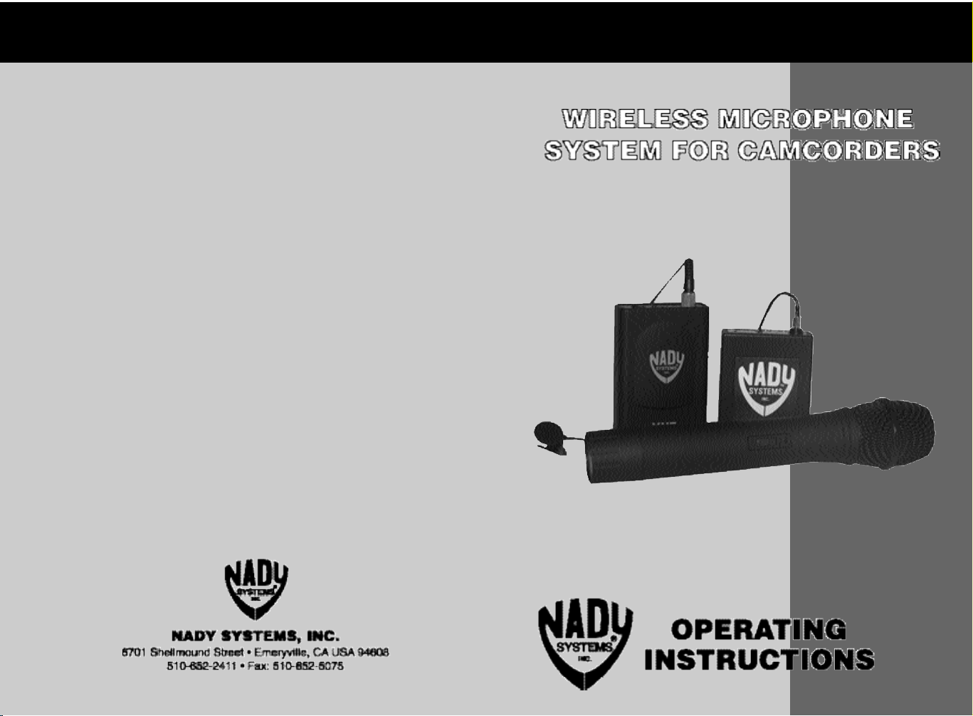
NADY 351 VR
NADY 351 VR
Page 2

S P E C I F I C AT I O N S
Overall System Performance
Frequency Response ....................................................................................25 - 20,000 Hz ± 3 dB
Operating Frequency Range........................................Choice of 5 channel between 170-216 MHz
Dynamic Range ..........................................................120 dB (max SPL to A-weighted noise level)
Harmonic Distortion ..............................................................................................................< 0.3%
Frequency Stability ..................................................................................±.005%, crystal controlled
Modulation ..................................................................................................................FM, ± 15 KHz
Operating Range ......................................................Up to 250 feet (depending on site conditions)
351 VR Receiver
Controls ......................................................Headphone volume controls with unit OFF/ON switch,
Audio output ....................................................................................................600 ohm unbalanced
Connectors ..............................Audio output; 3.5 mm mini jack; Headset output; 3.5 mm mini jack
LED Indicators .............."TX" on; “LOW BATT”: unit "ON" (single flash), Low Batter y Alert (steady)
Mute ............................................................................Externally adjustable; 1 µV preset minimum
Unwanted Signal Rejection ....................................................................60 dB image and spur ious
Power Requirements ..............................................................................Single 9V alkaline, internal
Antenna ............................................................................................................Softwire, detachable
Mute adjust, Audio output level adjust
WLT Lavalier Bodypack Transmitter
Audio Input ..............................3.5 mm mono locking jack for connecting to omni or unidirectional
Controls ......................................................................OFF/STANDBY/ON switch, input level adjust
LED Indicators..................................................Unit "ON" (single flash), Low Battery Alert (steady)
RF Power Out..........................................................................50 mW (maximum allowed by FCC)
Harmonic and Spurious Emissions ....................................................................................> -40 dB
Battery ............................................................................................................................9V alkaline
Battery Life ................................................................................................................Up to 15 hours
lavalier mic or unidirectional head worn mic, with phantom power.
WHT Handheld Microphone Transmitter
Audio Input................................................................Nady DM-10D neodymium dynamic cartridge
Controls ..................................................................................................OFF/STANDBY/ON switch
LED Indicators..................................................Unit "ON" (single flash), Low Battery Alert (steady)
RF Power Out..........................................................................50 mW (maximum allowed by FCC)
Harmonic and Spurious Emissions ....................................................................................< -40 dB
Battery ............................................................................................................................9V alkaline
Battery Life ................................................................................................................Up to 15 hours
S e r vice for your Nady Wi reless System
( U . S . ) Should your wireless system require serv i c e, please contact the Nady Service Depart m e n t
via telephone at (510) 652-2411 or e-mail to serv i c e @ n a d y.com for a Return Au t h o rization (R/A)
Number and a service quote (if out of wa r r a n t y ) . M a ke sure the R/A Number is clearly marked on
the outside of the package and enclose a cashier's check or money order (if not prepaid with a
credit card). Ship the unit prepaid to: Nady Systems, Inc., Service Department, 6701 Shellmound
Street, Emery v i l l e , CA 94608. Include a brief description of the problem you are ex p e r i e n c i n g .
The warranty card enclosed with this system contains additional va l u a ble warranty and
s e rvice info r m a t i o n . Keep it in a safe place for possible future refe r e n c e. Do not attempt to
s e rvice this unit yo u r self as it will void the warranty.
( I n t e r n a t i o n a l ) For serv i c e , please contact the Nady distri butor in your country through the dealer
from whom you purchased this product.
TABLE OF CONTENTS
Using this Manual..................................................................3
351 VR Receiver ..................................................................4
WLT Lavalier Bodypack Transmitter ......................................6
WHT Handheld Microphone Transmitter ..............................8
Specifications ......................................................................10
Service ................................................................................10
Thank you for purchasing a Nady 351 VR wireless camcorder microphone
system—and congratulations on your choice. The 351 VR operates on longrange interference-free VHF high band frequencies. It also utilizes a patented
companding noise reduction system for excellent dynamic range (120 dB) and
hiss-free perfo r m a n c e . The 351 VR will make a tremendous difference in yo u r
v i d e o s , adding professional quality audio to eve r y production.
Using this Manual
Please read these instructions completely before operating your unit. T h i s
booklet gives instructions for the operation of the Nady 351 VR wireless
system which consists of a wireless receive r, an audio cord to connect the
r e c e i v er to your camcorder, and a wireless microphone transmitter—either the
W LT lavalier or Nady WHT handheld.
10
3
Page 3

NADY 351 VR RECEIVER
• Ultra-compact receiver can be camera mounted or worn on the body (with
attached clip).
• Easy hookup to camcorder with supplied connecting cable
• Powered by a 9V Alkaline battery in a convenient “slide open” battery
compartment
• LED lights indicate low battery and receiver signal
• Detachable softwire antenna extends from the top of the receiver
• Convenient operation with Output Level and Mute Adjusts, separate
3.5mm Audio Output and Monitor Headphone mini jacks and Headphone
Volume thumbwheel control with integrated unit OFF/ON switch
Operating Instructions
Powering the Receiver
Slide the receiver’s battery cover open and place a fresh 9V battery in the
BATTERY COMPARTMENT (1), observing the correct polarity. (Although a
fresh alkaline battery can last up to 8-10 hours in use in the receiver, in
order to ensure optimum performance it is recommended that the receiver
battery be replaced after 5 hours use.) Turn the receiver on by rotating the
ON/OFF/VOLUME WHEEL (2) clockwise. The LOW BATT LED (3) will
flash briefly, indicating adequate battery strength. If the LOW BATT LED
lights during use, replace battery.
Antenna
When the system is in use, the 351 VR receiver’s standard wire Antenna
should be fully extended to obtain maximum range. You may also install
Nady’s optional rubber duck or flexible rubber duck antenna. They all simply
screw into the ANTENNA SOCKET (4) on top of the receiver.
Battery Indicator LED
(21)
(20)
OFF/STANDBY/ON Switch
Mute Adjustment
In normal operation, the MUTE CONTROL (5) on the back of the receiver
should be set fully clockwise to the factory preset RF level of 1 µV.
However, in areas of high RF activity, the mute may need to be adjusted. If,
with transmitter off, the receiver’s “TX” LED (6) flickers or stays on, the
MUTE control should be turned counter clockwise until the “TX” LED
extinguishes.
When the mute is properly adjusted, the “TX” LED will light only when the
system transmitter is turned on.
clockwise will yield a quieter mute function, but reduce your operating range.
Note: Turning the MUTE control too far counter
4
(18)
Battery Holder
(19)
9V Alkaline Battery
9
Page 4

WHT HANDHELD MICROPHONE TRANSMITTER
• Features the Nady DM-10D unidirectional neodymium dynamic cartridge
for optimum true sound, maximum feedback rejection and minimal
handling noise
• OFF/STANDBY/ON switch allows convenient audio muting with the
transmitter "ON"
• Low battery LED indicator flashes once for unit "ON"; lights steady for low
battery alert
Connecting Audio Output
Plug one end of the audio cable provided into the AUDIO OUTPUT JACK
(7). The other end should be plugged into your camcorder.
Connecting Headphone to Monitor
You can monitor the received signal through headphones, and you will need
to monitor to set the transmitter’s level trim properly. Any “Walkman” type
headsets with a minijack or minijack adaptor can be used, though the signal
may be heard in only one ear unless a stereo-to-mono adapter jack is used.
Operating Instru c t i o n s
1 . U n s c r ew the BAT T E R Y COMPA R TMENT COVER (18) and remove,
exposing the battery holder. I n s e r t a fresh 9V ALKALINE BAT T E R Y (19),
o b s e r ving the correct polarity as marked, and screw the cover back on to the
m i c r o p h o n e . M a ke sure the cover is screwed on completely. A fresh alkaline
b a t t e r y can last up to 15 hours in use, but in order to ensure optimu m
p e r f o r m a n c e , it is recommended that you replace the battery after eve r y 10
hours of use.
2 . Tu r n on the WHT by sliding the O F F / S TANDBY/ON SWITCH (20) to the
S TANDBY position (transmitter on, audio muted) or the ON position
( t r ansmitter and audio both on). The BAT T E RY INDICATOR LED (21) w i l l
g i ve a single quick flash, indicating usable battery strength. In the case of a
dead or low battery, the LED will either not go on at all or will stay on
c o n t i n u o u s l y, indicating that the battery should be replaced with a fresh one.
To preserve battery life, turn the transmitter off when not in use.
3 . The microphone is now ready to use. The TX LED (6) on the 351 V R
r e c e i v er should now be lit, indicating a received signal from the tra n s m i t t e r.
When ready to speak, slide the transmitter switch to the ON position.
Receiver Volume Control Adjust
Turn volume control on the 351 VR receiver clockwise to near full gain.
Wearing a monitor headset plugged into the receiver's headset jack, speak
into the lavalier microphone. Adjust the receiver's volume to a comfortable
listening level.
N o t e : Microphone elements can easily be destroyed by the buildup of salts and minerals from
p e r s p i r ation and saliva . It is good practice to put a windscreen on the mic element at all times to
protect it.
Monitoring through Receiver
Plug headphones into HEADPHONE JACK (8) on the receiver. The
ON/OFF/VOLUME WHEEL (2) controls volume to the headset. Set the
volume to a comfortable level by rotating the volume wheel.You will be able
to hear the received signal to the receiver when the system is operational.
This is the monitoring method necessary when adjusting the WLT-15
transmitter’s microphone input level per page 6.
Monitoring through Camcorder
Many camcorders allow the user to monitor by providing a headphone jack. If
you plug your headphones into the camcorder, you may need to make a
simple adjustment on the 351 VR receiv er. If the sound you hear is
uncomfortably loud or sounds distor ted, turn the AUDIO LEVEL CONTROL
(9)
(5)
(7)
(4)
( 9 ) on the back of the
r e c e i ver counter-clock w i s e
until good audio quality is
obtained. If volume is too low,
t u r n the AUDIO LEVEL
(2)
(8)
(3)
C O N T ROL (9) c l o c k w i s e
until you obtain comfortable
volume.
Transmitter Set-Up
After completing the above
steps, proceed to instructions
(1)
(6)
for operating the Nady transmitter included with yo u r
system.
8
5
Page 5

WLT LAVALIER BODYPACK TRANSMITTER
• OFF/STANDBY/ON switch allows convenient audio muting with the
transmitter “ON”
• Low battery LED indicator flashes once for unit “ON”; lights steady for low
battery alert
• Locking 3.5mm mini-jack provides secure connection for removable
microphone or instrument cable
• Easily accessible input level adjust control for optimum sound
Operating Instructions
1. Snap open the BATTERY COMPARTMENT (10) and insert a fresh 9V
BATTERY (11), observing the correct polarity. Close the compartment.
2. The WLT is provided with a 3.5 mm LOCKING JACK (12) for connecting
the microphone. Plug in either the LAVALIER/LAPEL (13) or the
HEADWORN MICROPHONE (14), as supplied. To secure the connection,
turn the metal slip ring on the plug clockwise to thread it on to the jack. To
unplug, reverse the process. Slip the transmitter into a pocket or clip on to
your clothes. To use the lavalier mic, attach it at chest level. Do not place
too close to the mouth – a distance of about six inches usually works best.
To use the headworn mic, place it on the head and adjust the mic boom so
that the mic is about one inch to the side of the front of the mouth.
(Note: The lavalier or headworn mic wire is also the transmit antenna, and rolling up or
shortening the wire may reduce the effective operating range. Extend the wire fully during use,
and keep it as straight as possible.)
3. Turn on the WLT by sliding the OFF/STANDBY/ON SWITCH (15) to the
STANDBY position (transmitter on, audio muted) or the ON position
(transmitter and audio both on). The BATTERY INDICATOR LED (16) will
give a single quick flash, indicating usable battery strength. In the case of a
dead or low battery, the LED either will not go on at all or will stay on
continuously, indicating that the battery should be replaced with a fresh
one.
(Note: Microphone elements can easily be destroyed by the buildup of salts and minerals from
perspiration and saliva. It is good practice to put a windscreen on the mic element at all times to
protect it.)
(17)
Audio Input
Level Control
(16)
Battery Indicator LED
(15)
OFF/STANDBY/
ON Switch
Lavalier/Lapel
Compartment
3.5 mm
Locking Jack
(13)
(10)
Battery
(12)
(14)
Headworn
Microphone
4. The microphone is now ready to use. The TX LED INDICATOR (6) on
the 351 VR receiver should now be lit, indicating a received signal from the
transmitter. When ready to speak, slide the transmitter switch to the ON
position and adjust the volume of the receiver as per instructions on page
5. Re-position the microphone farther from the source or adjust the AUDIO
INPUT LEVEL CONTROL (17) if the monitored volume is to loud or
distorted afer adjusting the receiver as per instructions on page 5.
6
Opening Battery Compartment
(11)
9V Alkaline Battery
7
 Loading...