

NADEX MDM22 User Manual

Handy Nadescorder
MDM22 -M01A
Instruction Manual
----- Important -----
Please read this instruction manual before starting to use your device. You may risk accidents
if you use it without observing the instructions in the manual.
Safety instructions in this manual are presented with the following marks according to the
degree and kind of danger involved:
DANGER
Failure to observe the warning with this mark greatly increases the possibilities of accidents
that can result in death or serious injury.
WARNING
Failure to observe the warning with this mark may present the possibilities of accidents that
can result in death or serious injury.
CAUTION
Failure to observe the caution with this mark may result in injuries or physical damage.
This mark indicates that improper handling may create shock hazards.
This mark indicates that improper handling may lead to troubles caused by poisonous
substance.
This mark indicates that improper handling may cause injury or other troubles.
This mark indicates that improper handling may create fire hazards
This mark indicates that improper handling may lead to an explosion.
This mark indicates that improper handling may lead to troubles due to high temperatures.
This mark indicates that use in a shower or outdoor use in the rain is forbidden.
This mark indicates that disassembly or remodeling is forbidden.
This mark indicates that the power plug must be disconnected from the wall outlet.
This mark indicates cautions other than the above.
Read First For Your Safety
In case you use it in order to have you use it safely, be careful of the following things.
Failure to observe the safety precautions can cause accidents that may damage the
equipment or inflict injuries or death on the user or people around.
DANGER
1. Avoid damaging cords and cables by leading them under the machine or getting
them caught between objects. Otherwise the electric wire may short-circuit to
cause electric shock, leak or fire.
When disconnecting a cord or cable, be sure to do so by holding the plug or
connector. Otherwise the cord or cable may have a break, which will eventually
develop into functional failure, overheating or fire.
2. Be sure to use the charging AC adapter supplied with the equipment. Use of
another AC adapter may not only lead to failure of the equipment but also
cause fire or explosion due to abnormal heating.
3. Take special care during charging when both the equipment and the AC adapter
heat up. Never place paper or cloth on the equipment and AC adapter during
charging. To prevent fire, be sure to charge the equipment in a cool, well-ventilated
place.
WARNING
1. Give adequate care to safety in wiring the cables. Be sure to install them where
they will not interfere with robot operation or the movement of workers.
2. Be sure to use the cables supplied with the equipment for connection with other
equipment such as a printer. Otherwise faulty operation or functional failure may
occur.
3. For use and storage of this equipment, avoid locations where it can be exposed to
sunshine, dust, rain water or excessive humidity.
4. Place the equipment on a stable floor. Locating it at an elevated or unstable place
can result in injuries from the drop of the equipment.
5. A battery pack should not carry out decomposition and reconstruction.
If it decomposes and converts, it may generate heat, ignite or explode.
6. Please do not add a strong shock to a battery pack. Moreover, please charge by the
method of handling description specification.
If a shock is added or it charges by methods other than specification, it may generate
heat, ignite or explode.
7. Please do not put in a battery pack into fire.
If it puts in into fire or heats, it may explode or explode.
8. Changes or modifications not expressly approved by the manufacturer for
compliance could void the user's authority to operate the equipment.
9. In order to comply with FCC radio-friquency radiation exposure guidelines for an
uncontrolled exposure, this device and its antenna must not be co-located or
operating in conjunction with any other antenna or transmitter.
10. The term "IC:" before the radio certification number only signifies that Industry
Canada technical specifications were met.
"Operation of this device is subject to the following two conditions: (1) this device
may not cause interference, and (2) this device must accept any interference,
including interference that may cause undesired operation of the device."
"The installer of this radio equipment must ensure that the antenna is located or
pointed such that it does not emit RF field in excess of Health Canada limits for
the general population; consult Safety Code 6, obtainable from Health Canada's
website www.hc-sc.gc.ca/rpb"
CAUTION
1. The product that you have purchased contain a rechargeble battery.
The battery is recyclable. At the end of its useful life, under various state and local
laws, it may be illegal to dispose of this battery into the municipal waste stream.
Check with your local solid waste officials for details in your area for recycling
options or proper disposal.
So please consult your NADEX dealer about the way you dispose of used batteries.
2. For a long period of disuse, store the equipment with the charging AC adapter and
other appendent units disconnected from it.
3. Never engage in disassembly, remodeling or unwarranted adjustment of this
equipment. Tinkering with this equipment may cause equipment failure or
malfunction.
4. Do not use a volatile fluid, such as benzene or thinner, when wiping the equipment
clean. Use of such a fluid can cause the deformation or discoloration of the casing.
5. Do not use this equipment for purposes other than as a welding current meter.
NADEX does not hold itself responsible for any equipment failure resulting from
use for purposes other than specified.

Contents
1. Outline ........................................................................................ 1
2. Names and Functions of Components ........................................ 2
3. Composition................................................................................ 4
4. Measuring Method...................................................................... 5
4-1. Measurement Operation Procedure............................................................... 5
4-2. The display of a liquid crystal display............................................................ 7
4-3. Notes on the Use of CT Coil............................................................................ 9
4-4. Note on the Use of Tip Voltage Detection Cable ......................................... 10
5. Selection of Menu Function ..................................................... 11
5-1. How to select................................................................................................... 11
5-2. Selection Menu Items..................................................................................... 11
6. Communication Method ........................................................... 16
6-1. In the Case of USB......................................................................................... 1 6
6-2. In the case of radio communications (Bluetooth) .......................................16
7. How to Charge.......................................................................... 18
8. Error Display ............................................................................ 19
9. Troubleshooting........................................................................ 20
10. Specification ........................................................................... 22

Outline
1. Outline
This machine is a welding current meter capable of measuring the welding current, welding cycle and
tip voltage of resistance welders and displaying measured values on the liquid crystal display. The
device presents the following features:
1) The equipment is small and lightweight, so that it can be easily carried around within the factory
premises.
2) A large capacity memory allows storage of up to 10000 average data, 20 each cycle / each msec
data and 1 newest waveform data.
3) Data is transmitted to a personal computer and data processing is possible with a personal computer.
(The exclusive software for personal computers is required)
4) Since the charge battery is built in, it is cordless and can be used.
5) Collection of the data in remoteness is possible by radio communications (Bluetooth).
6) The connectors for the cables used are all easy-to-use "one-touch" connectors.
7) There are two measuring ranges, namely, Lo:2.50 to 19.99kA and 10.00 to 49.99kA. You can
select a range best suited to the current levels you are going to measure.
8) The WELD lamp lights up when welding is being detected. Therefore, measuring condition can be
monitored even when you are away from the welding machine.
9) The equipment can be used not only with AC welder but also with DC welder, inverter controlled
welder, and AC inverter controlled welder.
10) Current consumption is minimized by the auto power-off function, in which power is turned off
automatically when there is no key operation, welding.
( [ 10 minutes ], [ 30 minutes ], [ 60 minutes ], and auto-power-off function (OFF))
1 / 24
Names and Functions of ComponentsNames and Functions of Components
Names and Functions of Components
Names and Functions of ComponentsNames and Functions of Components
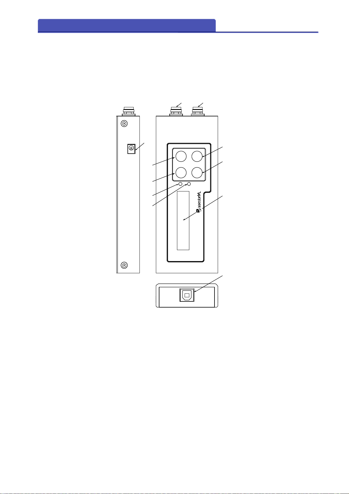
2. Names and Functions of Components
2 / 24
(10)
(1)
(2)
(9)
(5)
POWER
DISP
WELD
(6)
(4)
SEL.MENU
CHARGE
(3)
(7)(8)
Handy Nadescorder
(11)

Names and Functions of ComponentsNames and Functions of Components
Names and Functions of Components
Names and Functions of ComponentsNames and Functions of Components
(1) [POWER] key
Turns power on and off.
(2) [DISP] key
Operate this key when changing displays or when switching from menu mode to measurement
mode.
(3) [MENU] key
Operate this key when changing menu items or when switching from measurement mode to menu
mode.
(4) [SEL.] key
Use this key for setting change of menu item.
The lighting for LCD turns on at the time of a measured value display.
(5) The connector for current measurement
Connect the appendant CT cable.
(6) The connector of voltage between tips
Connect the appendant tip voltage cable.
(7) Liquid crystal display
Measured value is displayed in measurement mode.
The contents of a menu are displayed in menu mode.
(8) WELD lamp
Lights up when welding is being done and goes out when it is completed.
(9) CHARGE lamp
Lights up during charging. 7. Refer to the Charge Method.
(10) Power supply jack
Connect the supplied AC adapter when charging.
(11) USB connector
Connect the USB cable when performing cable communications.
3 / 24
Composition
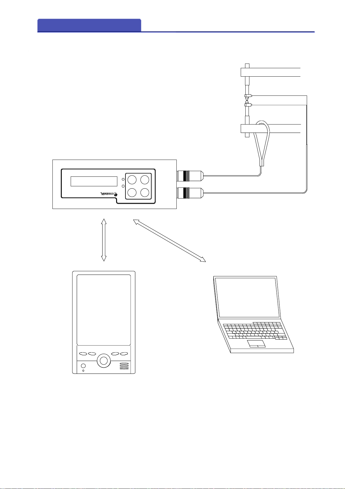
3. Composition
4 / 24
welding machine
Handy Nadescorder
Handy Nadescorder
Radio communications
(Bluetooth)
WELD
WELD
WELDWELD
CHARGE
CHARGE
CHARGECHARGE
DISP
DISP
DISPDISP
MENU
MENUMENU
POWER
SEL.
SEL.MENU
SEL.SEL.
CT
Tip voltage detection cable
Radio communications
(Bluetooth)
or USB
PDA PC
 Loading...