

Page 1

Page 2
Page 3

Page 4
Page 5
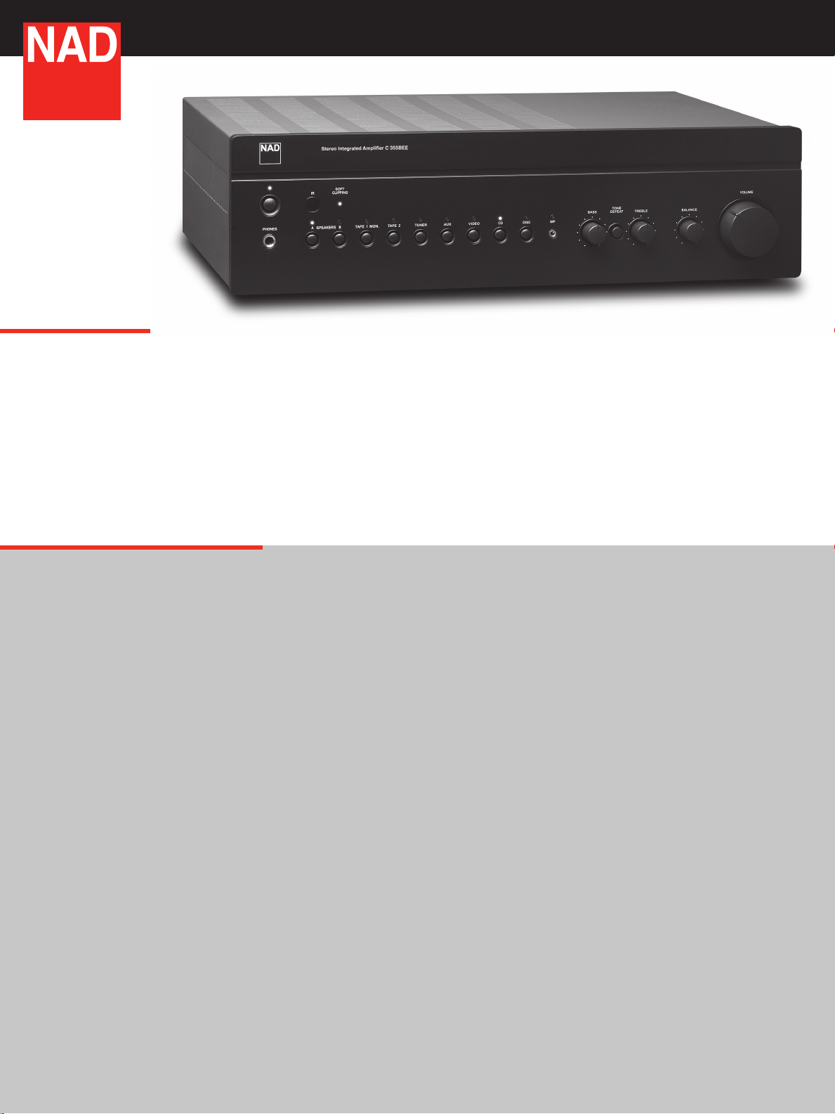
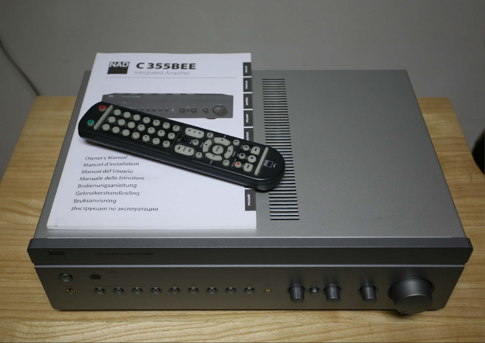
C355BEE Stereo Integrated Amplifier
Features
• 80Wx2ContinuousPowerinto8ohms
• 140W,220W,270WIHFDynamicpowerinto8,4and2ohms,
respectively
• PowerDrive™circuit
• NADSR5FullSystemRemotecontrol
• Headphonesocket
• FrontpanelMediaPlayer(MP)inputforattachingportable
MusicPlayer
• RelayInputSwitching
• HolmgrenToroidalPowertransformer
• 7Lineinputs,includingtwotapein/outs
• Alldiscretecircuitry
• Shortsignalpathfrominputtooutput
• AllsocketsGoldplated
• Tonecontrolsdefeatswitch
• Main-ampinput&2pre-ampoutputs
• SpeakerA+BOutputs
• SoftClipping™
• IRInput/Output
• 12volttriggeroutput
• RS-232Interface
• DetachableIECPowerCable
Details
The C355BEE is the latest in NAD’s range of affordable, yet very high performance Integrated Amplifiers.
Building on the strengths of our highly acclaimed C352 (winner of What Hi-Fi Amplifier-of-the-Year and the
Hi-Fi Choice Gold Award among many others), the C355BEE boasts many upgrades and refinements taken
directly from the highly acclaimed NAD Masters Series M3 Amplifier. These include the application of Bjorn
Erik Edvardsen’s innovative and patented Distortion Canceling Circuit in the output stage and BEE Clamp in
the power supply. An improved tone control circuit and revised PCB layout has reduced distortion and noise
to unprecedented levels. Taken together, these improvements mark a sharp upturn in performance that
simply must be heard, to be fully appreciated!
Features:
The C355BEE is fully remote controlled and comes supplied with the NAD SR 6 system remote control.
The remote control features an ergonomic form, with large buttons that are differentiated by shape and
position, to make operation intuitive and enjoyable. The SR 6 will also operate many other NAD products
such as CD players, tuners, etc.
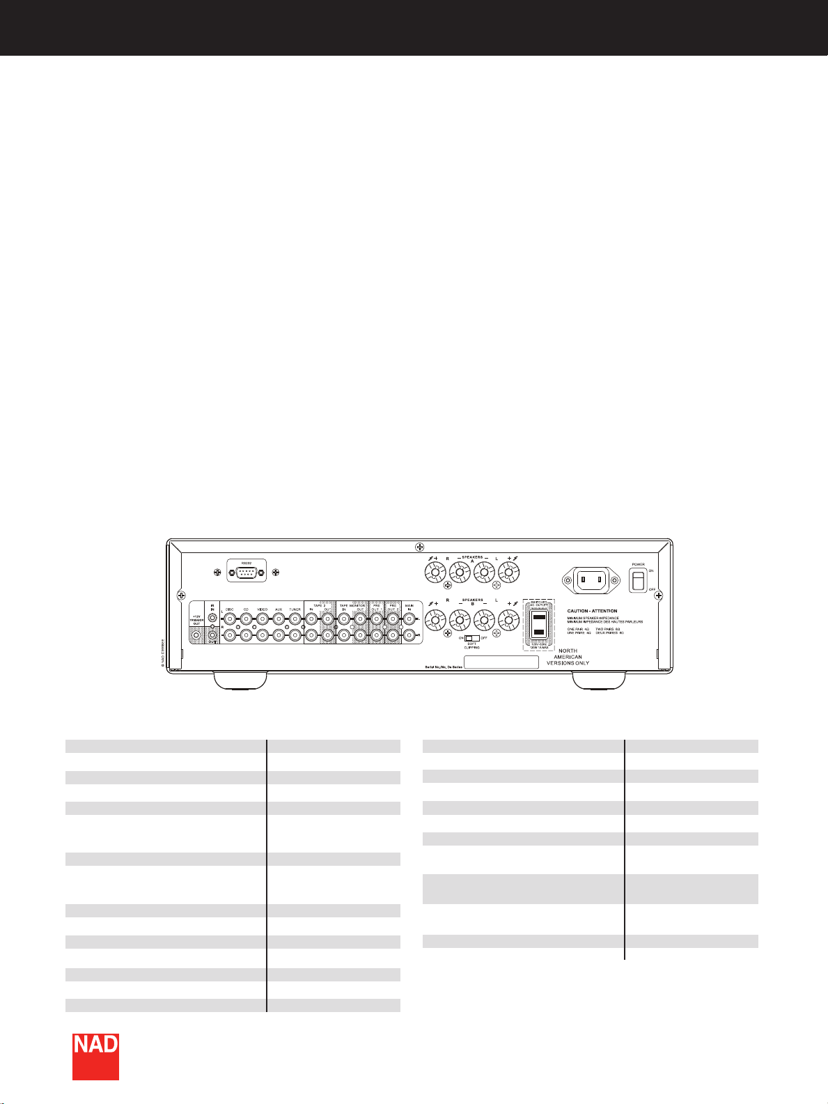
Flexibility is another NAD strong point. The C355BEE has 7 line inputs (including 2 tape in/outputs with
dubbing facility) and the pre-amplifier section can be separated from the power amplifier for easy upgrades
or adding ancillary equipment. Thus the C355BEE can be expanded to meet future system needs. The
C355BEE sports 2 pre-amp outputs: Many systems benefit from the use of multiple power amplifiers for
“Bi-Amping” (using separate power amplifiers to drive the bass and treble section of a loudspeaker). With
the second Preout 2 facility an extra power amplifier, such as NAD’s C272, which has identical amplification
factor (gain) as the C355BEE’s power amp section - is easily connected. This output can also be used to
connect a powered subwoofer, an increasingly popular option.
For remote on/off switching of ancillary components in a system, such as power amplifiers or active
speakers, the C355BEE is equipped with a 12V-trigger system. When switching the amplifier on, the 12Vtrigger output is also activated which in turn can activate a 12V-trigger input and switch on the remote
devices. Besides the 12V-trigger, the C355BEE also has rear panel IR in and out and an RS-232 port to
allow interface to advanced home automation systems. In fact, NAD is a ‘certified partner’ with AMX and
Crestron, leaders in the field of home automation guaranteeing compatibility with these systems.
Page 6
It is fashionable to omit tone controls nowadays: However,
provided that the tone controls are properly designed, they can
be really useful tools in making improvements to the overall
sound. The C355BEE tone controls only work at the frequency
extremes leaving the critical mid-band essentially unaltered. The
tone control circuits can be completely bypassed by using the tone
defeat switch. The C355BEE also incorporates NAD’s acclaimed
switchable “Soft Clipping” circuit, which significantly reduces the
risk of damage to loudspeakers due to prolonged high power
operation.
Design: PowerDrive™
The C355BEE also benefits from NAD’s proprietary PowerDrive
circuit topology, now well established and used throughout
the NAD product range. The PowerDrive topology allows the
C355BEE to deliver maximum performance under virtually any
circumstance, independent of the loudspeakers it is driving. The
circuitry automatically senses the impedance characteristics of
the loudspeaker and will then adjust its power supply settings
to best cope with that specific load. PowerDrive topology is a
practical approach for enabling an amplifier to easily deal with
musical dynamics and difficult speaker loads. Thus we have the
highly desirable characteristics of high dynamic power and low
impedance drive capability in one affordable package.
NAD also takes a stand against the meaningless “brochure power”
touted by many of our competitors by offering Full Disclosure
power specs. We specify minimum continuous power, across the
entire audible range of frequencies, at rated distortion, for both
8 and 4 Ohms with all channels driven simultaneously. Perhaps
even more importantly, we also specify Dynamic Power at 8, 4,
and even 2 Ohms, which better describes the way the amplifier
will perform in the real world, with musical signals and reactive
loudspeaker loads.
Less Distortion = More Music
Noise and distortion mask the fine details of a musical recording
robbing musical texture and dimension and replacing them with
non-musical artifacts. NAD has spent the last 35 years perfecting
our designs to have the lowest distortion and highest power in its
price class. This cannot be overstated! Our competitors often rate
distortion at only 80% of rated power, and even then can’t match
our very conservative spec of 0.03% at any frequency within the
range of human hearing. At 80% power our distortion drops to
0.005% or less. Our noise spec is often 10dB (100 times!) less
than that of competing amplifiers. This is far from trivial.
However, even the most carefully reported specs cannot fully
describe the sonic performance of an amplifier. Only your own
ears can finally judge our achievement. We urge you to listen
and compare NAD to other products in its price range, and even
higher. We don’t think you’ll find anything that comes close to
offering the C355BEE’s overall musical satisfaction, well-rounded
performance, and stellar value for money.
SPECIFICATIONS
Pre-Amp Section
Line level inputs
Input impedance (R+C)
Input sensitivity, rated power
Signal/noise ratio
Signal/noise ratio preamp out
Frequency response (20Hz - 20kHz)*
Line level outputs
Output impedance
Tape
Power Amp Section
Continuous output power into 8Ω
Rated Distortion (THD 20Hz - 20kHz)
Clipping power
IHF dynamic power at 8Ω
IHF dynamic power at 4Ω
IHF dynamic power at 2Ω
Damping factor (ref. 8Ω, 50Hz)
NADElectronicsInternationalreservestherighttochangespecicationsorfeatureswithoutnotice.NADisaregisteredtrademarkofNADElectronics
International.Allrightsreserved.Nopartofthispublicationmaybereproduced,stored,ortransmittedinanyformwhatsoeverwithoutthewritten
Input impedance
220kΩ / 100pF
300mV
98.0dB ref. 1W
110dB ref. 500mV
±0.3dB
80Ω
Source Z + 1kΩ
80W (19.5dBW)
0.02%
92W
140W (21.5dBW)
220W (23.4dBW)
270W (24.3dBW)
>160
permissionofNADElectronicsInternational.©12/07NADElectronicsInternational.
Input Sensitivity (for rated power into 8Ω)
Voltage gain
Frequency response; 20Hz-20kHz
Signal/noise ratio; ref 1W
Signal/noise ratio; ref rated power
Phones
Physical Specifications
Net Dimensions (W x H x D)
Gross Dimensions (W x H x D)**
Net Weight
Shipping Weight
* Tone Defeat on
** Gross Dimensions include volume knob / speaker terminals / connectors / feet.
Note: Installers should allow a minimum clearance of 2 - 4 inches for wire management.
www.NADelectronics.com
20kΩ/ 1nF
940mV
29dB
+/-0.1dB
105dB
124dB
68Ω
17 1/8 x 4 1/2 x 11 7/16”
(435 x 116 x 292mm)
17 1/8 x 5 x 13 1/8”
(435 x 130 x 338mm)
18.75 lbs (8.5kg)
23 lbs (10.4kg)
Page 7

Page 8

Page 9

®
C 355BEE
Integrated Amplier
ENGLISHFRANÇAISESPAÑOLITALIANODEUTSCHNEDERLANDSSVENSKAРУССКИЙ
Owner’s Manual
Manuel d’Installation
Manual del Usuario
Manuale delle Istruzioni
Bedienungsanleitung
Gebruikershandleiding
Bruksanvisning
Инструкция по эксплуатации
Page 10

IMPORTANT SAFETY INSTRUCTIONS
2
ENGLISH FRANÇAIS ESPAÑOL ITALIANO DEUTSCH NEDERLANDS SVENSKA РУССКИЙ
1. Read instructions - All the safety and operating instructions should
be read before the product is operated.
2. Retain instructions - The safety and operating instructions should be
retained for future reference.
3. Heed Warnings - All warnings on the product and in the operating
instructions should be adhered to.
4. Follow Instructions - All operating and use instructions should be
followed.
5. Cleaning - Unplug this product from the wall outlet before cleaning.
Do not use liquid cleaners or aerosol cleaners. Use a damp cloth for
cleaning.
6. Attachments - Do not use attachments not recommended by the
product manufacturer as they may cause hazards.
7. Water and Moisture - Do not use this product near water-for
example, near a bath tub, wash bowl, kitchen sink, or laundry tub; in a
wet basement; or near a swimming pool; and the like.
8. Accessories - Do not place this product on an unstable cart, stand,
tripod, bracket, or table. The product may fall, causing serious injury
to a child or adult and serious damage to the product. Use only with a
cart, stand, tripod, bracket, or table recommended by the manufacturer,
or sold with the product. Any mounting of the product should follow
the manufacturer’s instructions, and should use a mounting accessory
recommended by the manufacturer.
9. Cart - A product and cart combination should be moved
with care. Quick stops, excessive force, and uneven surfaces
may cause the product and cart combination to overturn.
10. Ventilation - Slots and openings in the cabinet are provided for
ventilation to ensure reliable operation of the product and to protect it
from overheating. These openings must not be blocked or covered. The
openings should never be blocked by placing the product on a bed,
sofa, rug, or other similar surface. This product should not be placed in a
built-in installation such as a bookcase or rack unless proper ventilation
is provided or the manufacturer’s instructions have been adhered to.
11. Power Sources - This product should be operated only from the type
of power source indicated on the marking label and connected to a
MAINS socket outlet. If you are not sure of the type of power supply to
your home, consult your product dealer or local power company.
12. Power-Cord Protection - Power-supply cords should be routed so
that they are not likely to be walked on or pinched by items placed
upon or against them, paying particular attention to cords at plugs,
convenience receptacles, and the point where they exit from the
product.
13. Mains Plug - Where the mains plug or an appliance coupler is used
as the disconnect device, the disconnect device shall remain readily
operable.
14. Outdoor Antenna Grounding - If an outside antenna or cable system
is connected to the product, be sure the antenna or cable system is
grounded so as to provide some protection against voltage surges
and built-up static charges. Article 810 of the National Electrical Code,
ANSI/NFPA 70, provides information with regard to proper grounding
of the mast and supporting structure, grounding of the lead-in wire
to an antenna discharge unit, size of grounding conductors, location
of antenna discharge unit, connection to grounding electrodes, and
requirements for the grounding electrode.
NOTE TO CATV SYSTEM INSTALLER
This reminder is provided to call the CATV system installer’s attention to Section 820-40
of the NEC which provides guidelines for proper grounding and, in particular, specifies
that the cable ground shall be connected to the grounding system of the building, as
close to the point of cable entry as practical.
15. Lightning - For added protection for this product during a lightning
storm, or when it is left unattended and unused for long periods of
time, unplug it from the wall outlet and disconnect the antenna or
cable system. This will prevent damage to the product due to lightning
and power-line surges.
16. Power Lines - An outside antenna system should not be located in the
vicinity of overhead power lines or other electric light or power circuits,
or where it can fall into such power lines or circuits. When installing an
outside antenna system, extreme care should be taken to keep from
touching such power lines or circuits as contact with them might be
fatal.
17. Overloading - Do not overload wall outlets, extension cords, or
integral convenience receptacles as this can result in a risk of re or
electric shock.
18. Flame Sources - No naked ame sources, such as lighted candles,
should be placed on the product.
19. Object and Liquid Entry - Never push objects of any kind into this
product through openings as they may touch dangerous voltage
points or short-out parts that could result in a re or electric shock.
Never spill liquid of any kind on the product.
20. Headphones - Excessive sound pressure form earphones and
headphones can cause hearing loss.
21. Damage Requiring Service - Unplug this product from the wall
outlet and refer servicing to qualied service personnel under the
following conditions:
a. When the power-supply cord or plug is damaged.
b. If liquid has been spilled, or objects have fallen into the product.
c. If the product has been exposed to rain or water.
d. If the product does not operate normally by following the
operating instructions. Adjust only those controls that are covered
by the operating instructions as an improper adjustment of other
controls may result in damage and will often require extensive
work by a qualied technician to restore the product to its normal
operation.
e. If the product has been dropped or damaged in any way.
f. When the product exhibits a distinct change in performance-this
indicates a need for service.
22. Replacement Parts - When replacement parts are required, be sure
the service technician has used replacement parts specied by the
manufacturer or have the same characteristics as the original part.
Unauthorized substitutions may result in re, electric shock, or other
hazards.
Page 11

IMPORTANT SAFETY INSTRUCTIONS
23. Battery Disposal - When disposing of used batteries, please comply
with governmental regulations or environmental public instruction’s
rules that apply in your country or area. Batteries (battery pack or
batteries installed) must not be exposed to excessive heat such as
sunshine, re or the like.
24. Safety Check - Upon completion of any service or repairs to this
product, ask the service technician to perform safety checks to
determine that the product is in proper operating condition.
25. Wall or Ceiling Mounting - The product should be mounted to a wall
or ceiling only as recommended by the manufacturer.
WARNING
The lightning ash with arrowhead symbol, within an equilateral
triangle, is intended to alert the user to the presence of
uninsulated “dangerous voltage” within the product’s enclosure
that may be of sucient magnitude to constitute a risk of
electric shock to persons
The exclamation point within an equilateral triangle is intended
to alert the user to the presence of important operating
and maintenance (servicing) instructions in the literature
accompanying the appliance.
IMPORTANT
DO NOT make any connection to the larger terminal which is marked
with the letter ‘E’ or by the safety earth symbol or colored GREEN or GREEN
AND YELLOW. The wires in the mains lead on this product are colored in
accordance with the following code:
BLUE - NEUTRAL
BROWN - LIVE
As these colors may not correspond with the colored markings identifying
the terminals in your plug, proceed as follows:
• The BLUE wire must be connected to the terminal marked with the
letter ‘N’ or colored BLACK.
• The BROWN wire must be connected to the terminal marked with the
letter ‘L’ or colored RED
• When replacing the fuse, only a correctly rated and approved type
should be used, and be sure to re-t the fuse cover.
IF IN DOUBT CONSULT A COMPETENT ELECTRICIAN.
This product is manufactured to comply with the radio
interference requirements of EEC DIRECTIVE 2004/108/EC.
NOTES ON ENVIRONMENTAL PROTECTION
At the end of its useful life, this product must not be disposed
of with regular household waste but must be returned to a
collection point for the recycling of electrical and electronic
equipment. The symbol on the product, user’s manual and
packaging point this out.
ENGLISHFRANÇAISESPAÑOLITALIANODEUTSCHNEDERLANDSSVENSKAРУССКИЙ
WARNING: TO REDUCE THE RISK OF FIRE OR ELECTRIC SHOCK,
DO NOT EXPOSE THIS APPARATUS TO RAIN OR MOISTURE AND
OBJECTS FILLED WITH LIQUIDS, SUCH AS VASES, SHOULD NOT BE
PLACED ON THIS APPARATUS.
CAUTION REGARDING PLACEMENT
To maintain proper ventilation, be sure to leave a space around the unit
(from the largest outer dimensions including projections) than is equal to,
or greater than shown below.
Left and Right Panels: 10 cm
Rear Panel: 10 cm
Top Panel: 50 cm
IMPORTANT INFORMATION TO UK CUSTOMERS
DO NOT cut o the mains plug from this equipment. If the plug tted is
not suitable for the power points in your home or the cable is too short
to reach a power point, then obtain an appropriate safety approved
extension lead or consult your dealer. If nonetheless, the mains plug is
cut o, REMOVE THE FUSE and dispose of the PLUG immediately, to avoid
possible shock hazard by inadvertent connection to the mains supply. If
this product is not provided with a mains plug, or one has to be tted, then
follow the instructions given below:
The materials can be reused in accordance with their markings. Through
re-use, recycling of raw materials, or other forms of recycling of old
products, you are making an important contribution to the protection of
our environment.
Your local administrative oce can advise you of the responsible waste
disposal point.
RECORD YOUR MODEL NUMBER NOW, WHILE YOU CAN SEE IT
The model and serial number of your new C 355BEE are located on the
back of the cabinet. For your future convenience, we suggest that you
record these numbers here:
Model number : . . . . . . . . . . . . . . . . . . . . . . . . . . . . . . . . . . . . . .
Serial number : . . . . . . . . . . . . . . . . . . . . . . . . . . . . . . . . . . . . . .
NAD is a trademark of NAD Electronics International, a division of Lenbrook Industries Limited
Copyright 2008, NAD Electronics International, a division of Lenbrook Industries Limited
3
Page 12

INTRODUCTION
4
ENGLISH FRANÇAIS ESPAÑOL ITALIANO DEUTSCH NEDERLANDS SVENSKA РУССКИЙ
GETTING STARTED
UNPACKING AND SETUP
WHAT’S IN THE BOX
Packed with your C 355BEE you will nd:
• The SR 6 remote control with 2 (two) AAA batteries
• This owner’s manual
SAVE THE PACKAGING
Please save the box and all of the packaging in which your C 355BEE
arrived. Should you move or otherwise need to transport your receiver,
this is by far the safest container in which to do so. We’ve seen too many
otherwise perfect components damaged in transit for lack of a proper
shipping carton, so please: Save that box!
CHOOSING A LOCATION
Choose a location that is well ventilated (with at least several inches to
both sides and behind), and that will provide a clear line of sight, within
25 feet/8 meters, between the C 355BEE’s front panel and your primary
listening/viewing position. This will ensure reliable infrared remote control
communications. The C 355BEE generates a modest amount of heat, but
nothing that should trouble adjacent components. It is perfectly possible to
stack the C 355BEE on top of other components.
NOTES ON INSTALLATION
Your NAD C 355BEE should be placed on a rm, level surface. Avoid
placing the unit in direct sunlight or near sources of heat and damp. Allow
adequate ventilation. Do not place the unit on a soft surface like a carpet.
Do not place it in an enclosed position such a bookcase or cabinet that
may impede the air-ow through the ventilation slots. Make sure the unit is
switched o before making any connections.
The RCA sockets on your NAD C 355BEE are colour coded for convenience.
Red and white are Right and Left audio respectively.
Use high quality leads and sockets for optimum performance and reliability.
Ensure that leads and sockets are not damaged in any way and all sockets
are rmly pushed home.
For best performance, use quality speaker leads of 16 gauge (1.5mm)
thickness or more. If the unit is not going to be used for some time,
disconnect the plug from the AC socket.
Should water get into your NAD C 355BEE, shut o the power to the unit
and remove the plug from the AC socket. Have the unit inspected by a
qualied service technician before attempting to use it again.
BARE WIRES AND PIN CONNECTORS
WARNING: The terminals marked with this symbol
are hazardous live. External wiring connected to these
terminals requires installation by an instructed person or
the use of ready-made leads or cords.
Bare wires and pin sockets should be inserted into the hole in the shaft
of the terminal. Unscrew the speaker terminal’s plastic bushing until the
hole in the screw shaft is revealed. Insert the pin or bare cable end into
the hole and secure the cable by tightening down the terminal’s bushing.
Ensure bare wire from the speaker cables does not touch the back panel or
another socket. Ensure that there is only 1/2” (1cm) of bare cable or pin and
no loose strands of speakers wire.
QUICK START
In case you simply cannot wait to experience the performance of your new
NAD C 355BEE, we provide the following “Quick Start” instructions to get
you underway.
Please make all the connections to your C 355BEE with the unit unplugged.
It is also advisable to power-down or unplug all associated components
while making or breaking any signal or AC power connections.
1 Connect the speakers to the rear Speaker terminals and sources to the
relevant rear input sockets.
2 Plug in the AC power cord.
3 Switch the POWER button on the rear panel to ON in order to turn the
C 355BEE to standby.
4 Press the front panel Standby button to turn the C 355BEE ON.
5 Press the required input selector.
DO NOT REMOVE THE COVER, THERE ARE NO USERSERVICEABLE
PARTS INSIDE.
Use a dry soft cloth to clean the unit. If necessary, lightly dampen the cloth
with soapy water. Do not use solutions containing benzol or other volatile
agents.
Page 13

IDENTIFICATION OF CONTROLS
FRONT PANEL
1 2
6 7 8 9 10 11
1 STANDBY BUTTON: The Standby Button turns ON and set to standby
the C 355BEE. This button will only function when the Power/Standby/
Protection LED is either amber representing the standby state, or green
representing the ON state.
2 POWER/STANDBY/PROTECTION LED: Upon switching the power
ON, the LED will light up red for a few seconds before the protection
circuit is deactivated. The LED will then turn green, representing normal
operation.
In cases of serious abuse of the amplier, such as overheating,
excessively low loudspeaker impedance, short circuit etc. the amplier
will engage its Protection circuitry, indicated by the LED turning from
green to red, and the sound being muted.
In such a case, turn the amplier o by the rear panel POWER button,
wait for it to cool down and/or check the speaker connections,
making sure the overall loudspeaker impedance doesn’t go below 4
ohms. Once the cause for the protection circuitry to engage has been
removed, switch ON the rear POWER button and the Standby Button to
resume normal operation.
3 4 5
4 SOFT CLIPPING INDICATOR: The green Soft Clipping LED shows that
the Soft Clipping mode is engaged. Refer also to “IDENTIFICATION OF
CONTROLS - REAR PANEL, item 14 Soft Clipping” for more information.
5 TONE DEFEAT: The TONE DEFEAT switch bypasses the tone control
section of the NAD C 355BEE. If the Tone Controls are not normally
used and left in the 12 o’clock position, then it is advisable to switch
out the Tone Control section altogether by using this switch. In the ‘out’
position, the Tone Control circuits are active; pushing the TONE DEFEAT
switch ‘in’ bypasses the Tone Control section.
6 HEADPHONE SOCKET: A 1/4” stereo jack socket is supplied for
headphone listening and will work with conventional headphones
of any impedance. The headphone socket will work in parallel to the
selected speakers. To listen to headphones only, de-select Speakers
A and/or B. The volume, tone and balance controls are operative for
headphone listening. Use a suitable adapter to connect headphones
with other types of sockets, such as 3.5mm stereo ‘personal stereo’ jack
plugs.
ENGLISHFRANÇAISESPAÑOLITALIANODEUTSCHNEDERLANDSSVENSKAРУССКИЙ
3 INFRA-RED REMOTE CONTROL COMMAND RECEIVER: The infrared
sensor, located behind this circular window, receives commands from
the remote control. There must be a clear line-of-sight path from the
remote control to this window; if that path is obstructed, the remote
control may not work.
NOTE
Direct sunlight or very bright ambient lighting may aect the operating
range and angle for the remote control handset.
WARNING
Make certain that the volume control is turned to minimum (fully
counter-clockwise) before connecting or disconnecting headphones.
Listening at high levels can damage your hearing.
7 A SPEAKERS B: The Speakers A and B buttons engage or disengage
the speakers connected respectively to the Speakers A and Speakers B
terminals on the rear panel. Press “A” to switch ON or OFF the speakers
connected to the speaker A terminals. Press B to switch ON or OFF the
speakers connected to the speaker B terminals. The indicator directly
over the buttons shows the status of Speakers A and B.
5
Page 14

IDENTIFICATION OF CONTROLS
6
ENGLISH FRANÇAIS ESPAÑOL ITALIANO DEUTSCH NEDERLANDS SVENSKA РУССКИЙ
FRONT PANEL
8 INPUT SELECTORS: These buttons select the active input to the NAD
C 355BEE and the signal sent to the loudspeakers, the Tape outputs
and the PRE OUT sockets. The buttons on the remote control handset
duplicate these buttons. Green LEDs just above each button will
indicate which input is currently selected.
DISC/MP (Media Player) : Selects a line-level source connected to the
DISC sockets as the active input. When a 3.5mm stereo plug is inserted
into the MP socket, the indicator above the socket will illuminate, and
the DISC line-level source will be disconnected. It is recommended
to mute the volume or switch to a dierent input before plugging/
unplugging the external Media Player cable.
CD : Selects the CD (or other line-level source) connected to the CD
sockets as the active input.
VIDEO : Selects the VCR (or stereo TV/Satellite/Cable receiver)
connected to the VIDEO sockets as the active input.
AUX : Selects a line-level source connected to the AUX sockets as the
active input.
TUNER : Selects the tuner (or other line-level source) connected to the
tuner sockets as the active input.
TAPE 2 : Selects Tape 2 as the active input.
TAPE MONITOR : Selects the output from a tape recorder when
playing back tapes or monitoring recordings being made through the
Tape Monitor sockets. Press the Tape Monitor button once to select it
and again to return to the normal input selection.
TAPE MONITOR does not override the current input selection. For
example, if CD is the active input when TAPE Monitor is selected, then
the CD signal will continue to be selected and sent to both the TAPE 2
and TAPE MONITOR OUTPUT sockets, but it is the sound from recorder
connected to Tape Monitor that will be heard on the loudspeakers.
Apart from the amber LED to indicate Tape Monitor is engaged, the
green LED for the active input will also stay lit.
9 TONE CONTROLS: The NAD C 355BEE is tted with BASS and TREBLE
tone controls to adjust the tonal balance of your system. The 12 o’clock
position is ‘at’ with no boost or cut, and an indent indicates this
position. Rotate the control clockwise to increase the amount of Bass
or Treble. Rotate the control anti-clockwise to decrease the amount of
Bass or Treble. The Tone controls do not aect recordings made using
the Tape outputs but will aect the signal going to the Pre-amp output
(PRE OUT 1 or PRE OUT 2).
10 BALANCE: The BALANCE control adjusts the relative levels of the left
and right speakers. The 12 o’clock position provides equal level to the left
and right channels. A detent indicates this position. Rotating the control
clockwise moves the balance towards the right. Rotating the control anticlockwise moves the balance to the left. The BALANCE control does not
aect recordings made using the Tape outputs but will aect the signal
going to the Pre-amp output (PRE OUT 1 or PRE OUT 2).
11 VOLUME: The VOLUME control adjusts the overall loudness of the
signals being fed to the loudspeakers. It is motor driven and can be
adjusted from the remote control handset. The VOLUME control does
not aect recordings made using the Tape outputs but will aect the
signal going to the Pre-amp output (PRE OUT 1 or PRE OUT 2).
On the remote control handset, press the MUTE button to temporarily
switch OFF the sound to the speakers and headphones. Mute mode
is indicated by the Power/Standby/Protection LED ashing. Press the
MUTE button again to restore sound. Mute does not aect recordings
made using the Tape outputs but will aect the signal going to the Preamp output (PRE OUT 1 or PRE OUT 2).
NOTE
The remote control handset with the C 355BEE supplied is of a universal
NAD type, designed to operate several NAD models. Some buttons on
this handset are inoperative as the functions aren’t supported by the
C 355BEE. The Video 2 and Video 3 input selector buttons on the remote
control handset are inoperative in the case of the C 355BEE.
Page 15

IDENTIFICATION OF CONTROLS
REAR PANEL
1 2 3 4 5 6 187 8 9 10 11 12 13 14 15 16 17
ATTENTION!
Please make sure that the C 355BEE is powered OFF or unplugged before making any connections. It is also advisable to power-down or unplug all
associated components while making or breaking any signal or AC power connections.
ENGLISHFRANÇAISESPAÑOLITALIANODEUTSCHNEDERLANDSSVENSKAРУССКИЙ
1 RS-232: Connect this interface via RS-232 serial cable (not supplied) to
any Windows® compatible PC to allow remote control of the C 355BEE
through NAD’s proprietary PC software or other compatible external
controllers. NAD is a certied partner of AMX and Crestron and fully
supports these external devices. See your NAD audio specialist for more
information.
2 12V TRIGGER OUTPUT: The 12V TRIGGER OUTPUT is used for
controlling external equipment that is equipped with a 12V trigger
input. This output will be 12V when the C 355BEE is ON and 0V when
the unit is either OFF or in standby. This output can drive a load up to
50mA at 12V.
3 IR IN/OUT: These mini-jacks accept and output remote-controlled
codes in electrical format, using industry-standard protocols, for use
with “IR-repeater” and multi-room systems and related technologies.
IR IN : This input is connected to the output of an IR (infrared) repeater
(Xantech or similar) or the IR output of another component to allow
control of the C 355BEE from a remote location.
IR OUT : When connected to the IR IN of an ancillary equipment, direct
the ancillary equipment’s own remote control to the C 355BEE’s infrared
receiver to command or control the linked unit.
All NAD products with IR IN/IR OUT features are fully compatible with
the C 355BEE. For non-NAD models, please check with your other
product’s service specialists as to their compatibility to the C 355BEE’s IR
features.
4 DISC INPUT: Input for additional line level input signals such as CD,
Mini Disc player or the output signal from a step-up amplier for a
turntable. Use a twin RCA-to-RCA lead to connect the auxiliary unit’s
left and right ‘Audio Outputs’ to this input.
NOTE
When a 3.5mm stereo plug is inserted into the Front Panel MP socket,
the indicator above the socket will illuminate, and the DISC line-level
source will be disconnected. It is recommended to mute the volume or
switch to a dierent input before plugging/unplugging the external
Media Player cable.
5 CD INPUT: Input for a CD or other line-level signal source. Use a
twin RCA-to-RCA lead to connect the CD player’s left and right ‘Audio
Outputs’ to this input. The NAD C 355BEE only accepts analogue signals
from your CD player.
6 VIDEO INPUT: Input for the audio signal from a stereo VCR (or stereo
TV/Satellite/Cable receiver) or other line-level audio source. Using twin
RCA-to-RCA leads, connect to the left and right ‘Audio Outputs’ of the
unit to these inputs.
NOTE
These are audio inputs only.
7 AUX INPUT: Input for additional line level input signals such as
another CD player. Use a twin RCA-to-RCA lead to connect the auxiliary
unit’s left and right ‘Audio Outputs’ to this input.
8 TUNER INPUT: Input for a tuner or other line-level signal source.
Use a twin RCA-to-RCA lead to connect the tuner left and right ‘Audio
Outputs’ to this input.
7
Page 16

IDENTIFICATION OF CONTROLS
8
ENGLISH FRANÇAIS ESPAÑOL ITALIANO DEUTSCH NEDERLANDS SVENSKA РУССКИЙ
REAR PANEL
9 TAPE 2 IN/OUT: Connections for analogue recording and playback
to an audio tape recorder of any type. Using twin RCA-to-RCA leads,
connect to the left and right ‘Audio Output’ of the tape machine to the
TAPE 2 IN sockets for playback and tape monitoring. Connect the left
and right ‘Audio Input’ of the tape machine to the TAPE 2 OUT sockets
for recording.
10 TAPE MONITOR IN/OUT: Connections for analogue recording and
playback to a secondary audio tape recorder of any type. Using twin
RCA-to-RCA leads, connect to the left and right ‘Audio Output’ of the
tape machine to the TAPE MONITOR IN sockets for playback and tape
monitoring. Connect the left and right ‘Audio Input’ of the tape machine
to the TAPE MONITOR OUT sockets for recording.
TO MAKE A RECORDING
When any source is selected, its signal is also fed directly to any tape
machine connected to the TAPE 2 OUT or TAPE MONITOR OUT for
recording.
TAPE TO TAPE COPYING
You can copy between two tape machines connected to your NAD
C 355BEE. Put the source tape in the recorder connected to Tape 2 and the
blank tape into the recorder connected to Tape Monitor. By selecting TAPE
2 input you can now record from Tape 2 to Tape Monitor and monitor the
signal coming from the original tape.
NOTE
There will be no Tape 2 output when Tape 2 (or Tape Monitor OUT when
Tape Monitor) is the selected source input. This prevents feedback
through the recording component thereby preventing possible damage
to your speakers.
11 PRE OUT 1: The PRE OUT 1 sockets can be used to drive an additional
power amplier. Use a twin RCA-to-RCA lead to connect to the left and
right ‘Audio Input’ of the Power amplier or processor to the PRE OUT 1
sockets.
12 PRE OUT 2: Connections to an external power amplier or processor,
such as a surround-sound decoder. In normal use, these should be
connected to the Main-In sockets (No. 13) with the links supplied. To
connect your NAD C 355BEE to external processor or amplier sections,
remove rst these links. Use a twin RCA-to-RCA lead to connect to the
left and right ‘Audio Input’ of the Power amp or processor to the PRE
OUT 2 sockets.
NOTE
Always turn the C 355BEE and associated external power ampliers OFF
before connecting or disconnecting anything to the PRE OUT 1, 2 and
MAIN IN sockets. The PRE OUT 1 and 2 output signals will be aected by
the C 355BEE’s volume and tone control settings.
14 SOFT CLIPPING™: When an amplier is driven beyond its specied
power output, a hard, distorted sound can be heard on very loud
sounds. This is caused by the amplier cutting o or ‘hard clipping’ the
peaks of sound that was not designed to reproduce. The NAD Soft
Clipping circuit gently limits the output of the system to minimise
audible distortion if the amplier is overdriven. If your listening involves
moderate power levels you may leave the Soft Clipping switch to OFF.
If you are likely to play at high levels, that could stretch the amplier’s
power capability, then switch Soft Clipping ON. The Soft Clipping™ LED
on the front panel will illuminate when the amplier is in Soft Clipping
mode.
15 SPEAKERS A, B: The C 355BEE is equipped with two sets of speaker
connectors. Use the Speakers A connectors for the ‘main’ speakers and
use the Speakers B connectors for a second pair, for example, extension
speakers located in another room.
Connect the right speaker to the terminals marked ‘R +’ and ‘R-’ ensuring
that the ‘R+’ is connected to the ‘+’ terminal on your loudspeaker and
the ‘R-’ is connected to the loudspeaker’s ‘-’ terminal. Connect the
terminals marked ‘L+’ and ‘L-’ to the left speaker in the same way.
Always use heavy duty (16 gauge; 1.5mm, or thicker) stranded wire to
connect loudspeakers to your NAD C 355BEE. The high-current binding
post terminals can be used as a screw terminal for cables terminating in
spade or pin sockets or for cables with bare wire ends.
16 SWITCHED AC OUTLET (North America version only): The
SWITCHED AC OUTLET can supply switched power to another
component or accessory. This convenience outlet can be switched
ON or OFF using only the POWER switch located at the rear panel. The
SWITCHED AC OUTLET cannot be switched ON or OFF using the front
panel Standby button or the ON/OFF button of the remote control. The
total draw of all devices connected to this Switched AC outlet must not
exceed 120 watts.
17 IEC AC MAINS (POWER) INPUT: The C 355BEE comes supplied with
a separate AC Mains cable. Before connecting the cable to a live wall
socket ensure that it is rmly connected to the NAD C 355BEE’s AC
Mains input socket rst. Always disconnect the AC Mains cable plug
from the live wall socket rst, before disconnecting the cable from the
C 355BEE Mains input socket.
18 POWER SWITCH: The POWER switch supplies the master AC mains
power for the C 355BEE. When the switch is in the ON position the
C 355BEE is in standby as shown by the amber Status Condition LED,
above the Standby button on the front panel. If you intend not to use the
amplier for long periods of time, switch the POWER switch to the OFF
position.
13 MAIN IN: Connections to an external pre-amplier or processor, such as
a surround-sound decoder. In normal use, these should be connected
to PRE OUT 2 sockets (No. 12) with the links supplied. To connect your
NAD C 355BEE to external processor or pre-amplier rst remove these
links. Use a twin RCA-to-RCA lead to connect to the left and right ‘Audio
Output’ of the pre-amp or processor to the Main-In sockets.
NOTE
Always turn the amplier o before connecting or disconnecting
anything from to PRE OUT 1, 2 and MAIN IN sockets.
Page 17

IDENTIFICATION OF CONTROLS
SR 6 REMOTE CONTROL
1
ENGLISHFRANÇAISESPAÑOLITALIANODEUTSCHNEDERLANDSSVENSKAРУССКИЙ
2
3
11
10
7
8
9
12
5
6
6
6
6
6
4
5
6
6
5
Press in and lift tab to remove battery cover out
of recess.
Place batteries into opening. Ensure the correct
tting is observed.
Replace battery cover by aligning and inserting
the two tabs into the holes. Press battery cover
into place until ‘clicks’ closed.
9
Page 18

IDENTIFICATION OF CONTROLS
10
ENGLISH FRANÇAIS ESPAÑOL ITALIANO DEUTSCH NEDERLANDS SVENSKA РУССКИЙ
SR 6 REMOTE CONTROL
The SR 6 remote control handset handles the key functions of the
C 355BEE as well as other NAD Stereo Receivers, Integrated Ampliers
and Preampliers. It has additional controls to remotely operate NAD CD
Players, FM/AM Tuners and dedicated FM/AM/DAB Tuners. It will operate
up to a distance of 16ft (5m). Alkaline batteries are recommended for
maximum operating life. Two AAA (R 03) batteries should be tted in the
battery compartment at the rear of the Remote Control handset. When
replacing batteries, check that they have been put in the right way round,
as indicated on the base of the battery compartment.
When a command from the remote control is received, the Standby/
protection indicator will blink. Note that the indicator may also blink
when receiving commands not necessarily for the C 355BEE but for other
components in the system. Please refer to previous sections of the manual
for a full description of individual functions.
1 POWER ON & OFF: The SR 6 remote has a separate ON and OFF
button. This can be particularly useful to keep components within a
system “in sync”: This way all components will switch to standby when
OFF is pressed or switched to operating mode when ON is pressed
- instead of some components switching ON when the C 355BEE is
switched to Standby. (Note that the other components have to be
capable of responding to the separate ON and OFF commands as well).
Press the ON button to switch the unit from Standby to operating
mode; The Power/Standby/Protection LED indicator will turn from
amber, to red, then to green and the indicator for the last selected
input will blink and light up. Press the OFF button to switch the unit to
Standby mode: The Power/Standby/Protection LED indicator will light
up amber.
2 INPUTS: The input selector buttons perform the same functions as the
buttons labeled the same on the front panel.
3 NUMERIC KEYS: The numeric keys allow for direct input of tracks for
CD players, and direct channel/preset access for tuners and receivers.
4 DIMMER: Press this button to dim the front panel display. Depending
on the NAD model, the brightness of the front panel display will vary
when you toggle this button.
5 CD PLAYER CONTROL (for use with NAD CD Player)
engages Pause
engages Stop
engages Play
/ engages reverse or forward Scan
/ engages reverse of forward Skip
engages CD drawer Open/Close; Press once to open the CD drawer
then once again to close the CD drawer
RPT. This button engages the Repeat Play mode for disc playback.
Toggle to repeat one track, repeat all tracks or turn o repeat play
mode.
AUTO TUNE: In DAB mode, press this button to automatically scan all
available local stations.
FM MUTE: In DAB mode, pressing this button will activate Dynamic
Range Control, preset tune, manual tune, station order or other
appropriate features. In FM mode, press this button to select the stereo
or mono mode for FM tuning.
BLEND: The Blend button toggles between engaging and disengaging
the Blend feature. The NAD Blend feature will allow you to reduce the
amount of noise and hiss normally associated with received weak radio
stations but still retain some level of stereo separation, instead of mono.
AM/FM/DAB: In tuner mode, toggle this button to switch to DAB, FM
and AM frequency bands.
7 SLEEP: Press SLEEP to switch o the applicable tuner after a preset
number of minutes. Each consecutive press will reduce the sleep time
in preset increments until sleep mode is cancelled as could be shown in
the front panel display.
8 TUNER/CD: The TUNER/CD switch applies relevant tuner controls
when in the TUNER position, and applies CD controls to the appropriate
buttons when in the CD position.
9 VOLUME: Press VOLUME or buttons to respectively increase or
decrease the loudness level. Release the button when the desired
level is reached. The motorised Volume control on the front panel will
indicate the level set. The Volume buttons do not aect recordings
made using the Tape outputs but will aect the signal going to the Preamp outputs.
10 MUTE: Press the MUTE Button to temporarily switch OFF the sound to
the speakers and headphones. MUTE mode is indicated by the Power/
Standby/Protection LED indicator on the front panel ashing. Press
MUTE again to restore sound. Mute does not aect recordings made
using the Tape outputs but will aect the signal going to the Preamp
outputs.
11 SPK A, SPK B: The SPK A and SPK B buttons engage or disengage the
speakers connected respectively to the C 355BEE’s Speakers A and
Speakers B terminals. Toggle SPK A to switch ON or OFF the speakers
connected to the speaker A terminals. Toggle SPK B to switch ON or OFF
the speakers connected to the speaker B terminals. Press both buttons
to engage both speakers.
12 DEV 1/DEV 2: The default setting for this SR 6 remote control is set to
DEV 1. In this position, the Tuner/CD switch allows for both CD control
and AM/FM Tuner functions. If one switches to DEV 2, the applicable
buttons will remain for CD control buttons and now for dedicated
AM/FM/DAB Tuner functions.
6 TUNER CONTROL (for use with NAD AM/FM/DAB Tuner)
TUNE : or scans respectively higher or lower station frequencies for
both AM and FM.
PRESET or : Selects respectively higher or lower number station
preset.
DISP/INFO: Repeatedly pressing this button will show information as
supplied by the current radio station. The applicable display contents
include related DAB display information and RDS broadcast data.
ENTER: With a dedicated FM/AM/DAB tuner, toggle this button to
select manual tune, preset tune or auto tune.
Page 19

REFERENCE
TROUBLESHOOTING
CONDITION POSSIBLE CAUSES POSSIBLE SOLUTIONS
No sound. Power AC lead unplugged or power not
No sound one channel. Balance control not centered.
Weak bass / diused stereo image. Speakers wired out of phase.
Remote control handset not working. Battery at or incorrectly inserted.
Power / Stand-by / Protection LED turns red
during operation.
•
switched ON.
Tape Monitor selected.
•
Mute on.
•
Rear Pre-out/Main-in amp links not tted.
•
Headphones inserted.
•
•
Speaker not properly connected or damaged.
•
Input lead disconnected or damaged.
•
•
•
IR transmitter or receiver windows obstructed.
•
IR receiver in direct sun or very bright ambient
•
light.
Amplier has overheated.
•
Overall impedance of loudspeakers too low.
•
Check if AC lead is plugged in and power
•
switched ON.
De-select Tape Monitor mode.
•
Switch o Mute.
•
Fit links.
•
Disconnect headphones.
•
Center Balance control.
•
Check connections and speakers.
•
Check leads and connections.
•
Check connections to all speakers in the
•
system.
Check or replace battery.
•
Remove obstruction.
•
Place unit away from direct sun, reduce
•
amount of ambient light.
Turn amplier OFF; make sure ventilation
•
slots on top and bottom of amplier are not
blocked. After amplier has cooled down,
turn back ON.
Ensure the overall loudspeaker impedance is
•
not below 4 ohms.
ENGLISHFRANÇAISESPAÑOLITALIANODEUTSCHNEDERLANDSSVENSKAРУССКИЙ
11
Page 20

REFERENCE
12
ENGLISH FRANÇAIS ESPAÑOL ITALIANO DEUTSCH NEDERLANDS SVENSKA РУССКИЙ
SPECIFICATIONS
PREAMPLIFIER SECTION
LINE LEVEL INPUTS DISC, CD, VIDEO, AUX, TUNER, TAPE MONITOR, TAPE2
Input impedance (R and C) 200k KΩ+ 100pF
Input sensitivity (ref. rated power) 300mV
Maximum input signal 6V
Signal / Noise ratio A-weighted 1 98.0dB ref. 1W
Signal / noise ratio pre-amp out, A-weighted 110dB ref. 500mV
Frequency response 20Hz - 20kHz <±0.1dB (Tone defeat on)
<±0.1dB (Tone defeat o)
THD + Noise, SMPTE IM < 0.01% at 5V out
LINE LEVEL OUTPUTS
Output impedance - Pre-out 80 Ω
Tape Source Z + 1kΩ
Maximum output level - Pre-out >11V
Tape >10V
TONE CONTROLS
Treble ±5dB at 10kHz
Bass ±8dB at 100Hz
TRIGGER OUT
Output resistance <120 Ω
Output current 50mA
Output voltage 12V
POWER AMPLIFER SECTION
Continuous output power into 8 Ω 2 80W (19dBW)
Rated distortion (THD 20Hz - 20kHz) 0.02%
Clipping power (maximum continuous power per channel 4 Ω and 8 Ω) 92W
IHF Dynamic headroom - 8 Ω +2.4dB
4 Ω +4.4dB
IHF dynamic power (maximum short term power per channel) - 8 Ω 140W (21.5dBW)
4 Ω 220W (23.4dBW)
2 Ω 270W (24.3dBW)
Damping factor (ref. 8 Ω, 1kHz) >160
Input impedance (R & C) 20kΩ+ 1nF
Input sensitivity (rated output into 8 Ω) 940mV
Voltage gain 29dB
Frequency response 20Hz - 20kHz ±0.1dB
Signal/noise ratio, A-weighted 105dB (ref. 1W )
124dB (ref. rated power)
THD + Noise 3 <0.02%
SMPTE IM 4 <0.01%
IHF IM 5 <0.01%
Headphone output impedance 68 Ω
PHYSICAL SPECIFICATIONS
Dimensions (W x H x D) - Net 435 x 116 x 292mm
Gross 6 435 x 130 x 338mm
Net weight 8.5kg
Shipping weight 10.4kg
1 From CD input to speakers output, volume setting for 500mV in, 8 Ω 1W out
2 Minimum power per channel, 20Hz - 20kHz, both channels driven with no more than rated distortion.
3 Total harmonic distortion, 20Hz - 20kHz from 250mW to rated output
4 Intermodulation distortion, 60Hz + 7kHz, 4:1, from 250mW to rated output
5 CCIF IM distortion, 19.5K+1kHz rated output
6 Gross dimensions include feet, volume knob and extended speaker terminals.
Specications are subject to change without notice. For updated documentation and features, please log onto www.NADelectronics.com for the latest
information about C 355BEE.
Page 21

www.NADelectronics.com
©2008 NAD ELECTRONICS INTERNATIONAL
A DIVISION OF LENBROOK INDUSTRIES LIMITED
All rights reserved. No part of this publication may be reproduced, stored or transmitted in any form without the written permission of NAD Electronics International
C 355BEE Manual Issue 2-04/08
 Loading...