

Page 1
0
C
0
AM/FM
FM
AM
p%
O(5
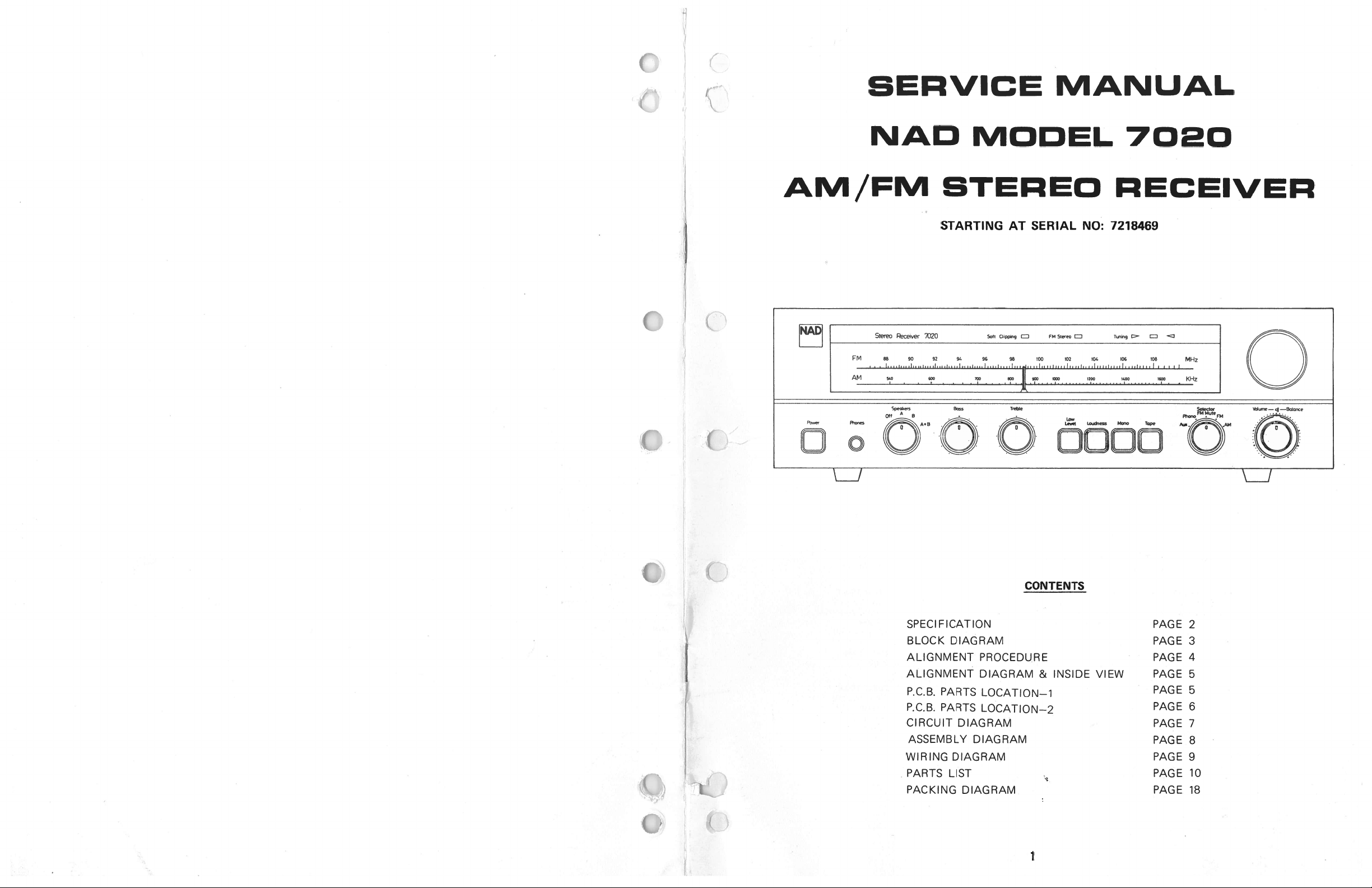
BEPVICE
NAD
MODEL
BTEPEO
STARTING
Stereo
Rece,ver
7020
88
90
!
1
Speak-s
A
oft
A+B
94
92
BOss
•
•
•
MANUAL
7020
RECEIVER
SERIAL
AT
Soft
CIppng
96
98
fretde
.
FM
EJ
.
Steo
J
100
02
Lev(
.
NO:
104
Lou&ess
7218469
Tg
-
06 08
Mono
Tape
ED
MHz
I
:
KHz
5e4ecto
),FMMuteFM
tue—
—8oIac
4
.
...
. .
:
p.jj
Q.)
(
DoOO:c..DcoDD
CONTENTS
SPECI
FICATION
BLOCK
ALIGNMENT
ALIGNMENT
P.C.B.
P.C.B.
CIRCUIT
ASSEMBLY
WIRING
PARTS
PACKING
DIAGRAM
PARTS
PARTS
DIAGRAM
DIAGRAM
LIST
PROCEDURE
DIAGRAM
LOCATION—i
LOCATION—2
DIAGRAM
DIAGRAM
&
INSIDE
VIEW
PAGE
PAGE
PAGE
PAGE
PAGE
PAGE
PAGE
PAGE
PAGE
PAGE
PAGE
c...
‘I
2
3
4
5
5
6
7
8
9
10
18
c
1
Page 2
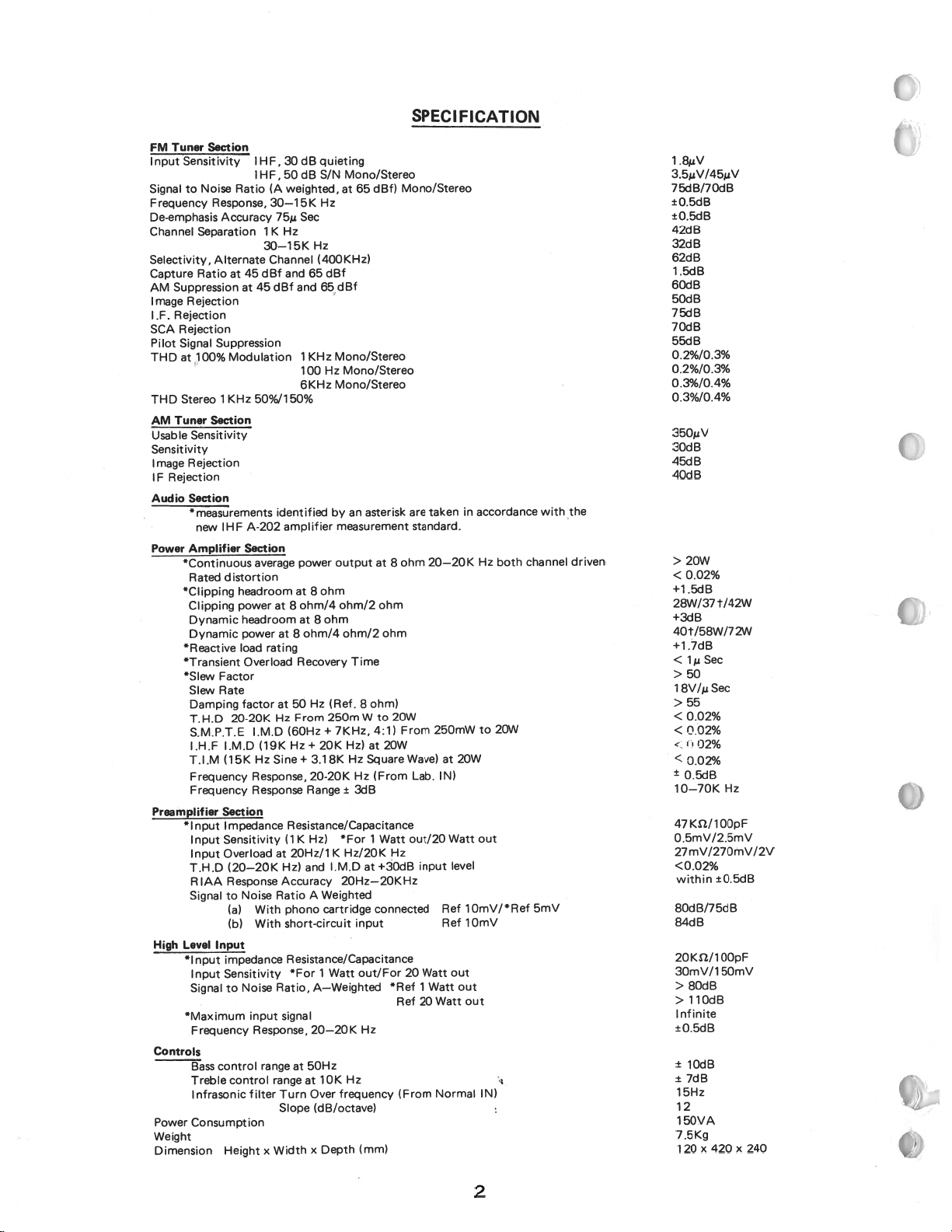
SPEC
I
FICATION
a
FM
Tuner
Sensitivity1HF,
nput
to
Signal
Frequency
De-emphasis
Channel
Selectivity,
Capture
AM
Image
IF.
SCA
Pilot
THD
THD
AM
Suppression
Rejection
Rejection
Rejection
Signal
100%
at
Stereo1KHz
Tuner
Sensitivity
Usable
Sensitivity
Rejection
Image
Rejection
IF
Section
Audio
*
measurements
new
Amplifier
Power
*Continuous
Rated
*Clipping
Clipping
Dynamic
Dynamic
*Rctive
*Transient
*Slew
Slew
Damping
T.H.D
S.M.P.T.E
I.H.F
T.I.M
Frequency
Frequency
Preamplifier
*1
nput
Input
Input
T.H.D
RIAA
Signal
High
Level
*1
nput
Input
Signal
*Maximum
Frequency
Controls
Bass
Treble
Infrasonic
Power
Consumption
Weight
Dimension
Separation
Ratio
Section
dB
30
Noise
1HF,50dB
Ratio(Aweighted,at65
Response,
Accuracy
Alternate
Suppression
Section
IHF
Factor
Rate
Section
Input
control
30—15K
75j,
Sec
Hz
1
K
30—15K
Channel (400KHz)
dBf
and
45
at
45
at
Modulation
50%/i
A-202
Section
average
distortion
headroom
power
headroom
power
load
Overload
factor
20-20K
I.M.D
I.M.D(19KHz+2OKHz)at2OW
Hz
(15K
Response,
Response
I
mpedance
Sensitivity
Overload
(20—20K
Response
Noise
to
With
(a)
With
(b)
impedance
Sensitivity
Noise
to
input
Response,
range
control
filter
HeightxWidth
65
d8f
and
1
KHz
100
6KHz
50%
identified
amplifier
power
at
at8ohm/4
at
at8ohm/4
rating
Recovery
50
at
Hz
From
(60Hz
Sine+
20-20K
Range
Resistance/Capacitance
K
Hz)
(1
20Hz/iKHz/20K
at
Hz)
and
Accuracy
A
Ratio
phono
short-circuit
Resistance/Capacitance
*For
Ratio,
signal
50Hz
at
range
at
Turn
Slope
quieting
Mono/Stereo
S/N
Hz
Hz
dBf
65d8f
Mono/Stereo
Hz
Mono/Stereo
Mono/Stereo
by
an
measurement
output
ohm
8
ohm/2
ohm
8
ohm/2
Time
Hz
(Ref.
8
250m
7KHz,
+
Hz
3.18K
Hz
±
3dB
*For
I.M.D
2OHz—2OKHz
Weighted
cartridge
input
1
Watt
out/For
A—Weighted
20—20
K
Hz
10K
Over
frequency
(dB/octave)
Depth
x
(mm)
dBf)
asterisk
at
ohm
ohm)
W
to
4:1)
Square
(From
1
Watt
+30dB
at
connected
Hz
Mono/Stereo
are
ohm
8
ohm
20W
From
Wave)
out/20
Hz
20
*Ref
Ref 20
(From
takeninaccordance
standard.
250mW
20W
at
IN)
Watt
level
Ref
Ref
out
out
Watt
Normal
Hz
to
out
iOmV/*Ref
lOmV
out
IN)
Lab.
input
Watt
1
20—20K
Watt
both
20W
with
channel
5mV
the
driven
1
.8V
3.5V/45V
75dB/7OdB
±0.5dB
±0.5dB
42dB
32dB
62dB
1.5dB
60dB
50dB
75dB
70dB
55dB
0.2%/0.3%
0.2%/0.3%
0.3%/0.4%
0.3%/0.4%
3501V
30dB
45dB
40dB
>
20W
<0.02%
+1.5dB
t/42W
28W/37
+3dB
40t/58W/72W
+1.7dB
Sec
<lji
>
50
Sec
i8V/t
>55
<0.02%
<0.02%
<.1102%
<0.02%
±
0.5dB
80dB
10dB
7dB
x
Hz
±0.5dB
OOpF
5OmV
420
x
10—70K
47K/100pF
0.5mV/2.5mV
27mV/270mV/2V
<0.02%
within
8OdB/75dB
84dB
2OKW1
3OmV/1
>
>110dB
Infinite
±0.5dB
±
±
15Hz
12
1SOVA
7.5Kg
120
240
2
Page 3
__
k1:
(
:,
!
DIAGRAM
——1
1
L;:::::
B
F,
11JING
GREEN
STRE
(SIGNAL
LED
DRIVE
IF
AMP
Sw-i
r--—-
IF
AMP
LEVEL
DET
---—--
[
-
I.F
T
QUADRATURE
DETECTOR
LEVEL
DET
MUTE
DRIVE
----------------
NING
j
I
AFC
AMP
DRIVER
LED
AUDIO
AMP
MUTE
DRIVE
FM
MUTE
SW-i
AMP
DE—
EMPHASSIS
NETWORK
PLL
DECODER
BUFFER
AM
P
LOW
FILTER
PASS
COMP
DE—
EMPHASSIS
NETWORK
POWER
AMP
TERE)
SUPPLY
DIViDER
LE
SECTiON
SEDNDARY
ANT
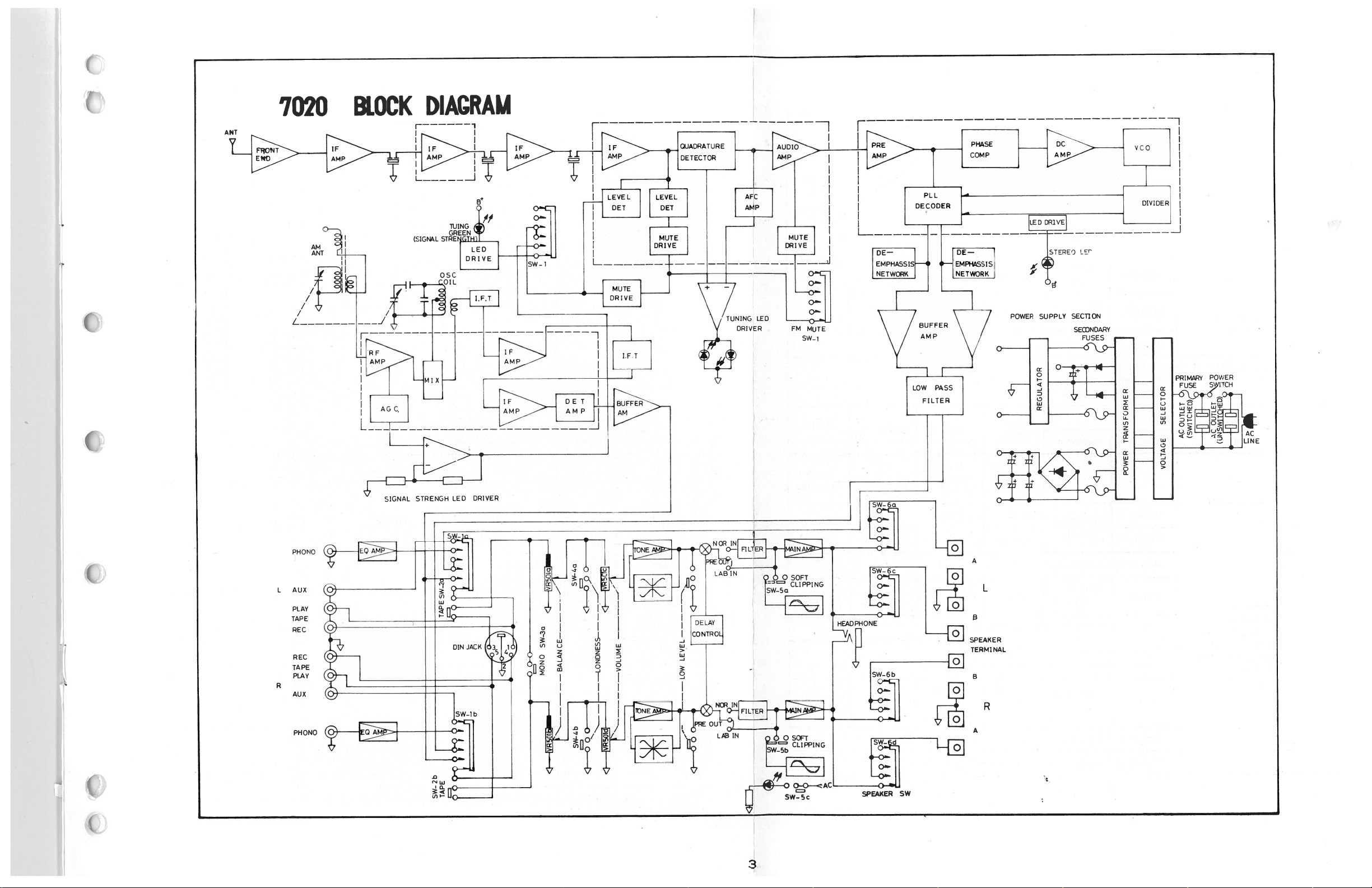
7020
ANT
zZ
BLOCK
J
Ii
RF
I
AMP
C
(,4)
9
-
.
DRIVER
STRENGH
SIGNAL
NC
PH
0
L
AUX
PLAY
TAPE
REC
EC
R
TAPE
PLAY
AUX
PHONO
LED
DINJACK
ib
3T1
S4
w
UI
LjJ
_
r-
th0
r
r
L:Io
-
U,
c
w
\Oi
II
.
-0
SW-Sc
LAB
-
IN
aIING
-€
J
I
.H
r-
c&
[L
SW-6a
SPEAKER
SPEAKER
TERMINAL
f1
BR
A
SW
0
3
Page 4
1
Section
AM
AM
RF
2.
AM
.
IF
—
1
—
2
—
3
FM
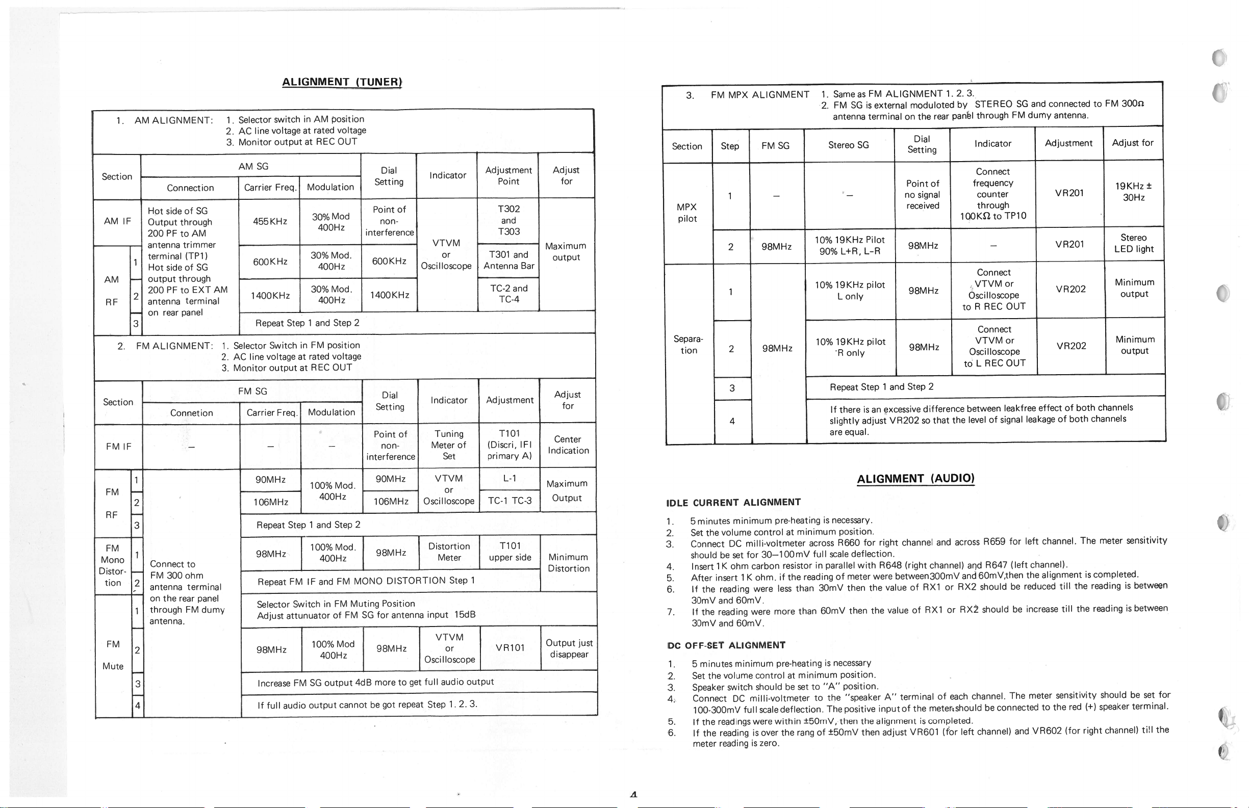
ALIGNMENT:
Connection
Hot
sideofSG
Outputthrough
200
antenna
terminal
Hot
output
200
antenna
on
side
PF
rear
to
trimmer
(TP1)
of
through
EXT
to
terminal
panel
AM
PF
ALIGNMENT:
SG
AM
1
2.
3.
1.
2.
3.
Selector
.
AC
Monitor
AM
Carrier
455KHz
600KHz
1400KHz
Selector
line
AC
Monitor
voltage
line
SG
Repeat
Switch
voltage
output
ALIGNMENT
switch
output
Freq.
Step
in
AM
rated
at
REC
at
Modulation
30%Mod
400Hz
30%Mod.
400Hz
30%
400Hz
-
1
and
FM
in
rated
at
REC
at
position
voltage
OUT
Mod.
Step
position
voltage
OUT
(TUNER)
Setting
Point
interference
600KHz
1400KHz
2
Dial
non-
of
Indicator
VTVM
or
Oscilloscope
Adjustment
Point
T302
and
T303
-
T301
Antenna
TC-2
TC-4
and
and
Bar
Adjust
for
Maximum
output
3.
Section
MPX
pilot
Separa-
tion
FM
MPX
Step
1
2
1
2
ALIGNMENT
SG
FM
—
98MHz
98MHz
Same
as
.
1
FM
SG
2.
antenna
Stereo
SG
V
19KHz
10%
L-R
L+R,
90%
10%l9KHzpilot
only
L
19KHz
10%
R
only
FM
ALIGNMENT
is
external
terminal
Pilot
pilot
moduloted
on
the
Dial
Setting
Pointof
no
signal
received
98MHz
•
98MHz
98MHz
1
rear
3.
2.
STEREO
by
through
panel
Indicator
Connect
frequency
counter
through
100K2toTP10
Connect
VTVMor
Oscilloscope
REC
A
to
Connect
VTVM
Oscilloscope
REC
L
to
FM
and
dumy
connected
antenna.
SG
FM
Adjustment
VR2O1
—
VR2O1
VR202
to
3OOz
Adjust
19KHz±
30Hz
Stereo
light
LED
Minimum
output
for
OUT
or
VR202
Minimum
output
(I
0
OUT
Section
FM
FM
RF
FM
Mono
D
istor-
tion
FM
Mute
IF
—
1
-
2
-
3
Connect
-
FM300ohm
2
antenna
—
on
through
1
antenna.
2
3
4
Connetion
the
rear
—
to
terminal
panel
FM
dumy
FM
Carrier
SG
Freq.
—
90MHz
106MHz
Repeat
98MHz
Repeat
Selector
Adjust
98MHz
Increase
If
full
Modulation
—
Step
IF
FM
Switch
attunuator
FM
output
audio
—
—
100%Mod.
400Hz
1
Step
and
100%Mod.
400Hz
FM
and
FM
in
of
100%Mod
400Hz
output
SG
cannot
2
MONO
Muting
FM
4dB
Dial
Setting
Point
non-
interference
90MHz
106MHz
J
98MHz
[
DISTORTION
Position
for
antenna
SG
98MHz
more
be
got
of
get
to
repeat
Indicator
Tuning
of
Meter
Set
VTVM
or
Oscilloscope
Lstortion
Meter
Step
1
input
5dB
VTVM
or
Oscilloscope
full
audio
2.
1
.
Step
1
output
3.
Adjustment
TiOl
(Discri,
IFI
primary
L-1
TC-1
TC-3
TiOl
side
upper
VR1O1
A)
Adjust
for
Center
Indication
Maximum
Output
Minimum
Distortion
Output
disappear
just
IDLE
.
1
2.
3.
4.
5.
6.
7.
DC
1.
2.
3.
4.
5.
6.
OFF-SET
3
4
CURRENT
the
minimum
volume
DC
minutes
5
Set
Connect
shouldbeset
K
ohm
1
Insert
insert
After
If
reading
the
3OmV
and
the
If
reading
3OmV
and
ALIGNMENT
minutes
5
the
Connect
volume
switch
DC
Set
Speaker
100-300mV
readings
If
the
reading
If
the
reading
meter
ALIGNMENT
control
milli-voitmeter
30—lOOmV
for
carbon
ohm.
1
K
were
6OmV.
were
6OmV.
minimum
control
should
milli-voltmeter
scaledeflection.
full
were
over
is
zero.
is
pre-heating
minimum
at
resistor
reading
the
if
than
less
than
more
pre-heating
minimum
at
set
be
±5OmV,
within
the
rang
is
across
full
in
3OmV
6OmV
“A”
to
to
of
Repeat
If
there
slightly
equal.
are
necessary.
position.
R660
scale
parallel
meter
of
then
necessary
is
position.
position.
“speaker
the
positive
The
then
±5OmV
1
and
Step
excessive
an
is
VR202
adjust
ALIGNMENT
for
right
deflection.
with
R648
were
between300mV
value
the
value
the
then
A”
inputof
the
alignment
then
adjust
Step
so
channel
(right
of
of
terminal
the
is
VR6O1
2
difference
the
that
(AUDIO)
and
channel)
RX1
or
or
RX1
of
each
metershould
completed.
(for
between
level
across
and
and
RX2
RX2
left
of
R659
R647
6OmV,then
should
should
channel.
connected
be
channel)
leakfree
signal
for
(left
be
be
The
and
effect
leakage
left
channel.
channel).
alignment
the
reduced
increase
meter
to
VR602
both
of
both
of
the
till
the
till
sensitivity
red
the
(for
channels
channels
meter
The
completed.
is
reading
reading
shouldbeset
(+)
speaker
right
channel)
sensitivity
between
is
between
is
terminal.
tiH
.
for
‘‘V
the
/1
Page 5
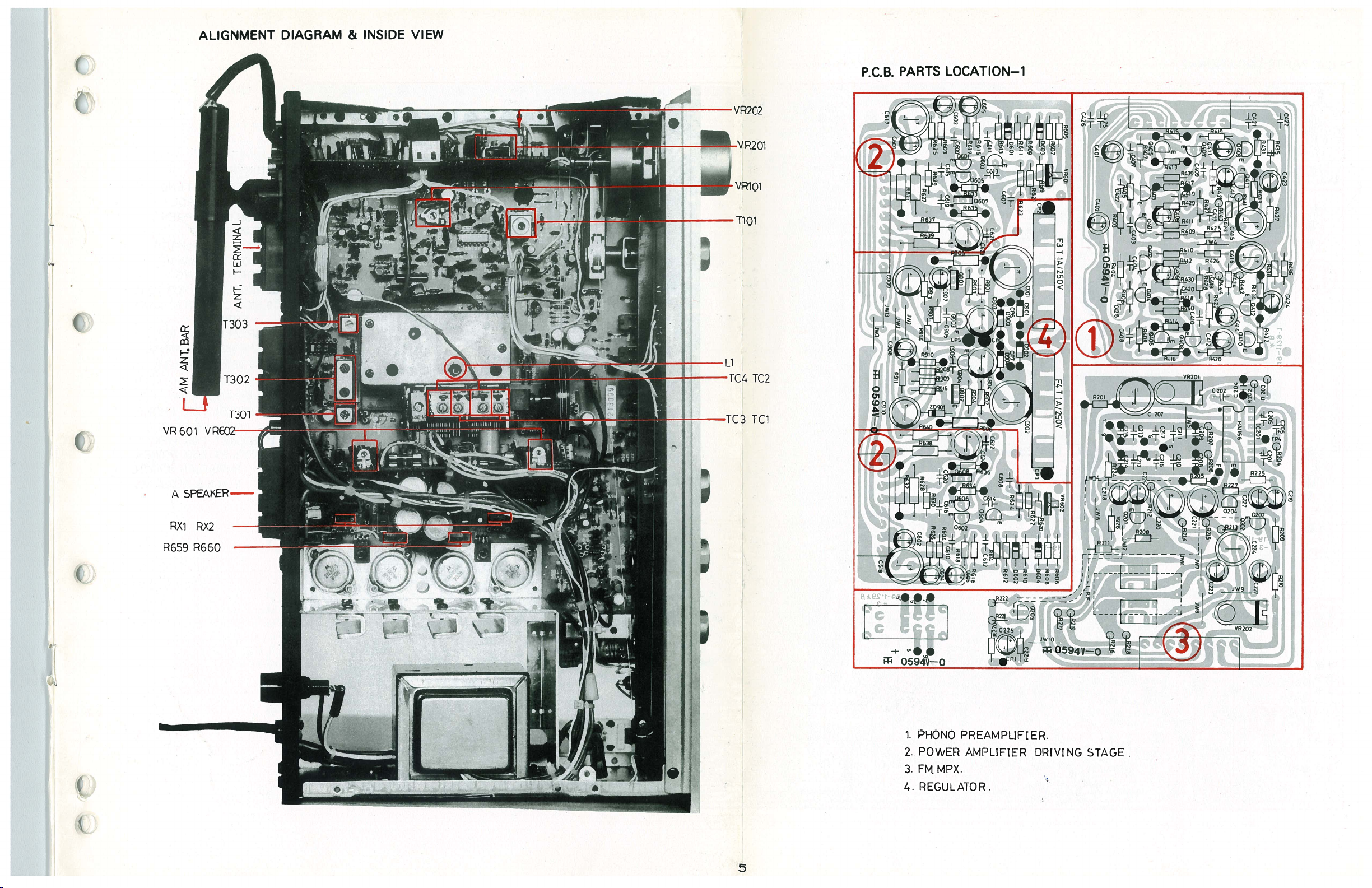
ALIGNMENT
DIAGRAM
INSIDE
&
VIEW
()
0
P.C.B.
-
z
VR2O1
TiQi
TC2
PARTS
LOCATION—i
.*
1
ii’,,’
..J.
VR6O
A
RX1
R659
—
Li
VRGQ2
SPEAKER—
-
TC1
i
1.
PHONO
POWER
2.
PREAMPLIFIER.
AMPLIFIER
DRIVING
STAGE
10
4.
t
5
REGULATOR
Page 6

_____
P.C.B.
1?
0
L
‘SW5
G
F’•
0
0)
I’)
I
x
0’•
B’
L_J
0.
u
.
p12
cPi:
H—
PARTS
0
0
C7)1
.
*.x’
LOCATION—2
7
C703
LAB
.
1
C30
R
2
6
CP4
IHITE
-
XIi[1J
.
-
ICP7
—
‘S
1—
.
-
•CP8ii
ij
.
.-.--,
T301
J?L
HHC3O
9
C301
.
12
C536
D506
CP
RED•
[1
5
P302
—0
R301
—-LEJ—-.,
T302
L
5
C304
1
-H
R303
-L::1--
O0
C’)
T’T
0
©
FRONT
D801
cm—
L].—----D—
D802
J8
C801
L()
h-•f
C.)
il(3
+
2N3055
Q616
•C635
.-
.
‘4
§1
iHö
E
‘
1,
LJ2
crC6262
H
BK602
H-
I
T
t:•’
!
—1EE—R654
I
PREOUT
JR6
•L
tEb
:;
*
‘‘lld
I%
.F2
MJ2955
Q618
MJ2955
Q617
0
0)
to
•0
2N3055
D502
50E:::
51
1A
R
I
ly
T
jJ
0615
3
C521
E
IIIi
t%•
1OKCX2
•
C
I
),_
0
C535
U)
•
•
L
12
1
•1
I
I
I
LJ’’
:
CD
cu
?
J_I
Thi
FL_I;.
I
E0
I
ç
533
LD
E
It
C_i
C911
Fl
Li
Q504
fl1
M••H
-LZJ-R715
T3iW25ov
R643
I
RXi
25
I,
Ir—lö
I
—
O
528
R527
!!-
u
T
•
0
R506
1OKCX2
I
R548
io
17
18
J19
20
J
•
J8_
:1
_
I
g
o
-
CP6BLU
Ir
3II
C)
R305
END
fl801
RRfl2
—EE]---
R803
C802
BLACK
•
—QT
FB127/FEA321
I
C312
I
E
E
0
0)
T
303
-
ii
‘1
:Q
J
2
\IO105
;:
I
r
I
)C)
,
•:
I
,
E
•
EZ
1
o[i
•13
D104
S
DINJACK
314
•?
C,,
©
C-)
31
i
I
‘I
i
J37
J38
cJ
1
J°L.T
O10T
‘
I
l
o44:1©
•
cJ
2
0
T
3
--
—
.
TPJ
JAROO
cO
ri
0
‘R139
0103
—LIR--
S.
IDINJACKRECORD
_,g
•_,
o&oo
!
r
H—
°3nI
&LU
To
!
.
°L
‘-
r.
T
;
Q1O2((.U
-)
A
80103
•
_(
,‘C12k
____:
HSi
0594V—O
.
NC322,
R°
•
•r’.n
0
I
I
C-’
0
L104
J42
cE)
TP2_-rjj_
)
‘D
R13
-“
N
TA
.
.__
lC%4L
TRi5r
o)L-!
T
C114
R116
rT1
R118
C)
•
C
I
•J•
J0z
•_--
.
PLAY
..
r
!
‘.
--.
-
L105
y
TP3
--
S.,
,
LWIi
J
J79
e4
‘—.
-)
1’.-
-,
___1
-
o_z
r
II
I.
•.•.
—
J8w_,-
I
D
-i
R121.J65
1
CD!
J62i
‘
J49
47
CD
)I
C50t1
AUX
J64
J3’
r
I
,
-
.
-
I
I
I
-‘
1J56
I
I
I
I
j
77
‘I
\ç
,
‘
i-I
2OKBx2
5OKMNX2
—ill
11
.L
-
J76
0
PH0yio
CP19•
CP20•
T
0
U)
>
T
GROUND
‘U
1.TUNER
2.TUNER
3.TUNER
4.DELAY
5.HIGH
AM.
FM.
FRONT
CONTROL.
LEVEL
AMPLIFIER.
6.POWER
OUTPUT
SOFTCLIPPING.
7.
8.REGULATOR
9.HIGI-i
CURRENT
SUPPLY.
SPEAKER
10.
11.
SPEAKER
1
2.AT
T
E
NUATOR
PHONES.
LED
13.
ha.
ASSEMBLY.
SOCKET
PREAMPLiFiER.
1
5.
SOCKE
T
16.SOCKET
AMPLIFIFR
STAGE&
END.
PRE
AMPLIFIER
STAGE.
FOR
POWER
SWITCH.
TERMINAL.
FOR
FOR
PHONO
PX.
M
FOR
FOR
POWER
DRIVH43
REGULATO
4
TUNE
4
C
4)
6
Page 7

-
(
I1
7020
(
(
(
CIRCUIT
DIAGRAM
C915
F?
-F7:T1A!250V
Fl
E.-F7:T1A1250V
A1250V
F7
4/2500
47Q0P
16l
C915
sw:
C916
C915
SW
8b
OP
240
RED
BLUE
Er9w
FOR:E2.
BROWN
[R9]8Q
WHITE
;-°-i
-0
YELLOW
FORJFT.T1
BROWN
GREEN
WHJQ
E
ORANGE
120
I
YELLOW
FOR:U3-F7:T1
Note:
This
circuit
the
shematic
is
basic
vary
may
due
diagram,
improvement
to
the
but
actual
in
design.
(
7
Page 8

C
SCALE
SWITcH
Q’TY
2
7020
ASSEMBLY
DIAGRAM
PARTS
ITEM
NO.
11-2047
1
11-2086
2
11-2104
3
11-2141
4
11-2142
5
1-2143
1
6
11-2173
7
11-2182
8
1-2186
1
9
11-2217
10
1
1-2219
1
1
11-3026
12
11-4007
13
11-5056
14
11-5057
15
11-6039
16
11-6044
17
11-6052
18
11-6053
19
11-6072
20
11-7032
21
1-8098-1
1
22
11-8099
23
11-8100
24
11-8119-1
25
11-8170
26
12-1029
27
12-2007
28
12-2012
29
13-2041
30
12-2105
31
12-2106
32
12-2076
33
12-4014
34
12-5019
35
13-5004
36
13-5029
37
13-5018
38
29-5008
39
14-3001
40
14-5003
41
15-2037
42
15-2048
43
15-2049
44
.
15-2051
45
‘
:
1-)
.
.
••_i
15-4010
46
23-3004
47
28-1016
48
DESCRIPTION
BRACKETFORPCB
BRACKET
BRACKET
BRACKET
RIGHTBRACKETFOR
LEFT
BRACKET
BRACKET
BRACKET
BRACKETFORPULLEY
B.
P. C,
LUG
JUMPER
I/O
HEATSINKA
HEATS1NKB
AUX.CHASSISRIGHT
CENTER
AUX.
FRONT
BOTTOM
PULLEYSHAFT
DIAL
FRONTPANEL
DIALPLATE
DIALPERSPEXCOVER
BACK
CONNECTOR
SPEAKER
ANTENNATERMINALSOCKET
PHONE
SOCKETASS’Y
SOCKETASSY
JACK
DIN
POINTER
SPRING
PULLEY
DIAL
TUNING
ANTENNA
AM
TUNING
CORD
GROUND
PLASTICRIVET3x5.5
PLASTIC
SPECIAL
FIBER
DICAST
RUBBER
FOR
RIGHT
BRACKET
FOR
LEFT
FOR
HOLDER
CHASSIS
CHASSIS
CHASSIS
CHASSIS
SCALE
PANEL
TERMINAL
JACK
FOR
DRUM
WHEEL
THREAD
BUSH
SCREW
RIVET
SCREW
WASHER
FO1R
BUSHING
TUNING
FOR
BACK
SELECTOR
LEFT
AND
(6P)
(4P)
TUNING
BAR
4N-4
3x6.5
TUNING
DIALSCALE
DIAL
PANEL
NUT
SOCKET
FOR
SHAFT
THREAD
KNOB
LAMP
:
Q’TY
4
2
2
5
5
5
8
17
34
4
4
4
PHONES,
RUBBER
MYLAR
LAMP
CUSHION
CABINET
DIAL
CUSHION
POWER
DEEMPHASSIS
POWER
SOFT
LAMP
FUSE
MASKER
KNOB
KNOB
1
KNOB
KNOB
CABINET
P.C.B.
P.C.B.
MAIN
P.C.B.
MACHINE
TAPPING
TRIANGLE
WASHER
NUT
SPRING
DESCRIPTION
INSULATION
FOOT
POINTER
FOR
RETAINER
FOR
RETAINER
PERSPEX
TRANSFORMER
SWITCH
CLIPPING
HOLDER
PANEL
FOR
TUNING
FOR
CONTROL
FOR
BALANCE
FOR
PUSH
FOR
TUNER
FOR
PHONO
FOR
AMP,
MPX
FOR
SCREW
SCREW
SCREW
WASHER
MIC
COVER
SWITCH
SWITCH
BUSH
RETAINER
(A)
AND
AMP.
PARTS
NO.
1017
28-
28-1029
28-2015
28-2019
28-2020
28-2023
28-2024
28-2042
29-2045
31-1079F
31-1130
31-1
139f
1-2021
3
32-2005
28-2059
2-3037
1
12-3038
12-307
2-3039
1
50-1024
68
128
90-1
69
90-1129
70
90-1129
71
129
90-1
72
S1BO4+
73
I1OSL-2
S2B03+
74
IQ8SL-2
S5B03+
75
IO8SL-2
A04A07
76
SLO1
N04B07
77
-
13.2SZ
A046
TO7SLO1
R
Page 9

C
:
0
z
C
xl
m
C
z
C)
(I)
P1
0
-4
z
0
!
rn
:
z
—I
—Iji
I’
T
1
H
r—lTrIN
r)
—
D
j
—
RED
I2GREEN
J-3ROWN—
1
C
m
CCRD
POWER
CORD
iD
\
1
C
0
CORD
POWER
_
m
0
C)
0
I
CORD
EEp’C
POWER
-\
POWER
__
I
\
1k))
r\
I
_‘
JL
lDvY
HITE
—
C
ORANGE
GREEN
BROWN
o
—r
IC,
—I-c.--—
_io
o-
-F-—-°=
I
0
9r%4Q-<
C
I
0
TRANSFORMER
E
C
.-
=G-cL------
I
óç;
9—2
12
9-1
1
—OCP4
YELLOW
WH1
—
2
CP
QYL
0
RFfl
E-’
YELLOW
I
•Ez:J
—11
ç,
C
-tJ
129—3
—1
9
1
C
-U
mi
-0
CORD
POWER
-n0rn
II
LLiR4cE
0
>A
‘1
0
m
I
0
P1
BROWN
LLtEN
CORD
POWER
G
E
-
P1
CA)
!
m
_:H
0
F
0
C
<A)
C
m
—a
-
-U
P1
:=j
ORANGE(U4)
—GREEN
C
-n
><
—-—RED(E4
rn
m
P1
(I)
—
E
T
WH
0
—4
z
0
o
-9
,,
:zi
oom
CP14
Ocj
CPl6J
z_<
CPU
—0
....CP13
[L:zr-
—1
L
m
Lf1C
c=
(_)
0
..
:o
10
wco
0
I
-
1_
—
ni
—0
—0
—-0.-
o-
D
—0
VR5O1
Page 10

PARTS
LIST
PARTS
LIST
BK602
,
C209
C21
C213
C215
C217
C219
C221
C223
NO.
PARTS
NO.
30-1049
15-301
1
17-5DR473M
17-5DR473M
17-5DR473M
17-50R103M
..
17-5DR1O3M
175DR473M
17-5DR473M
17-5DR473M
17-5DR473M
17-5DR331M
17-2.5ER1O5Y
17-5DR473M
17-2.5ER1O5Y
17-5DR473M
17-5DR473M
17-1.6E227Y
17-5DR473M
17-2.5ER1O5Y
17-5DR473M
17-5DR473M
17-5DR473M
17-2.5ER475Y
17-5DR1O2M
17-1.6ER1O7Y
17-5DR473M
17-2.5ER475Y
17-160R224M
1
7-5FR473
17-2.5ER475M
17-5U471J
17-1.60R224M
17-1.60R474M
17-1.6E227Y
17-5U821J
1
17-5FR562J
17-5FR123J
17-5U821J
17-5FR682J
17-2.5ER475Y
17-1.6ER1O7Y
17-1.6ER1O6Y
.OS1O7Y
17-1
SYMBOL
BD9O1
BK6O1
clol
C102
C103
C104
cbs
C106
C107
C108
c109
cilo
clii
Cl 12
C113
Cl
14
c115
C116
17
Cl
C118
Cl
19
C120
C121
C122
C123
C124
C125
C127
C201
C202
C203
C204
C205
C206
C207
C208,
C210,
C212,
C214,
C216,
C218,
C220,
C222,
C224
C225 17-5ER1O5Y
C226,
C227
C301
1
7-2.5ER475Y
17-5DR15ODSL
SYMBOL
C302
C303
C304
C305
C307
C308:
C309
C310
C31
1
C312
C313
C314
C31
5
C316
C3’17
C318
C319
C320
C321
C322
C401,
C403,
C405,
C407,
C409,
C411,C412
C413,
C415,C416
C417,
C41
9,
C421,C422
C423,C424
C425
C426
C427,
CSO1,C502
C503,
C505,C506
C507,
C509,CS1O
CS11,C512
C513,
cS1S,
C517,C518
C519
C521,
C523,
jiF
pF
.
REF.
76.00
88.00
5.00
5.00
•
5.00
3.40
3.40
5.00
5.00
5.00
5.00
4.00
8.00
5.00
8.00
5.00
5.00
33.50
5.00
5.00
,
5.00
5.00
5.00
8.00
4.00
14.00
5.00
8.00
16.40
8.90
8.00
9.60
16.40
16.40
33.50
9.60
6.50
.
8.90
9.60
6.50
8.00
14.00
8.00
14.00
8.00
8.00
3.50
DESCRIPTION
A-22
KBLO2
50V
25V
50V
25V
SOy
16V
50V
25V
50V
25V
16V
SOy
25V
16V
50V
25V
SOy
16V
16V
50V
SOy
50V
50V
25V
16V
by
25V
SOy
+—2O%
+75—10%
+—2O%
+75—10%
+—2O%
+50—10%
+—2O%
+75—10%
+—20%
+75—10%
+—2O%
+50—10%
+—2O%
+75—10%
+-.-2O%
+—5%
+75—10%
+_5%
+—2O%
+50—10%
+—5%
+—5%
+—5%
+—5%
+75—10%
+50—10%
+50—10%
+75—10%
+—O.25P
O.O47iF
O.047iF
O.O47jiF
0.01
0.01
O.047iF
0.O47iF
O.O47pF
O.O47iF
330P
1iF
O.O47iF
1iF
O.O47iF
O.O47jiF
22OiF
0.O47iF
1uF
0.O47jiF
0.O47iF
O.O47jiF
4.7iF
1000PF
1OOiF
0.O47iF
4.7iF
0.22jiF
O.O47jiF
4.7iF
47OPF
0.24tF
O.47pF
22O.LF
820PF
O.OO56iF
O.O12iF
820P
0.OO68iF
4.7jiF
1OOuF
lOjiF
1OOiF
4.7iF
4.7iF
15PF
BRIDGE
DIODE
BREAKER
CAPA
DO
DO
DO
DO
DO
DO
DO
DO
DO
CAPA
CAPA
CAPA
CAPA
DO
CAPA
CAPA
CAPA
CAPA
DO
DO
CAPA
CAPA
CAPA
CAPA
CAPA
CAPA
CAPA
CAPA
CAPA
CAPA
DO
CAPA
CAPA
CAPA
DO
CAPA
CAPA
CAPA
CAPA
.
DO
•
CAPA
CAPA
DO
CAPA
CER.
—
—
—
—
—
—
—
—
—
EL.
CER.
CER.
CER.
—
CER.
CER.
EL.
CER.
—
—
EL.
CER. 50V
EL.
CER.
EL.
TA.
MY.
EL.
STY.
TA.
—
EL.
STY.
MY.
—
STY.
MY.
EL.
EL.
—
ELNP
EL.
—
CER.
NO.
.
C402
C404
C406
C408
C410
C414
C418
C420
C428
C504
C508
C514
C516
C422
C524
PARTS
17-5U361J
17-5DR1O3M
17-5DR1O3M
17-5DR1O2M
17-5DR1O3M
17-5DR103M
7-5DR473M
1
17-1.6ER1O7Y
17-5DR1O2M
17-2.5ER475Y
17-5DR1O3M
17-1.6E227Y
7-1
1
17-5FR183J
17-5FR152J
17-5FR183J
17-2.5ER475Y
17-5DR473M
17-5DR1O2M
17-2.5ER225Y
17-2.5ER475Y
17-5DR1O1MSL
17-0.63ER227Y
17-5DR100DSL
17-5DR221
17-1ER476Y
17-1
17-3.5ER476Y
17-5FR473i
7-SF
1
17-5FR222J
17-1.6ER1O6Y
7-5DR473M
1
17-5DR473M
17-5FR1O2J
17-SFR122J
17-5FR224J
17-5DR221MSL
17-5DR473M
17-SF1O4J
17-5F104J
17-5DR1O1
17-5DR1SODSL
17-1ER476Y
17-5DR473M
17-3.5ER476Y
17-1
NO.
.6ER475Y
MSL
ER476Y
R752J
ER476Y
MSL
CAPA
CAPA
DO
—
DO—
DO—
DO—
—
DO
CAPA
CAPA
CAPA
CAPA
CAPA
CAPA
CAPA
DO—
DO—
CAPA
CAPA
P0—
CAPA
DO
CAPA
CAPA
CAPA
CAPA
CAPA
DO
CAPA
CAPA
DO
DO—
CAPA
CAPA
DO
CAPA
DO—
DO—
CAPA
DO
CAPA
DO—
CAPA
CAPA
CAPA
CAPA
CAPA
CAPA
—
—
—
—
—
DESCRIPTION
STY.
CER
EL.
CER.
EL.
CER.
EL.
EL.
MY.
EL.
CER.
EL.
CER.
EL.
CER.
CER.
EL.
EL.
MY.
EL
CER.
MY.
CER.
MY.
CER.
CER.
EL.
CER.
EL.
EL.
50V
50V
16V
SOy
25V
50V
16V
6V
1
50V
25V
SOy
25V
50V
6.3V
SOy
SOy
1OV
35V
50V
16V
50V
50V
SOV
50V
SOy
50V
1OV
50V
35V
1OV
+—5%
+—20%
+50—10%
+—20%
+75—10%
±—20%
+50—10%
+75—i
0%
+—5%
+75—10%
+—20%
t75—1O%
+—20%
+50—10%
+—0.25PF
+—20%
+50—10%
+50—10%
+—5%
+75—10%
+—2O%
+—S%
+—20%
+—S%
+—20%
+—0.25P
+50—10%
+---20%
+50—10%
+50—10%
360PF
O.OljiF
O.O1iF
1000PF
O.01pF
0.O1iF
O.O47jiF
lOOiiF
1000PF
4.7xF
O.01iF
22OiF
4.7iF
O.Ol8jiF
0.0O15iF
O.O18iF
4.7iF
O.O47iF
1000PF
2.2iF
4.7jiF
100PF
22OiF
1OPF
220PF
47iF
47iiF
47iF
O.027.LF
O.OO7SiF
O.0O22iF
1OiF
OO47jiF
O.O47iF
O.0O1.zF
O.OO12.LF
O.22iF
220PF
O.O47jiF
O.1iF
O.lpF
100PF
1SPF
47jiF
O.047iF
47iF
47iF
REF.
9.40
3.40
3.40
4.00
3.40
3.40
5.00
14.00
4.00
8.00
3.40
33.50
8.00
8.90
6.50
8.90
8.00
5.00
4.00
8.00
8.00
3.50
14.00
3.50
4.00
9.00
9.00
14.00
8.90
6.50
6.50
10.00
5.00
5.00
6.50
6.50
20.00
4.00
5.00
13.00
13.00
3.50
•
3.50
9.00
5.00
14.00
9.00
C
C
C
10
Page 11

PARTS
LIST
SYMBOL
C526
C525,
C527,
C528
C529,
C530
C531,
C532
C534
C533,
C535
C601,C602
C604
C603,
C606
C605,
C607,
C608
C610
C609,
C612
C611,
C613,
C614
C615,
C616
C617,
C618
C619,
C620
C621,C622
C623,
C624
C625,
C626
C627,
C628
C629,
C630
C631
,
C632
C635
C536
C537
C701,
C702
C703,
C704
C801
C802
C803
C902
1
C903,
C904
C905,
C906
C907,
C908
C909,
C910
CF1O1
F
C
102
CF
103
DiOl
D
102
D
103
Dl
04
D
105
D106
Dl
07
D501,
D502
D503,
D504
NO.
PARTS
17-SF
NO.
104J
l7-SFR183J
17-1
ER476Y
17-SF
124J
7-1
1
6R684K
17-1
ER1O7Y
17-1
ER476Y
17-
1.6R
105K
17-
1.6R
105K
17-SFR1O2J
7-SF
R272J
1
17-SFR1O2J
1
7-SDR47OMSL
17-SDR
101
17-063E1
1
7-SD
R22OJSL
7-SD
1
R22OJSL
1
7-3.5ER476Y
17-SF
104J
17-SF
104J
17-SD1O4M
17-SD1
04M
R1O2J
17-SF
7-2.SER47SY
1
7-3.5ER476Y
1
7-1
1
ER476Y
ER476Y
17-1
73.SE1
1
1
7-2.
17-1
7-3.SE337Y
1
1
7-3.
7-SD
1
1
7-3.
7-3.5ER476Y
1
08Y
SE337Y
6E
R
10Th’
SE476Y
R221JSL
SER47SY
29-3027
29-3027
29-3027
1044
3030-1019
30-1019
30-1019
30-1019
1019
3030-1019
30-1019
1019
30-
MSL
08Y
CAPA
DO—
CAPA
CAPA
CAPA
CAPA
CAPA
CAPA
DO—
CAPA
DO—
DO—
CAPA
DO—
CAPA
CAPA
DO
—
CAPA
CAPA
DO—
CAPA
DO—
CAPA
CAPA
CAPA
CAPA
DO—
CAPA
CAPA
CAPA
CAPA
DO—
CAPA
CAPA
DO—
CER.
DO
—
DO
—
ZENER
DIODE
DO
—
DO
—
DO
—
DO
—
DO
—
DO
—.
DO
—
DESCRIPTION
MY.
EL.
MY.
AL.
EL.
F
L.
AL.
MY.
CER.
EL.
CER.
EL.
MY.
CER.
MY.
EL.
EL.
EL.
EL.
EL
EL.
EL.
CER.
EL.
FILTER
DIODE
BAW62
SOV
1OV
50V
16V
IUV
OV
1
16V
50V
SOy
6.3V
SOy
35V
50V
SOy
50V
25V
35V
1OV
35V
2EV
16V
35V
SOy
35V
15V
SEE
+—5%
+75—10%
+—5%
+—10%
+50—10%
+75—
1
0%
+—10%
+—5%
+—20%
+50—10%
+—S%
+75—10%
+—5/
+—20%
+—5%
+75—10%
+75—10%
+75—10%
+50—10%
+50—10%
+5Q—iQ%
+50—10%
+—5%
+75—10%
+50—10%
10.7MA8
500mW+—S%
0.1iF
0.018iF
47iF
0l2jiF
068iF
tpF
47iF
1iF
1iF
0.001iF
0.0027iF
0.001iF
47PF
100PF
l000iF
22PF
22PF
47iF
0.1,uF
0.1iF
0.lp.F
0.ljiF
0.001iF
4.7pF
47iF
47iF
47jiF
1000iF
330iF
100.zF
330iF
47.zF
22PF
4.7jiF
47iF
REF.
13.00
8.90
9.00
13.00
38.00
14.60
9.00
25.00
25.00
6.50
6.50
6.50
3.50
3.50
32.50
3.50
3.S0
14.00
13.00
13.00
10.00
10.00
6.50
8.00
14.00
9.00
9.00
93.00
33.50
14.00
33.50
14.00
3.50
8.00
14.00
61
.50
61
.50
61.50
14.80
11.00
11.00
11.00
11.00
11.00
11.00
11.00
11.00
11
Page 12

PARTS
LIST
C
PARTS
LIST
SYMBOL
D505
•
D506
D601,D602
D603,D604
D701,
D702
D703,D704
D801,
D802
D803
D901,
D902
D904
D903,
IC1O1
2
ICO1
1C103
1C210
IC3O1
L101
L102
L103
L104
L105
L106
L601
L602
,
LD1O1
LD1O2
LD1O3
LD2O1
LDZ01
F,
0101
Qi
02
Q103
021
0
.
Q202
Q203
0204
Q301
Q401
,
0402
Q403,
0404
Q405,
Q406
Q407,
Q408
Q409,
Q41
Q411,Q412.
Q501,
Q502
Q503,
Q504
0505,
0506
Q507,
Q508
Q509
NO
‘
LDF2O2
0
PARTS
30-1019
30-1019
30-1
01
9
30-1019
30-1019
30-1019
30-1078
30-1044
30-1002
30-1002
30-3035
30-3070
30-3032
30-3015
30-3036
29-1037
29-1034
29-1034
29-1039
29-1038
92-1051
29-1040
30-1071
30-1071
30-1073
30-1073
30-1073
29-3049
30-2019
30-21
56
30-2156
30-2084-3
30-2084-3
30-2156
30-2156
30-2084-3
30-2085-2
30-2084-3
30-2085-2
30-2096
30-2090-2
30-2096
30-2085-2
30-2084-3
30-2096
30-2090-2
30-2090-2
NO
DESCRIPTION
DIODE
BAW62
DO—
DO
—
DO—
DO
—
DO—
DIODE
ZENER
DIODE
DO
—
IC
IC
IC
IC
IC
INDUCTOR
DO—
,
DO—
DO
—
DO—
DO
—
DO
—
LED
BAV19
DIODE
1N4002
HA1211
LA1
CA1458
HA1156
HA1197
ORANGE
500rnW+—5%
15V
[\
231
lmH+’-lO%
22iH+—10%
22iH+—10%
18#H+—10%
40iH+—10%
2.2iH+—10%
1iH+—10%
TRIANGULAR
DO—
LED
GREEN
RETANGULAR
DO—
DO—
.
PASS
LOW
TRANSISTOR
DO
—
DO—
DO
—
DO
—
DO
—
DO
—
DO
—
DO
—
DO
—
DO
—
DO
—
DO
—
DO—
DO
—
DO
—
DO
—
DO
—
DO—
Fl
19.38KHZ
LTER
2SC930C
81
2SC1
2SC1815GR
BC549C
BC549C
2SC1815GR
2SC1815GR
BC549C
BC559B,
BC549C
BC559B
BC556A
BC546B
BC556A
BC559B
BC549C
BC556A
BC546B
BC546B
5G
R
REF
11.00
11.00
11.00
11.00
11.00
11.00
12.80
14.00
14.00
14.00
115.00
280.00
108.00
180.00
236.00
16.00
15.00
15.00
11.00
15.00
10.00
3.50
15.00
15.00
15.00
15.00
15.00
180.00
23.00
14.00
14.00
22.80
22.80
14.00
14.00
22.80
22.80
22.80
22.80
24.70
24.70
24.70
22.80
22.80
24.70
24.70
24.70
(
C
C:.
C
C
C
69
NO.
•
J
1
J
DESCRIPTION
TRANSISTOR
.
FET
TRANSISTOR
DO
DO
DO
—
—
—
.
DO—
DO
—
DO
—
DO
—
DO—
DO—
DO
—
DO—
DO
—
DO
—
RES.
DO
DO
DO
.
DO—
C.
—
—
—
DO—
DO—
DO
—
DO
—
DO—
DO—
DO—
DO—
DO—
DO—
DO—
DO—
DO—
DO—
DO—
DO—
DO
—
DO—
DO—
DO—
DO—
RES.
RES.
C.
C.
DO—
DO—
DO—
El
BC556A
1
1
BC549C
BC556A
BC556A
BD1
BD139
2N6553
2N6556
2N3055
MJ2955
2SD330
BD1
BD14O
BC546B
BC556A
1/4
W
½W
14W
‘
39
39
±5%
330HM
3900HM
3300HM
HM
3q00
T5KOHM
1OKOHM
2K2OHM
•
330HM
3300HM
1OKOHM
3300HM
56KOHM
12KOHM
2K2OHM
2K7OHM
5K6OHM
2200HM
22KOHM
1000HM
22OKOHM
560HM
100KOHM
100KOHM
68OKOHM
68OKOHM
1KOHM.
±5%
6800HM
1OKOHM
±5%
8200HM
56KOHM
12KOHM
REF.
24.70
104.00
22.80
24.70
24.70
53.20
53.20
80.00
80.00
152.00
152.00
76.00
53.20
58.90
24.70
24.70
1.70
1.70
1.70
1.70
1.70
1.70
1.70
1.70
1.70
1.70
1.70
1..70
1.70
1.70
1.70
1.70
1.70
1.70
1.70
1.70
1.70
1.70
1.70
1.70
1.70
1.70
2.40
1.70
1.70
1.70
1.70
SYMBOL
Q51
0
Q51
1,
Q601
,
Q603,
Q605,
0607,
NO.
Q512
0602
0605
0606
Q608
Q609,Q610
Q61
Q61
2
1
,
Q613,Q614
061
Q61
6
4,
Q617,Q618
Q801
(
Q90l
Q902
Q903
Q904
.
Rl01
R102
R
03
1
04
R
1
(
R105
R106
R107
R
1
08
R
1
09
Rll0
Rlll
R112
R113
(
R114
Rl15
R116
R117
R118
R119
R120
R121
R122
R123
R124
R125
R126
R127
R128
R129
R130
R131
PARTS
30-2096
30-2230
30-2084-3
30-2096
30-2096
30-2083
30-2083
30-21
30-2170
30-2004
30-2114
30-2178
30-2083
30-2082
30-2090-2
.
30-2096
16-1/4CA330J
6-1/4CA391J
1
6-1hCA39
1
6-%CA391
1
16-1hCA153J
16-%CR1O3J
16-%CR222J
1
6-’/4CA330J
6-1/4CA331J
1
16-1/4CR1O3J
16-1/4CA331J
16-%CR563J
16-1/4CA123,i
16-%CR222J
16-%CR272J
16-1/4CR562J
16-1/4CR221J
16-14CA223J
16-1hCR1O1J
16-14CR224J
16-1hCA56OJ
16-1/4CR1O4J
16-’/4CR1O4J
16-1/4CR684J
16-1hCR684J
16-1/4CA1O2J
16-’/2CP681J
16-1hCA1O3J
16-1/4CA821J
l6-1/4CR563J
16-’/4CA123J
12
13
Page 13

SYMBOL
NO.
PARTS
NO.
PARTS
LIST
DESCRIPTION
REF.
C
(
SYMBOL
NO.
PARTS
NO.
PARTS
LIST
DESCRIPTION
REF.
R132
R133
R134
R135
R136
R137
R138
R139
R140
R201
R202
R203
R204
R205
R206,
R207
R208,
R209
R210,
R211
R212,
R213
R214,R215,
R217
R216,
R219
R218,
R220
R221
R222
R223
R224,
R225
R226,
R227
R301
R302
R303
R304
R305
R306
R307
R308
R309
R310
R311
R312
R313
R314
R315
R316
R317
R318
R319
R320
16-14CA331J
16-14CR473J
16-1/4CR223J
16-1/4CR563J
16-1/4CR473J
16-1/4CR473J
16-14CR394J
16-1hCR271J
16-1/4CR181J
16-’/4CA181J
16-1%CR153J
16-14CR223J
16-1hCR1O2J
16-1hCA122J
16-1/4CR392J
1
6-%CA564J
16-1/4CA332J
16-1/4CR271J
16-’/4CR1O2J
16-%CR392J
16-1/4CR1O2J
16-1hCAIO3J
16-14CR223J
16-1/4CR223J
16-1flCA1O4J
1
6-1/4CA332J
16-1/4CA1O4J
1
6-1/4CA470J
16-1/4CR151J
16-1/4CA152J
1
6-1hCA331J
1
6-1hCA562J
1
6-1hCA1
51J
16-%CR1O3J
16-1/4CR1O3J
16-1/4CR272J
16-’ACA181J
16-1/4CR273J
16-%CR273J
16-1/4CA154J
16-%CA331J
16-Y4CA122J
16-1hCR1O4J
16-1hCR1O3J
16-1%CR1O3J
16-’/4CR1O4J
16-%CR1O1J
.
.•
1.70
1.70
1.70
1.70
1.70
1.70
1.70
1.70
1.70
1.70
1.70
1.70
1.70
1.70
1.70
1.70
1.70
1.70
1.70
1.70
1.70
1.70
1.70
1.70
1.70
1.70
1.70
1.70
1.70
1
1
1.70
1.70
1
‘
1
1
.70
1.70
.70
.70
1.70
.70
1
1
.70
.1.70
.70
1
70
1
1
.70’.
1.70
7,Q
1.70
‘
‘
:
1
A
EC.
6-%CA334J
R402
R401
RES.
DO
DO—
DO—
DO—
DO
DO—
DO—
DO—
DO—
DO—
DO—
DO—
DO—
DO
DO
DO—
DO—
DO—
DO
,
DO—
DO—
DO—
DO—
DO—
DO
DO
DO
DO—
DO—
DO
DO
DO
DO—
DO—
DO
DO—
DO—
DO—
DO—
DO
DO—
DO—
DO—
DO—
DO—
DO—
C.
—
—
—
—
—
--
—
—
—
—
—
—
—
‘/4W
±5%
56OKOHM
100KOHM
100KOHM
15OKOHM
100KOHM
100KOHM
3300HM
47KOHM
22KOHM
56KOHM
47KOHM
47KOHM
39OKOHM
2700HM
1800HM
1800HM
15KOHM
22KOHM
1KOHM
1K2OHM
3K9OHM
3K3OHM
2700HM
1KOHM
3K9OHM
1KOHM
1OKOHM
22KOHM
22KOHM
3K3OHM
470HM
1500HM
1K5OHM
3300HM
5K6OHM
1
500HM
1OKOHM
1OKOHM
2K7OHM
1800HM
27KOHM
27KOHM
3300HM
1K2OHM
1OKOHM
1OKOHM
1000HM
170
1.70
1.70
1.70
1.70
1.70
1.70
1.70
1.70
1.70
1.70
1.70
1.70
C
(
1.70
1.70
,
1.70
1.70
1.70
1.70
1.70
1.70
C;
(
1.70
1.70
1.70
1.70
1.70
1.70
1.70
1.70
1.70
C
(
1.70
1.70
1.70
1.70
1.70
1.70
,
1.70
1.70
1.70
1.70
1.70
1.70
1.70
1.70
1.70
C,
(
1.70
1.70
C
,
R404
R403,
R406
R405,
R408
R407,
R41
R409,
R412
R41
1
,
R414
R41
3,
R416
R415,
R418
R417,
R420
R419,
R422
S
R424
R423,
R426
R425,
R427,R428
R429, R430
R431,R432
R434
R433,
R436
R435,
R437,
R438
R439,R440
R441,
R442
R443,R444
R501,R502
R503,
R504
R506
R505,
R507,
R508
R510
R509,
R511,
R512
R514
R513,
R51
5,
R51
R517,
R518
R519,
R520
R521
,
R522
R523,
R524
R525,
R526
R527,
R528
R529,
R530
R531
R532,R534
R533
R535
R536,
R538
R537,
R539
R540,R549
R541
,
R542
R543,
R544
R545,
R546
,
0
!
6
1
6-%CA563J
1
16-1hCA222J
1
6-%CA1
6-1/4CA222J
1
6-’/4CA2O1J
1
16-1
/4CA331J
82J
16-%CA151J
16-%CA221J
16-14CA821J
16-14CA821J
6-1/4CA562J
1
6-1/4CA472J
1
16-1/4CA154J
16-1/4CA1O3J
17-1%CA68OJ
6-1/4CA680J
1
16-%CA681J
6-%CA224J
1
16-%CA153J
16-%CR181J
16-1/4CR824J
16-1/4CR272J
16-1hCR184J
16-%CR823J
1
6-%CA392J
16-1/4CA822J
161/4CR682J
16-%CA682J
16-1
/4CA562J
16-1/4CA680J
6-%CA68OJ
1
16-1
/4CA1
81J
16-1/4CA1O2J
6-’flCR563J
1
16-%CA561J
6-14CA332J
1
6-1hCA1
1
05J
16-1/4CA1O2J
16-%CA331J
16%CR273J
6-1/4CR224J
1
1
6-%CA1
06J
16-1/4CR1O4J
1
6-1hCA681J
16-1/4CR682J
6-1/4C
R
1
1
51
DO
DO
DO
DO
DO
DO
DO—
DO—
DO
DO
DO
DO
DO—
DO—
DO—
DO
DO
DO
DO—
DO
DO—
DO—
DO—
DO—
DO
DO
DO—
DO—
DO
DO
DO
DO
DO
DO
DO
DO
DO
DO—
DO
D3—
DO
DO
DO—
DO
DO—
J
DO
C.
—
—
—
—
—
—
—
—
—
—
—
—
—
—
—
—
—
—
—
—
—
—
—
—
—
—
—
—.
—
—
/4W
±5%
33OKOHM
56KOHM
2K2OHM
1
K8OHM
2K2OHM
2000HM
3300HM
1500HM
2200HM
8200HM
8200HM
5K6OHM
.
4K7OHM
15OKOHM
1OKOHM
680HM
68OHM
6800HM
2200HM
15KOHM
1800HM
82OKOHM
2K7OHM
18OKOHM
82KOHM
3K9OHM
8K2OHM
6K8OHM
6K8OHM
5K6OHM
68OHM
68OHM
800HM
1
1
KOHM
56KOHM
5600HM
3K3OHM
1
MOHM
1KOHM
3300HM
.
27OHM
22OKOHM
OMOHM
1
100KOHM
,
60OHM
,
6K8OHM
500HM
1
14
15
Page 14

PARTS.
LIST
I
PARTS
LIST
SYMBOL
R547,R548
R549
R602
,
R601
R603,
R604
R605,
R606
R607,
R608
R609,
R610
R611,
R612
R614
R613,
R61
R61
5,
R617,R61
R619,R620
,
R622
R621
R624
R623,
R625,
R626
R627,
R628
R629,
R630
R631,
R632
R633, R634
R635,
R636
R638
R637,
R639,R640
,
R642
R641
R643,
R644
R645,
R646
R647,
R648
R649,
R650
R651,
R652
R653,
R654
R656
R655,
R659,R660
R701,R702
R703,
R704
R705,
R706
R707,
R708
R710
R709,
R7’ll,
R712
R713,R714
R801
R802
R803
R804,
R805
R902
R901,
,
R903,
R904
R905, R906
‘
R907
R908
(
NO.
6
8
,
PARTS
NO.
16-1/4CA391J
16-1/4CR1O2J
1
6-%CA681J
1
6-1/4CA562J
1
6-1/4CA561J
1
6-1hCA561J
16-1/4CA223J
16-1/4CA391J
16-1/4CA223J
1
6-14CA222J
1
6-1/4CA222J
16-1/4CA183J
1
6-1/4CA391J
16-1/4CA331J
16-1/4CA270J
16-YCP122J
16-1/4CA470J
16-1/2CP471J
16-’/4CA680J
16-1/4CA391J
1
6-%CP1
22J
16-1/2CP122J
1
6-’/4CA391J
16-1/4CA181J
16-1/4CA181J
16-1A100J
16-1A221J
16-1A1O1J
16-1/4CA334J
16-1/4MA330J
16-1hCR1R0J
16-1/4CR224J
16-%CR682J
16-1/4CA331J
16-Y4CA561J
16-1/4CA561J
16-1hCA331J
16-1/4CR682J
16-%CP100J
1
6-1/4CA1
16-%CA1
22J
22J
16-1/2A5R6J
16-1/4CA122J
16-1/4CA122J
16-1A100J
16-%CA122J
16-%CA122J
DESCRIPTION
RES.
C.
DO—
DO
—
—
DO
DO
—
DO
—
DO—
DO—
—
DO
DO
—
DO
—
DO—
—
DO
DO
—
DO
—
RES.
RES.
RES.
.
RES.
DO
R
ES.
C.
C.
C.
C.
—
C.
DO—
RES.
C.
DO—
DO
—
RES. MOF
DO—
DO—
RES.
RES
RES.
C.
MF.
C.
DO—
DO—
—
DO
DO
—
DO—
DO—
DO—
.
DO—
DO
DO
RES.
RES.
DO
RES.
RES.
DO
—
—
MOF
C.
—
MOF
C.
—
‘4W
±5%
3900HM
1KOHM
6800HM
5K6OHM
5600HM
5600HM
22KOHM
3900HM
22KOHM
2K2OHM
2K2OHM
‘
18KOHM
3900HM
3300HM
270HM
/W
1
/4W
1/2
W
‘/4W
±5%
±5%
±5%
±5%
1K2OHM
470HM
4700HM
680HM
3900HM
%W
±5%
K2OHM
1
1K2OHM
1/4
W
±5%
3900HM
1800HM
1800HM
1W
100HM
±5%
‘
2200HM
1000HM
1
/4W
1
/4W
%W
±5%
±5%
±5%
33OKOHM
33OHM
1OHM
22OKOHM
6K8OHM
3300HM
5600HM
5600HM
3300HM
6K8OHM
100HM
K2OHM
1
K2OHM
1
5.6OHM
1/2
W
‘I4W
1W
%W
±5%
±5%’
±5%
±5%
K2OHMi
1
1
K2OHM1
100HMI
1
K2OHM1
K2OHMI
1
REF.
1.70
1.70
1.70
1.70
1.70
1.70
1.70
1.70
1.70
1.70
1
1.70
1.70
1.70
1.70
2.40
1.70
2.40
1.70
1.70
2.40
2.40
1
.70
1.70
1.70
7.50
7.50
7.50
1.70
2.70
1.70
1.70
1.70
1.70
1.70
1.70
1.70
1.70
2.40
1.70
1.70
7.50
1.70
1.70
7.50
1.70
1.70
.70
C,
C
(I
C,
C
I
139
129A
8
22J
82J
NO.
RES.
DO—
DO
DO—
DO
DO—-
SWITCH
DO—
DO
DO—
DO
DO—
DO—
.
FM
AM
AM
AM
SEMIFIXED
DO—
DO—
DO—
VOLUML
TONE
ZENER
C.
—
—
ROTARY
PUSH
—
SLIDE
ROTARY
—
POWER
SLIDE
VOLTAGE
DETECTOR
COI
OSC
IFT
WITH
FT
&
CONTROL
DIODE
DESCRIPTION
14W
SRZ
—
4
Key—2U
SELECTOR
COIL
L
CERAMIC
RES.
BALANCE
500niW+—5%
22V
±5%
1
1
15KOHM
1
12KOHM
L5
SSB42
SRZ-44
55B23
10.7MHZ
FILTER
20KB
10KB
5KB
20KB
CONTROL
1OKCx2
K2OHM
1000HM
K2OHM
K8OHM
2OKBx2
5OKMN
&
REF.
1.70
1.70
1.70
1.70
1.70
1.70
265.00
220.00
75.00
220.00
300.00
53.00
169.20
96.00
25.00
134.00
25.00
18.00
18.00
18.00
18.00
400.00
180.00
20.00
T
SYMBOL
NO.
R909
R910
1
R91
R913
R91
4
R915
swi
SW2-Sw5
5W6
‘
5W7
SW8
5W9
SW1O
T101
T301
T302
T303
VR1O1
VR2O1
VR202
(
VR6O1,
VR602
VR5O1
VR502,
VR503
ZD9O1
PARTS
16-%CA122J
16-1hCA1O1J
1
6-1hCA1
16-1hCA153J
1
6-1/4CA1
16-’ACA123J
31-1135
31-1094F
31-1
31-1024
31-1
311079*F
31-1121
29-3008T
29-301
29-3032
29-3029
29-4023
29-4077F
29-4022
29-4115F
29-4103A
29-4075F
30-1041N
16
17
Page 15

9JAC1cNGDIA
I
(
(
C
18
 Loading...