

Nad 300 Service Manual
$tRUIET
lllr[ilufll
,Z-ftCC
'/t.t'J?.:':
STEREO
xrr,;
RECEIVER
aj ,,
.i1!,
,?':]i !r.:n!
"
r-;;.$SS.$$S
mm$Smp
1r \:rLr!qi*rnt4{r
*!* #,*
q;"
w_
.-
[tr]*irlilJ
t'rt{t
,Y.
I
'
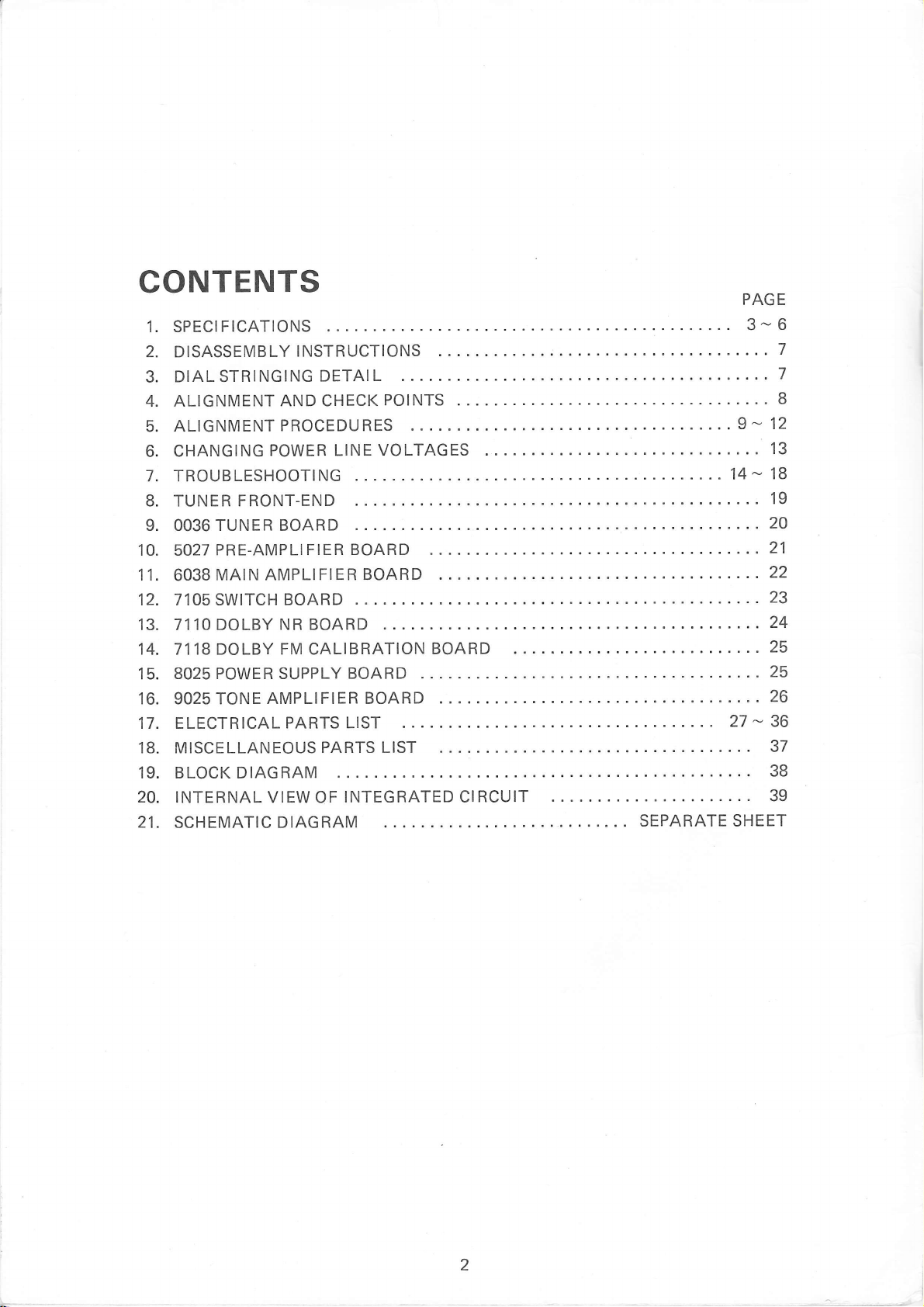
CONTENTS
1.
SPECIFICATIONS
2.
DISASSEMB
DIAL STRINGING
3.
4.
ALIGNMENT
5.
ALIGNMENTPROCEDURES
CHANGING
6.
7.
TROUBLESHOOTI
8.
TUNER
9.
OO36TUNERBOARD
10.
11.
12.
13.
14.
15.
16.
17.
18.
19.
20.
21.
PRE-AMPLIFIER
5027
MAIN
6038
7105 SWITCH BOARD
7110
DOLBY
7118
DOLBY
BO25 POWER SUPPLY BOARD
9025 TONE
ELECTRICAL
M ISCE LLAN EOUS
BLOCK DIAGRAM
INTERNAL VIEW OF
SCHEMATIC
LY I NSTRUCTI ONS
DETAIL
AND CHECK
POWER LINE
NG
FRONT-END
POINTS
VOLTAGES
BOARD
AMPLIFIER BOARD
NR BOARD
FM CALIBRATION
AMPLIFIEB BOARD
PARTS LIST
PARTS LIST
INTEGRATED CIRCUIT
DIAGRAM
BOARD
PAGE
3-
....9-
..,..
......
SEPARATE SHEET
12
13
18
19
...2O
21
22
23
24
25
25
26
....
27 - 36
37
38
39
6
7
7
I
2
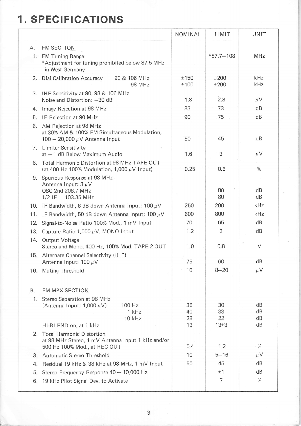
1.
SPECIFICATIONS
A. FM SECTION
FM Tuning Range
1.
*Adjustment
in
West Germany
2. Dial
4.
5.
6.
7.
Calibration
IHF Sensitivity at
Noise and Distortion:
lmage Rejection at 98
lF Rejection at 90
Rejection at 98
AM
at 30% AM & 100%
100
Limiter
at
20,000
-
1 dB Below
-
for tuning
Accuracy 90 & 106
pV
Sensitivity
Maximum Audio
Total Harmonic Distortion at
(at
Spurious
9.
Antenna
400 Hz
2nd 206.7 MHz
OSC
lOOo/o
Response at
lnput:
3
1/2lF 103.35 MHz
lF
10.
1 1
12. Signal-to-Noise
13. Capture
14. Output
15. Alternate
16.
Bandwidth,6 dB
lF Bandwidth, 50 dB
.
Ratio 1,000
Voltage
Stereo and
Antenna lnput: 100
Muting
Mono, 4OO H2,100%
Channel
Threshold
Ratio 100%
prohibited
90, 98
MHz
MHz
FM Simultaneous
Antenna
-30
MHz
&
106
dB
lnput
98 MHz TAPE OUT
Modulation,
98 MHz
pV
down Antenna
down Antenna
Mod.,
prV,
MONO
Selectivity
pV
(lH
below 87.5 MHz
98
MHz
Modulation,
pV
1,000
lnput:
lnput:
1 mV
lnput
Mod. TAPE-2
F)
MHz
MHz
lnput)
100pV
100
lnput
pV
OUT
NOMINAL LIMIT
*87.7-108
r
150
t'100
1.8
83
90
1.6
o.25
250
600
70
1.2
1.0
75
10
t
200
x2OO
2.8
73
75
0.6
80
80
200
800
65
2
0.8
60
B-20
UN
MHz
kHz
kHz
pV
dB
dB
dB
pV
o/
dB
dB
kHz
kHz
dB
dB
dB
pV
IT
/o
FM
B.
1. Stereo Separation at
MPX SECTION
(Antenna
Hl-BLEND
98
lnput: 1,000
on, at
1 kHz
2. Total Harmonic Distortion
MHz
at 98
500
Automatic Stereo Threshold
3.
4. Residual 19
5. Stereo
19 kHz
6.
Stereo,
Hz 100%
kHz
Frequency Response
Pilot
Mod.,
& 38
Signal
1
mV
at
Dev. to Activate
MHz
pV)
Antenna
REC
OUT
kHz
at
40 - 10,000
Hz
100
kHz
1
kHz
10
1 kHz
lnput
98 MHz, 1 mV
Hz
and/or
lnput
35
40
28
13
o.4
10
50
30
33
22
1 313
1.2
5-16
45
t1
7
dB
dB
dB
dB
o/
/o
sV
dB
dB
o/
/o
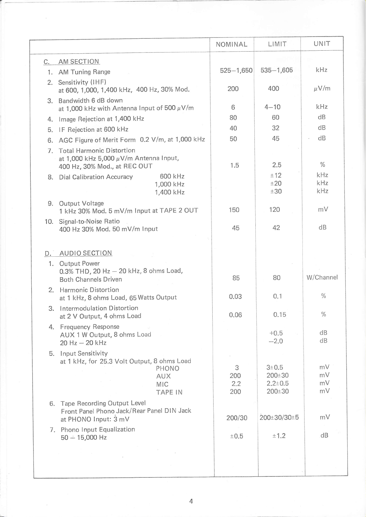
AM SECTION
C.
1. AM
Tuning
2. Sensitivity
600,
at
Bandwidth
3.
1,000
at
lmage
4.
lF Rejection
5.
Figure
AGC
6.
7. Total
8. Dial
Harmonic Distortion
1,000
at
4OO H2,30%
Calibration
Range
(lHF)
'1,000,
dB
6
kHz with
Rejection
at 600
of
kHz 5,000
Mod., at
kHz,
1,4OO
down
Antenna
1,400
at
Merit
kHz
kHz
Form
pYlm
REC OUT
Antenna
Accuracy
H2,30%
400
lnput of
V/m, at
0.2
500
lnPut,
600
1,000
1,400
Mod.
pVlm
1,000
kHz
kHz
kHz
kHz
NOMINAL
525-1,650
200
6
80
40
50
LIMIT
535-1,605
400
4-10
60
32
45
9. Output
kHz
1
Signal-to-'Noise
10.
Hz 30%
400
AUDIO
D.
1. Output
THD,
0.3%
Both Channels
2. Harmonic
kHz,8 ohms
1
at
lntermodulation
3.
at2Y Output,4
Frequency
4.
1 W
AUX
Hz
20
lnput Sensitivity
5.
kHz,
1
at
Voltage
Mod. 5 mV/m
30%
Mod.
SECTION
Power
2O Hz
Distortion
Response
Output,
2O kH,z
-
for
25.3
Ratio
50
20
-
Driven
Load,
Distortion
ohms
8 ohms
Volt
lnput at
mV/m
kHz,
65Watts
Load
Load
Output,
lnPut
B
ohms
TAPE
Load,
OutPut
B ohms
PHONO
AUX
Mrc
TAPE
2
Load
IN
OUT
0.15
+0.5
-2.O
310.5
200130
2.2tO.5
200t30
W/Channel
o/
/o
o/
/o
dB
dB
6.
7.
Recording
Tape
Panel
Front
PHONO lnput:
at
15,000
-
lnput
Phono
50
OutPut
Phono
Jack/Rear
i mV
Equalization
Hz
Level
Panel DIN
Jack
200t30/30t5
t1.2
4
NOMINAL
LIMIT
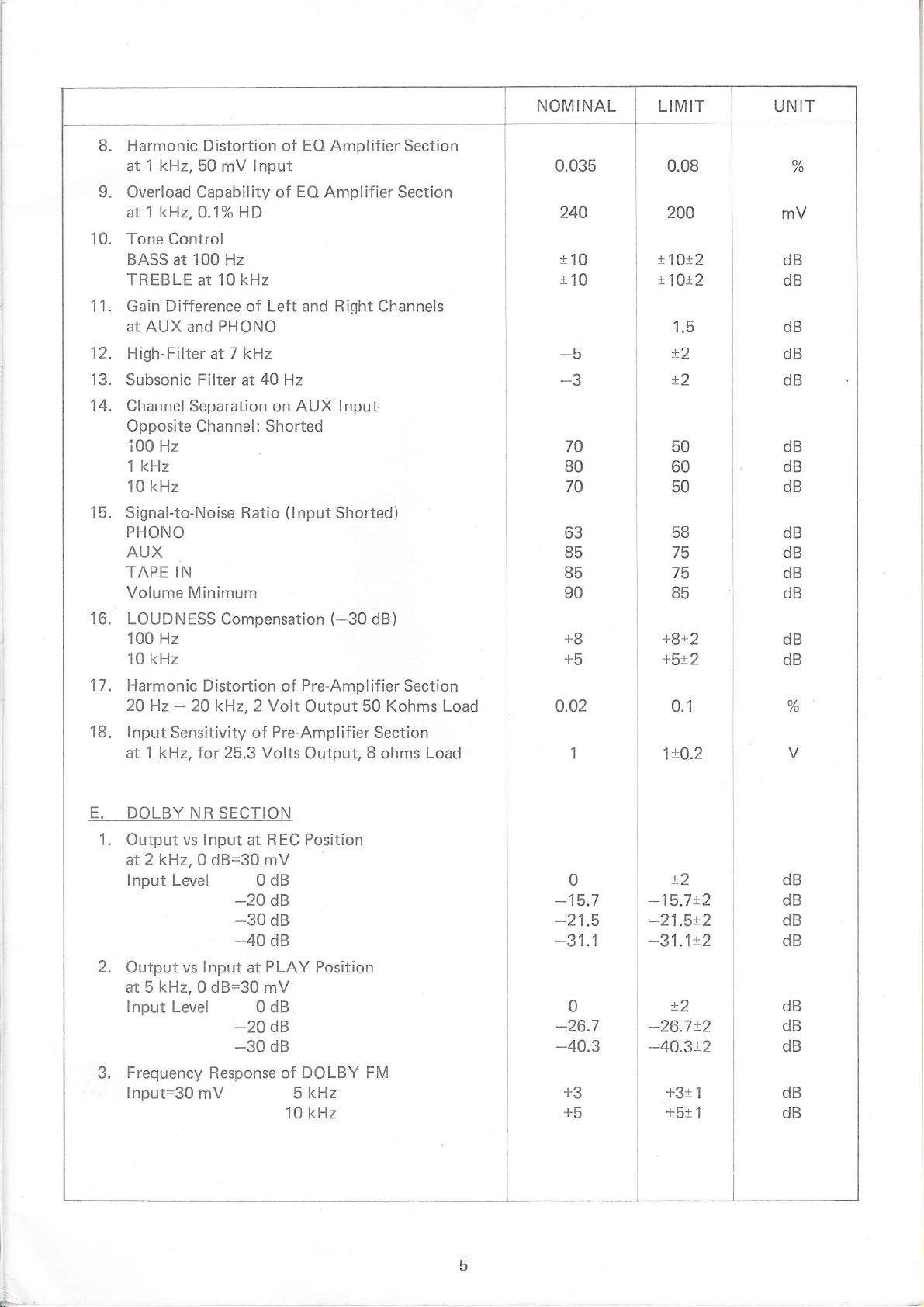
UNIT
Harmonic
8.
at 1
9.
Overload Capability of
1
at
10. Tone
BASS
TREBLE
kHz,
kHz,
Control
at 100
50
0.1% HD
at
Distortion of
lnput
mV
Hz
10 kHz
EO
Amplifier Section
EO Amplifier
Section
11. Gain Difference of Left and Right Channels
at
AUX and
12. High-Filter
13. Subsonic Filter
14. Channel
Opposite Channel : Shorted
i00 Hz
kHz
1
kHz
10
15.
Signal-to-Noise Ratio
PHONO
AUX
TAPE IN
Volume
16. LOUDNESS
100 Hz
10 kHz
17. Harmonic
20
Hz
lnput
18.
Sensitivity of
at 1 kHz, for 25.3 Volts
PHONO
kHz
at7
40
Hz
at
Separation on AUX
(lnput
Minimum
Compensation
Distortion
20 k{z,2 Volt
-
of
Pre-Amplifier
lnput.
Shorted)
(-30
dB)
Pre-Amplifier
Section
Output 50 Kohms Load
Section
Output,
8
ohms
Load
0.035
240
t10
t10
-5
-3
70
80
70
63
85
85
90
+8
+5
o.o2
1
0.08
200
t1Ot2
!1O!2
1.5
t2
t2
50
60
50
58
75
75
85
+8t2
+5t2
0.1
1!O.2
mV
dB
dB
dB
dB
dB
dB
dB
dB
dB
dB
dB
dB
dB
dB
o/
/o
V
E.
DOLBY NR
1 . Output vs lnput
at2k1z,0
lnput
2.
Output vs
at 5 kHz, 0 dB=30
lnput
Frequency
3.
lnput=3O
dB=30 mV
Level 0 dB
lnput
Level 0 dB
Response of DOLBY FM
mV
SECTION
R EC Position
at
dB
-20
_;3
3B
PLAY
at
mV
dB
-20
dB
-30
Position
kHz
5
10 kHz
0
-15.7
-21.5
-31.1
0
-26.7
-40.3
+3
+5
t2
-15.7t2
-21.5t2
-31.1t2
t2
-26.7!2
-40.3x2
+31
1
+5r
1
dB
dB
dB
dB
dB
dB
dB
dB
dB
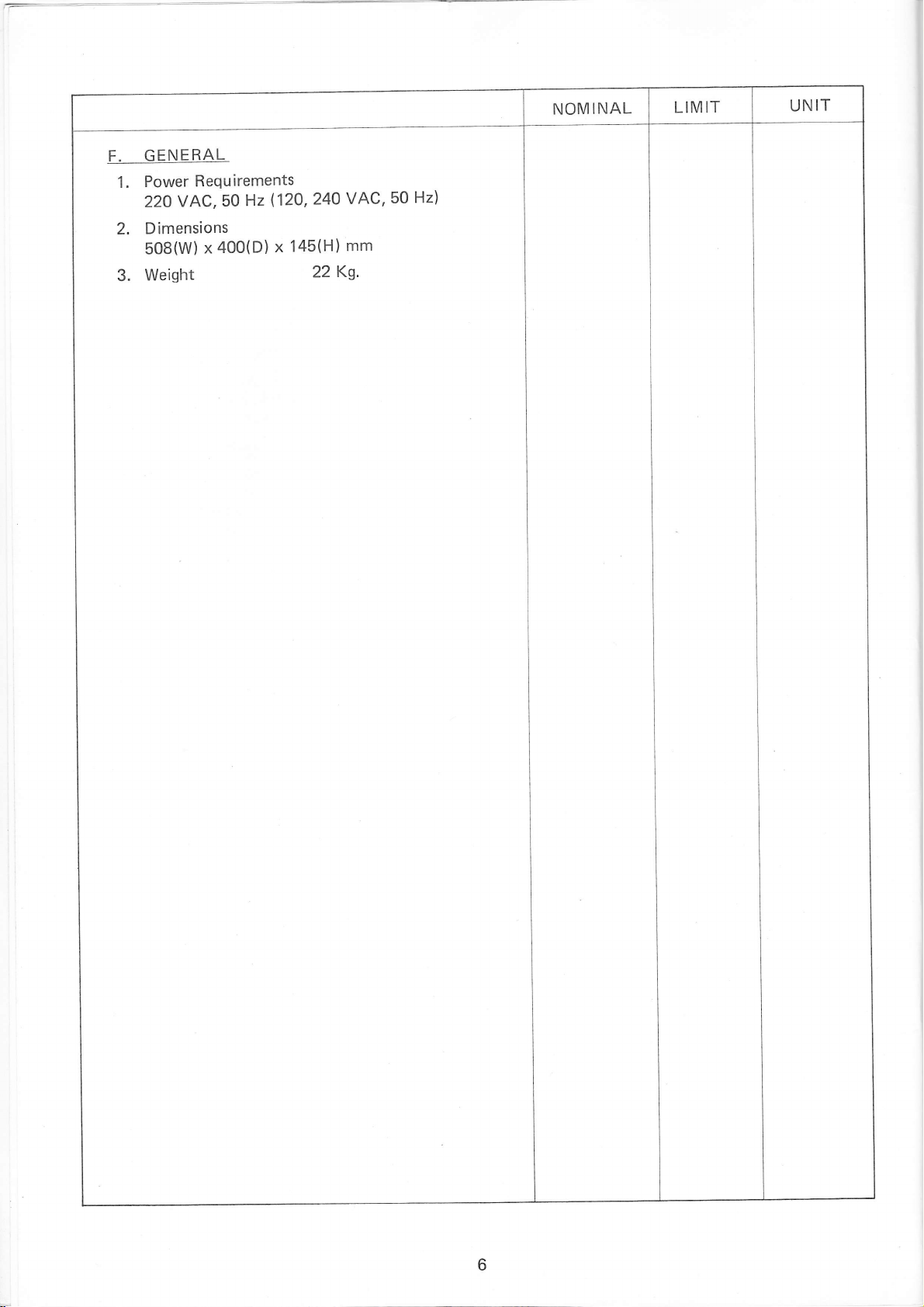
F. GENERAL
Power
1.
22OVAC,50
Dimensions
2.
508(W)
Weisht
3.
Requirements
x
Hz
400(D)
(12O,24O
145(H)
x
22
VAC,50
mm
Ks.
Hz)
NOMINAL
LIMIT
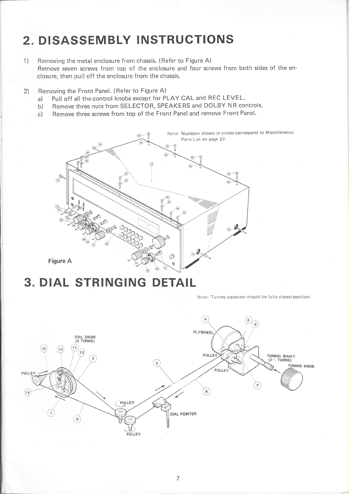
2. DISASSEMBLY
INSTRUCTIONS
1)
Removing the metal enclosure
Remove
closure, then
2l
Removing
a)
b) Remove
c)
seven screws
pull
the
Pull
Remove
off
all the
off
Front
three nuts
three screws
from top
the
enclosure
Panel.
control
from
from chassis.
of the enclosure and
f rom the chassis.
(Refer
from top of
to
knobs except
SELECTOR,
!D\
Er^ \
q.P9
,
r
(Refer
Figure A)
for
SPEAKERS
Front
the
I
to Figure
PLAY
CAL
Panel
Note: Numbers
Parts
A)
four screws
REC LEVEL.
and
DOLBY
and
remove
and
in circles
shown
on
List
Page
from both sides
NR controls.
Panel.
Front
correspond
37.
of
Miscellaneous
to
the en-
3.
Figure
A
DIAL
\i' /
STRINGING
DIAL
DRUM
(2
TURNS)
6l)
Y6;)
l'/e
t/r
. PULLEY
DETAIL
Note: Tuning capacitor
should be
fully
closed
position
'-V)
PIJLLEY
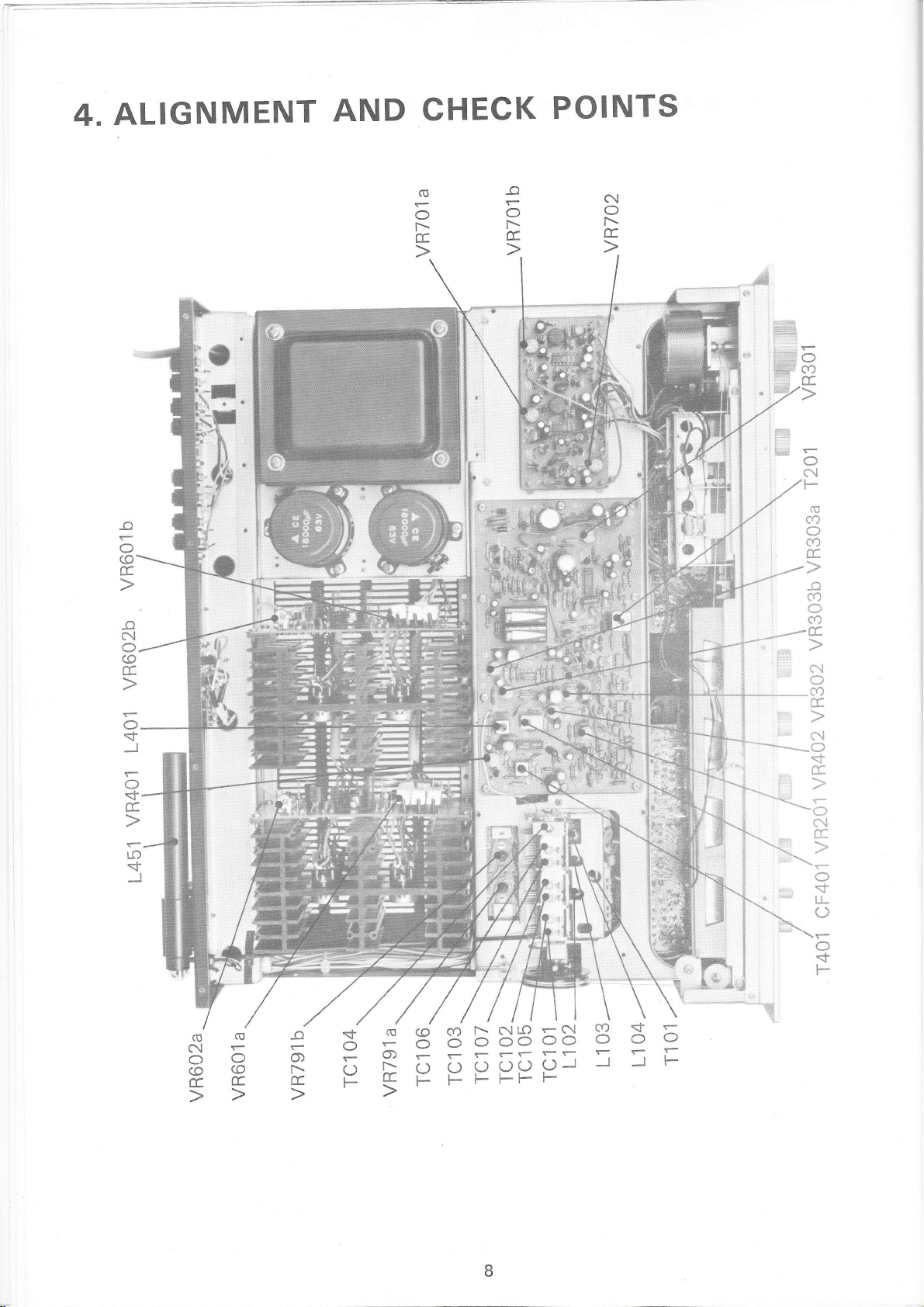
4.ALIGNMENT
AND
CHECK
POINTS
_o
O
(o
E.
_o
N
O.
(0
E.
O.
J
r
O
E.
LO
_o
o
F
E.
N
o
r\
E.
O
CD
E.
o
C\l
F
ca
O
co
E.
(U
*
"I
\
(o
O
F
E.
ei
,
c)
,8.
r.l
a)
C')
ff.
.,/
*\(}
f{
0[
J
O
<l
LL
O
F
c)
F
(gO
Nr
OO
(o
EE
(o
F-
FF
rN
oo
rf
F
l\ N()
cD
o oo
ij
-
SiJi:c;o-r
F
F
CD
S
o o
-
I I
o
=
F
&
&
&,&Ju$
,ii

ALIGNMENT
5.
PROCEDURES
not attempt
Do
EOUIPMENT
Signal Generator
AM
1.
2.
Oscilloscope
alignment unless
DESCRIPTION
3. AC Voltmeter
FM Signal Generator
4.
IF
AM
Output
Set SELECTOR switch
RF ALIGNMENT
&
generator
signal
of
SIGNAL
STEP
GENERATOR
COUPLING
1
2
Refer Fig.
as Step
Same
5. Stereo
Audio
6.
7. Distortion
DC Voltmeter
8.
should
to AM.
51
S.IGNAL
GENERATOR
F REOUENCY
455
(400
1
600
(400
following equipment
the
Modulator
Generator
meter
higher
no
be
RECE
SETTI
Point of non-
i nterference.
(on/about
Hz
kHz
Mod.)
600
Hz
kHz
Mod.)
600
is available.
Frequency
9.
than necessary
IVER
DIAL
NG
AC
to
kHz)
kHz
jack.
Same
Counter
to obtain
INDICATOR
Voltmeter
TAPE
OUT
as step
an output
ADJUSTMENT
T401
Both sections
CF4O1
1401
1
L451(ANT
reading.
(RF
Coil)
(OSC
Coil)
Coil)
REMARKS
Adjust
for
maximum
reading.
Adjust
for
maximum
i ng.
read
3
Same as
4 Same
5
Same
Step
as Step
as Step
Loop
Antenna
[--00
TC107
(OSC
Trimmer)
kHz
1
1400
(400
Hz
Mod.)
1400 kHz
Same
as
step
1
TC105
(ANT
Trimmer)
TC106
(RF
Trimmer)
Adjust
maximum
reading.
Repeat
(2)
Adjust
kHz
1
1000
(400
Hz
Mod.)
1000 kHz
Same
as step
V
R4O2
1
150
Audio
and
mV
for
steps
(3)
for
Output
1000
(400
1
SG
level
cm
Mod.)
Hz
output
28mV/m
kHz
1000
TUNER
FRONT
TC105, TC106
TC107
END
SIGNAL
Meter
AM/FM
L401,
cF401
VR4O1
IF
T401,
maximum
read
on SIGNAL
meter
kHz
Adjust
for
i ng
Fis.1
I
I
I
AM
ALIGNMENT
CONNECTION
ALIGNMENT
AND
RF
FM
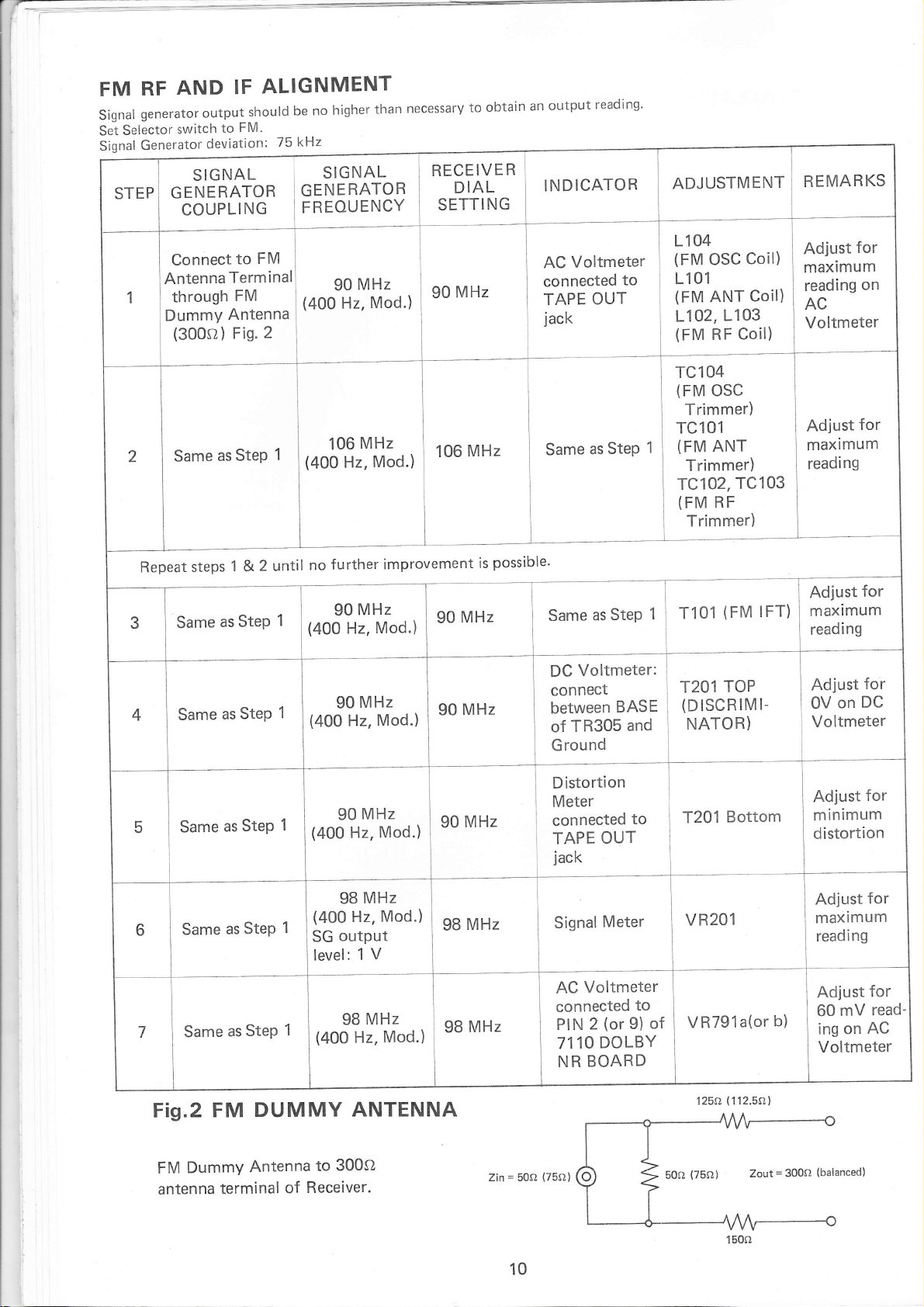
Signa|generatoroutputshouldbenohigherthannecessarytoobtainanoutputreading.
Selector
Set
Signal
switch
Generator
GENERATOR
COUPLI
IF
FM'
to
deviation:
SIGNAL
NG
kHz
75
SIGNAL
GENERATOR
FREOUENCY
RECEIVER
DIAL
SETTING
tNDTCATOR i
AOlUsrn/lerur
REMARKS
Connect
Antenna
through
DummY
(300sl)
Same
Repeat
steps
Same
Same
to
Terminal
FM
Antenna
Fig'
Step
as
1 &
as Step
Step
as
FM
2
1
2 until
1
1
MHz
90
(400
Hz.
Mod.)
(oolofi.Yil'"0''
further
no
(4OO
(400
90
90
improvement
MHz
Mod.)
Hz,
MHz
Mod.)
Hz,
i
'06
MHz
is
possible'
Voltmeter
AC
connected
TAPE
OUT
jack
as
Same
as
Same
Voltmeter:
DC
connect
between
TR305
of
Ground
to
Step
Step
BASE
and
1104
(FM
L1 01
(FM
L102,
(FM
TC104
(FM
TC101
(FM
1
TC102,
(FM
T101
1
T2O1
(DISCRIMI-
OSC
ANT
L103
Coil)
RF
OSC
Trimmer)
ANT
Trimmer)
TC103
RF
Trimmer)
(FM
TOP
NATOR)
Coil)
Coil)
IFT)
Adjust
for
maximum
reading
AC
on
Voltmeter
Adjust
for
maximum
reading
Adjust
for
maximum
reading
Adjust
DC
on
0V
Voltmeter
for
as
Same
as
Same
as
Same
Fig.2 FM
Dummy
FM
antenna
terminal
1
Step
1
Step
1
Step
DUMMY
Antenna
Receiver.
of
r*o3o-1il'"a.,
9BMHz
Mod.)
Hz,
!4^00
output
SG
V
1
level:
MHz
98
(400
300o
to
Mod.)
Hz,
ANTENNA
I
i
oo
n,
uu'
,r,
Zin
=
5012
Distortion
Meter
connected
TAPE
jack
L
signrr
I
Voltmeter
AC
connected
PIN
7110
NR
(75o)
to
OUT
Meter
(or
9)
2
DOLBY
BOARD
to
of
T201
I
Bottom
vnzgta(or
(112.50)
125c}
b)
Adjust
for
minimum
distortion
Adjust
for
maximum
i
ng
read
mV
on
for
AC
Adjust
60
ing
Voltmeter
read-
10
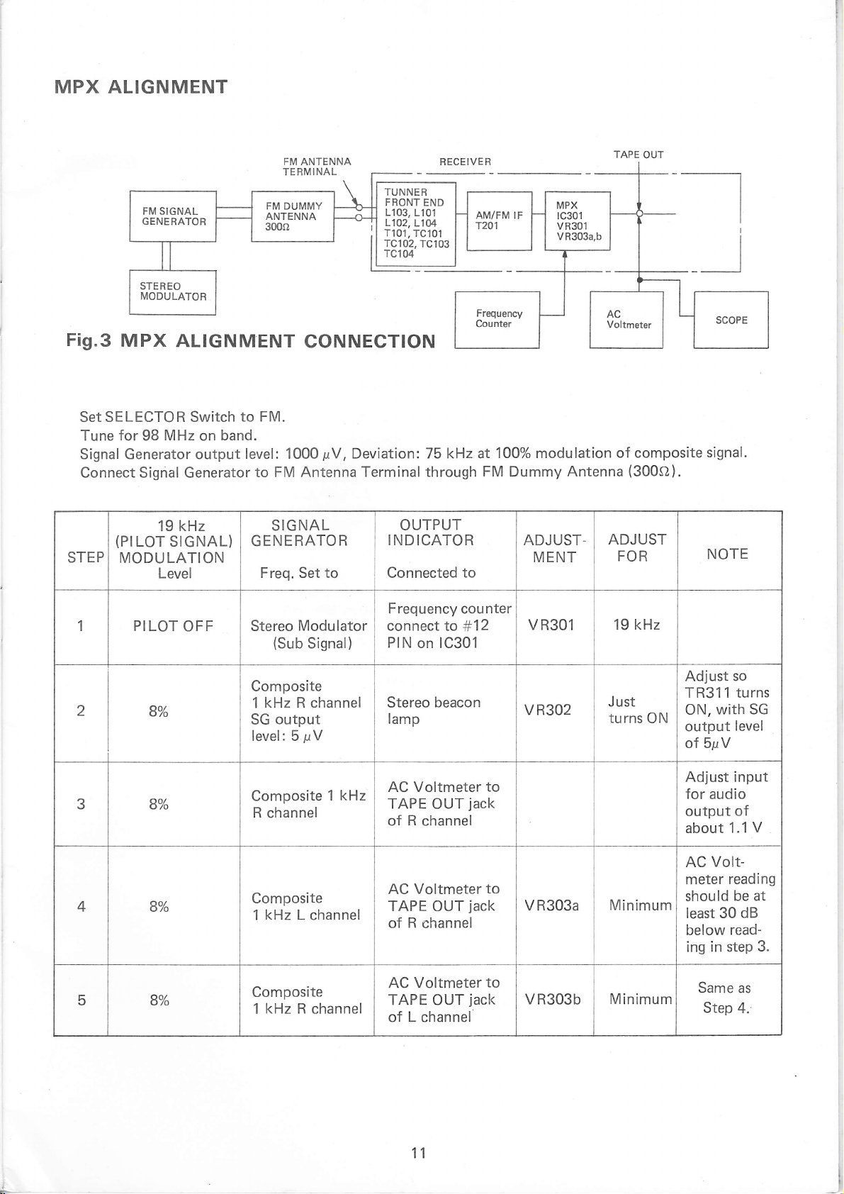
MPX ALIGNMENT
FM SIGNAL
GENE
RATOR
Fis.3
MPx
SELECTOR Switch
Set
for
Tune
ALIGNMENT
MHz
98
on
Signal Generator output
Connect Signal Generator
kHz
(PILOT
STEP
19
SIGNAL)
MODULATION
Level
FM DUMMY
ANTENNA
30t)r,
to FM.
band.
level: 1000
to FM Antenna
SIGNAL
GENERATOR
Freq. Set to
FM ANTENNA
TERMINAL
CONNECTION
pV,
Deviation:
Terminal
RECEIVER
TUNNER
FRONT
END
1103,1101
L102,
L104
T101,
TC101
TC102,
TC103
TC104
75 k{z at
through
OUTPUT
INDICATOR
Connected
1OO% modulation
FM Dummy Antenna
ADJUST.
MENT
to
TAPE OUT
of composite
(300S2).
ADJUST
FOR
__l
signal.
NOTE
1 PI LOT
2
3 B%
4 8%o
5 8%
Bo/o
OFF
Stereo
Modulator
(Sub
Signal)
Composite
kHz R channel
1
output
SG
level: 5
pV
Composite
R
channel
Composite
kHz
1
L channel
Composite
kHz
1
R channel
1 kHz
Frequency counter
connect to
PIN
on 1C301
Stereo
lamp
AC Voltmeter
TAPE
R
of
Voltmeter
AC
TAPE OUT
of R
Voltmeter
AC
TAPE
beacon
OUT
channel
channel
OUT
#12
to
jack
to
jack
to
jack
of L channel
VR301 19
V R3O2
V R303a
vR303b
Just
turns ON
Minimum
Minimum
kHz
Adjust
so
TR311 turns
with SG
ON,
output
level
of SpV
Adjust input
for
audio
Volt-
Same
Step
of
V
1.1
reading
be at
dB
read-
as
4.
output
about
AC
meter
should
least 30
below
ing in step
3.
11
F
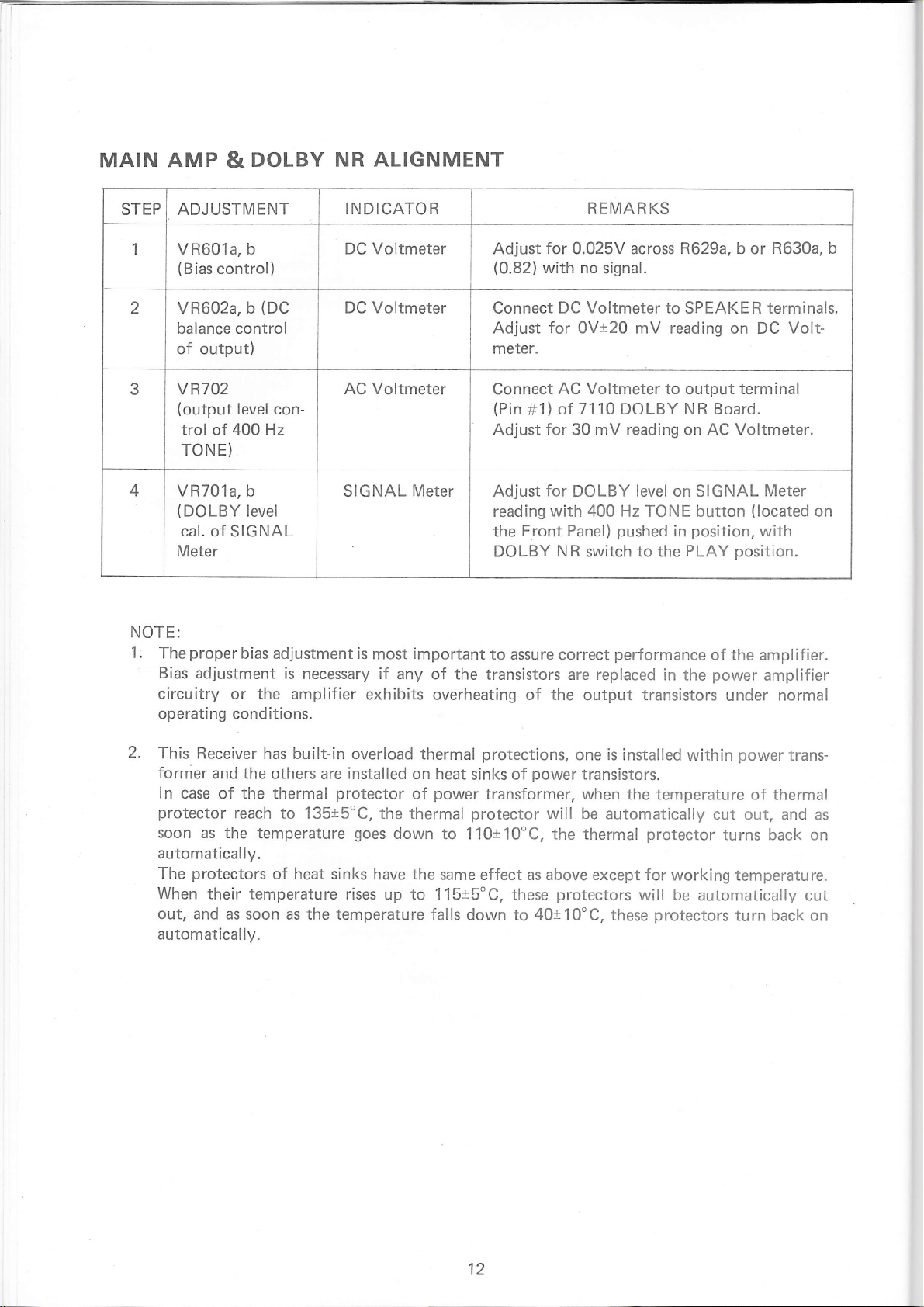
MAIN AMP
DOLBY NR
&
ALIGNMENT
STEP ADJUSTMENT
1 VR601a,
(Bias
2 VR602a, b
balance control
b
control)
(DC
of output)
NOTE:
.
1
The
Bias
'
vR702
(output
trol of
TONE)
(DOLBY
cal. of SIGNAL
Meter
proper
level
400 Hz
b
level
bias
adjustment is
con-
adjustment is
3
4 VR701a,
circuitry or the amplifier
operating conditions.
INDICATOR REMARKS
Voltmeter
DC
DC Voltmeter
Adjust
(0.82)
Connect
for 0.025V across R629a, b or
with no
DC Voltmeter to
Adjust for 0Vt20 mV reading
meter.
AC Voltmeter
SIGNAL Meter
Connect
(Pin
Adjust
Adjust
reading
the
AC Voltmeter to
of
#11
for 30 mV reading on AC Voltmeter.
for
with
Front Panel)
DOLBY NR switch to the
important
most
necessary if
exhibits
any of the
overheating of the
to assu re
transistors are replaced
correct
signal.
SPEAKE R terminals.
on DC Volt-
output
7110
DOLBY
NR Board.
DOLBY level on SIGNAL
400 Hz TONE button
pushed
position,
in
PLAY
performance
in the
output transistors
terminal
position.
of the amplifier.
power
under normal
R630a, b
Meter
(located
with
amplifier
on
2.
This Receiver
fornier
ln
case
protector
soon as the
automatically.
The
When
out, and
automatically.
has built-in
and the
of
the
reach
others are
thermal
protector
to 135t5'C,
temperature
protectors
their temperature
of heat
as soon as the temperature
sinks have the
rises
overload thermal
installed
on heat
power
of
the thermal
goes
down
up
to 110t10'C, the thermal
same effect as above
to
115t5"C,
falls down
protections,
sinks of
transformer, when
protector
these
to
one is installed
power
transistors.
will be
protectors
40t19'9,
the temperature
automatically
protector
except
for
will be
protectors
these
within
power
thermal
of
trans-
cut out, and
turns back on
working temperature.
automatically cut
turn back
on
as
12
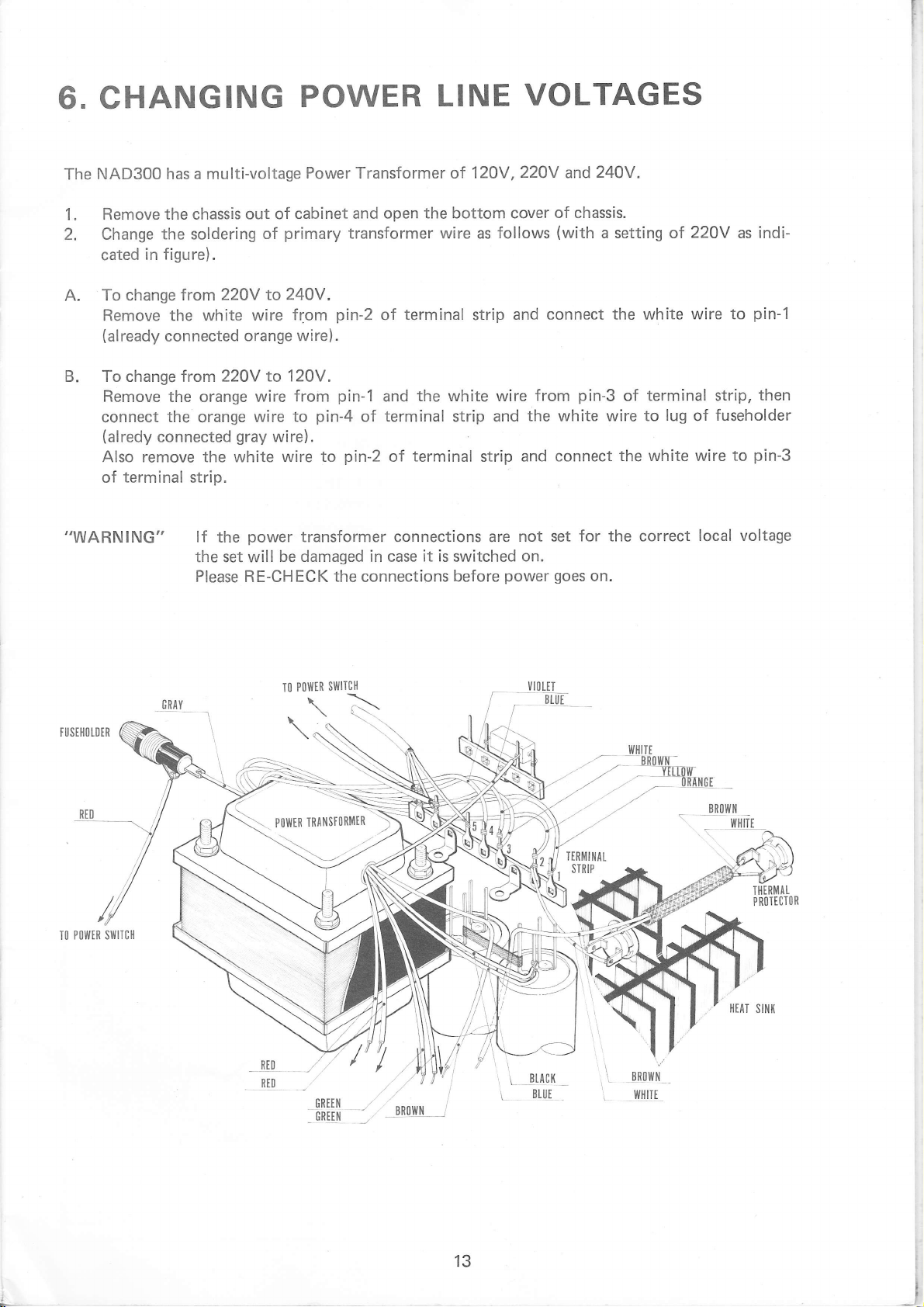
Ci. CHANGING
NAD300 has
The
a multi-voltage
POWER
Power Transformer of 12OV,22OV
LINE
VOLTAGES
and
240V.
Remove the chassis
1.
2.
Change
cated
To change
A,
Remove the
(already
B.
To change trom 22OV
Remove
connect
(alredy
the soldering
in figure).
from22OY
connected
the orange wire
the
connected
Also remove the white
terminal
of
,,WARN
ING"
strip.
out of
cabinet and
primary
of
to24OV.
white wire
orange wire).
from
to 120V.
from
to
orange
wire
gray
wire).
wire to
the
power
transformer connections are
be damaged in case
lf
the set will
Please RE-CHECK
open the bottom cover
transformer wire as
pin-2
pin-1
pin-4
pin-2
the
terminal
of
the white wire
and
terminal
of
terminal
of
connections
strip and
it is
switched
strip
strip
before
of chassis.
follows
(with
connect the white
and
from
the
and connect
set for the correct
not
on.
power
goes
pin-3
white
on.
a setting of
terminal strip,
of
wire to
lug
the white wire
22OV
wire to
of
local voltage
indi-
as
pin-1
then
fuseholder
pin-3
to
TUSIllOTDER
POlllER SI{ITIH
TO
swllc}l
P0wiR
I0
\.\
t{t{tTE
BR0[4I
.-' _ T[Inr
''"
///
ng4[0l
7
.
tow,*tRltsroRilrR
\
..7
,,'
---:-
\
\---7
//
'P
///
,
1
_.G
REt N
GRILil
,.
tR0lltx_i
L
-ILACK
Btljt
\
\
13
_l
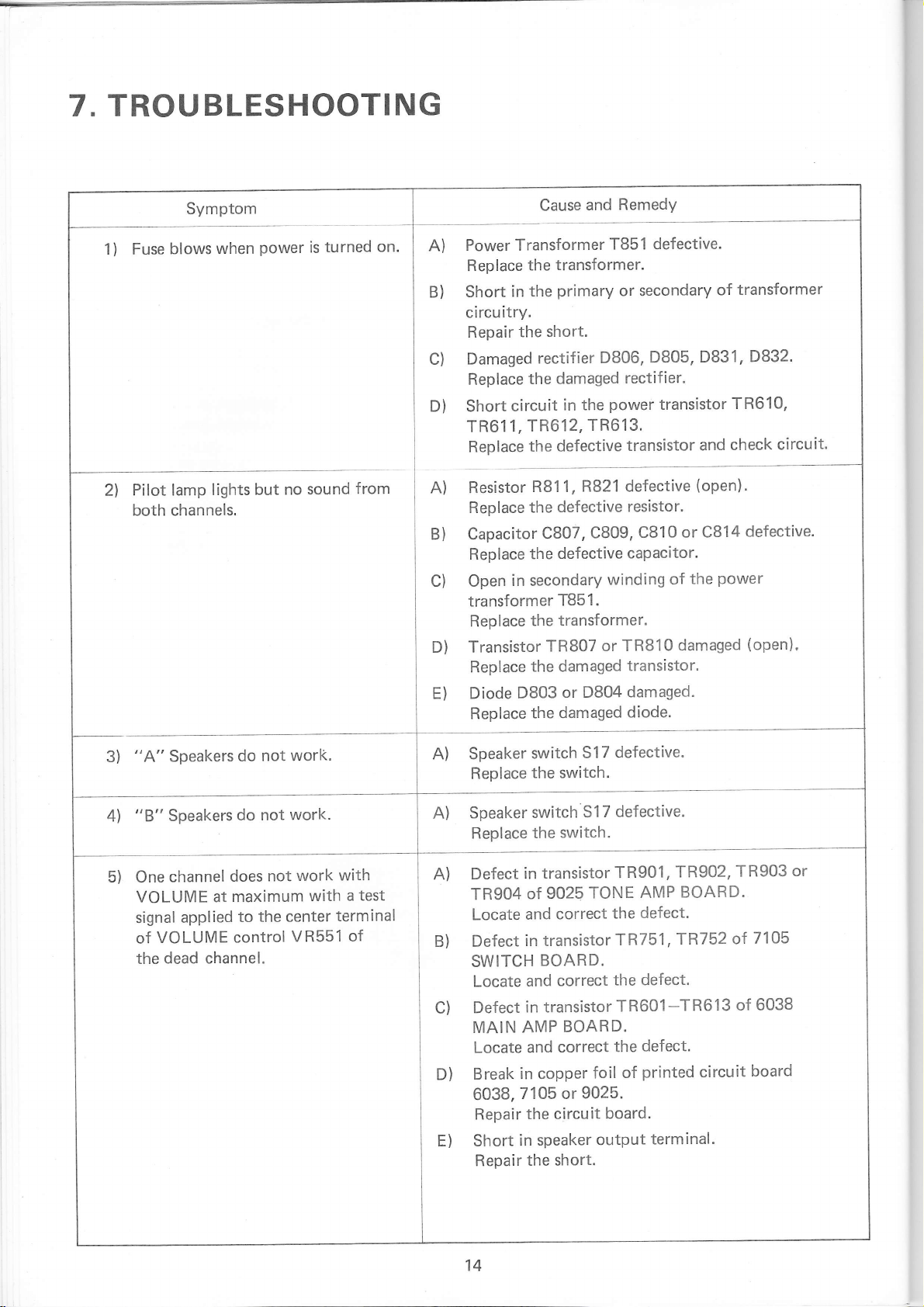
T,TROUBLESHOOTING
Symptom
Fuse
1)
Pilot lamp
2l
both channels.
blows when
lights
power
but no
turned on.
is
sound
from
Power Transformer
A)
lace
R ep
--
B)
Short
in
circuitry.
the short.
circuit
,TR612,
in secondary
c)
D)
A)
B)
c)
Repair
Damaged
Replace
Short
TR611
Replace
Resistor
Replace
Capacitor
Replace
Open
transformer
Replace
Transistor
D)
Replace
E)
Diode
D803
Replace
T851 defective.
transformer.
the
primary
the
rectifier
the damaged
in
or secondary
D806,
rectifier.
power
the
TR613.
the defective
R811,
defective
the
C807,
defective
the
transistor
R821 defective
resistor.
C809,
capacitor.
winding
T851.
the transformer.
TR807
the damaged
the damaged
or TR810
or D804
transistor.
damaged.
diode.
D805,
transistor
C810
of
of
D831,
TR610,
check
and
(open).
or CB14
power
the
damaged
transformer
D832.
circuit.
defective.
(open),
3)
4l
5)
"A"
"B"
Speakers
Speakers
channel
One
VOLUME
applied
signal
VOLUME control
of
dead channel.
the
does
at maximum
not worl(.
do
do not
not
the center
to
work.
work
with
VR551
with
test
a
terminal
of
A) Speaker
Replace
Speaker
A)
Replace
Defect
A)
TR904
Locate
Defect
B)
SWITCH
Locate
Defect
c)
MAIN
Locate
Break
D)
6038,
Repair
Short
E)
Repair
switch
S17
the switch,
switch
the
in
of
and
in transistor
S17
switch.
transistor
TONE
9025
correct
BOARD.
correct
and
in transistor
BOARD.
AMP
correct
and
in copper
9025.
or
7105
the circuit
speaker
in
the short.
defective.
defective.
TR901,
AMP
defect.
the
TR751
,1R752
the defect.
TR601-TR613
defect.
the
printed
of
foil
board.
output
terminal.
TR902,
BOARD.
circuit
TR903
7105
of
of 6038
board
or
14
 Loading...