


800235-0A
User's Manual
High Speed Digital Camera System
GX-3
Model MC-529
JAN 2010
nac Image Technology, Inc.

(00235)

(00235)
- 1 -
Introduction
The MEMRECAM GX-3 is designed to analyze images moving at speeds not
visible to the naked eye.
The MEMRECAM GX-3 has a unitized configuration with an IC memory as the
storage medium and so is a high speed digital camera that possesses the
identical compact nature of a high speed film camera, the same immediate
playback function of a high speed video camera, and can handle the digital
data from all of the images after recording.
The MEMRECAM GX-3 easily performs the high speed photography
necessary for high speed techniques. Photography and analysis without the
use of a computer is possible with the included software containing the
functions of remote operation from a computer with the simple operation of the
included remote controller, image storage to a USB compatible external
storage medium using the USB port and live image display using the
viewfinder or monitor.
The MEMRECAM GX-3 is designed for high speed and superior image quality
requirements. Photography at a resolution of 1280 x 1024 pixels is possible
with a photographic speed of 1,500 frames per second. High speed
photography is possible up to 198,000 frames per second (4(H) x 16(V)) using
a split frame. Also, high speed image transmissi on to the cont rol computer can
be performed according to the high speed network (10BASE-T, 100BASE-TX,
1000BASE-T).
The MEMRECAM GX-3 performs high speed photography in demanding test
environments, as well as possessing properties resistant to magnetism.
This user's manual provides the specifications, operating methods, interface
with peripheral equipment and system expandability information to use the
MEMRECAM GX-3 with these features.
Trademark
MEMRECAM is a registered trademark of nac Image Technologies, Inc.

(00235)
- 2 -
(Blank page)

(00235)
- 3 -
Read Before Using
Safety Precautions
To ensure safe use of this device, please completely read all of these following precautions before use.
When using this device, the following symbols and warnings are displayed for areas where particular
caution is necessary for safety. If there is a safety alert symbol within the description, please read the
warning carefully before beginning operation. There may be unexpected problems due to conditions and
circumstances of use of the device that are not listed below. Please carefully read all of the user's manual
for the device. Directly contact the retail outlet if there are questions about this device.
DANGER
This indicates the existence of an imminently dangerous situation that could result in death or
serious bodily injury to the user if the precaution is not observed.
WARNING
This indicates the existence of a potentially dangerous situation that could result in death or
serious bodily injury to the user if the precaution is not observed.
CAUTION
This indicates the existence of a potentially dangerous situation that could result in slight
bodily injury or moderate damage to the user if the precaution is not observed. This warning
sign indicates a warning relating to faulty operation and the existence of areas where there is
concern of damage to this device or connected devices.

(00235)
- 4 -
Handling Precautions
Safety alert symbol
This is a「Safety Alert Symbol」.
This symbol is intended to alert the user of items or operations that could be
dangerous to oneself or others during the use of this device. Carefully read the
messages accompanying this symbol and follow the instructions to safely use this
device.
Grounding terminal symbol
This symbol is displayed in areas with grounding terminals. If not ground ed, electrical
shock may occur when metal or other parts of the device are contacted. Do not
ground, due to the dangers involved.
If a 3P-2P conversion plug is used to connect to the power outlet, connect the
grounding wire of the conversion plug to the grounding terminal.
High voltage warning symbol
This symbol is displayed in areas of dangerously high voltage.
Remove the power cable from the outlet when replacing fuses.
Do not remove the cover of this device. Electrical shock could occur if this device is
handled with the cover removed even if the power switch is OFF.
High temperature caution symbol
This symbol is displayed in areas of dangerously high temperature.
The device generates the heat and may become high temperature under energizing.
Don't touch the device as much as possible while operating. There is the danger of
the burn.

(00235)
- 5 -
Precautions for Use
Caution
Verify Power Input
Power input to the system should be AC 100~240V/47~63Hz when using the AC adapter
(option), and DC20~32V when using DC power or batteries. Please verify power voltage,
frequency and polarity prior to connecting to power.
Caution Operating Environment
・Use in locations where the ambient temperature is 0~+40°C and the RH is 30~80%. Use
where there is no condensation.
・Store wher e the ambient temperature is -10~+60°C and the RH is 20~80%. S t ore where
there is no condensation.
・Avoid using in locations with smoke, corrosive gases or strong m agnetism.
・Do not store in locations subject to direct sunlight, rain or salt water.
・Do not use in locations with excessive dirt, dust, sand or moisture.
Caution Vibration and Shock
In MEMRECAM GX-3, there are no vibration and shock resistant properties requested by
the collision experiment etc.
Please examine GX-1 etc. about use in such an environment.

(00235)
- 6 -
Caution Handling the Main Camera Unit
The inside of the main camera unit contains parts that are precisely manufactured and
installed. Please keep the screws in the camera cover tightened and do not open the
cover under any circumstances (even if the main camera unit do es not operate properly).
It may not be possible to recover the functions of the camera.
Caution Generation of Heat
Heat will be generated during operation of the system but it will not interfere with operation.
If an abnormal amount of heat is generated, turn off the power and unplug from the outlet.
Directly contact the retail outlet or this company.
Caution Handling the Lens Mount
Remove the lens or cap on the lens mount of the camera to view the camera contents. Do
not touch or place items inside. This could damage the optical system, and any dust could
adversely affect the image.
Warning Handling Cables
Turn the power off while connecting or removing cables.
With the power still on, connecting or removing cables could result in a malfunction, or
electrical shock.
Do not put metal parts into the connecto rs.
Caution Handling the Battery
The MEMRECAM GX-3 is equipped with a standard memory backup battery so does not
place in direct sunlight in vehicles, near fire, on the stove or any location with high
temperatures.
The battery could leak and adversely affect performance of the battery of its life.
Do not use the memory backup batteries for any other purpose. The battery could leak,
generate heat or malfunction.
Contact a retail outlet for replacement memory backup batteries.
Caution Handling When Moving or Transporting
Use the special carrying case for this product when moving or transporting.

(00235)
- 7 -
Caution Amplification of Sensor Noise
The temperature of the image sensor used in this product alters the screen noise. This
noise has a pattern that differs from the stationery pattern noise for each sensor.
In this product, noise reduction is performed by correcting the temperature changes as
well as the stationary pattern noise for the sensor.
If a finer image quality is desired, adjust the black balance immediately prior to
photographing.
Depending on the conditions and circumstances of use of the device, there may be malfunctions
other than those listed above. Please carefully read all of the user's manual for the device. Directly
contact the retail outlet if there are questions about this device.
Parts to be Replaced on a Regular Basis
・Clock Battery
The clock battery will last for approximately 8 years. Replacement cannot be made by the user so
please contact the retail outlet or this company.
・Memory Backup Battery
Please replace the memory backup battery approximately one year after purchase. If the discharge
rate accelerates or if there are differences in amount of use, please repla ce immediately. Replacement
cannot be made by the user so please contact the retail outlet or this company.
Warranty
The warranty period for the MEMRECAM GX-3 is for one year after delivery.
For details, refer to the attached warranty.

(00235)
- 8 -
(Blank page)

(00235)
i
Table of Contents
Introduction ······················································································ -1Read Before Using ·········································································· -3Precautions for Use ········································································· -5Parts to be Replaced on a Regular Basis ········································ -7Warranty ·························································································· -7-
1.Overview
1.1 Standard Components ···································································· 1‐2
1.2 The Exterior of the MEMRECAM GX-3 & The Names and Functions
of Each Part ···················································································· 1‐3
1.2.1 Front Panel ············································································ 1‐4
1.2.1 Lens Mount ············································································ 1‐5
1.2.2 Rear Panel ·············································································· 1‐6
1.3 J3 Simplified I/O Cables
(option) ···················································· 1‐9
1.4 AC Adapter
(option) ······································································· 1‐10
1.5 GX Link
(option) ············································································· 1‐11
2.Basic Operation
2.1 The Flow of Operations ·································································· 2‐2
2.2 Preparation s ··················································································· 2‐3
2.3 Power ····························································································· 2‐4
2.3.1 MEMRECAM GX-3 Startup ····················································· 2‐4
2.3.2 Remote Control J-PAD3 St artup ·············································· 2‐6
2.4 Stop (STOP Mode) ········································································· 2‐7
2.5 Live Image Display (VIEW Mode) ··················································· 2‐8
2.6 Recording ······················································································· 2‐9
2.6.1 ARM Mode ·············································································· 2‐10
2.6.2 REC Mode ··············································································· 2‐11
2.7 Memory Backup ·············································································· 2‐12
2.8 Playback ························································································· 2‐13
2.8.1 Single Frame Playback (PLAY Mode) ······································ 2‐15
2.8.2 Loop Playback (LOOP Mode) ·················································· 2‐16
2.8.3 Playback at Varying Speeds ···················································· 2‐17
2.8.4 Skip Forward, Fast Forward, Rewind ······································ 2‐18
2.8.5 Frame Jumping ······································································· 2‐19
2.8.6 Playback Range Settings ························································ 2‐20
2.9 Save to USB compatible storage media ········································ 2‐22

(00235)
ii
3.Recording and Playback Settings
3.1 Items That Can Be Set ··································································· 3‐2
3.1.1 TOP MENU Settin g s ································································ 3‐2
3.1.2 SYS MENU Settings ································································ 3‐3
3.1.3 VIEW MENU Settings ······························································ 3‐4
3.2 Recording Settings ········································································· 3‐5
3.2.1 Trigger Timing Selection (TRIGGER) ······································ 3‐5
3.2.1.1 Start Trigger ································································ 3‐6
3.2.1.2 Center Trigger ····························································· 3‐6
3.2.1.3 End Trigger ································································· 3‐6
3.2.1.4 Custom Trigger ··························································· 3‐7
3.2.2 Recording Speed Selection (FRM RATE) ································ 3‐8
3.2.3 Frame Size Selection (FRM SIZE) ·········································· 3‐9
3.2.4 Custom Settings for Recording Speed and Frame Size
(CUSTOM F) ··········································································· 3‐10
3.2.5 Shutter Exposure Time Selection (SHUTTER) ························ 3‐11
3.2.6 Area Of Interest(AOI) ······························································· 3‐12
3.2.7 Image Trigger (IMG TRIG) Setting ··········································· 3‐13
3.2.8 Automatic Exposure (AE) Control Settings ···························· 3‐15
3.2.9 DRES Mode Settings (DRES) ················································· 3‐15
3.2.10 Recording Bit Length Settings (DEPTH) ································ 3‐16
3.2.11 Initial Value Settings for the Recorded Scene Number
(SCENE) ················································································ 3‐16
3.2.12 Memory Segment Settings (SEG SIZE) ································· 3‐17
3.2.13 External Trigger Signal Selection (TRIG SEL) ······················· 3‐18
3.2.13.1 External Trigger Signals from TRIG1 ························ 3‐18
3.2.13.2 External Trigger Signals from TRIG2 ························ 3‐18
3.2.13.3 Filter Value ································································ 3‐18
3.2.14 Recording Method Selection (REC MODE) ··························· 3‐19
3.2.14.1 AUTO Mode ······························································ 3‐19
3.2.14.2 LOOP Mode ······························································ 3‐20
3.2.14.3 Setting Method ·························································· 3‐20
3.2.14.4 Normal Recording ····················································· 3
‐21
3.2.14.5 Burst Recording ························································ 3‐24
3.2.14.6 Multi Trigger Record ing ············································· 3‐28
3.2.14.7 Event Recording ······················································· 3‐33
3.2.15 Synchronized Timing Selection (SYNC TIME) ······················· 3‐38
3.2.15.1 Setting Method ·························································· 3‐38
3.2.15.2 IRIG Synchronized T ime ··········································· 3‐38
3.2.16 Synchronized Signal Selection (SYNC SEL) ························· 3‐39

(00235)
iii
3.2.16.1 Setting Method ·························································· 3‐39
3.2.16.2 Synchronized EST Signal Recording ························ 3‐39
3.2.17 Sync signal setting at VIEW mode (EST VIEW) ···················· 3‐41
3.2.18 External Input/Output Signal Polarity Selection (SIG SET) ···· 3‐42
3.2.18.1 External Input/Output Signal Polarity Selection ········· 3‐42
3.2.18.2 TRIGER Filter Setting (TRIGFL) ··························· 3‐43
3.2.18.3 EST Filter setting (EST FLT) ····································· 3‐44
3.2.19 Time Stamp Recording (TIMSTAMP) ····································· 3‐45
3.2.20 Exposure Timing Selection (EXP TIME) ································ 3‐46
3.3 Live Image / Playback Image Settings ············································ 3‐47
3.3.1 Gain (GAIN) ······································································· 3‐47
3.3.2 Enhance (ENHANCE) ····························································· 3‐48
3.3.3 Gamma (GAMMA) ··································································· 3‐49
3.3.4 Chroma (CHROMA) ································································ 3‐50
3.3.5 Knee (KNEE) ··········································································· 3‐51
3.3.6 RGB Matrix (RGB COR.) ························································· 3‐52
3.3.7 Luminance (LUMINANC) ························································· 3‐53
3.3.8 Black Balance (BLK BAL) ························································ 3‐54
3.3.9 White Balance (WHT BAL) ······················································ 3‐55
3.3.10 Zoom Image (ZOOM) ···························································· 3‐56
3.3.11 Scroll Image (SCROLL) ························································· 3‐57
3.3.12 Low Light Mode Settings (LOWLIGHT) ································· 3‐58
3.3.13 Playback Memory Segment Selection (ME M SEG) ··············· 3‐59
4.Save Settings
4.1 Items That Can Be Set ··································································· 4‐2
4.1.1 SAVE MENU Settings ······························································ 4‐2
4.2 Save Settings ················································································· 4‐3
4.2.1 Save Frame Range Settings (SAVE FRM) ······························ 4‐3
4.2.2 Save Method Settings (SAVE SET) ········································· 4‐4
4.2.3 Saving Video Files (MCFF)······················································ 4 ‐5
4.2.4 Saving Still Image Files (YC TIFF) ··········································· 4‐5
5.System Settings
5.1 Items That Can Be Set ··································································· 5‐2
5.1.1 TOP MENU Settin g s ································································ 5‐2
5.1.2 SYS MENU Settings ································································ 5‐3
5.1.3 SYSTEM SETUP MENU Set tings ··········································· 5‐5
5.2 System Settings ·············································································· 5‐6
5.2.1 Allowed/Prohibited Settings for Operations on the Control PC
(LOCK) ···················································································· 5‐6

(00235)
iv
5.2.2 ID Number Settings (ID) ·························································· 5‐6
5.2.3 Date and Time Settings (DATETIME) ······································ 5‐7
5.2.4 Display/Do Not Display Settings for Information Superimposed
on the Image (OSD DISP) ······················································· 5‐7
5.2.5 Display / hide the superimposed information by the camera mode
(OSD MODE) ········································································ 5‐8
5.2.6 Trigger clock set tings (OSD TIME) ·········································· 5‐8
5.2.7 Setting s to Disk pay/Hide the Center Mark
of the Image (CAFM DIS) ························································ 5‐9
5.2.8 Frame Counter Display Settings (FRM DISP)·························· 5‐10
5.2.9 Selection of the Frame Time Standard (FRM TIME) ················ 5‐11
5.2.10 Flame relative time display setting(REL TIME) ··················· 5‐12
5.2.11 Image Display/Do Not Display Settings (VIDEOOUT) ············ 5‐13
5.2.12 Remote Control Operation Sou nd Settings (BEEP) ··············· 5‐13
5.2.13 Auto View Function Settings (AUTOVIEW) ···························· 5‐14
5.2.14 Display/Do Not Display Warning Settings (WARNING) ·········· 5‐16
5.2.15 System Information Display (INFO) ······································· 5‐17
5.2.16 Network Settings (IP ADDR) ·················································· 5‐17
5.2.17 Reset Settings (RESET) ························································ 5‐18
5.2.18 Video Output Method Selection (VIDEOOUT) ······················· 5‐18
6.Troubleshooting
6.1 Troubleshooti ng ···················································································· 6‐2
6.1.1 The ARM Mode Cannot Be Accessed······································ 6‐2
6.1.2 Trigger Input Does Not Work with the Remote Control
J-PAD3 ···················································································· 6‐2
6.1.3 External Tr igger Input Does Not Work ····································· 6‐3
6.1.4 Recording is completed before putting in a trigger ··················· 6‐3
6.1.5 The EST Signals Ar e Not Synchronized ·································· 6‐3
6.1.6 Not Synchronized with the IRIG Time ······································ 6‐4
6.1.7 Response to System Crashe s ················································· 6‐4
7.Specifications
7.1 Imager ··································································································· 7‐2
7.2 Recorder ······························································································· 7‐6
7.3 Video Converte r ···················································································· 7‐10
7.4 System Controls ···················································································· 7‐11
7.5 Input/Output Connector ········································································· 7‐18
7.6 Environment ·························································································· 7‐21
7.7 Shape ··································································································· 7‐21
7.8 Adaptive Standards ··············································································· 7‐21

(00235)
v
7.9 Accuracy ······························································································· 7‐21
7.10 Replaceable Parts ··············································································· 7‐21
7.11 Exterior Diagram ················································································· 7‐22
APPENDIX A Trigger ··················································································· 7‐23
APPENDIX B Exposure Start Signal (EST) and Event S i gnal ····················· 7‐24
APPENDIX C Exposure Pulse Output (E PO) ·············································· 7‐26
APPENDIX D Discrete Interface ································································· 7 ‐28
APPENDIX E IRIG-B ·················································································· 7‐29
APPENDIX F AUTO PILOT ········································································ 7‐30
8.Options
8.1 Specifications of the Main Options ························································ 8‐2
8.2 Exterior Diagram ··················································································· 8‐5

(00235)
vi
(Blank page)

(00235)
1-1
1
Overview

(00235)
1-2
1.1 Standard Components
The MEMRECAM GX-3 high speed digital camera system consists of the following items as shown in
Table 1-1.
Table 1-1 Standard Configuration
Descriptions Model Quantity
MEMRECAM GX-3 (Figure 1-1)
V-190 1
Conversion cable for viewfinder (Figure 1-2)
584888 1
Figure 1-1 MEMRECAM GX-3
Figure 1-2 Conversion cable for viewfinder

(00235)
1-3
1.2 The Exterior of the MEMRECAM GX-3 & The Names
and Functions of Each Part
The exterior of the MEMRECAM GX-3 is shown below (Figure 1-3, Figure 1-4).
Figure 1-3 The Exterior of the MEMRECAM GX-3 [I] (lens: NIKON 50 ㎜ (sold separately))
Figure 1-4 The Exterior of the MEMRECAM GX-3 [II] (lens: NIKON 50 ㎜ (sold separately))

(00235)
1-4
1.2.1 Front Panel
The front panel of the MEMRECAM GX-3 is shown below (Figure 1-5).
The F mount adapter is secured to the front panel with four screws.
When not using the MEMRECAM GX-3, use the mounting cap and do not leave the mounting
aperture open. Please use caution to avoid letting dirt and dust inside the mount.
Figure 1-5 MEMRECAM GX-3 (Front Panel)
F mount adapter

(00235)
1-5
1.2.2 Lens Mount
The aperture ring is installed in the lens mount in MEMRECAM GX-3.(Figure 1-6)
This aperture ring is used by correspond the following.
Type of F mount lens
Lens without aperture ring Stopping down the lens is adjusted with the mount aperture ring.
However, please adjust it while confirming an actual image because
the index of the mount is a rough guide.
Lens with aperture ring Please turn the mount aperture ring to the conduct oneself that
stops in the direction of CLOSE (The function of the mount aperture
ring is released).
Figure 1-6 MEMRECAM GX-3(Lens Mount)
(lens: SIGMA 24㎜ (sold separately))
CAUTION When it is used by MEMRECAM GX-3, depending on representation resolution,
vignetting may produce some F mount lenses. (Example: Nikon DX Nikkor Lens)
CLOSE
Mount aperture ring
Lens aperture rin
g
OPEN

(00235)
1-6
1.2.2 Rear Panel
The rear panel of the MEMRECAM GX-3 is shown below (Figure 1-7).
Figure 1-7 MEMRECAM GX-3 (Rear Panel)
I/O Connector
Status LED

(00235)
1-7
1) Input/Output Connectors
There are three input/output connectors on the rear panel. Input/output signals and cable connections for
each connector are shown below (Table 1-2).
Table 1-2 Input/Output Signals and Cable Connections
Name of Connector Name of Branch Connector Input/Output Signal
DCIN Power input
J-PAD
RS232C (remote control JPAD3 connection)
DC24V output (JPAD3 power)
TRIG 1 External trigger input (TRIG1)
VF
Video signal output
DC24V output (VF power)
USB USB (USB compatible storage media connection)
J3
(REMOTE)
ID color: Blue
ETHER Ethernet (control PC connection)
TRIG2
(*1)
External trigger input (TRIG2)
EST2
(*1)
Signal input to start exposure / event input (EST2)
IRIG-B
(*1)
IRIG-B time code input
EPO
(*1)
Exposure panel output (EPO)
PWRCNT
(*1)
Power control signal input
(*1) J3 branch cable (option) required.

(00235)
1-8
2) Status LED
There are five status LEDs on the rear panel showing the status of the MEMRECAM GX-3. The color
displayed for each LED and the flashing status changes according to the change in status. (Table 1-3).
Table 1-3 LED Status Display
LED Name Display Color and Flashing Status MEMRECAM GX-3 Status
UB
(USB)
Lit green Bus power supply
Not lit Bus power OFF
ET
(ETHERNET)
Lit green Connected to network
Flashing green Communicati ng with network
Not lit Not connected to network or Power OFF
CM
(CAMERA
MODE)
Lit blue STOP mode
Lit white VIEW mode
flashing white
VIEW mode
(during EST synchronized signal recording)
Lit magenta ARM mode
flashing magenta
ARM mode
(during EST synchronized signal recording)
Lit orange REC mode
flashing orange
REC mode
(during EST synchronized signal recording)
Not lit Power OFF
PW
(POWER)
Lit green Power ON (normal status)
Lit red Power ON (fail status
(*1)
)
Not lit Power OFF
MB
(MEMORY
BACKUP)
(*2
)
Lit green
Valid memory backup, Charge: High
(backing up with external power)
Flashing green
Valid memory backup, Charge: High
(backing up with battery)
Lit orange
Valid memory backup, Charge: Medium
(backing up with external power)
Flashing orange
Valid memory backup, Charge: Medium
(backing up with battery)
Lit red
Valid memory backup, Charge: Low
(backing up with external power)
Flashing red
Valid memory backup, Charge: Low
(backing up with battery)
Not lit No memory backup data
(*1) Fail status: During MEMRECAM GX-3 operation, indicates a malfunction detected, an abnormal
power voltage detected or an increase in the sensor temperature detected.
(*2) The charge amount is impacted by differences in batteries and the ambient temperature, and is not
precisely displayed.
Use only as a guide.
3) Battery Case
There is a memory backup battery in the battery case on the bottom plate. Please refer to
【7.4.4 Memory Backup】 for specifications and use of the battery.

(00235)
1-9
1.3 J3 Simplified I/O Cables (option)
The cable connected to the input/output connectors on the rear panel are shown below. (Figure 1-8). Refer
to【1.2.2 1) Input/Output Connectors】for the input/output signals from the cable branch connecto rs.
Figure 1-8 J3 Simplified I/O Cable
Camera connecto
r
(J3)
Ethernet

(00235)
1-10
1.4 AC Adapter (option)
The exterior of the AC adapter is shown below (Figure 1-9).
A specialized power plug is installed on the output terminal of the AC adapter, which connects to the J1
cable POWER connector. The AC input terminal on the other end is a 3P plug and connects to AC100V
~240V power.
Power ON/OFF for the MEMRECAM GX-3 is performed by the AC adapter power switch.
Figure 1-9 AC Adapter
Due to the danger of high voltage, do not open the cover.
If using a 3P-2P conversion plug to connect to a power outlet, be sure the grounding wire for
the conversion plug is connected to an external ground. If not grounded, electrical shock may
occur from the metal parts or other areas of this unit.
The AC adapter is a specialized part for the MEMRECAM GX-3, and so should not be used
with other devices.
Warning

(00235)
1-11
1.5 GXLink (option)
The control software GXLink is provided on a CD-ROM (Figure 1-10).
Please refer to【GXLink User's Manual】for GXLink details.
Figure 1-10 Control Software GXLink

(00235)
1-12
(Blank page)

(00235)
2-1
2
Basic Operations

(00235)
2-2
2.1 The Flow of Operations
The three methods to operate the MEMRECAM GX-3 are as follows.
Operation using the remote control J-PAD3(OPTION)
Operation using the control software GXLink
Operation using external input/output signals
This user's manual describes operation using the remote control J-PAD3.
The flow of operations for basic recording, playback and storage is shown in Figure 2-1. Settings using
the J-PAD3 are described in Chapters 3, 4 and 5.
Refer to【GXLink User's Manual】for operations using the control software GXLink.
Live Image Display
(VIEW Mode)
Preparations
Power on
Save to USB
compatible storage
media
Power off
(Memory Backup)
(page 2-3 )
(page 2-4~6)
Recording Settings
(Setting of the recording speed, frame size,
shutter exposure time, etc)
(page 2-9~12)
(page 3-17~39)
Recording
(ARM/REC Mode)
Playback
(PLAY Mode)
Stop
(STOP Mode)
Playback Image Settings
(Adjustment of the playback image quality)
(page 2-7)
Stop
(STOP Mode)
Stop
(STOP Mode)
Live Image Settings
(Adjustment of the live image quality)
Save Settings
(Setting of the save frame range, save method,
etc)
(page 2-8)
(page 2-12)
(page 2-13~21) (page 2-22~23)
(page 3-5~16)
(page 3-47~59)
(page 3-47~59)
(page 5-5~18)
(page 4-3~5)
Recording Settings
(Setting of the recording method, memory
segment, synchronized signal, etc)
System Settings
(Setting of the date, superimposed Information
display, etc)
Figure 2-1 The Flow of Operations

(00235)
2-3
2.2 Preparations
Prepare the devices shown in Table 2-1 and connect as shown in Figure 2-2.
Table 2-1 Devices to Prepare
Part Model Notes
MEMRECAM GX-3 V-190 Standard component
F mount lens Option
AC adapter 584182-1 Option
Remote control J-P A D3 CR1011 Option
USB2.0 compatible storage
Option
Conversion cable for viewfinder 584888 Standard component
Viewfinder ZO-971 Option
External triggering input power Option
J3 simplified I/O cable 584260 Option
Control PC Required when using the control software GXLink.
External triggering
input power
Conversion cable
for viewfinder
MEMRECAM GX-3
(REAR VIEW)
ETHERNET
Viewfinder
J-PAD3
AC adapter
Control PC
※Required when
using the control
software GXLink.
USB2.0 compatible
storage media
※Required when saving the
recorded image.
Figure 2-2 Connections for Each Device

(00235)
2-4
2.3 Power
After connecting each device, turn the power on for the MEMRECAM GX-3 by plugging in the AC adapter
power switch. There is no power switch for the main MEMRECAM GX-3 unit. Once the MEMRECAM GX-3
starts up, it enters the STOP mode.
2.3.1 MEMRECAM GX-3 Startup
■ Viewfinder Image Display
1) Turn on the AC adapter power switch to power the
MEMRECAM GX-3.
2) Press the viewfinder power switch to display the initial
screen (Figure 2-3).
3) After a few moments, it will switch to the system information
screen (Figure 2-4).
The yellow gauge in the center shows the status of the
automatic camera diagnostics.
図 2-3 初期画面

(00235)
2-5
4) After the automatic diagnostics have been completed, the test image recorded during automatic
diagnostics is displayed and the MEMRECAM GX-3 enters the STOP mode. Nine areas of information
are superimposed at the top and bottom of the screen (Figure 2-5).
①Scene number ②Trigger timing ③Trigger time ④Frame counter
⑤Memory segment
number
⑥Camera mode ⑦Playback speed ⑨Shutter exposure
time
⑧Recording speed
Fi
g
ure 2-5 STOP mode screen

(00235)
2-6
■ Main Unit Rear Panel LED Display
1) After turning on the power to the MEMRECAM GX-3, the main unit rear panel LED will display that
shown in Figure 2-6 ① and ② until the automatic diagnostics have been completed.
2) Once the MEMRECAM GX-3 starts up normally and enters the STOP mode, the main until rear panel
LED will display that shown in Figure 2-6 ③.
Figure 2-6 The Main Unit Rear Panel LED Display at St artup
2.3.2 Remote Control J-PAD3 Startup
1) After the MEMRECAM GX-1 power has been turned on, power is
supplied to the remote control J-PAD3. There is no power switch
on the J-PAD3 unit.
The version information screen is shown on the J-PAD3 LCD
display. (Figure2-7)
2) After a few moments, it will switch to the status screen for the STOP mode and the 11 statuses are
displayed. (Figure 2-8).
①Camera mode
②Frame counter
③Frame time
④Playback speed
⑤Recording speed
⑥Frame size
⑦Shutter exposure time
⑧Trigger timing
⑨ID number
⑩Scene number
⑪Playback range bar
Figure 2-7 J-PAD3 version information screen
Figure 2-8 Status Screen (STOP mode)

(00235)
2-7
2.4 Stop (STOP Mode)
■
Switching to the STOP Mode
Press STOP
.
MEMRECAM GX-3 normally starts up in the STOP mode. If operating in any mode other than STOP,
press J-PAD3 STOP
to stop operation and access the STOP mode.
Settings relating to recording conditions, playback conditions and storage are p erformed in the STOP mode.
Refer to
【
3 Recording and Playback Settings
】
and
【
4 Save Settings
】
for these settings.
■
Image Display
The test recorded image is displayed during the
automatic diagnostics at startup. Information is
superimposed at the bottom and top of the screen
and the camera mode (Status) is displayed as
"STOP" (Figure 2-9). At this point, the memory is
empty and the superimposed information indicates
"*" for the image.
The memory segment number (SEG) and the
playback speed (PLAY) are shown regardless of the
presence of recording memory.
The superimposed information displayed in blue is
information relating to the image saved in the
memory or playback information
Caution)In the starting at the time of backup by a Batt ery, the already recorded image (image at the time
of the last operation) is displayed.
■
J-PAD3 Display
The status screen is shown in Figure 2-10, and
the camera mode "STOP" is displayed. At startup, if
the memory is empty , the factory settings are sho wn
on the status screen.
The "TIME" cannot be determined until recording
has ended, so "*" is shown.
The playback range bar is shown empty.
■ Rear Panel LED Display
During the STOP mode,the CM LED is lit up in blue.
Fi
g
ure 2-10 J-PAD3 Display (STOP Mode
)Fig
ure 2-9 Image Display (STOP Mode
)

(00235)
2-8
2.5 Live Image Display (VIEW Mode)
■
Switching to VIEW mode
Press VIEW/ARM
.
In the STOP mode, access the VIEW mode each time J-PAD3 VIEW/ARM
is pressed.
Set the recording conditions in the VIEW mode. Refer to
【
3 Recording and Playback Settings
】
for the
settings for recording conditions.
■
Image Display
In the VIEW mode, the image photographed is
displayed live. The superimposed information is
displayed at the top and bottom of the screen, and
the camera mode (STATUS) is shown as "VIEW"
(Figure 2-11).
The superimposed information shown in red is the
current recording conditions. If the recording
conditions are changed, the live image and the
superimposed information are also changed.
Trigger time or the present time recorded on the
image to record is displayed on a trigger (Trigger).
Refer to
【
5.2.6 OSD TIME
】
for setting for OSD
conditions.
The time of image trigger selection, it is displayed on
trigger (Trigger) as Image Trigger, and the background
of an information display of OSD becomes blue
(Figure 2-12).
■
J-PAD3 Display
The status screen is shown in Figure 2-13, and
the camera mode "VIEW" is displayed. The current
recording conditions are shown on the status screen
during VIEW. If the recording conditions are
changed, status screen is also changed.
The status screen information for the frame
counter (Frame) and the frame time (Time) remain
unchanged from that of the STOP mode.
■
Rear Panel LED Display
During the STOP mode,the CM LED is lit up in white.
Fi
g
ure 2-11 Image Display (VIEW Mode
)Fig
ure 2-13 J-PAD3 Display (VIEW Mode
)
Figure 2-12 Image Display (VIEW Mode)
Image trigger selection

(00235)
2-9
2.6 Recording
The MEMRECAM GX-3 memory is comprised of a ring buffer (a circular memory ) where the first recorded
image and the last recorded image are connected for saving. Recording starts with a photographed image
which is sequentially saved in the ring buffer (memory). After the ring buffer completes one cycle, the
subsequent new image is written over. This state continues until recording trigger signals are input.
If recording triggers include the following three kinds of triggers and one of recording triggers is detected, I
will record the number of recording flames set up by 【3.2.1 Selection of recording timing】, and will end
recording.
・J-PAD3 and the trigger command from reactor-control software
・Input thje external trigger signal (TRIG 1 line connector of a rear panel, TRIG 2 line connector of J3
cable)
・Image trigger (Refer to【3.2.7 image trigger function】)
Switch to the camera mode for recording. Use the remote control J-PAD3 to switch to the camera mode
(Figure 2-14).
Figure 2-13 Summary of Operations with the J-PAD3

(00235)
2-10
2.6.1 ARM Mode
Caution)Before Switching to the ARM Mode
Images saved in the memory will be erased when new images are saved over them by switching
to the ARM mode. Switch to the ARM mode after verifying if the images are to be erased.
Save images needed in a USB compatible storage media or in a control PC. Refer to either
【
2.9 Saving
】or【
GXLink User's Manual
】
for the method to save images.
■
Switching to the ARM Mode
Press VIEW/ARM
.
In the VIEW mode, access the ARM mode each time J-PAD3 VIEW/ARM
is pressed, and start
recording.
The recording conditions may not be changed until recording stops.
■ Image Display
In the ARM mode, the image photographed is
displayed live. The superimposed information is
displayed at the top and bottom of the screen, and
the camera mode (STATUS) is shown as "ARM"
(Figure 2-14).
Once recording starts, all of the superimposed
information is shown in red.
After trigger input, the number of saved frames is
displayed in the frame counter (Frame) according to
the trigger timing (Trigger). Refer to 【3.2.1 Trigger
Timing Selection】for trigger timing.
With Trigger, "*" is displayed until recording has
ended.
■J-PAD3 Display
The status screen is shown in Figure 2-15, and
the camera mode "ARM" is displayed. The
established recording conditions are shown in the
ARM mode status screen.
The frame "TIME" cannot be determined until
recording has ended, so "*" is shown.
"0" is shown in the frame counter (FRAME) until
recording has ended.
■Rear Panel LED Display
During the STOP mode,the CM LED is lit up in magenta.
Fi
g
ure 2-15 Image Display (ARM Mode
)
Figure 2-16 J-PAD3 Display (ARM

(00235)
2-11
2.6.2 REC Mode
■
Switching to REC Mode
Press TRIG
. Or, input the external trigger signal.
In the ARM mode, access the REC mode each time J-PAD3 TRIG
is pressed or when an external
trigger signal is input from TRIG 1 line connector of a rear panel. Refer to
【
3.2.12 External Tr igger Signal
Selection
】
for external trigger input.
Once into the REC mode, recording ends according to the set trigger timing. Refer to
【
3.2.1 Trigger
Timing Selection
】
for trigger timing.
Once recording stops, it switches to the STOP mode.
。
■ Image Display
In the REC mode, the image photographed is
displayed live. The superimposed information is
displayed at the top and bottom of the screen, and
the camera mode (STATUS) is shown as "REC"
(Figure 2-17).
After trigger input, the value for the frame counter
(Frame) is lowered for each recorded frame saved.
With Trigger, "*" is displayed until recording has
ended.
■J-PAD-3 Display
The status screen is shown in Figure 2-17, and
the camera mode "REC" is displayed. The
established recording conditions are shown in the
REC mode status screen.
The frame "TIME" cannot be determined until
recording has ended, so "*" is shown.
"0" is shown in the frame counter (FRAME) until
recording has ended.
■Rear Panel LED Display
During the STOP mode,the CM LED is lit up in orange.
。
Fi
g
ure 2-17 Image Display (REC Mode
)
Figure 2-18 J-P A D3 Di splay (REC Mode
)

(00235)
2-12
2.7 Memory Backup
Once recording stops, it automatically switches from the REC mode to the STOP mode. At the same
time, the memory backup function activates (Figure 2-19). The memory backup status can be verified by the
rear panel LED display (Table 2-2). Therefore, even if the external power is cut off, the images saved in the
memory using the battery can be retained (Figure 2-20).
Figure 2-19 Memory Backup with external Power
Figure 2-20 Memory Backup with Battery Power
Table 2-2 Memory Backup Status Display with MB LED
MB LED
(Memory Backup)
Lit green
Valid memory backup, Charge: High
(backing up with external power)
Flashing green
Valid memory backup, Charge: High
(backing up with battery)
Lit orange
Valid memory backup, Charge: Medium
(backing up with external power)
Flashing orange
Valid memory backup, Charge: Medium
(backing up with battery)
Lit red
Valid memory backup, Charge: Low
(backing up with external power)
Flashing red
Valid memory backup, Charge: Low
(backing up with battery)
Not lit No memory backup data
CAUTION) ● The charge amount is impacted by differences in batteries and the ambient temperature,
and is not precisely displayed. Use only as a guide.
● If the LED color turns from flashing orange to flashing red during battery backup, charge
the battery as soon as possible. Turning on the external power (e.g. AC adapter) to the
MEMRECAM GX-3, battery charge starts. If used as is, the excess charge protective
function will be activated and the images in the memory will be lost.

(00235)
2-13
2.8 Playback
Images recorded can be played back as follows.
Single frame playback(PLAY Mode)
Loop playback(LOOP Mode)
Playback at varying speeds
Skip forward, fast forward, rewind
Frame jumping
Set playback range
For the single frame playback, loop playback and playback at varying speeds, a summary of the J-PAD3
key operation follows (Figure 2-21, 22).
PLAY mode
LOOP mode
Change the
playback speed
Continually press
STOP mode
Change the
playback speed
Figure 2-21 Single Frame Playback, Loop Playback and Playback
at Varying Speeds with the J-PAD3
Figure 2-22 Single Frame Playback, Loop Playback and Playback
at Varying Speeds with the J-PA D3 (using the dial)

(00235)
2-14
Fig. 2-23 Dial key operation of J-PAD3

(00235)
2-15
2.8.1 Single Frame Playback (PLAY Mode)
■
Single Frame Playback Method
Press PLAY
. Or press the dial
(
)
.
During the STOP mode, press J-PAD3 PLAY or press the dial ( ) to access the PLAY mode
(Figure 2-20, 21). Recorded images are played back in single frames. With single frame playback, the set
playback range is only played back one time.
To stop single frame playback, play until the final frame or press STOP .
■ Image Display
In the PLAY mode, the recorded image is played
back by single frames. Information is superimposed
at the bottom and top of the screen and the camera
mode (Status) is displayed as "PLAY" (Figure 2-24).
The frame number for the image played back is
displayed on the frame counter (Frame).
■ J-PAD3 Display
The status screen is shown in Figure 2-23, and
the camera mode "PLAY" is displayed. The
recording conditions for photographing are shown
on the status screen during the PLAY mode.
The frame number for the image played back is
shown in the frame counter (FRAME).
The recording time for the image played back is
shown in the frame time (TIME).
There will be a mark showing the current
playback frame position on the playback range bar.
This mark will move to the last frame position and
then the single frame playback will stop.
Frame 2-24 Ima
g
e Display (PLAY Mode
)
Frame 2-25 J-PAD3 Display (PLAY Mode)
Current playback
frame position
Last frame
position
1st frame
position

(00235)
2-16
2.8.2 Loop Playback (LOOP Mode)
■
Loop Playback Method
Continually press PLAY
. Or press PLAY twice.
During the STOP mode, continually press PLAY
or press PLAY again during the PLAY mode to
access the LOOP mode (Figure 2-27, 28). Recorded images are played back in a loop. With loop playback,
the set playback range is played back repeatedly.
To stop loop playback, press STOP
or press the dial ( ).
■Image Display
In the LOOP mode, the recorded image is played
back in a loop. Information is superimposed at the
bottom and top of the screen and the camera mode
(Status) is displayed as "LOOP" (Figure 2-24).
The frame number for the image played back is
displayed on the frame counter (Frame).
■ J-PAD3 Display
The status screen is shown in Figure 2-27, and
the camera mode "LOOP" is displayed. The
recording conditions for photographing are shown
on the status screen during the LOOP mode.
The frame number for the image played back is
shown in the frame counter (FRAME).
The recording time for the image played back is
shown in the frame time (TIME).
There will be a mark showing the playback frame
position on the playback range bar. This mark will
move to the end frame position for playback
(recording) and then it will jump to the 1st frame and
replay.
Fi
g
ure 2-26 Image Display (LOOP Mode
)
Figure 2-27 J-PAD3 Display (LOOP Mode)
1st frame
position
Current playback
frame position
Last frame
position

(00235)
2-17
2.8.3 Playback at Varying Speeds
During the PLAY mode or the LOOP mode, press FWD or REV to change the playback speed
(Figure 2-21, 22). Each operation is shown in Table 2-3.
The playback speeds that can be set are different depending on the video output method. Table 2-4
shows the playback speeds for the NTSC method and the PAL method. Refer to
【
5.2.15 Video Output
Method Selection
】
for the method of setting the video output method.
Table 2-3 Playback at Varying Speeds
Playback Speed Operation
Forward
Press FWD
.
Reverse
Press REV
.
Continually press to playback in the reverse direction (negative playback
speed).
Table 2-4 Playback S peeds that can be Set (NTSC/P A L)
Video Output Method Playback Speed (pps)
NTSC -1920, -960, -480, -240, -120, -60, -30, -15, -10, -5, -2, -1,
1, 2, 5, 10, 15, 30, 60, 120, 240, 480, 960, 1920
PAL -2000, -1000, -800, -4 00, -200, -100, -50, -25, -10, -5, -2, -1,
1, 2, 5, 10, 25, 50, 100, 200, 400, 800, 1000, 2000

(00235)
2-18
2.8.4 Skip Forward, Fast Forward, Rewind
During the STOP mode, use FWD , REV , or turn the dial to the right ( ) or turn the dial to the
left (
) to skip forward, fast forward and rewind (Figures 2-28, 29), Table 2-5 shows each operation.
Table 2-5 Skip Forward, Fast Forward, Rewind
Operation
Skip Forwards
Press FWD
once. Turn dial to the right ( ).
Skip Backwards
Press REV
once. Turn dial to the left ( ).
Fast Forward
Continually press FWD
.
Release to stop.
Press dial while turning to the right (
+
).
Release to stop.
Rewind
Continually press REV
.
Release to stop.
Press dial while turning to the left (
+
).
Release to stop.
A summary of the J-PAD3 operations is given below to skip forwards, fast forward and rewind. (Figure
2-28,29)
STOP mode
Fast
Forward
Rewind
Skip
Forwards
Skip
Backwards
Continually press
Continually press
Figure 2-28 Skip Forward, Fast Forward, Rewind using the J-PAD3
STOP mode
Fast
Forward
Rewind
Skip
Forwards
Skip
Backwards
Figure 2-29 Skip Forward, Fast Forward, Rewind using the J-PA D3 (Using the Dial)

(00235)
2-19
2.8.5 Frame Jumping
During the STOP mode, use TRIG , REV , FWD , or turn the dial to the right ( ), or turn the
dial to the left (
) to jump to a particular frame. (Figures 2-30,31) Frames for jumping and the operations
are shown in Table 2-6.
Table 2-6 Frame Jumping
Frames for Jumping Operation
1st frame
Press TRIG
while pressing
REV
.
Press TRIG
while turning the dial
to the left (
).
Trigger frame
Press TRIG
.
Last frame
Press TRIG
while pressing
FWD
.
Press TRIG
while turning the dial
to the right (
).
Event frame
Press TRIG
.
●
With burst recorded images, press TRIG
to sequentially jump to the top frame where the burst
trigger was input.
●
With multi trigger recorded images, press TRIG
to sequentially jump to the trigger frame for each
block.
A summary of the J-PAD3 operations for frame jumping is as follows (Figures 2-30,31).
STOP mode
Jump to the
last frame
Jump to the
trigger or event frame
Jump to the
1st frame
Figure 2-30 Frame Jumping Using the J-PAD3
STOP mode
Jump to the
last frame
Jump to the
trigger or event frame
Jump to the
1st frame
Figure 2-31 Frame Jumping Using the J-P AD3 (Using the Dial)

(00235)
2-20
2.8.6 Playback Range Settings
During the STOP mode, use S.SET , E.SET , STOP , or turn the dial to the right ( ) or turn
the dial to the left (
) to set the playback range. (Figures 2-32,33) The operations for setting the starting
playback frame and the ending playback frame are shown in Table 2-7.
Table 2-7 Playback Range Settings
Operation
Set starting playback frame
Press S.SET
.
Press STOP
while turning the dial
to the left (
).
Set ending playback frame
Press E.SET
.
Press STOP
while turning the dial
to the right (
).
Delete starting playback frame
Continually press S.SET
.
Delete ending playback frame
Continually press E.SET
.
Delete playback range
Press STOP
while pressing the
dial (
).
A summary of the J-PAD3 operations is given below to set the playback range. (Figures 2-32,33).
Set starting
playback frame
Set ending
playback frame
Delete starting
playback frame
Delete ending
playback frame
Continually press
STOP mode
Continually press
Figure 2-32 Playback Range Settings Using the J-P A D3
STOP mode
Delete
playback range
Set ending
playback frame
Set starting
playback frame
Figure 2-33 Playback Range Settings Using the J-PA D3 (Using the Dial)

(00235)
2-21
■ Method to Set the Playback Range
Next is the procedure for setting the playback starting frame and the playback ending frame.
1) During the STOP mode, press FWD
or REV to display the frame to be set as the playback
starting frame.
2) Press S.SET
or STOP while turning the dial to the left ( ) to set the currently displayed
frame as the playback starting frame.
Once the playback starting frame has been set,
[ Frame
will
be displayed in the frame counter superimposed on the
image.
* Continually press S.SET
to delete the playback starting frame settings.
3) During the STOP mode, press FWD
or REV to display the frame to be set as the playback
ending frame.
4) Press E.SET
or STOP while turning the dial to the right ( ) to set the currently displayed
frame as the playback ending frame.
Once the playback starting frame and ending frame has been
set,
[ Frame ]
will be displayed in the frame counter
superimposed on the image.
*Continually press E.SET
to delete the playback ending frame settings.
The playback range set from the recorded frames will be shown in black on the playback range bar
displayed in the J-PAD3 status screen (Figure 2-34).
Starting playbac k
frame posit i on
1st frame
position
Last frame
position
Current playback
frame position
Ending playback
frame position
Figure 2-34 J-PAD3 Display (During Playback Range Loop Playback)
* The frame jumping function is not available for the set playback beginning and ending frames.
■ Playback of Frames Not in the Playback Range
After setting the playback range, press FWD
or REV during the STOP mode to playback frames
not in the playback range.
If playing back from a frame before the starting frame,
<Frame ]
will show in the frame counter superimposed on the
image.
If playing back from a frame after the ending frame,
[Frame >
will show in the frame counter superimposed on the image.

(00235)
2-22
2.9 Save to USB compatible storage media
Connect USB compatible storage media to the USB connector of a rear panel and send the recorded
images to be saved.
The storage method given below is a method that uses the direct download key
on the J-P A D3 .
All of the recorded frames are saved as video files (MCFF). Detailed settings for saving can be found in
【
4
Save Settings
】
.
1) After recording, it switches to the STOP mode.
2) Connect a USB2.0 compatible storage media to of a rear
panel.
3) Press J-PAD3 DOWNLOAD
to display the transmit
mode screen. (Figure 2-33).
CAUTION)
The save starting frame (START) and the save
ending frame (END) will be displayed but the save
range cannot be changed. Refer to
【
4.2.1 Save
Frame Range Settings
】
for settings for the save
range.
4) "SET" will be flashing so press J-PAD3 SET
to start
saving.
Once saving is started, the file name of "MCFF0000.MCF"
will automatically be set (Figure 2-34). If continuing to save,
the next file name will be set at "MCFF0001.MCF" and +1 will
be added to the number.
A progress bar is shown at the bottom of the screen
indicating the saving status.
CAUTION
)
If there is insufficient space in the storage media for
the range of frames to be saved, the images will
not be saved. Refer to
【
4.2.1 Save Frame
Range Settings
】
to verify the number of frames
that can be saved.
Camera mode (Status) is displayed as "SAVE" during
preservation (Figure 2-37).
Figure. 2-37 Image display (during save)
USB Save
Figure 2-35 Transmit Mode Screen
Figure 2-36 Start Download

(00235)
2-23
5) Once savein is complete, "COMPLETE" will be shown, as in
Figure 2-35. "SET" will be flashing again so press J-PAD3
SET
to finish saving the images.
CAUTION)Saved video files (MCFF) cannot be reloaded on the MEMRECAM GX-1. Saved files can be
verified by opening with the control software GXLink. Refer to 【GXLink User's Manual】for the
method to verify saved files.
Figure 2-39 Finish download

(00235)
2-24
(Blank page)

(00235)
3-1
3
Recording and
Playback Settings

(00235)
3-2
3.1 Items That Can Be Set
It is possible to set the recording conditions to photograph according to various objectives. Also, by
changing the various playback conditions, the desired image can be viewed.
Use the specialty remote control J-PAD3 to set the items relating to recording and playback from the
following menus.
TOP MENU
SYS MENU
VIEW MENU
3.1.1 TOP MENU Settings
While in the STOP mode, press MENU to switch from the status screen to the TOP MENU (Figure
3-1). The following items can be set in the TOP MENU (Table 3-1).
Table 3-1 TOP MENU Settings
Settings Setting Details
BLK BAL Black balance
GAIN Gain adjustment of playback image
WHT BAL White balance of playback image
ENHANCE Enhance correction of playback image
GAMMA Gamma correction of playback image
CHROMA Chroma adjustment of playback image
KNEE Knee adjustment of playback image
RGB COR. RGB matrix adjustment of playback image
LUMINANC
Brightness characteristics setting of playback
image
LOCK
PC operation lock setting Refer to Chapter 5 "System Settings"
MEM SEG Select the playback memory segment number
SYS MENU Jump to the SYS MENU
SA VE MENU Jump to the SAVE MENU Refer to Chapter 4 "Save Settings"
After setting in the TOP MENU, press STOP
or MENU to return to the status screen (STOP
mode).
Figure 3-1 TOP MENU

(00235)
3-3
3.1.2 SYS MENU Settings
While in the STOP mode, press MENU to switch from the status screen to the TOP MENU.
Using the arrows,
select "SYS MENU from the TOP MENU and press SET to display the
SYS MENU (Figure 3-2). The following items can be set in the SYS MENU (Table 3-2).
Table 3-2 SYS MENU Settings
Settings Setting Details
ID ID number setting Refer to Chapter 5 "System Settings"
DATETIME Date and time setting Refer to Chapter 5 "System Settings"
OSD DISP Display/do not display superimposed information Refer to Chapter 5 "System Settings"
OSD MODE
Display/hide the superimposed information by
the camera mode
Refer to Chapter 5 "System Settings"
OSD TIME Trigger clock setting Refer to Chapter 5 "System Settings"
CAFM DIS Display/do not display mark for center of image Refer to Chapter 5 "System Settings"
FRM DISP Frame counter display setting Refer to Chapter 5 "System Settings"
FRM TIME Frame time standard setting Refer to Chapter 5 "System Settings"
REL TIME Flame relative time display setting Refer to Chapter 5 "System Settings"
TIMST A MP Ti me stamp recording setting
EXP TIME Exposture timing setting
SYNC TIME Synchronized time setting
SYNC SEL Synchronized signal setting
EST VIEW
The synchronized signal setting at the time of
EST VIEW
VIDEOOUT Display/do not display image Refer to Chapter 5 "System Settings"
ZOOM Zoom playback image
SCROOL Scroll playback image
BEEP Remote control operation sound ON/OFF Refer to Chapter 5 "System Settings"
AUTOVIEW Automatic switch to VIEW mode Refer to Chapter 5 "System Settings"
WARNING Display/do not display warnings Refer to Chapter 5 "System Settings"
TRIG SET External trigger setting, recording method setting
SIG SET External input/output signal polarity setting
SYS SET Segment memory setting, reboot
INFO System information displa y (cannot be set) Refer to Chapter 5 "System Settings"
After setting in the SYS MENU, press STOP
or MENU to return to the status screen (STOP
mode). Also, select "TOP MENU > SYS MEN" at the top of the SYS MENU and press SET
to return to
the TOP MENU.
Figure 3-2 SYS MENU

(00235)
3-4
3.1.3 VIEW MENU Settings
While in the VIEW mode, press MENU to switch from the status screen to the VIEW MENU (Figure
3-3). The following items can be set in the VIEW MENU (Table 3-3).
Figure 3-3 VIEW MENU
Table 3-3 VIEW MENU Settings
Settings Setting Details
SCENE Recording scene number setting
TRIGGER Trigger timing setting Can be set with the direct key
FRM RATE Recording speed setting Can be set with the direct key
FRM SIZE Frame size setting
CUSTOM F Recording speed, frame size custom setting
SHUTTER Shutter exposure time setting Can be set with the direct key
AOI Area of Interest setting
IMG TRIG Image trigger setting
AE Automatic exposure setting
DRES DRES mode setting
LOWLIGHT Low light mode setting
GAIN Gain adjustment of live image
WHT BAL White balance of live image
ENHANCE Enhance correction of live image
GAMMA Gamma correction of live image
CHROMA Chroma adjustment of live image
KNEE Knee adjustment of live image
RGB COR. RGB matrix adjustment of live image
LUMINANC Brightness characteristics setting of live image
DEPTH Recorded bit length setting
ZOOM Zoom live image
SCROOL Scroll live image
After setting in the VIEW MENU, press STOP
or MENU to return to the status screen (VIEW
mode).

(00235)
3-5
3.2 Recording Settings
Settings related to recording in Table 3-2 and Table 3-3 are described below.
3.2.1 Trigger Timing Selection (TRIGGER)
While in the VIEW mode, the trigger timing can be selected using the VIEW MENU on the J-PAD3. The
trigger timing can also be selected with the direct key.
With trigger timing, the number of recorded frames from the start of recording to the trigger input, and the
ratio of recorded frames from the trigger input to the end of recording can be set.
Start Trigger (START)
Center Trigger (CENTER)
End Trigger (END)
Custom Trigger (+000%)
1) While in the VIEW mode, press MENU
to display the
VIEW MENU.
2) Select "TRIGGER" from the VIEW MENU using the arrows
(Figure 3-4).
3) Use the arrows to select the trigger timing.
START
Start trigger
CENTER
Center trigger
END
End trigger
+000%
Custom trigger
-ⅰ) If selecting custom trigger, use the cursor and press SET
.
-ⅱ) Move using the arrows and use arrows
to change the numerals (-100~+100).
-ⅲ) Press SET
again to set the trigger timing.
Selection of trigger timing using the direct key
is possible when the status screen is displayed in the
STOP mode or the VIEW mode.
The custom trigger setting values cannot be changed with the direct key.
Figure 3-4 TRIGGER

(00235)
3-6
3.2.1.1
Start Trigger
With the start trigger, it is possible to record the number of frames corresponding to 95% of the recording
time from trigger input to the end of recording. (Figure 3-5)
This is a valid setting when recording the current image from direct trigger input.
Start Trigger
1st frame Trigger frame Last frame
<5%><0%> <100%>
Memory
Recording time
Figure 3-5 Recording with the Start Trigger
3.2.1.2
Center Trigger
With the center trigger, it is possible to record the number of fram es for half of the recording time before
and after trigger input. (Figure 3-6)
This is a valid setting when recording the current image from before and after the time of trigger input.
Center Trigger
1st frame Trigger frame Last frame
<50%><0%> <100%>
Memory
Recording time
Figure 3-6 Recording with the Center Trigger
3.2.1.3
End Trigger
With the end trigger, it is possible to record the number of frames corresponding to 95% of the recording
time from the beginning of recording to trigger input.(Figure 3-7)
End Trigger
1st frame Trigger frame Last frame
<95%><0%> <100%>
Memory
Recording time
Figure 3-7 Recording with the End Trigger

(00235)
3-7
3.2.1.4
Custom Trigger
If setting a positive number with the custom trigger, the number of frames recorded from the start of
recording to trigger input and the number of frames recorded from trigger input to the end of recording can
be setting as desired. The trigger timing can be set in 1% intervals.
Figure 3-8 shows a case when the trigger timing is set at +25%.
1st frame Trigger frame Last frame
<25%><0%> <100%>
Memory
Custom Trigger
Recording time
Figure 3-8 Recording with the Custom Trigger (+25%)
If setting negative numbers, it functions as a delay trigger.
For example, if the trigger timing is set as -100%, after trigger input, recording starts when the recordin g
possible time and the same time have elapsed. (Figure 3-9)
Custom Trigger
1st frame Last frame
<-100%> <100%><0%>
Memory
Recording time
Figure3-9 Recording with the Custom Trigger(-100%)

(00235)
3-8
3.2.2 Recording Speed Selection (FRM RATE)
While in the VIEW mode, the recording speed can be selected from the VIEW MENU on the J-PAD3. The
recording speed can also be selected with the direct key.
1) While in the VIEW mode, press
to display the VIEW
MENU.
2) Select "FRM RATE" from the VIEW MENU using the
arrows
. (Figure 3-10).
Use the arrows to select the recording speed.
50 50 pps (picture per second)
60 60 pps
100 100 pps
250 250 pps
500 500 pps
750 750 pps
1000 1,000 pps
1500 1,500 pps
2000 2,000 pps
2500 2,500 pps
3000 3,000 pps
4000 4,000 pps
5000 5,000 pps
6000 6,000 pps
7000 7,000 pps
8000 8,000 pps
10000 10,000 pps
15000 15,000 pps
20000 20,000 pps
30000 30,000 pps
40000 40,000 pps
50000 50,000 pps
60000 60,000 pps
80000 80,000 pps
100000 100,000 pps
150000 150,000 pps
198000 198,000 pps
Selection of recording speed using the direct key
is possible when the status screen is displayed in
the STOP mode or the VIEW mode.
Refer to【7.2.3 Recording Times】for the frame si ze and recording time that can be set for each reco rding
speed.
Figure3-10 FRM RATE

(00235)
3-9
3.2.3 Frame Size Selection (FRM SIZE)
While in the VIEW mode, the frame size can be selected from the VIEW MENU on the J-PAD3.
1) While in the VIEW mode, press MENU
to display the
VIEW MENU.
2) Select "FRM SIZE" from the VIEW MENU using the arrows
(Figure 3-11).
3) Use the arrows to select the frame size.
1280 x 1024 1280(H) x 1024(V) pixel
1280 x 960 1280(H) x 960(V) pixel
1280 x 800 1280(H) x 800(V) pixel
1280 x 720 1280(H) x 720(V) pixel
1152 x 864 1152(H) x 864(V) pixel
1024 x 1024 1024(H) x 1024(V) pixel
1024 x 768 1280(H) x 768(V) pixel
1024 x 576 1280(H) x 576(V) pixel
896 x 672 896(H) x 672(V) pixel
800 x 800 800(H) x 800(V) pixel
768 x 576 768(H) x 576(V) pixel
704 x 704 704(H) x 704(V) pixel
704 x 528 704(H) x 528(V) pixel
624 x 624 624(H) x 624(V) pixel
640 x 480 640(H) x 480(V) pixel
512 x 512 512(H) x 512(V) pixel
512 x 384 512(H) x 384(V) pixel
452 x 368 452(H) x 368(V) pixel
436 x 192 436(H) x 192(V) pixel
384 x 288 384(H) x 288(V) pixel
320 x 240 320(H) x 240(V) pixel
320 x 192 320(H) x 192(V) pixel
256 x 192 256(H) x 192(V) pixel
192 x 144 192(H) x 144(V) pixel
144 x 144 144(H) x 144(V) pixel
128 x 128 128(H) x 128(V) pixel
96 x 96 96(H) x 96(V) pixel
64 x 64 64(H) x 64(V) pixel
64 x 32 64(H) x 32(V) pixel
16 x 64 16(H) x 64(V) pixel
4 x 16 4(H) x 16(V) pixel
Frame size is limited to the sizes that can be set according to the selected re co rding spee d. Refer to 【7.2.3
Recording Times】for the frame sizes and recording times that can be set for each recording speed.
Horizontal
pixels (H)
Vertical
pixels (V)
x
Figure 3-11 FRM SIZE
(00235)
3-10
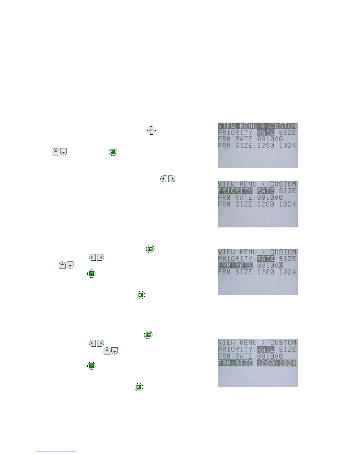
3.2.4 Custom Settings for Recording Speed and Frame Size (CUSTOM F)
While in the VIEW mode, the desired value for the recording speed and frame size can be selected from
the VIEW MENU on the J-PAD3.
Custom Settings for Recording Speed
The recording speed can be set at 1pps intervals. With frame size priority, the upper limit of the
recording speed is determined by the frame size.
Custom Settings for Frame Size
Horizontal pixels can be set in 4 pixel intervals while vertical pixels can be set in 16 pixel intervals.
With recording speed priority, the upper limit of the frame size is determined by the recording
speed
1) While in the VIEW mode, press MENU
to display the
VIEW MENU.
2) Select "CUSTOM F" from the VIEW MENU using the arrows
and press SET to display the CUSTOM F
sub-menu (Figure 3-12).
3) Select "PRIORITY" and then use the arrows
to
select either the recording speed or the frame size as
priority (Figure 3-13).
RATE
Recording speed priority
SIZE
Frame size priority
4) Select "FRM RATE" for recording speed custom settings.
-ⅰ) Select "FRM RATE" and press SET
(Figure 3-14).
-ⅱ) Use arrows to move columns and use arrows
to change the numerical value.
-ⅲ) Press SET
to set the recording speed.
With frame size priority, to set a value larger than the upper
limit for the recording speed, press
to display the value
for the upper limit.
5) Select "FRM SIZE" for the frame size custom settings.
-ⅰ) Select "FRM SIZE" and press SET
(Figure 3-15).
-ⅱ) Use arrows to change the number of horizontal
pixels and arrows
to change the number of vertical
pixels.
-ⅲ) Press SET
again to set the frame size.
With recording speed priority, to set a value larger than the upper
limit for the frame size, press SET
to display the value of the
upper limit.
Figure3-12 CUSTOM F
Figure 3-13 PRIORITY
Figure 3-14 FRM RATE(Custom)
Figure 3-15 FRM SIZE

(00235)
3-11
3.2.5 Shutter Exposure Time Selection (SHUTTER)
While in the VIEW mode, the shutter exposure time can be selected from the VIEW MENU on the J-PAD3.
The shutter exposure time can be selected from either set values or desired values can be set.
1) While in the VIEW mode, press MENU
to display the
VIEW MENU.
2) Select "SHUTTER" from the VIEW MENU using the arrows
. (Figure 3-16).
3) Use the arrows to select the shutter exposure time.
OPEN 1/ recording speed sec
100 1/ 100 sec
250 1/ 250 sec
500 1/ 500 sec
1 k 1/ 1000 sec
2 k 1/ 2000 sec
5 k 1/ 5000 sec
10 k 1/ 10,000 sec
20 k 1/ 20,000 sec
50 k 1/ 50,000 sec
100 k 1/ 100,000 sec
200 k 1/ 200,000 sec
333 k 1/ 333,333 sec
4) The left preset value shows 6 numerical columns
"******us". Select for the custom settings for the shutter
exposure time.
-ⅰ) Select "******us" and press SET
.
-ⅱ) Use arrows to change columns and use arrows
to change the numerals. (Figure 3-17).
-ⅲ) Press SET
again, to set the shutter exposure time.
The upper limit for the shutter exposure time is set according to the recording speed. To set a value
greater than the shutter exposure time, press SET
to display the value of the upper limit.
The values that can be used as custom settings for the shutter exposure time change according to the
recording speed and frame size. When SET
is pressed, the display of the possible settings
changes.
CAUTION
)
Black balance adjustment is recommend when you use a shutter of 1~5μs as black
level changes dramatically.
Selection of the shutter exposure time using the direct key
can be performed when the status
screen in the STOP mode or the VIEW mode is displayed.
The custom settings for the shutter exposure time cannot be changed with the direct key
Figure 3-16 SHUTTER
Figure 3-17 SHUTTER (Custom)

(00235)
3-12
3.2.6 Area Of Interest (AOI)
In case of use of auto exposure (AE) mode or image trigger (IMG TRIG) mode, you should specify a
reference area where luminance level is measured. Area of interest (AOI) is used for specifying the said
reference area.
Note: AOI is called as AE AREA on the J-Pad 3 ver.2.02 or earlier .
In the VIEW mode, you can set AOI from VIEW MENU of J-PAD3, as follows.
1) In the VIEW mode, press
to enter the VIEW MENU.
2) Select "AOI" from the VIEW MENU using the up/down
keys
. (Figure 3-18).
3) Use the left/right keys to select the area of interest.
FULL AOI is the whole image.
CENTER AOI is a central part of the image.
(25% of area)
UPPER AOI is an upper half of the image.
LOWER AOI is a lower half of the image.
LEFT AOI is a left half of the image.
RIGHT AOI is a right half of the image.
CUSTOM AOI specified by GXLink (*).
* Custom AOI: You can specify AOI in pixels by pixels using the GXLink. You can choose “CUSTOM”
mode by the J-PAD3 but cannot specify its area by the J-PAD3. Please refer to GXLink
User’s Manual for the custom AOI setting procedure.
Figure 3-18 AOI

(00235)
3-13
3.2.7 Image Trigger (IMG TRIG) Setting
In the VIEW mode, you can set the IMG TRIG from the VIEW MENU on the J-PAD3.
Image trigger is a function to activate as a trigger when the luminance is changed in the area specified in
AOI. However, the image trigger is not activated in case of the grad ual luminance chan ge, such as, weathe r
change. In addition, it monitors the luminance level at 7.5Hz (NTSC mode) or 6.25Hz (PAL mode). So, it
may not be activated in case of a short duration of luminance change, such as, a flash of 0.2sec or less.
When using the image trigger mode, you should set AOI (see 3.2.6) and an image trigger level.
In the VIEW mode, you can set an image trigger level by J-PAD3, as follows.
1) In the VIEW mode, press MENU
to enter the VIEW
MENU.
2) Select "IMAG TRIG" from the VIEW MENU using the
up/down keys
. (Figure 3-19)
3) Use the left/right keys to select the image trigger
level.
OFF Image trigger is off.
LOW Insensitive: The trigger is activated by large
change of luminosity.
MID Standard: The trigger is activated by medium
change of luminosity.
HIGH Sensitive: The trigger is activated by small change
of luminosity.
If the image trigger level is not suitable for the recording condition, the trigger is activated unexpectedly
[A] or is not activated as per your expectation [B]. Please try test recordings before the actual test, to
check the image trigger level. Following is reference to find a suitable image trigger level.
Setting
Suitable Conditions Not Suitable Conditions Impossible Conditions
LOW
・Recording under flickering
environment such as under a
fluorescence
・Recording in case of small
luminance change [B]
MID
・Recording in case of
luminance change entirely in
AOI, such as an explosion
・Recording if size of a
subject crossing AOI is not
sufficient against AOI. [B]
・Recording under
flickering environment
such as under a
fluorescence. [A]
HIGH
・Recording if a subject will cross
in AOI
・Recording if there will be a
moving object in AOI other
than a subject [A]
You cannot use IMG TRIG mode and AE mode simultaneously. If
you will set IMG TRIG mode while AE mode is activated, a warning
message will be displayed as shown in Fig. 3-20.
Press the SET key
to switch from AE mode to IMG TRIG
mode.
Figure 3-19 IMG TRIG
Figure 3-20

(00235)
3-14
While IMG TRIG mode is activated, "Image Trigger" is
displayed on the OSD (on screen display) in VIEW, ARM, and
REC, as shown in Fig. 3-21.
Cautions) In case of not use of the image trigger function, please make sure that IMG TRIG is OFF.
If IMG TRIG is not OFF while you want to use the external trigger signal or the trigger command from the
J-PAD3, the recording may be completed unexpectedly due to this function.
Figure3-21

(00235)
3-15
3.2.8 Automatic Exposure (AE) Control Settings
While in the VIEW mode, the automatic exposure control can be set from the VIEW MENU on the
J-PAD3.
The automatic exposure control(AEC:Automatic Exposure Control) measures the light in a specific
area of the image photographed and adjusts the shutter exposure time for the appropriate brightness of the
image. This corresponds to brightness changes outdoors (fog, time and changes in the weather).
The response speed for the automatic exposure is set to be slower and so this cannot be use d during rapid
changes in brightness (strobe lights or explosions and the like).
When using the automatic exposure control, the shutter exposure time is adjusted between the shortest
exposure time and the exposure time set as a SHUTTER item. If the time stamp is ON, the value of the
shutter exposure time for the recorded frame is saved for each frame.
1) While in the VIEW mode, press MENU
to display the
VIEW MENU.
2) Select "AE" from the VIEW MENU using the arrows
.
(
Figure 3-18)
3) Use arrows to select the adjustment level for the
automatic exposure control.
OFF
Automatic exposure control not in use
LOW
Image brightness adjusted slightly darker
NORMAL
Image brightness adjusted to normal
HIGH
Image brightness adjusted slightly brighter
3.2.9 DRES Mode Settings (DRES)
While in the VIEW mode, the DRES mode can be set from the VIEW MENU on the J-PAD3.
Using the DRES mode,(DRES:Dynamic Range Expansion Shutter), the camera sensor can control the
saturation of the area of high intensity to enable photography of wide dynamic range images.
DRES mode is used as a combination of gamma correction and lens adjustment. When in DRES mode,
gain correction and knee correction do not function.
4) While in the VIEW mode, press MENU
to display the
VIEW MENU.
5) Select "DRES" from the VIEW MENU using the arrows
. (Figure 3-20)
6) Use the arrows to select the dynamic range in DRES
mode.
OFF
The dynamic range is set to approximately 200%.
(This is the normal setting)
LOW
The dynamic range is set to approximately 400%
MID
The dynamic range is set to approximately 800%
HIGH The dynamic range is set to approximately 1600%
Figure3-23 DRES
Figure3-23 DRES
Figure 3-22 AE

(00235)
3-16
3.2.10 Recording Bit Length Settings (DEPTH)
While in the VIEW mode, the recording bit length can be set from the VIEW MENU on the J-PAD3.
It is possible to alter the number of bits per pixel for the recorded image. With a high bit rate, the gradation
of the image (the amount of change in brightness) of the image is finer and results in better image quality.
With a low bit rate, the gradation of the image is rougher and it is possible to economize on the recording
memory, and extend the recording time.
1) While in the VIEW mode, press MENU
to display the
VIEW MENU.
2) Select "DEPTH" from the VIEW MENU using the arrows
.(Figure 3-24)
3) Use the arrows to select the recording bit length.
8
8 bit
10
10 bit (standard image setting)
12
12 bit (high quality image)
3.2.11 Initial Value Settings for the Recorded Scene Number (SCENE)
While in the VIEW mode, the initial value for the recorded scene number can be set from the VIEW MENU
on the J-PAD3.
The initial value for the recorded scene can be set from 0~65535. The recorded scene number adds +1
each time recording is completed.
1) While in the VIEW mode, press MENU
to display the
VIEW MENU.
2) Select "SCENE" from the VIEW MENU using the arrows
and press SET
.(Figure 3-25).
3) Use the arrows to move columns and use arrows
to change the numerical value. (Range:0~65535)
4) Press SET
again to set the initial value for the recorded
scene number.
Figure3-24 DEPTH
Figure3-25 SCENE

(00235)
3-17
3.2.12 Memory Segment Settings (SEG SIZE)
While in the STOP mode, the number of memory segments can be set from the SYS MENU on the
J-PAD3.
The recording memory can be segmented into a maximum of 16 memory segments (4GB Model). The
recording time for segmented memory segments shortens according to the number of segments but
separate recording scenes can be saved for the numb er of segments. Also, the recorded image s for
multiple scenes can be retained and downloaded together afterwards.
The photographic conditions for each memory segment can be changed for recording.
CAUTION) Images recorded in the memory are erased when the memory segments are set. Conduct
memory segmenting after verifying whether or not erasing is acceptable.
The images required should be shaved on USB compatible recording media or on the control
PC. Refer to【2.9 Saving】or【GXLink User's Manual】 for the method of saving images.
1) While in the STOP mode, press MENU
to display the
TOP MENU.
2) Select "SYS SET" from the TOP MENU using the arrows
and press SET to display the SYS SET
sub-menu (Figure 3-26).
3) Select "SEG SIZE" and select the number of memory
segments using the arrows .
<
Memory 2GB model>
2.1GBX1 No memory segmentation
1GBX2 Segment into two 1GB segments
532MB X4 Segment into four 512MB segments
266MB X8 Segment into eight 256MB segments
<
Memory 4GB model>
4.2GBX1 No memory segmentation
2.1GBX2 Segment into two 2.1GB segments
1GBX4 Segment into four 1GB segments
532MB X8 Segment into eight 512MB segments
266MB X16 Segment into sixteen 256MB segments
4) Once the number of memory segments is selected, a
verification message verifying the memory segmentation will
be displayed (Figure 3-27).
If there are no problems erasing the images saved in the
memory, press SET
to segment the memory.
Figure 3-26 SYS SET
Figure 3-27 Verification message

(00235)
3-18
3.2.13 External Trigger Signal Selection (TRIG SEL)
While in the STOP mode, the external trigger signals can be set from the SYS MENU on the J-PAD3.
The method of inputting the recording trigger signals can be performed by operating the special remote
control J-PAD3 or via external trigger signal input from the TRIG1 connector on rear panel or the J3 cable
TRIG2 connector.
1) While in the STOP mode, press MENU to display the
TOP MENU.
2) Select "TRIG SET" from the TOP MENU using the arrows
and press SET to display the TRIG SET
sub-menu (Figure 3-28).
3) Select "TRIG SEL" and use the arrows to select the
external trigger signal.
TRIG1
Valid external trigger signal from TRIG1 connector
TRIG2
Valid external trigger signal from TRIG2 connector
External trigger signals from the J1 cable TRIG1 connector and the J3 cable TRIG2 connector cannot be
used simultaneously.
The polarity of the external trigger signals from the TRIG1 connector and TRIG2 connector can be set.
Refer to【3.2.16 Selecting Polarity for External Input/Output Signals】
3.2.13.1 External Trigger Signals from TRIG1
External trigger signal from the TRIG1 connector is input into the MEMRECAM GX-3 via TTL input or
contact input. Refer to【7 Specifications】for details.
The advantage of using these signals is the ease of use and with contact input, connection is possible
between one switch and two wires. It is recommended that this be used in a clean enviro nmen t where the re
is no external noise. Please be aware that the voltage tolerance range is quite narrow (-0.5~5.5Vdc)
3.2.13.2 External Trigger Signals from TRIG2
External trigger signal from the TRIG1 connector is input into the MEMRECAM GX-3 via current loop
input by the photo coupler. Refer to【7 Specifications】for details.
The advantage of using these signals is the excellent noise resistance and the application for long
distance cables. It is recommended that this be used in an environment where noise, such as static is often
generated. However, an ex ternal power source is needed to use this input.
3.2.13.3 Filter Value Setting
If trigger is ON by noise throgh an external trigger signal line, set the value of the noise filter to avoid
mis-trigger. Please refer to【3. 2.17 Trigger filter setting】for details of the setting procedure.
Figure3-28 TRIG SEL(TRIG SET)

(00235)
3-19
3.2.14 Recording Method Selection (REC MODE)
While in the STOP mode, the recording method can be selected from the SYS MENU on the J-PAD3.
Select the optimal recording method for our photography from the four choices below. Recording can
be performed in the AUTO mode, LOOP mode, ALL BLOCKS mode (only with multi trigger recording) and
CONTINUOUS mode (only with multi trigger recording) for each recording method.
Normal Recording [ NORMAL / NORMAL(A) / NORMAL(L) ]
Burst Recording [ BURST / BURST(A) / BURST(L) ]
Multi Trigger Recording [ MULTI(A) / MULTI(C) / MULTIS(A) / MULTIS(L) ]
Event Recording [ EVENT / EVENT(A) / EVENT(L) ]
Please be aware that depending on the recording method, there may be cases when the trigger input
from the J-PAD3 does not function. Trigger input from external trigger signals works for all recording
methods. (Table 3-4)
Table 3-4 Valid Trigger Input by Recording Method
Recording Method
Trigger Input
J-PAD3 operation External Trigger Signals
Normal Recording
○
○
Burst Recording
×
○
Multi Trigger
Recording
○
○
Event Recording
△
○
×:Trigger input from the J-PAD3 does not work with burst recording.
△:With event recording, the initial trigger input does not work from the J-PAD3 and the
external trigger input only works with the second and subsequent event trigger input.
3.2.14.1 AUTO Mode
The AUTO mode has a function that automatically performs memory segment switching when recording
stops and switching from the REC mode to the ARM mode. Continuous recording for each memory
segment. The STOP mode is a ccessed o nce re co rding to all of the memory seg ments has been completed.
Memory segments where recording has been completed are memory protected, and recording is
prohibited in AUTO mode. If the J-PAD3 is used to switch to the ARM mode, a warning message will be
displayed (Figure 3-29).
Figure 3-29 Memory Protected
Even if recording to all of the memory segments has not been completed, press ST OP
to stop
recording. Depending on the camera mode when STOP
is pressed, the number of frames saved
before recording is stopped will vary.
If STOP
is pressed during the ARM mode
If the custom setting for the trigger timing is +100%, recording stops when the same number o f
frames is saved.
If STOP
is pressed during the REC mode
Recording stops after saving from the frame where recording was started to the frame at the
instant STOP
was pressed.

(00235)
3-20
3.2.14.2 LOOP Mode
The LOOP mode has a function that automatically performs memory segment switching when recording
stops and switching from the REC mode to the ARM mode. It is different from the AUTO mode in that there
is no memory protection for memory segments upon the completion of recording. Images are overwritten
when memory segments are switched so repeated recording can be performed.
Recording is repeated until STOP
is pressed.。
CAUTION
)
It takes about 4.5 seconds for the automatic switching of memory segments. Since
triggersinput during this time may be ignored, input the trigger after verifying that you are in
the ARM mode.
3.2.14.3 Setting Method
1) While in the STOP mode, press MENU
to display the
TOP MENU.
2) Select "TRIG SET" from the TOP MENU using the arrows
and press SET to display the TRIG SET
sub-menu (Figure3-30).
3) Select "REC MODE" and use the arrows to select the
recording method.
NORMAL
Normal recording
NORMAL(A)
Normal recording in AUTO mode
NORMAL(L)
Normal recording in LOOP mode
EVENT
Event recording
EVENT(A)
Event recording in AUTO mode
EVENT(L)
Event recording in LOOP mode
BURST
Burst recording
BURST(A)
Burst recording in AUTO mode
BURST(L)
Burst recording in LOOP mode
MULTI(A)
Multi trigger recording in ALL BLOCKS mode
MULTI(C)
Multi trigger recording in CONTINUOUS mode
MULTIS(A)
Multi trigger recording in AUTO mode
MULTIS(L)
Multi trigger recording in LOOP mode
4) When selecting multi trigger recording, select "BLOCKS" to
set the number of memory block segments.
-ⅰ) Select "BLOCKS" and press SET
.
-ⅱ) Use arrows to move columns and use arrows
to change the numerical value (1
~
16).
-ⅲ) Press SET
again to set the number of blocks for multi trigger recording.
Figure 3-30 REC MODE(TRIG SET)

(00235)
3-21
3.2.14.4 Normal Recording
Normal recording is the recording method that saves images to the appropriate memory segment for a
single trigger input. The three modes within normal recording include NO RMAL, NORMAL(A) and
NORMAL(L). Refer to
【
3.2.14.3 Setting Method
】
for the method of setting normal recording.
Next is the recording sequence for each mode.
3.2.14.4.1 NORMAL
Figure 3-31 shows how to switch modes with the J-PAD3 during normal recording (top of the figure) and
saving in the memory (bottom of the figure).
The sequence for segmenting the memory into four memory segments and performing norm al recording
for memory segment 1 is shown below.
SEGMENT 2 SEGMENT 3 SEGMENT 4
STOPVIEW
ARM
SEGMENT 1
REC
switching of the Camera mode with the JPAD3 operation
automatic switching of the Camera mode
Figure 3-31 Normal Recording (NORMAL, number of segments:4)
1) Verify that the MEMRECAM GX-3 is in the STOP mode.
2) While in the STOP mode, press VIEW/ARM
on the J-PAD3 to switch to the VIEW mode.
3) While in the VIEW mode, press VIEW/ARM
on the J-P AD3 to switch to the ARM mode. While the
images are overwritten to the appropriate memory segment (SEGMENT1), it awaits trigger input.
4) While in the ARM mode, press TRIG
on the J-P AD3 or use the external trigger f or input to switch to
the REC mode. Recording will end according to the set trigger timing.
5) Once recording to the appropriate memory segment (SEGMENT1) has been completed, it switches
from the REC mode to the STOP mode.
* Press STOP
even when recording to the appropriate memory segment has not been completed to
stop recording. Depending on the camera mode when STOP
is pressed, the number of frames
saved before recording is stopped will vary.
・
If STOP
is pressed during the ARM mode
If the custom setting for the trigger timing is +100%, recording stops when the same number o f
frames is saved.
・
If STOP
is pressed during the REC mode
Recording stops after saving from the f rame where re cording wa s st arted to the f rame at the in st ant
STOP
was pressed.

(00235)
3-22
3.2.14.4.2 NORMAL(A)
Figure 3-32 shows how to switch modes with the J-PAD3 during NORMAL(A) recording (top of the figure)
and saving in the memory (bottom of the figure).
NORMAL(A) refers to normal recording in AUTO mode.
The sequence for segmenting the memory into four memory segments and performing NORMAL(A)
recording for memory segment 1 is shown below . Th e memory sh ould be empt y before recording is started.
SEGMENT 2 SEGMENT 3 SEGMENT 4SEGMENT 1
Memory Protected
ARM REC ARM REC ARM REC ARM REC
STOPVIEW STOPVIEW
switching of the Camera mode with the JPAD3 operation
automatic switching of the Camera mode and Segment
Figure 3-32 Normal Recording (NORMAL(A), Number of Segments:4)
1) Verify that the MEMRECAM GX-3 is in the STOP mode.
2) While in the STOP mode, press VIEW/ARM
on the J-PAD3 to switch to the VIEW mode.
The memory segment number (SEG) superimposed on the image is
displayed as "A". Settings in AUTO mode are displayed.
3) While in the VIEW mode, press VIEW/ARM
on the J-P AD3 to switch to the ARM mode. While the
images are overwritten to the appropriate memory segment (SEGMENT1), it awaits trigger input.
4) While in the ARM mode, press TRIG
on the J-P AD3 or use the external trigger f or input to switch to
the REC mode. Recording will end according to the set trigger timing.
5) Once recording to the appropriate memory segment (SEGMENT1) has been completed, it switches to
the next memory segment (SEGMENT2) and automatically switches from the REC mode to the ARM
mode.
6) Recording in 4)~5) is repeated, and once recording to all of the memory segment s has been completed,
it switches from the REC mode to the STOP mode. It does not switch automatically after recording on
the last memory segment (SEGMENT4).
7) Memory segments where recording has been completed are memory protected so will not swit ch to the
ARM mode. If you wish to start recording again, either change the setting to a recording method other
than the AUTO mode, or erase a memory segment.
* Press STOP
even when recording to the appropriate memory segment has not been completed to
stop recording. Depending on the camera mode when STOP
is pressed, the number of frames
saved before recording is stopped will vary.
・
If STOP
is pressed during the ARM mode
If the custom setting for the trigger timing is +100%, recording stops when the same number o f
frames is saved.
・
If STOP
is pressed during the REC mode
Recording stops after saving from the f rame where recording was started to the frame at the instant
STOP
was pressed.

(00235)
3-23
3.2.14.4.3 NORMAL(L)
Figure 3-33 shows how to switch modes with the J-PAD3 during NORMAL(L) recording (top of the figure)
and saving in the memory (bottom of the figure). NORMAL(L) refers to normal recording in LOOP mode.
The sequence for segmenting the memory into four memory segments and performing NORMAL(L)
recording for all of the memory segments is shown below.
SEGMENT 2 SEGMENT 3 SEGM ENT 4SEGMENT 1
ARM REC ARM REC ARM REC ARM REC
STOPVIEW
automatic switching of the Camera mode and Segmen t
switching of the Camera mode with the JPAD3 operation
Figure 3-33 Normal Recording (NORMAL(L), Number of Segments:4)
1) Verify that the MEMRECAM GX-3 is in the STOP mode.
2) While in the STOP mode, press VIEW/ARM
on the J-PAD3 to switch to the VIEW mode.
The memory segment number (SEG) superimposed on the image is
displayed as "L". Settings in LOOP mode are displayed.
3) While in the VIEW mode, press VIEW/ARM
on the J-P AD3 to switch to the ARM mode. While the
images are overwritten to the appropriate memory segment (SEGMENT1), it awaits trigger input.
4) While in the ARM mode, press TRIG
on the J-P AD3 or use the external trigger f or input to switch to
the REC mode. Recording will end according to the set trigger timing.
5) Once recording to the appropriate memory segment (SEGMENT1) has been completed, it switches to
the next memory segment (SEGMENT2) and automatically switches from the REC mode to the ARM
mode.
6) Recording in 4)~5) is repeated, and once recording to all of the memory segment s has been completed,
it switches to the top memory segment (SEGMENT1) and it automatically switches from the REC mo de
to the ARM mode.
The recording operation in 6) can be repeated while subsequent images are overwritten. Press STOP
to stop recording.
* Press STOP
even when recording to the appropriate memory segment has not been completed to
stop recording. Depending on the camera mode when STOP
is pressed, the number of frames
saved before recording is stopped will vary.
・
If STOP
is pressed during the ARM mode
If the custom setting for the trigger timing is +100%, recording stops when the same number o f
frames is saved.
・
If STOP
is pressed during the REC mode
Recording stops after saving from the f rame where re cording wa s st arted to the f rame at the in st ant
STOP
was pressed.
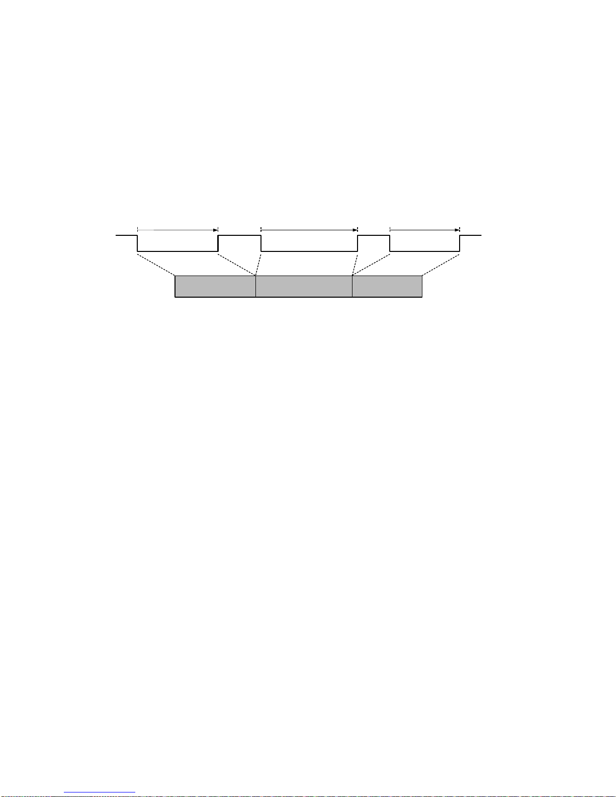
(00235)
3-24
3.2.14.5 Burst Recording
With burst recording, the frame for the amount of recording time is controlled with burst trigger signals and
saved in the memory.
Burst trigger signals can save only the desired frames from the period recorded in the memory. As shown
in Figure 3-31, only the frames during the period when the burst trigger signals are input (ON) are saved to
the memory.
Also, the recording memory is segmented into blocks according to the burst trigger signal input time
frame. When the total of the frames saved in each block reaches the numb er of frames for each recording
time, recording is completed.
Figure 3-31 shows the number of frames for each recording time saved with three burst trigger signal
inputs.
ON OFFOFF ON OFF ON OFF
Block① Block② Block③
Recoding time = Burst trigger signal input tim e(①+②+③)
Burst trigger signal
input time①
Burst trigger signal
input time②
Burst trigger signal
input time③
Memory = Block(①+②+③)
Figure 3-34 Burst Recording
The three modes within burst recording include BURST, BURST (A) and BURST (L). Refer to
【
3.2.14.3
Setting Method
】
for the method of setting burst recording.
Next are the restrictions on burst recording and the recording sequence for each mode.
3.2.14.5.1 Burst Recording Restrictions
The following restrictions apply to burst recording.
●
Burst recording cannot be combined with multi trigger recording and event recording. Recording can be
combined with EST synchronized signal recording.
●
Trigger input does not work with the J-PAD3 during burst recording. Input burst recording signals from
the TRIG1 connector on the rear panel or the J3 cable TRIG2 connector.
●
Burst recording signals can be input 16 times in the appropriate memory segment. If the time stamp is
ON and the frame time standard is set to the exposure time, the restrictions on the number of burst
recording signals is eliminated but during playback, it can jump to the top frame of each block up to 16
times.
Refer to 【5 System setting】 for 【3.2.19 TIMESTAMP Setting】, and a setting of flame time about a
setting of a time and date stamp.

(00235)
3-25
3.2.14.5.2 BURST
Figure 3-35 shows how to switch modes with the J-PAD3 during burst recording (top of the figure) and
saving in the memory (bottom of the figure). B1 and B2 refer to the blocks of segmented memory
corresponding to the burst trigger signals.
The sequence for segmenting the memory into four memory segments and performing burst recording for
memory segment 1 is shown below.
SEGMENT 2 SEGMENT 3 SEGMENT 4B1 B2
SEGMENT 1
STOPVIEW
REC
ARM
burst trigger
on
switching of the Camera mode with the JPAD3 operation
automatic switching of the Camera mode
Figure 3-35 Burst Recording (BURST, number of segments:4)
1) Verify that the MEMRECAM GX- is in the STOP mode.
2) While in the STOP mode, press VIEW/ARM
on the J-PAD3 to switch to the VIEW mode.
The frame counter (FRAME) superimposed on the image
is displayed as "B". Burst recording settings are displayed.
"BURST" is displayed for trigger timing (Trigger).
3) While in the VIEW mode, press VIEW/ARM
on the J-P AD3 to switch to the ARM mode.
During burst recording, images cannot be overwritten, even in ARM mode. Also, live images cannot be
updated.
4) While in the ARM mode, input the burst trigger signals from the TRIG1 connector on rear panel or the J3
cable TRIG2 connector to switch to the REC mode.
Images are saved only when the burst trigger signal is ON, and when live images are updated.
Recording ends after the number of frames for the appropriate memory segment (SEGMENT1) are
saved.
5) Once recording to the appropriate memory segment (SEGMENT1) has been completed, it switches to
the STOP mode from the REC mode.
* Press STOP
even when recording to the appropriate memory segment has not been completed to
stop recording. Depending on the camera mode when STOP
is pressed, the number of frames
saved before recording is stopped will vary.
・
If STOP
is pressed during the ARM mode
If the custom setting for the trigger timing is +100%, recording stops when the same number o f
frames is saved.
・
If STOP
is pressed during the REC mode
Recording stops after saving from the f rame where re cording wa s st arted to the f rame at the in st ant
STOP
was pressed.

(00235)
3-26
3.2.1 4.5.3 BURST(A)
Figure 3-36 shows how to switch modes with the J-PAD3 during BURST(A) recording (top of the figure)
and saving in the memory (bottom of the figure). BURST(A) refers to burst recording during the AUTO
recording. B1, B2, B3 and B4 refer to the blocks of segmented memory corresponding to the burst trigger
signals.
The sequence for segmenting the memory into four memory segments and performing BURS T(A)
recording for all of the memory segments is shown below . Th e memory sho uld be empty before recordin g is
started.
B1 B2 B1 B2 B3 B1 B2 B1 B2 B3 B4
SEGMENT 1 SEGMENT 2 SEGMENT 3 SEGMENT 4
STOPVIEW
REC
burst trigger
on
REC
ARM
ARM
REC REC
ARM ARM
Memory Protected
STOPVIEW
switching of the Camera mode with the JPAD3 operation
automatic switching of the Camera mode and Segment
Figure 3-36 Burst Recording (BURST(A), Number of Segments:4)
1) Verify that the MEMRECAM GX-3 is in the STOP mode.
2) While in the STOP mode, press VIEW/ARM
on the J-PAD3 to switch to the VIEW mode.
The memory segment number (SEG) superimposed on
the image is displayed as "A". Settings in AUTO mode are
displayed.
"B" is shown in the frame counter (Frame). Burst recording
settings are displayed.
"BURST" is displayed for trigger timing (Trigger).
3) While in the VIEW mode, press VIEW/ARM
on the J-P AD3 to switch to the ARM mode.
During burst recording, images cannot be overwritten, even in ARM mode. Also, live images cannot be
updated.
4) While in the ARM mode, input the burst trigger signals from the J1 cable TRIG1 connector or the J3
cable TRIG2 connector to switch to the REC mode.
Images are saved only when the burst trigger signal is ON, and when live images are updated.
Recording ends after the number of frames for the appropriate memory segment (SEGMENT1) are
saved.
5) Once recording to the appropriate memory segment (SEGMENT1) has been completed, it switches to
the next memory segment (SEGMENT2) and automatically switches from the REC mode to the ARM
mode.
6) Recording in 4)~5) is repeated, and once recording to all of the memory segment s has been completed,
it switches from the REC mode to the STOP mode. It does not switch automatically after recording on
the last memory segment (SEGMENT4).
7) Memory segments where recording has been completed are memory protected so will not swit ch to the
ARM mode. If you wish to start recording again, either change the setting to a recording method other
than the AUTO mode, or erase a memory segment.

(00235)
3-27
* Press STOP
even when recording to the appropriate memory segment has not been completed to
stop recording. Depending on the camera mode when STOP
is pressed, the number of frames
saved before recording is stopped will vary.
・
If STOP
is pressed during the ARM mode
If the custom setting for the trigger timing is +100%, recording stops when the same number o f
frames is saved.
・
If STOP
is pressed during the REC mode
Recording stops after saving from the f rame where re cording wa s st arted to the f rame at the in st ant
STOP
was pressed.
3.2.14.5.4 BURST(L)
Figure 3-37 shows how to switch modes with the J-PAD3 during BURST(L) recording (top of the figure)
and saving in the memory (bottom of the figure). BURST(L) refers to burst recording in LOOP mode. B1, B2,
B3 and B4 refer to memory segmented blocks that correspond to the burst trigger signals.
The sequence for segmenting the memory into four memory segments and performing BURS T(L)
recording for all of the memory segments is shown below.
B1 B2 B1 B2 B3 B1 B2 B1 B2 B3 B4
SEGMENT 1 SEGMENT 2 SEGM ENT 3 SEGMENT 4
STOPVIEW
REC REC
ARMARM
REC REC
ARM ARM
burst trigger
on
switching of the Camera mode with the JPAD3 operation
automatic switching of the Camera mode and Segment
Figure3-37 Burst Recording (BURST(L), Number of Segments:4)
1) Verify that the MEMRECAM GX-3 is in the STOP mode.
2) While in the STOP mode, press VIEW/ARM
on the J-PAD3 to switch to the VIEW mode.
The memory segment number (SEG) superimposed on
the image is displayed as "L". Settings in LOOP mode are
displayed.
"B" is shown in the frame counter (Frame). Burst recording
settings are displayed.
"BURST" is displayed for trigger timing (Trigger).
3) While in the VIEW mode, press VIEW/ARM
on the J-P AD3 to switch to the ARM mode.
During burst recording, images cannot be overwritten, even in ARM mode. Also, live images cannot be
updated.
4) While in the ARM mode, input the burst trigger signals from the J1 cable TRIG1 connector or the J3
cable TRIG2 connector to switch to the REC mode.
Images are saved only when the burst trigger signal is ON, and when live images are updated.
Recording ends after the number of frames for the appropriate memory segment (SEGMENT1) are
saved.

(00235)
3-28
5) Once recording to the appropriate memory segment (SEGMENT1) has been completed, it switches to
the next memory segment (SEGMENT2) and automatically switches from the REC mode to the ARM
mode.
6) Recording in 4)~5) is repeated, and once recording to all of the memory segment s has been completed,
it switches to the top memory segment (SEGMENT1) and automatically switches from the REC mode to
the ARM mode.
The recording operation in 6) can be repeated while subsequent images are overwritten. Press STOP
to stop recording.
* Press STOP
to stop recording, even when recording to the appropriate memory segment has not
been completed. Depending on the camera mode when STOP
is pressed, the number of frames
saved before recording is stopped will vary.
・
If STOP
is pressed during the ARM mode
If the custom setting for the trigger timing is +100%, recording stops when the same number o f
frames is saved.
・
If STOP
is pressed during the REC mode
Recording stops after saving from the f rame where re cording wa s st arted to the f rame at the in st ant
STOP
was pressed.
3.2.14.6 Multi Trigger Recording
With multi trigger recording, the appropriate memory segments can be segmented into a maximum of 16
uniform blocks. Triggers ar e input for each block and multiple images can be recorded separately.
Also, each time recording to blocks is completed, the blocks are switched and it automatically switches
from the REC mode to the ARM mode (ALL BLOCKS mode).
The four modes within multi trigger recording include MULTI(A), MULTI(C), MULTIS(A), and MULTIS(L).
Refer to
【
3.2.14.3 Setting Method
】
for the multi trigger recording settings and the settings for the number
of segmented blocks.
Next are the restrictions on multi trigger recording and the recording sequence for each mode.
3.2.14.6.1 Multi Trigger Recording Restrictions
The following restrictions apply to multi trigger recording.
Multi trigger recording cannot be combined with burst recording and event recording. Recording can
be combined with EST synchronized signal recording.
Automatic block switching takes about 2.5 seconds. Triggers input during this period may be
ignored so use trigger input after verifying that you are in the ARM mode.

(00235)
3-29
3.2.14.6.2 MULTI(A)
The (A) in MUL TI(A) indicates the “ALL BLOCKS” mode. In the ALL BLOCKS mode, once recording to
all of the blocks in the appropriate segment has been completed, it switches to the STOP mode.
The ALL BLOCKS mode is a basic operation of multi trigger recording. MULTI(C), MULTIS(A) and
MULTIS(L) recording can also be used.
Figure 3-38 shows how to switch modes with the J-PAD3 during MULTI(A) recording (top of the figure)
and saving in the memory (bottom of the figure).
The sequences for setting two memory segments and four blocks, and for MULTI(A) recordin g to memory
segment 1 are shown below .
SEGMENT 2B1 B2
SEGMENT 1
STOPVIEW
ARM REC
B3 B4
ARM REC ARM REC ARM REC
switching of the Camera mode with the JPAD3 operation
automatic switching of the Camera mode and Block
Figure 3-38 Multi Trigger Recording (MULTI(A), Number of Segments: 2, Number of Blocks: 4)
1) Verify that the MEMRECAM GX-3 is in the STOP mode.
2) While in the STOP mode, press VIEW/ARM
on the J-PAD3 to switch to the VIEW mode.
The frame counter (FRAME) superimposed on the image
shows "04 A". There are 4 blocks displaying the ALL
BLOCKS mode setting. r
3) While in the VIEW mode, press VIEW/ARM
on the J-P AD3 to switch to the ARM mode.
The frame counter (Frame) displays "01 A". While the
images are overwritten to block 1, it awaits trigger input.
4) While in the ARM mode, press TRIG
on the J-P AD3 or use the external trigger f or input to switch to
the REC mode. Recording will end according to the set trigger timing.
5) Once recording to the appropriate block (B1) has been completed, it switches to the next block (B2) and
automatically switches from the REC mode to the ARM mode.
6) Recording in 4)~5) is repeated, and once recording to all of the blocks in the appropriate memory
segment (SEGMENT1) has been completed, it switches from the REC mode to the ST OP mode.
* Press STOP even when recording to the appropriate memory segment has not been completed to
stop recording. Depending on the camera mode when STOP
is pressed, the number of frames
saved before recording is stopped will vary.
・
If STOP
is pressed during the ARM mode
If the custom setting for the trigger timing is +100%, recording stops when the same number o f
frames is saved.
・
If STOP
is pressed during the REC mode
Recording stops after saving from the f rame where recording was started to the frame at the instant
STOP
was pressed

(00235)
3-30
3.2.14.6.3 MULTI(C)
MUL TI(C) indicates the “CONTINUOUS” mode. In the CONTINUOUS mode, multi trigger recording can
be repeated while overwriting blocks in the appropriate segment where recording has b een completed
Figure 3-39 shows how to switch modes with the J-PAD3 during MULTI(C) recording (top of the figure)
and saving in the memory (bottom of the figure).
The sequences for setting two memory segments and four bl ocks, and for MULTI(A) recording to memory
segment 1 are shown below .
SEGMENT 2
B1 B2
SEGMENT 1
STOPVIEW
ARM REC
B3 B4
ARM REC ARM REC ARM REC
switching of the Camera mode with the JPAD3 operation
automatic switching of the Camera mode and Block
Figure 3-39 Multi Trigger Recording (MULTI(C), Number of Segments: 2, Number of Blocks: 4)
1) Verify that the MEMRECAM GX-3 is in the STOP mode.
2) While in the STOP mode, press VIEW/ARM
on the J-PAD3 to switch to the VIEW mode.
The frame counter (FRAME) superimposed on the image
shows "04 C". There are 4 blocks displaying the
CONTINUOUS mode setting.
3) While in the VIEW mode, press VIEW/ARM
on the J-P AD3 to switch to the ARM mode.
The frame counter (Frame) displays "01 C". While the
images are overwritten to block 1, it awaits trigger input.
4) While in the ARM mode, press TRIG
on the J-P AD3 or use the external trigger f or input to switch to
the REC mode. Recording will end according to the set trigger timing.
5) Once recording to the appropriate block (B1) has been completed, it switches to the next block (B2) and
automatically switches from the REC mode to the ARM mode.
6) Recording in 4)~5) is repeated, and once recording to all of the blocks in the appropriate memory
segment (SEGMENT1) has been completed, it switches to the top block (B1) and automatically
switches from the REC mode to the ARM mode.
The recording operation from 6) can be repeated while subsequent images are overwritten. Press
STOP
to stop recording.
* Press STOP
even when recording to the appropriate memory segment has not been completed to
stop recording. Depending on the camera mode when STOP
is pressed, the number of frames
saved before recording is stopped will vary.
・
If STOP
is pressed during the ARM mode
If the custom setting for the trigger timing is +100%, recording stops when the same number o f
frames is saved.
・
If STOP
is pressed during the REC mode
Recording stops after saving from the f rame where recording was started to the frame at the instant
STOP
was pressed

(00235)
3-31
3.2.14.6.4 MULTIS(A)
Figure 3-40 shows how to switch modes with the J-PAD3 during MULTIS(A) recording (top of the figure)
and saving in the memory (bottom of the figure). MULTIS(A) is multi trigger recording in the AUTO mode.
The sequences for setting two memory segments and four blocks, and for MULTIS(A) recording to all of
the memory segments are shown below.
The memory should be empty before recording is started.
B1 B2
SEGMENT 1
STOPVIEW
ARM REC
B3 B4
ARM REC ARM REC ARM REC
B1 B2
SEGMENT 2
B3 B4
ARM REC ARM REC ARM REC ARM REC
Memory
Protected
STOP
VIEW
switching of the Camera mode with the JPAD3 operation
automatic switching of the Camera mode, Segment and Block
Figure3-40 Multi Trigger Recording (MULTIS(A), Number of Segments: 2, Number of Blocks: 4)
1) Verify that the MEMRECAM GX-3 is in the STOP mode.
2) While in the STOP mode, press VIEW/ARM
on the J-PAD3 to switch to the VIEW mode.
The memory segment number (SEG) superimposed on
the image shows "A". The AUTO mode settings are
displayed.
The frame counter (FRAME) superimposed on the image
shows "04 A". There are 4 blocks displaying the ALL
BLOCKS mode setting.
3) While in the VIEW mode, press VIEW/ARM
on the J-P AD3 to switch to the ARM mode.
The frame counter (Frame) displays "01 A". While the
images are overwritten to block 1, it awaits trigger input.
4) While in the ARM mode, press TRIG
on the J-P AD3 or use the external trigger f or input to switch to
the REC mode. Recording will end according to the set trigger timing.
5) Once recording to the appropriate block (B1) has been completed, it switches to the next block (B2) and
automatically switches from the REC mode to the ARM mode.
6) Repeat recording in 4)~5), and once recording to all of the blocks in the appropriate memory segment
(SEGMENT1) has been completed, it switches to the next memory segment (SEGMENT2) and
automatically switches from the REC mode to the ARM mode.
7) If the recording operation from 6) is repeated and recording to all of the memory segments has been
completed, it switches from the REC mode to the STOP mode. The memory segment does not
automatically switch after the final memory segment (SEGMENT2) recorded.
Memory protection applies to memory segments where the recording has been completed so it does
not switch to the ARM mod e. If you want to record again, either change the settings to a recording
method other than the AUTO mode, or erase the memory segment.

(00235)
3-32
* Press STOP
even when recording to the appropriate memory segment has not been
completed to stop recording. Depending on the camera mode when STOP
is pressed, the number
of frames saved before recording is stopped will vary.
・
If STOP
is pressed during the ARM mode
If the custom setting for the trigger timing is +100%, recording stops when the same number o f
frames is saved.
・
If STOP
is pressed during the REC mode
Recording stops after saving from the frame where recording was started to the frame at the instant
STOP
was pressed
※
3.2.14.6.5 MUL TIS(L)
Figure 3-41 shows how to switch modes with the J-PAD3 during MULTIS(L) recording (top of the figure)
and saving in the memory (bottom of the figure). MULTIS(L) is multi trigger recording in the LOOP mode.
The sequences for setting two memory segments and four blocks, and for MULTIS(L) recording to all of
the memory segments are shown below.
B1 B2
SEGMENT 1
STOPVIEW
ARM REC
B3 B4
ARM REC ARM REC ARM REC
B1 B2
SEGMENT 2
B3 B4
ARM REC ARM REC ARM REC ARM REC
switching of the Camera mode with the JPAD3 operation
automatic switching of the Camera mode, Segment and Block
Figure3-41 Multi Trigger Recording (MULTIS(L), Number of Segments: 2, Number of Blocks: 4)
1) Verify that the MEMRECAM GX-3 is in the STOP mode.
2) While in the STOP mode, press VIEW/ARM
on the J-PAD3 to switch to the VIEW mode.
The memory segment number (SEG) superimposed on
the image shows "L". The LOOP mode settings are
displayed.
The frame counter (FRAME) superimposed on the image
shows "04 A". There are 4 blocks displaying the ALL
BLOCKS mode setting.
3) While in the VIEW mode, press VIEW/ARM
on the J-P AD3 to switch to the ARM mode.
The frame counter (Frame) displays "01 A". While the
images are overwritten to block 1, it awaits trigger input.
4) While in the ARM mode, press TRIG
on the J-P AD3 or use the external trigger f or input to switch to
the REC mode. Recording will end according to the set trigger timing.
5) Once recording to the appropriate block (B1) has been completed, it switches to the next block (B2) and
automatically switches from the REC mode to the ARM mode.

(00235)
3-33
6) Repeat recording in 4)~5), and once recording to all of the blocks in the appropriate memory segment
(SEGMENT1) has been completed, it switches to the next memory segment (SEGMENT2) and
automatically switches from the REC mode to the ARM mode.
7) If the recording operation from 6) is repeated and recording to all of the memory segments has been
completed, it switches to the top block (B1) of the top memory segment (SEGMENT1) and
automatically switches from the REC mode to the STOP mode.
The recording operation in 7) can be repeated while overwriting subsequent images. Press STOP
to stop recording.
* Press STOP
even when recording to the appropriate memory segment has not been completed to
stop recording. Depending on the camera mode when STOP
is pressed, the number of frames
saved before recording is stopped will vary.
・
If STOP
is pressed during the ARM mode
If the custom setting for the trigger timing is +100%, recording stops when the same number o f
frames is saved.
・
If STOP
is pressed during the REC mode
Recording stops after saving from the f rame where recording was started to the frame at the instant
STOP
was pressed
3.2.14.7 Event Recording
With event recording, the first trigger input is treated as a normal recording trigger signal and the second
and subsequent trigger inputs are treated as event triggers. An identification mark, called an event frame, is
input on the image the instant the event trigger occurs.
The three modes within event recording include EVENT, EVENT(A) and EVENT (L). Refer to
【
3.2.14.3
Setting Method
】
for the method of setting event recording.
Next are the event recording restrictions and the recording sequence for each mode.
3.2.14.7.1 Event Recording Restrictions
The following restrictions apply to event recording.
Event recording cannot be combined with burst recording and multi trigger recording. Recording
can be combined with EST synchronized signal re cording.
The first trigger input can be input using the J-PAD3 but continuous event trigger input is not
possible with the J-PAD3. Input event trigger signals from the J1 cable TRIG1 connector on the
rear panel or the J3 cable TRIG2 connector.

(00235)
3-34
3.2.14.7.2 EVENT
Figure 3-42 shows how to switch modes with the J-PAD3 during event recording (top of the figure) and
saving in the memory (bottom of the figure).
The sequence for segmenting the memory into four memory segments and performing event reco rding
for memory segment 1 is shown below.
SEGMENT 2 SEGMENT 3 SEGMENT 4SEGMENT 1
event
trigger
STOPVIEW
ARM REC
automatic switching of the Camera mode
switching of the Camera mode with the JPAD3 operation
Figure 3-42 Event Recording (EVENT, number of segments:4)
1) Verify that the MEMRECAM GX-3 is in the STOP mode.
2) While in the STOP mode, press VIEW/ARM
on the J-PAD3 to switch to the VIEW mode.
The frame counter (FRAME) superimposed on the image
is displayed as "E". Event recording settings are displayed.
3) While in the VIEW mode, press VIEW/ARM
on the J-P AD3 to switch to the ARM mode. While the
images are overwritten to the appropriate memory segment (SEGMENT1), it awaits trigger input.
4) While in the ARM mode, press TRIG
on the J-P AD3 or use the external trigger f or input to switch to
the REC mode. Continue to input event trigger signals from the TRIG1 connector on rear panel or the
J3 cable TRIG2 connector to save the event frames. Recording will end according to the set trigger
timing.
5) Once recording to the appropriate memory segment (SEGMENT1) has been completed, it switches
from the REC mode to the STOP mode.
* Press STOP
even when recording to the appropriate memory segment has not been completed to
stop recording. Depending on the camera mode when STOP
is pressed, the number of frames
saved before recording is stopped will vary.
・
If STOP
is pressed during the ARM mode
If the custom setting for the trigger timing is +100%, recording stops when the same number o f
frames is saved.
・
If STOP
is pressed during the REC mode
Recording stops after saving from the f rame where recording was started to the frame at the instant
STOP
was pressed

(00235)
3-35
3.2.14.7.3 EVENT(A)
Figure 3-43 shows how to switch modes with the J-PAD3 during EVENT(A) recording (top of the figure)
and saving in the memory (bottom of the figure). EVENT (A) refers to event recording in the AUTO mode.
The sequences for setting four memory segments and for EVENT(A) recording to all of the memory
segments are shown below.
The memory should be empty before recording is started.
SEGMENT 2 SEGMENT 3 SEGMENT 4SEGMENT 1
Memory Protected
ARM REC ARM REC ARM REC ARM REC
STOPVIEW STOPVIEW
event
trigger
automatic switching of the Camera mode and Segment
switching of the Camera mode with the JPAD3 operation
Figure 3-43 Event Recording (EVENT(A), Number of Segments: 4)
1) Verify that the MEMRECAM GX-3 is in the STOP mode.
2) While in the STOP mode, press VIEW/ARM
on the J-PAD3 to switch to the VIEW mode.
The memory segment number (SEG) superimposed on
the image shows "A". The AUTO mode settings are
displayed.
The frame counter (Frame) shows "E". The event
recording settings are displayed.
3) While in the VIEW mode, press VIEW/ARM
on the J-P AD3 to switch to the ARM mode.
While the images are overwritten to the appropriate memory segment (SEGMENT1), it await s trigg er
input.
4) While in the ARM mode, press TRIG
on the J-P AD3 or use the external trigger f or input to switch to
the REC mode. Continue to input event trigger signals from the TRIG1 connector on rear panel or the
J3 cable TRIG2 connector to save the event frames. Recording will end according to the set trigger
timing.
5) Once recording to the appropriate memory segment (SEGMENT1) has been completed, it switches to
the next memory segment (SEGMENT2) and automatically switches from the REC mode to the ARM
mode.
6) Repeat recording in 4)~5), and once recording to all of the memory segments has been completed, it
switches from the REC mode to the STOP mode. The memory segment does not automatically switch
after the final memory segment (SEGMENT4) recorded.
7) Memory protection applies to memory segments where the recording has been completed so it does
not switch to the ARM mod e. If you want to record again, either change the settings to a recording
method other than the AUTO mode, or erase the memory segment.

(00235)
3-36
* Press STOP
even when recording to the appropriate memory segment has not been completed to
stop recording. Depending on the camera mode when STOP
is pressed, the number of frames
saved before recording is stopped will vary.
・
If STOP
is pressed during the ARM mode
If the custom setting for the trigger timing is +100%, recording stops when the same number o f
frames is saved.
・
If STOP
is pressed during the REC mode
Recording stops after saving from the f rame where recording was started to the frame at the instant
STOP
was pressed.
3.2.14.7.4 EVENT(L)
Figure 3-44 shows how to switch modes with the J-PAD3 during EVENT(L) recording (top of the figure)
and saving in the memory (bottom of the figure). EVENT(L) is event recording in the LOOP mode.
The sequences for setting four memory segments and for EVENT(L) recording to all of the memory
segments are shown below.
SEGMENT 2 SEGMENT 3 SEGMENT 4SEGMENT 1
ARM REC ARM REC ARM REC ARM REC
STOPVIEW
event
trigger
automatic switching of the Camera mode and Segment
switching of the Camera mode with the JPAD3 operation
Figure 3-44 Event Recording (EVENT(L), Number of Segments: 4)
1) Verify that the MEMRECAM GX-3 is in the STOP mode.
2) While in the STOP mode, press VIEW/ARM
on the J-PAD3 to switch to the VIEW mode.
The memory segment number (SEG) superimposed on
the image shows "L". The LOOP mode settings are
displayed.
The frame counter (Frame) shows "E". The event
recording settings are displayed.
3) While in the VIEW mode, press VIEW/ARM
on the J-P AD3 to switch to the ARM mode.
While the images are overwritten to the appropriate memory segment (SEGMENT1), it await s trigg er
input.
4) While in the ARM mode, press TRIG
on the J-P AD3 or use the external trigger f or input to switch to
the REC mode. Continue to input event trigger signals from the TRIG1 connector on rear panel or the
J3 cable TRIG2 connector to save the event frames. Recording will end according to the set trigger
timing.
5) Once recording to the appropriate memory segment (SEGMENT1) has been completed, it switches to
the next memory segment (SEGMENT2) and automatically switches from the REC mode to the ARM
mode.

(00235)
3-37
6) Repeat recording in 4)~5), and once recording to all of the memory segments has been completed, it
switches to the top memory segment (SEGMENT1) and automatically switches from the REC mode to
the STOP mode.
The recording operation in 6) can be repeated while subsequent images are overwritten. Press STOP
to stop recording.
* Press STOP
even when recording to the appropriate memory segment has not been completed to
stop recording. Depending on the camera mode when STOP
is pressed, the number of frames
saved before recording is stopped will vary.
・
If STOP
is pressed during the ARM mode
If the custom setting for the trigger timing is +100%, recording stops when the same number o f
frames is saved.
・
If STOP
is pressed during the REC mode
Recording stops after saving from the f rame where re cording wa s st arted to the f rame at the in st ant
STOP
was pressed.

(00235)
3-38
3.2.15 Synchronized Timing Selection (SYNC TIME)
While in the STOP mode, the synchronize timing can be selected from the SYS MENU on the J-PAD3.
The MEMRECAM GX-3 can be synchronized with the time on the timer of the device where connected.
Camera Synchronized Time
Synchronized timing with the internal camera timer. Select if the MEMRECAM GX-3 is used
alone or if there is no need for precise synchronization. If a control PC is connected,
synchronization with the PC time is possible.
GX-HUB Synchronized Time
Synchronized timing with the internal GX-HUB timer. Select if there are multiple camera
connections using the GX-HUB. If a control PC is connected, synchronization with the PC time is
possible.
IRIG Synchronized Time
Synchronized timing with the IRIG-B time code. Select from the following.
・If the MEMRECAM GX-3 used alone and the IRIG-B time code is input from the J3 cable
IRIG-B connector
・If multiple cameras are connected using the GX-HUB and the IRIG-B time code is input to the
GX-HUB
・If multiple cameras are connected to the MEMRECAM GX-3 and another camera from the
MEMRECAM series, and the GX-HUB is connected to the M-HUB, and the IRIG-B time code
is input to the M-HUB
3.2.15.1 Setting Method
1) While in the STOP mode , press MENU
to display the
TOPTOP MENU.
2) Use the arrows
to select “SYS MENU” from the TOP
MENU , and then press SET
to display SYS MENU.
3) Use the arrows
to select “SYNCTIME” from the SYS
MENU(Figure 3-45)。
4) Use the arrows to select the synchronized time.
ASYNC Synchronized with the internal timer of the camera
GX-HUB Synchronized with the internal timer of the GX-HUB
IRIG Synchronized with the IRIG-B time code
Refer to the 【GX-HUB User's Manual】 for multiple connections using the GX-HUB.
3.2.15.2 IRIG Synchronized Time
Confirm whether or not the time is synchronized with the IRIG-B time code on the VIEW screen.
1) While in the STOP mode, press VIEW/ARM
on the J-PAD3
to switch to the VIEW mode.
2) If "Ⅰ" is displayed in green in the frame counter superimposed
over the image, it is synchronized to the standard timing of the
IRIG-B time code.
3) If "Ⅰ" is displayed in red, the IRIG-B time code is not input
properly.
Figure3-45 SYNC SEL

(00235)
3-39
3.2.16 Synchronized Signal Selection (SYNC SEL)
While in the STOP mode, the synchronized signals can be selected from the SYS MENU on the J-PAD3.
The MEMRECAM GX-3 uses the starting time for sensor exposure as the standard for recording. The
exposure time is synchronized with the internal time signals or the external time signals shown below.
Internal Time Signals(INT)
Synchronized with the synchronized signals (VD signals) in the camera.
External Time Signals(EST2)
If EST2 is selected, the exposure start signals (EST:External Shutter Trigger, Exposure Start)
input from the J3 cable EST2 connector is the standard. The minim um frequency for the EST
signal is 0Hz so ultra high speed recording is possible.
3.2.16.1 Setting Method
1) While in the STOP mode, press MENU
to display the
TOP MENU.
2) Use the arrows
to select "SYS MENU" from the TOP
MENU, and then press SET
to display the SYS MENU.
3) Use the arrows
to select "SYNC SEL" from the SYS
MENU (Figure 3-43).
4) Use the arrows to select the synchronized signals.
INT Synchronized with the internal synchronization signals of the camera
EST2 Synchronized with the EST2 signal from the J3 connector
It is possible to set the polarity of the exposure start signal from the EST2 connector.
Refer to【3.2.16 External Input/Output Signal Polarity Selection】.
3.2.16.2 Synchronized EST Signal Recording
3.2.16.2.1 Precautions for Use
1) Filter Value Settings
If there is noise in the EST signal, set a noise filter value to activate the filter. Refer to the
【3. 2.18 EST filter setting】for the setting method.
2) Timing Restrictions
The relationship between the cycle for the EST signal and the maximum recording speed must fulfill
the following conditions. If they are not met, proper recording is not possible.
EST signal cycle > 1 / maximum recording speed
The relationship between the cycle for the EST and the shutter exposure time must also fulfill the
following conditions. If they are not met, proper recording is not possible.
EST signal cycle > shutter exposure time+5.84μsec
Figure 3-46 SYNC SEL

(00235)
3-40
3.2.16.2.2 Display During Recording
Operation can be verified during synchronized EST signal recordi ng by the imag e and the rea r pa nel LED
display.
1) VIEW Mode
Verify that “EST2” is displayed in the recording speed superimposed on
the image and that synchronized signal setting shows EST2.
While in the VIEW mode, the rear panel CM LED flashes in white.
2) ARM Mode
While in the ARM mode, the rear panel CM LED flashes in magenta.
3) REC Mode
While in the REC mode, the rear panel CM LED flashes in orange.

(00235)
3-41
3.2.17 Sync Signal Setting in VIEW mode (EST VIEW)
In case of the EST mode, the images are not captured unless the external signal is input to the camera
basically. EST VIEW allows you to switch the sync signal between the internal clock signal and the external
sync signal for the live image display in VIEW. For example, if you set EST VIEW at OFF, it allows you to
monitor the live images in VIEW using internal clock signal even if the external signal is not input (not ready)
to the camera.
EST VIEW OFF: Live images are synchronized with the internal clock signal in VIEW.
When you turn to ARM and REC, the sync signal is switched to the external sync
signal from the internal clock signal.
EST VIEW ON: Live images are synchronized with the external sync signal in VIEW.
i.e. The sync signal is always the external sync signal in the VIEW, ARM and REC.
1) In the STOP mode, press MENU
to enter the TOP
MENU.
2) Use the up/down keys
to select "SYS MENU" from
the TOP MENU, and then press SET
to enter the SYS
MENU.
3) Use the up/down keys
to select “EST VIEW “from the
SYS MENU (Figure 3-47).
4) Use the left/right keys to select the synchronized
signal setting at VIEW mode.
OFF Internal clock sync in VIEW.
ON EST sync in VIEW.
Attention)If the EST mode is used under the condition that the Time Stamp is "OFF" and the Frame
Counter Display is "TIME" or "ABS.TIME", the time is not displayed as follows.
, .
Figure 3-47 EST VIEW

(00235)
3-42
3.2.18 External Input/Output Signal Polarity Selection and Filter setting(SIG SET)
While in the STOP mode, the polarity of the external input/output signal can be selected from the SYS
MENU on the J-PAD3.
3.2.18.1
External Input/Output Signal Polarity Selection
With the external input/output signals shown below, the polarity can be set to either a rising or a falling
edge.
External Trigger Input(TRIG1,TRIG2)
External Synchronized Signal Input(EST2)
Exposure Pulse Output(EPO)
1) While in the STOP mode, press MENU
to display the
TOP MENU.
2) Use the arrows
to select "SYS MENU" from the TOP
MENU and press SET
to display the SYS MENU.
3) Use the arrows
to select "SIG SET" from the SYS
MENU and press SET
to display the SIG SET
sub-menu (Figure3-48).
4) Select the external input/output signal to be set and use the
arrows to select the polarity.
TRIG1 POSI Search for the external trigger signal from the TRIG1 connector on rear
panel by the rising edge
NEGA Search for the external trigger signal from the TRIG 1 connector on rear
panel by the falling edge
TRIG2 CRNTON Search for the external trigger signal from the J3 cable by the rising edge
CRNTOFF Search for the external trigger signal from the J3 cable by the falling edge
EST2 POSI Search for the EST signal from the J3 cable by the rising edge
NEGA Search for the EST signal from the J3 cable by the falling edge
EPO POSI Output the H level signal during exposure
NEGA Output the L level signal during exposure
Figure 3-48 SIG SET

(00235)
3-43
3.2.18.2
TRIGER Filter Setting (TRIGFLT)
MEMRECAM GX-3 equips digital noise fileter. If there is noisy electrical environment, you can filter noise
by increasing the filter value.
Filter value shows a delay time in case of trigger signal input by clean square waveform with out chattering.
You can set the value from 0.0 to 6553.5μsec in 0.1μsec increment.
Filter value shall be applied to both external trigger inputs (TRIG1 & TRIG2).
However, in case of TRIG1(Rear panel) in polarity setting of NEGA, 1.4μsec is always added to a delay
time. Also, in case of TRIG1( Rear pan el ) in polarity setting of POSI , 30μsec is added to a delay time.
In case of TRIG2( though J3) in polarity setting of CRNON, 5μsec is always added to a delay time. Also,
in case of TRIG2( though J3) in polarity setting of CRNTOFF, 150μsec is added to a delay time.
1) Press MENU key
in STOP mode to enter TOP MENU.
2) Press up/down keys
to go SYS MENU. Then press SET
key
to enter SYS MENU.
3) Press up/down keys
to go SIG SET. Then press SET
key
to enter sub menu of SIG SET.
4) Select TRIGFLT and push SET Key
(Fig 3-49).
5) Press left/right keys to move a figure, press up/down
keys to chage a value (range: 0.0~6553.5μsec).
6) Press SET key
to set the filter value.
Figure3-49 TRIGFLT

(00235)
3-44
3.2.18.3 EST Filter setting (EST FLT)
MEMRECAM GX-3 equips digital noise filter. If there is noisy electrical environment, you can filter noise
by increasing the filter value.
Filter value shows a delay time in case of trigger signal input by clean square waveform with out chattering.
You can set the value from 0.0 to 6553.5μsec in 0.1μsec increment .
This filter value is applied to an EST input (EST2).
However, in case of EST2(t hough J3) in polarity setting of NEGA, 1.4μsec is always added to a delay
time. Also, in case of polarity setting of POSI , 30μsec is added to a delay time.
1) Press MENU key
in STOP mode to enter TOP MENU.
2) Press up/down keys
to go SYS MENU. Then press SET
key
to enter SYS MENU.
3) Press up/down keys
to go SIG SET. Then press SET
key
to enter sub menu of SIG SET.
4) Select EST FLT and press SET Key
(Fig 3-50).
5) Press left/right keys to move a figure, press up/down
keys to chage a value (range: 0.0~6553.5μsec).
6) Press SET key
to set the filter value.
Figure3-50 EST FLT

(00235)
3-45
3.2.19 Time Stamp Recording Setting (TIMSTAMP)
You can set the Time Stamp Recording by SYS MENU of J-Pad 3 in STOP mode.
Time Stamp Recording enables to record the following information on each frame during recording.
Eposure time (D/H/M/S in mmin、 in usec)
Trigger Time (D/H/M/S in mmin in usec)
Event
IRIG Lock
1) Press MENU key
in STOP mode to enter TOP MENU.
2) Press up/down keys
to go SYS MENU. Then press
SET key
to enter SYS MENU.
3) Press up/down keys
to go TIMESTAMP (Fig 3-51).
4) Press left/right keys to turn on/off Time Stamp
Recording.
OFF Disable Time Stamp Recording
ON Enable Time Stamp Recording
Figure 3-51 TIMSTAMPFigure 3-51 TIMSTAMP

(00235)
3-46
3.2.20 Exposure Timing Selection (EXP TIME)
While in the STOP mode, the sensor exposure timing for synchronized signal recording can be selected
from the SYS MENU on the J-PAD3.
The sensor exposure timing for synchronized signal recording is different depending on the MEMRECAM
GX-3 or other MEMRECAM series cameras (fx,ci cameras). When conducting synchronized recording with
the MEMRECAM GX-3 and other MEMRECAM series cameras, the exposure timing for all of the cameras
must be coordinated.
1) While in the STOP mode, press MENU
to display the
TOP MENU.
2) Use the arrows
to select "SYS MENU" from the TOP
MENU and press SET
to display the SYS MENU.
3) Use the arrows
to select "EXP TIME" from the SYS
MENU. (Figure3-52)
4) Use the arrows to select the exposure time.
GXnative
Start exposure with rising synchronized signal recording
(Setting only when recording in GX-3)
K3compat
End exposure with rising synchronized signal recording
(Setting only with synchronized recording with fx series
cameras other than fx-K4 and K5)
K4compat
End exposure with rising synchronized signal recording
(Setting for synchronized recording with fx-K4 and K5)
CAUTION) Refer to a【GXLink User's Manual】for the synchronized recording by the multi-camera
connection between MEMRECAM GX-3 and other MEMRECAM series cameras.
Figure3-52 EXP TIME

(00235)
3-47
3.3 Live Image / Playback Image Settings
The image quality of the live images displayed during photographing and the playback images displayed
after photographing can be adjusted. It is also possible to zoom the images and have scroll display.
3.3.1 Gain (GAIN)
Sets the image sensitivity.
3.3.1.1 Gain Settings for Live Images
1) While in the VIEW mode, press MENU
to display the
VIEW MENU.
2) Use the arrows
to select "GAIN" from the VIEW
MENU. (Figure 3-53)
3) Use the arrows to select the gain.
LOW
One level lower than NORMAL sensitivity
NORMAL
Standard sensitivity setting
HIGH
One level higher than NORMAL sensitivity
3.3.1.2 Gain Settings for Playback Images
1) While in the STOP mode, press MENU
to display the
TOP MENU.
2) Use the arrows
to select "GAIN" from the TOP MENU.
(
Figure 3-54)
3) Use the arrows to select the gain.
LOW
One level lower than NORMAL sensitivity
NORMAL
Standard sensitivity setting
HIGH
One level higher than NORMAL sensitivity
Figure 3-53 GAIN(VIEW MENU)
Figure 3-54 GAIN(TOP MENU)

(00235)
3-48
3.3.2 Enhance (ENHANCE)
Sets the profile enhancement for the image.
3.3.2.1 Enhance Settings for Live Images
1) While in the VIEW mode, press MENU
to display the
VIEW MENU.
2) Use the arrows
to select "ENHANCE" from the VIEW
MENU. (Figure3-55)
3) Use the arrows to select the enhance.
OFF
No profile enhancement
LOW
Low profile enhancement
NORMAL
Normal profile enhancement
HIGH
High profile enhancement
3.3.2.2 Enhance Settings for Playback Images
1) While in the STOP mode, press MENU
to display the
TOP MENU.
2) Use the arrows
to select "ENHANCE" from the TOP
MENU. (Figure3-56)
3) Use the arrows to select the enhance.
OFF
No profile enhancement
LOW
Low profile enhancement
NORMAL
Normal profile enhancement
HIGH
High profile enhancement
Figure 3-55 ENHANCE(VIEW MENU)
Figure 3-56 ENHANCE(TOP MENU)
 Loading...