

Page 1

TTV678-300/400T
Ride - on Scrubber Drier
Operator Instruction Manual
WARNING! Read instructions before using this machine
Original Instructions
Page 2

Index
!
Before continuing, please refer to Quick Set Up Guide on Page 7
Page 2
!
Machine overview
Control panel overview
Safety Precautions
Rating label / Personal Protective Equipment / Recycling
Quick set-up guide
Machine set-up
Fitting the side pod skirts
Fitting the oor tool
Fitting the brushes
Setting the width
Filling the clean-water tank
Chemical dosing system
Pre-cleaning advice
Machine Operation
Lowering the brush-deck
Page 3
Page 4
Page 5
Page 6
Page 7
Page 8
Page 8
Page 9
Page 10
Page 10
Page 11
Page 11
Page 12
Lowering the oor tool
Adjusting the seat
Setting the cleaning controls
Setting the operator pre-set buttons
Waste tank warning light
Brush pressure / load adjustment
Emergency stop button and horn
Machine usage advice
Breakaway oor-tool feature
Off-aisle cleaning kit ( optional )
Machine Cleaning
Tanks and Filters
Floor tool
Machine Charging
Motor brake disengage lever / Towing / Free-wheel function
Page 12
Page 13
Page 13
Page 14
Page 14
Page 14
Page 15
Page 15
Page 16
Page 16
Page 17
Page 18
Page 19
Page 120
Battery care / Trip sequences / Trouble shooting / recommended spare parts
Warranty
Wiring Diagrams
Specications
Declaration document
Quality assurance certicate and serial number
2
233890 05/11 (A03)
Page 21 to 25
26
Page 28 to 29
Page 30
Page 31
Back Cover
Page 3

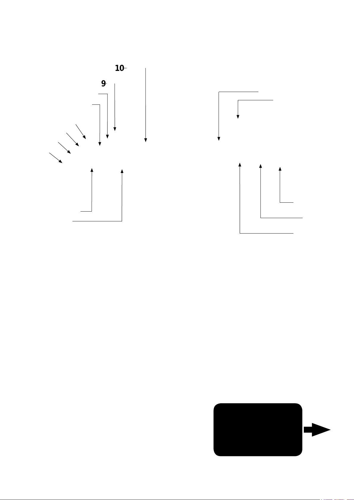
Machine Overview
22
1
9
2
3
11
4
10
5
6
7
8
12
13
14
6
15
21
18 19 20
16
17
1. Operator control panel ( see page 4 )
2. Brush load-adjuster knob
3. Brush deck-release lever
4. Brush deck-foot pedal
5. Clean water tank ll point
6. Side pod and skirt
7. Brush deck motors x3
8. Brush deck cover adjustment / width lever
9. Floor tool raise / lower lever
10. Seat adjustment lever
11. Separator release catches
12. 30 Amp battery fuses x4 ( 8 battery machine )
40 Amp battery fuses x3 ( 6 battery machine )
13. Gel batteries (606167)
14. Chemical dosing tank ( 4 litre )
15. Accelerator pedal
16. Clean water tank emptying hose
17. Semi parabolic oor-tool
18. Vacuum hose
19. Waste water emptying hose
20. Floor tool vacuum hose
21. Air separator assembly
22. Pedestrian warning light
233890 05/11 (A03)
3
Page 4
Control Panel Overview
10
9
8
7
6
5
4
3
2
1
11
12
13
14
1
2
3
4/5/6
7
8
Battery Charge Level Indicator
Brush Pressure / Load Indicator
Clean Speed Button
Operator Pre-set Buttons
Water Flow Rate Indicator
Brush Speed Indicator
Off Aisle Vacuum Button
11
Main Control ON/OFF Key
12
Machine ‘OFF’ Isolator Button
13
Forward / Reverse Switch
14
Horn
15
15
For full easy to follow
9
10
4
Chemical Mix Indicator
Waste Water ‘Full’ Indicator
233890 05/11 (A03)
control panel set up and use,
Instructions on
see machine operation
page 14
Page 5

Safety Precautions
Means:-
CAUTION:
Read the instruction manual before using the appliance.’
The TTV is a class 1 product when tted with an AC supply lead, but a class 3 product during normal use.
NOTE:
This product meets the requirements of BS EN 60335-22.72 sub clause 20.1
This machine is also suitable for commercial use, for example in hotels, schools, hospitals, factories, shops and ofces for other than normal housekeeping purposes.
Never attempt to ll the machine’ s water tanks whilst it is charging.
Machines left unattended shall be secured against unintentional movement.
Care should be taken in the choice of chemicals, detergents and other liquids. Consult your supplier.
DO’S AND DON’TS:
DO ensure only competent persons unpack/assemble the machine.
DO keep your machine clean.
DO keep your brushes in good condition.
DO replace any worn or damaged parts immediately.
DO regularly examine the charger lead for damage, such as cracking or ageing. If damage is found, replace the lead before further use.
DO only replace the charger lead with the correct Numatic approved replacement part.
DO ensure that the work area is clear of obstructions and / or people.
DO ensure that the working area is well illuminated.
DO pre-sweep the area to be cleaned.
DON’T use steam cleaners or pressure washers to clean the machine or use in the rain.
DON’T Don’t attempt machine maintenance or cleaning unless the power plug has been removed from the supply outlet,
if the machine is in charge mode or remove the key if in normal use.
DON’T allow any inexperienced repairs. Contact your nearest service centre.
DON’T strain charger lead or try to unplug by pulling on charger lead.
DON’T leave the brush deck in the lowered position when not in use.
DON’T expect the machine to provide trouble-free, reliable operation unless maintained correctly.
DON’T run the machine over any power cables during operation.
WARNING:
This machine is not suitable for picking-up hazardous dust.
Do not use on surfaces having a gradient exceeding that marked on the appliance.
As with all electrical equipment care and attention must be exercised at all times during its use, in addition to ensuring that routine and preventative maintenance is carried out periodically in order
to ensure its safe operation. Failure to carry out maintenance as necessary, including the replacement of parts to the correct standard could render this equipment unsafe and the manufacturer can
accept no responsibility or liability in this respect.
When ordering spare parts always quote the Model Number / Serial Number specied on the Rating Plate *.
This machine is for indoor use.
The machine is not to be used or stored outdoors or in wet conditions .
Don’t allow the machine to be used by inexperienced or unauthorised operators or without appropriate training.
Only use brushes provided with the appliance or those specied in the instruction manual. The use of other brushes may impair safety. A full range of brushes and accessories are available for this
product. Only use brushes or pads which are suitable for the correct operation of the machine for the specic task being performed.
It is essential that this equipment is correctly assembled and operated in accordance with current safety regulations. When using the equipment always ensure that all necessary precautions are
taken to guarantee the safety of the operator and any other persons who may be affected. Wear non-slip footwear when Scrubbing. Use a respiratory mask in dusty environments.
The machine, while charging, must be positioned so that the mains plug is easily accessible.
Remove the key from the ignition when cleaning and carrying out routine maintenance. When replacing major components the ignition key and battery fuses MUST be removed
PRECAUTIONS WHEN WORKING WITH BATTERIES
1. Always wear protective clothing e.g. face visor, gloves and overalls when working with batteries
2. Whenever possible always use a properly designated and well-ventilated area for charging. Do not smoke or bring naked ames into the charging area.
3. Remove any metallic items from hands, wrists and neck i.e. rings, chains etc. before working on a battery.
4. Never rest tools or metallic objects on top of the battery.
5. When charging is complete disconnect from the mains supply.
6. The machine must be disconnected from the supply when removing the battery.
7. To remove the batteries:- Disconnect machine from the mains supply (if charging), raise waste water tank and ensure batteries are isolated by removing fuses. Disconnect hoses from
separator and tanks, Undo battery terminals and remove batteries.
8. Only use genuine NUMATIC replacement batteries.
9. Do not allow the batteries to become fully discharged, it may not be possible to recharge them. Batteries should not be discharged below 9.5 volts with 10 amps owing.
10. Do not allow one battery to be discharged separately to the other.
11. Do not mix batteries from different machines.
12. The batteries tted to this product are Valve Regulated Lead Acid (VRLA) gel electrolyte type. The tting of any other type of battery may cause a safety hazard.
13. The batteries must be removed from the machine before it is scrapped.
14. Dispose of the batteries safely in accordance with local government regulations.
BATTERY CARE
1. Always recharge the batteries after use. This can be done at any time – it is not necessary to wait until they are fully discharged; they do not develop a “memory”.
2. Leaving the charger to operate for a minimum of 4 hours after the green light has come on, at least weekly, will prolong battery life.
3. Do not store the machine with the batteries discharged.
233890 05/11 (A03)
5
Page 6
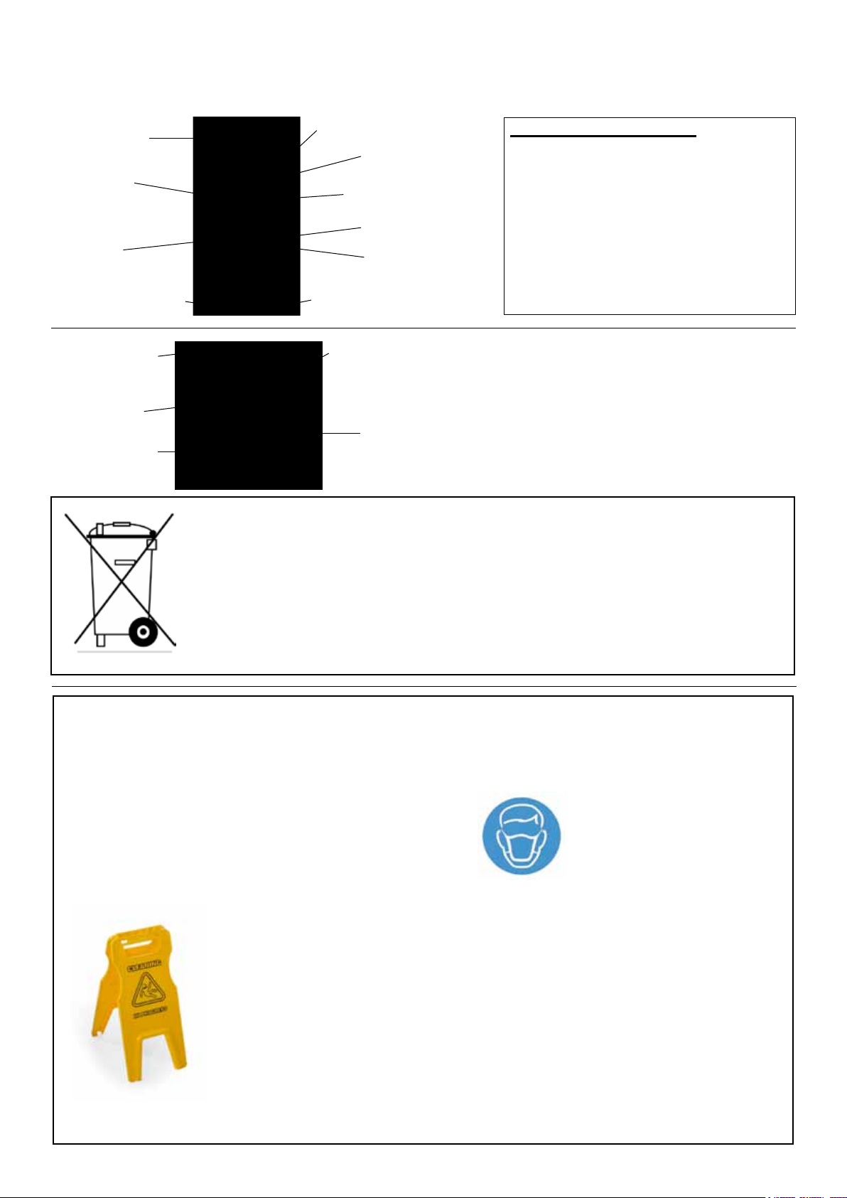
Rating label/ Personal Protective Equipment/ Recycling
Company name
and address
Power rating
Gradient %
Yr/Wk/Seriial number
Machine
Description
Noise level
Whole body
vibration
Machine Description
Voltage
Charging voltage range
/ Frequency
WEEE logo
CE mark
Weight (includes average
75Kg operator and full tanks)
Weight (includes average
75Kg operator and full tanks)
Hand Arm Vibration
Scrubber drier accessories and packaging should be sorted for
Environmental- Friendly recycling.
Only for EU countries.
Do not dispose of scrubber drier into household waste.
According to the European directive 2002/96/EC on Waste Electrical Electronic Equipment
(WEEE) and its incorporation into national law.
Scrubber driers that are no longer suitable for use must be separated, collected and sent for
recovery in an environmentally- friendly manner.
Safety Critical Components
Charging Leads: Ho5VV-F x 1mm2 x 3 Core
Motor Wheel
& modied brake lead assmenbly (321450)
PG Controller (208169)
Battery Charger (230V )
(115V )
PPE
(Personal Protective Equipment)
that maybe required for certain operations.
Ear Protection Safety Footwear Safety Hat Safety Gloves Face Mask Eye Protection Protective Clothing
Hi Vis Jacket
NOTE:
A risk assessment should be conducted
to determine which PPE should be worn
Caution Floorsign
6
233890 05/11 (A03)
Page 7
Quick Set Up Guide
Please read before commencing any operation.
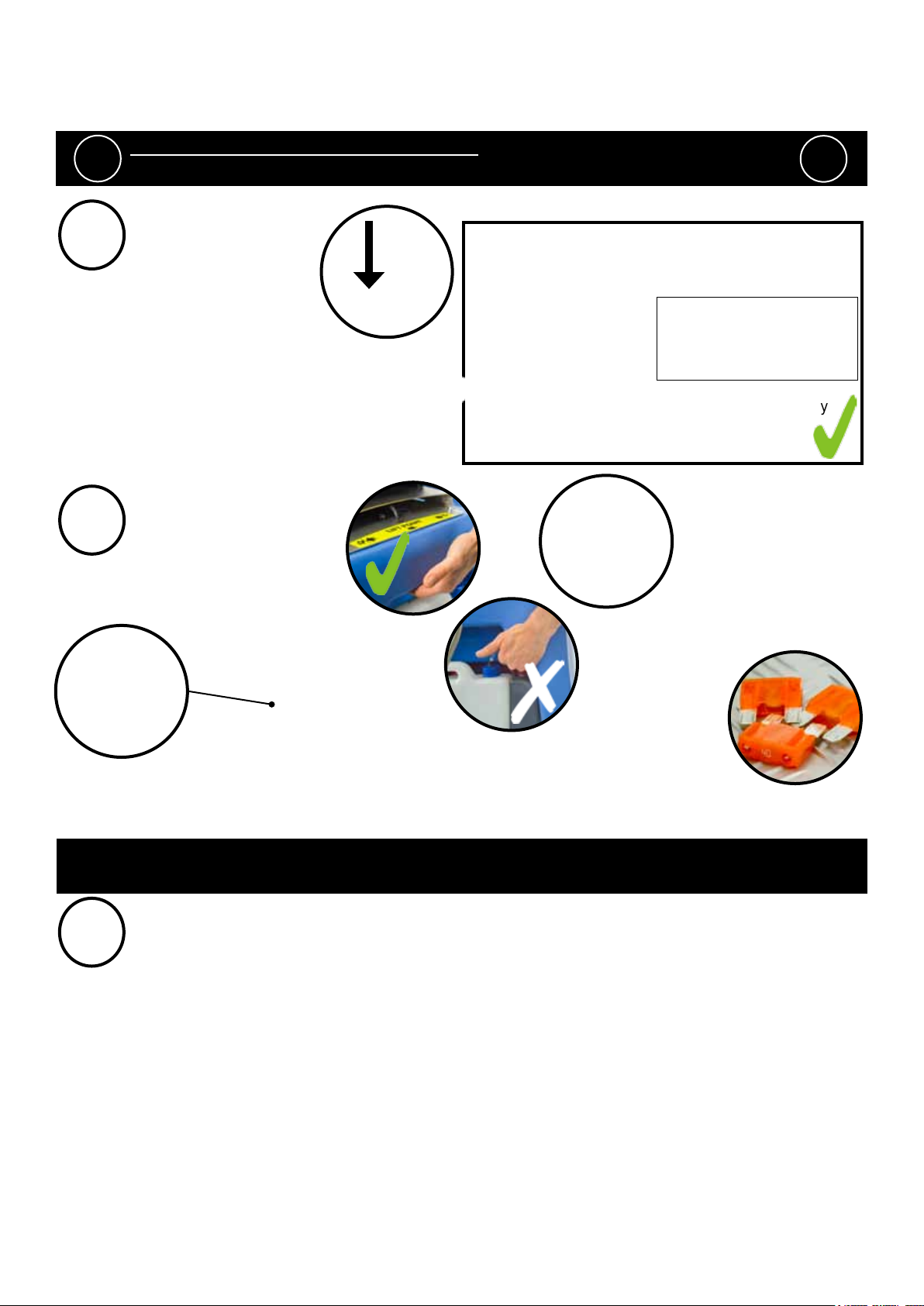
After the removal of all the packaging, carefully open and check the contents of the start up pack (g.1).
!
1
2
!
Contents:
1 x Operator Manual
2 x Battery charging lead
2 x Keys
4 x 40 amp fuses (1 x spare)
TTV678/300T
or
5 x 30 amp (1 x spare)
TTV678/400T
2 x Side pod skirts
1 x Brake disengage key
1 x Maxi fuse-puller
Fig.1
Fig.2a
Lift top tank assembly to reveal battery compartment
Always lift between points as illustrated to ensure personal safety (g.1a)
Fit battery fuses (contained in start-up pack) into the battery fuse holders as illustrated (g.2).
Remove transit block from pallet (g 2a).
Note: Ensure that no metal objects come into contact with battery terminals while the batteries are exposed.
When inserting the rst fuse you may notice a spark, this is normal.
Fig.1a
Fig.2
3
Insert key (g.3) into ignition and turn quarter-turn clockwise to the ‘ON’ position.
Ensure that the forward/reverse switch is set to forward (g.4).
Depress accelerator pedal with right foot and slowly drive machine off of the pallet
using the ramp provided (g.5).
Note: The seat is tted with a pressure sensor that disables the machine until an operator
is seated.
When the machine is removed and in a safe position, turn key back to the off position (g.6).
233890 05/11 (A03)
Fig.6
7
Page 8
Machine Set Up
ALWAYS ENSURE THAT THE MACHINE IS SWITCHED OFF
!
Fitting the side pod skirts
Fig.6a Fig.6b
To t the side pod skirts, rst remove the steel retaining strip already tted to the pod (g 6a).
Align the steel retaining strip within the locating grooves of the rubber skirt and ret using existing screws (g 6b)
Periodically the side skirts should be examined and checked for wear and damage. Replace as shown above.
BEFORE MAKING ANY ADJUSTMENTS
!
Fitting the oor-tool
Fig.9
!
Fig.7
Lower the oor-tool arm by moving the release lever to the upper position (g. 7)
Push oor-tool onto the holder and secure with the easy-t securing pin (g 8)
Push waste collection pipe onto the oor-tool; ensure a tight t (g 9)
Note: Raise oor-tool again before driving to the cleaning area (g.9a)
8
233890 05/11 (A03)
Fig.8 Fig.9a
Page 9

Machine Set Up
Fitting the brushes
Fig.10 Fig.11
Featuring the new OBS (Octagonal Brush System);
the brushes simply push-t up onto the chucks
making tting and removal a simple process.
Pull the side pod adjustment lever and set to the top position (g 10).
The side pod will now pull open (g 11).
Fit middle brush rst (brushes will click-t onto the OBS drive chuck)
Fit outer brush next on both sides.
Close side pod and while keeping the side pod pushed in, set to
appropriate width (see setting the width) (g.12)
Safety gloves are recommended for the changing of used brushes.
Fig.12
Owning the TTV-678 ride on scrubber drier is like having 3 machines in one.
With three width-settings the operator can quickly adapt the machine to any cleaning situation;
without the need for any tools. The machine can be set to clean anything from a narrow corridor to
a large warehouse. The TTV-678 is a totally versatile machine.
233890 05/11 (A03)
9
Page 10
Machine Set Up
Setting the width adjustment
First push the side pod in (see g.13), then pull the side pod adjustment lever
and set it to one of the three width-settings (see g.13a) Repeat the
operation on both sides.
Fig.13a
650mm 750mm 850mm
Filling the clean water tank
Fig.13
The TTV-678 is equipped with a large capacity 110 litre clean-water tank allowing, for large areas to be covered in
a single ll.
Fig.14 Fig.15 Fig.16
To ll the clean-water tank, lift the cover ap (g.14) to expose the ller cap.
Unscrew the ller cap (g.15) and ll the tank using a hose (g.16) or preferred method.
Note: Great care must be taken to ensure that contaminants (leaves, hair, dirt, etc.) are not allowed to enter the
clean-water tank during the lling process. If using a bucket or similar, ensure it is always clean and free from
debris.
10
Fill-level indicator
The water level in the clean water tank can be measured using the
scale on the rear of the machine (g.16a).
Fig.16a
233890 05/11 (A03)
Page 11

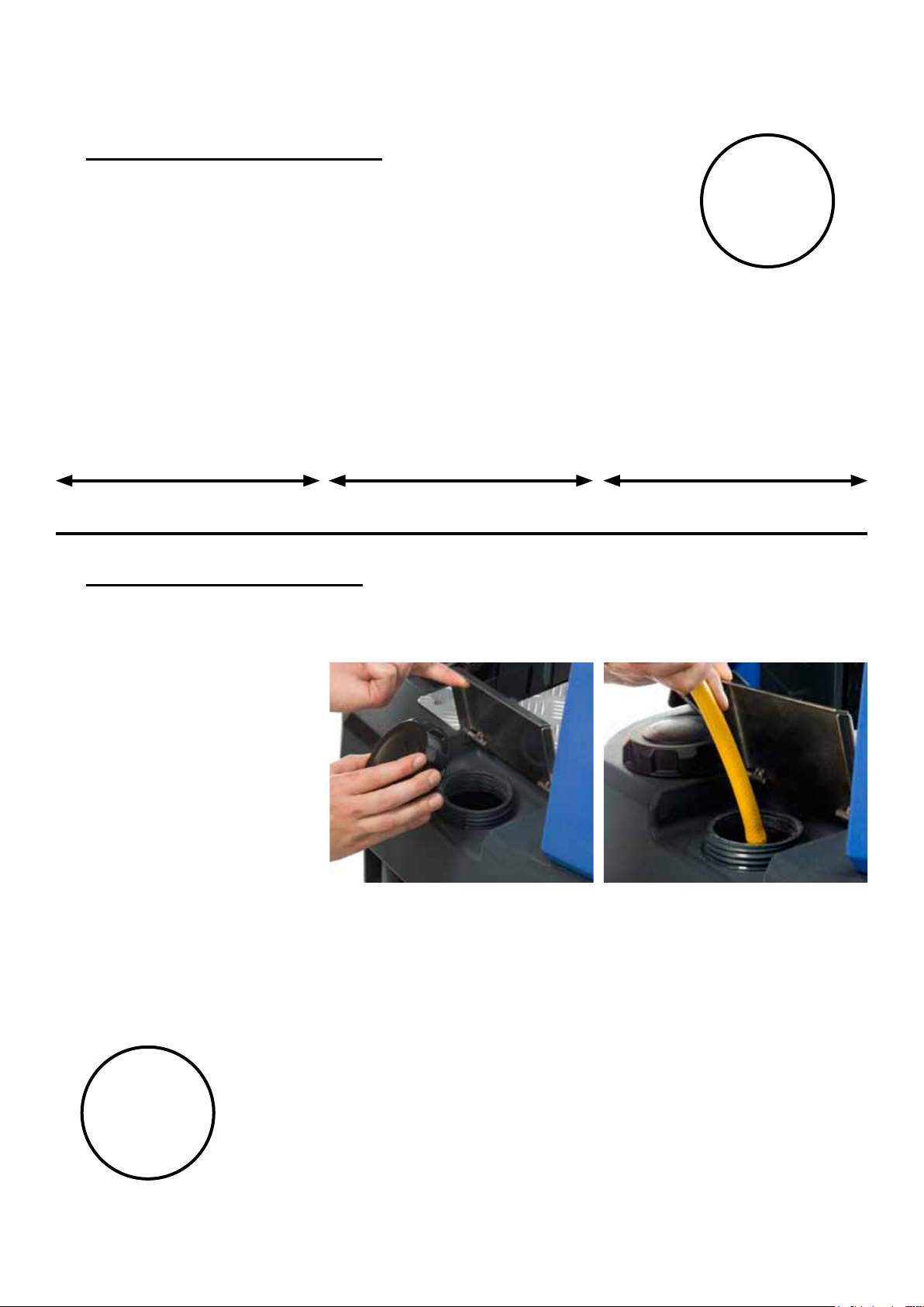
When handling and mixing chemicals.
!
Chemical dosing System
The TTV-678 ride-on scrubber drier has an optional automatic chemical-dosing system.
Simply ll the 4 litre chemical dosing bottle and the machine will deliver the correct mix ratio as set by the operator,
depending on the oor and cleaning conditions.
Always ensure that chemical manufacturers safety guidlines are followed.
Only use chemicals recomended for use in auto scrubber-driers.
!
Fig.18 Fig.19 Fig.20
To ll the chemical-dosing bottle, rst lift up the waste-water tank (g. 18), remove the dosing bottle, unscrew the
bottle cap (g.19) and ll with appropriate cleaning chemical. Replace bottle cap, ret dosing bottle (g.20)
and carefully lower waste-water tank.
After use, ensure the chemical dosing tank is emptied, cleaned and relled with clean water.
The dosing pipes also need to be cleaned and ushed through with clean water for at least 60 seconds
Note: always ensure that the waste-water tank is empty before lifting.
Important
Do not operate machine unless the Operator Manual has been read and fully understood.
!
The machine is now ready to be driven to the cleaning site (see section 3 of quick set-up guide if necessary).
!
Before performing the cleaning operation, place-out appropriate warning signs and sweep or dust-mop the oor
233890 05/11 (A03)
11
Page 12

Lowering the brush deck
Fig.20 Fig.21 Fig.22
Machine Set Up
After preparing the oor (see previous section), we are now ready to set the controls to suit the cleaning conditions.
Before any settings can be applied, ensure the brush deck is lowered.
While depressing left-hand foot pedal (see g.20), press down the release lever (see g.21) and gently release
the foot pedal to lower the brush deck (see g.22).
Note: If the brush width has not been set, see ‘Setting the width adjustment’ on page 8 before proceeding.
Lowering the oor tool
Fig.23
Lower the oor-tool by moving the release lever to the upper position (g. 23)
NOTE: The machine will not reverse while the oor-tool is in the lowered position - ‘Causes the battery indicator to ash’.
12
233890 05/11 (A03)
Page 13

Adjusting the seat
Fig.24
Sitting in the driving position, adjust the seat forwards or backwards as necessary by using the lever
found on the left-hand side (see g.24).
Note: The seat is tted with a pressure sensor that disables the machine until an operator is seated.
Setting the cleaning controls
Insert the key into the ignition and quarter-turn it clockwise to the ‘ON’ position.
The battery charge-level indicator will illuminate.
Set automatic Chemical Dosing Mix as required, depending on oor type and level of soiling.
75:1
50:1
25:1
100:1
Set desired Brush Speed as required, depending on oor type and level of soiling.
Set Water Flow Rate as required, depending on oor type and level of soiling
0.25 gpm
0.5 gpm
233890 05/11 (A03)
0.75 gpm
1.0 gpm
13
Page 14

Setting the operator pre-set buttons
Settings can be stored using one of the three pre-set store buttons (S1/S2/S3).
Once settings are entered (chemical dose, brush speed and water-ow), press and hold
one of the three pre-set store buttons, a light will ash then remain constant; your settings
are now saved.
This facility can be re-set as often as you wish by simply following the steps above.
Machine Operation
S1 S2
Cleaning Speed setting (CS). When this button is activated the speed is restricted to
3.5km/hr maximum even with the accelerator pedal fully depressed. This is ideal for long
cleaning periods. Once this pre-set button is switched-off, the machine will operate at up
to a maximum speed of 7.0km/hr.
Waste water tank ll level warning light
When the waste water-tank becomes full, a red warning light will illuminate on the
operator control panel (as illustrated) and the vacuum motor will stop automatically
after 5 seconds . The waste-water tank requires emptying (see page 16).
S3
CS
Brush pressure / Load adjustment
The machine is equipped with a brush-pressure load-warning system.
If the brush load increases due to changing oor types, the pressure can be adjusted
manually by the operator using the adjuster knob found on the left hand side of the control
column.
Turn it anti-clockwise to decrease load on the brushes and clockwise
to increase load/pressure on the brushes. (see g.25).
NOTE: The run-time of the machine may decrease
if the load on the brushes is increased
14
233890 05/11 (A03)
Fig.25
Page 15

Emergency-stop button and horn
The TTV-678 is equipped with an electronic braking system.
Fig.26
Simply lift your foot from the accelerator and the machine will stop.
In an emergency, strike the emergency-stop isolator button
The machine will be disabled.
To reset, turn isolator button clockwise (see g.26).
After re-setting the emergency stop button, to restart the
machine ,turn the ignition key to the off then the on
position again.
The horn is located on the right-hand side of the operator
control panel (see g.26a)
Fig.26a
ALWAYS ENSURE THAT THE FLOOR IS PRE-SWEPT
! !
AND RELEVANT SAFETY SIGNS ARE DISPLAYED.
Machine in use
To operate, select forward or reverse, press the accelerator
pedal. Vacuum pick-up, water-ow and chemical-dose will
turn on automatically and the machine will move forward.
The clean water / chemical mix is dispersed evenly via
‘THRU- FEED’ scrubbing brushes.
The waste water is then retrieved by the suction oor-tool
(see g.27). Overlap each scrubbing path by 10cm to ensure
an even clean.
Do not operate the machine on inclines that exceed 11%.
Fig.27
Fig.28
NOTE: Care must be taken to reduce speed when
cornering or when manoeuvring around obstacles
If streaking occurs wipe oor-tool blades clean (see g.28).
On heavily soiled oors use a ‘double scrub’ technique.
First pre-scrub the oor with the oor-tool in the raised position,
allow the chemical time to work then scrub the area
a second time with the oor-tool lowered.
233890 05/11 (A03)
15
Page 16

Breakaway oor-tool
The oor-tool design incorporates a breakaway feature allowing it to safely
disengage from its mounting should it become caught on an obstruction.
(See g.29)
Fig.29
To attach the blade to its holder, rst loosen the retaining knobs on the oor-tool body and
slide onto the holding bracket.
Tighten retaining knobs to nger tight.
(See g.30)
Fig.30
Machine Operation
Off-Aisle Cleaning Kit (Optional Extra Accessory)606182
The optional off-aisle cleaning kit gives added exibility to the operator. The kit can
be used to clean hard to reach/inaccessible areas. Press the blue auxiliary switch
on the dashboard (see g.31); ensure the oor tool is in the lowered position (see g.31.a)
so only the vacuum will operate and all other functions on the machine will become disabled.
If oor-tool is in the raised position the vacuum will not operate and the control panel lights
will ash. The machine will need to be reset by simply turning the ignition key off and
on again.
Fig.31
Fig.31a
Off-Aisle Accessory Kit
(Optional) (606182)
16
233890 05/11 (A03)
Page 17

Machine Cleaning
ALWAYS ENSURE THAT THE MACHINE IS SWITCHED
! !
OFF PRIOR TO ANY MAINTENANCE.
After use, empty waste-water tank using emptying hose
and ush-out with clean water.
Next remove oor-tool vacuum hose and ush-out
with clean water.
Next empty clean water tank, using emptying hose
and again ush-out with clean water.
B
C
A
B
C
Before removing separator, rst pull-off connected hoses.
Whilst pressing in the separator toggles, remove hood and rinse using clean water.
The hood also has a sealing-rubber which should be examined at every clean-down.
A
Remove white lter and rinse using clean water, and ret.
IMPORTANT:
Never use the machine without the recommended lter as it may cause damage to
the machine.
Remove debris basket lter and rinse using clean water, and ret.
IMPORTANT:
If the debris basket is allowed to become clogged, vacuum performance can deteriorate.
The clean-water tank lter is located to the rear of the battery compartment, and should
be checked at regular intervals. Lift white plug and remove white lter, rinse and ret.
Ensure tank has been emptied and care is taken when working in the vicinity of batteries.
NOTE: ANY SPILLS SHOULD BE WIPED-UP BEFORE TANK IS LOWERED.
233890 05/11 (A03)
17
Page 18

Machine Cleaning
ALWAYS ENSURE THAT THE MACHINE IS
! !
The oor-tool
SWITCHED OFF PRIOR TO CLEANING.
Fig.32
To clean the oor-tool, remove securing-pin and pull-free from the holder (see g.31).
Rinse the oor-tool assembly with clean water and ret.
Fig.34
Periodically the oor-tool blades should be examined and checked for wear and damage.
The blade removal is easy. Simply start by removing the four retaining pins (see g.33), turn the
oor-tool over and separate the blade carrier from the body (see g.34).Peel away the blades from their locating lugs
(see g.35) and examine or renew as required.
Replacement is a reversal of the removal process.
Fig.35
Fig.33
Floor-tool overview
1. Floor-tool main body
2. Rear blade
3. Blade carrier
4. Front blade (slotted)
5. Retaining pins x 4
18
1
2
3
4
233890 05/11 (A03)
5
Page 19

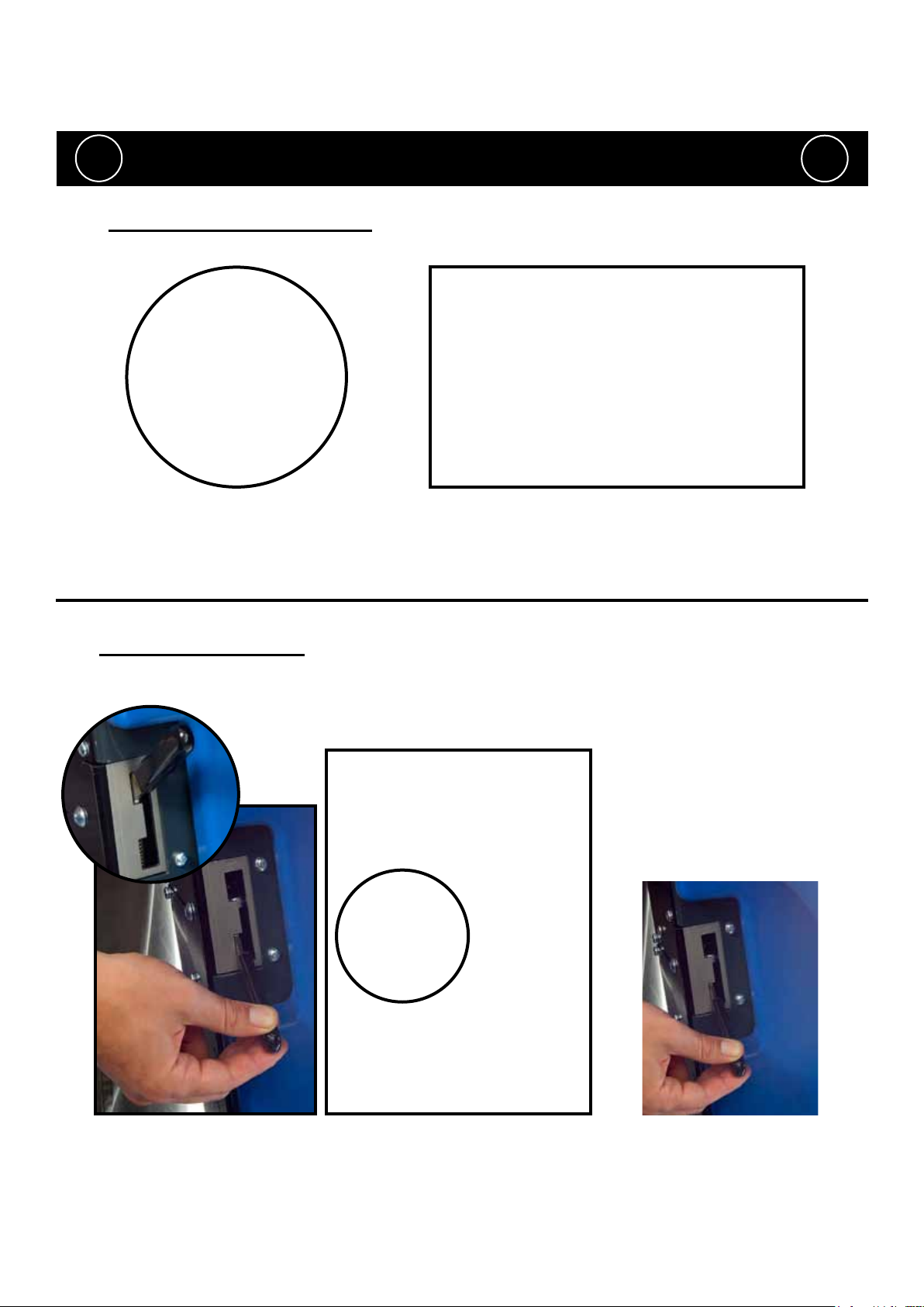
Machine Charging
ALWAYS ENSURE THAT THE MACHINE IS
! !
The battery meter displays the charge level of the batteries; when fully charged,
all meter lights are illuminated (see g 36).
SWITCHED OFF PRIOR TO CHARGING.
Fig.36
Fig.36a
As the machine is used and the batteries are discharged, the meter lights will go out from
right to left.
If the battery-charge level is allowed to discharge to the point that only the red light remains
illuminated, the operator must consider charging the machine.
If the battery-charge level is allowed to discharge to the point that only one red light remains
illuminated (and begins to ash), all cleaning functions will automatically be disabled and
the operator should drive the machine straight to a suitable charge point.
The large capacity gel batteries are sealed for life and are totally maintenance free.
The on-board charger automatically monitors the charging process and will switch off
when the batteries are fully charged.
The machine charging point is located under the top tank. Always ensure the top tank is
empty before attempting to lift it (see g.37).
Fig.37
Fig.38
Fig.39
Insert the charging lead required for your country (see start up pack) into the charging point
and connect to a suitable power supply (see g.38).
Once mains power is connected the red charging indicator will illuminate.
To ensure a full charge, the machine should be left for a period of 8-12hrs.
Once fully charged, disconnect the charging lead from both the power supply and
the machine and lower the tank back into position as described earlier (see g 1a,page 6).
233890 05/11 (A03)
19
Page 20

Free-Wheel Function
ALWAYS ENSURE THAT THE MACHINE IS ON LEVEL
GROUND BEFORE DISENGAGING BRAKE ARM.
! !
The TTV-678 is equipped with a free-wheel function that will enable the operator to move / tow the machine.
NEVER DISENGAGE THE BRAKE WHEN THE MACHINE
IS ON A SLOPE / GRADIENT
NEVER TOW THE MACHINE WITH THE BRAKE ENGAGED
The motor brake is disengaged by opening the
brake arm on the side of the drive wheel (see g.40).
Fig.40
Fig.41
Fig.42
Your start-up kit includes a brake drive disengage key (329945, see g.41)
which can be inserted between the brake arm and drive housing
(see g.42).
Once the key has been inserted (see g.42)
the motor brake will be fully disengaged.
The machine will now be in full free-wheel mode.
20
Fig.43
When towing the machine ensure that a suitable tow bar is used.
Care must be taken when towing; maximum speed to be no more than 7kmh.
The machine can be towed from the front bar as indicated (see g.43).
WARNING!
WHEN THE BRAKE IS DISENGAGED THE MACHINE IS IN FREE-WHEEL
MODE AND HAS NO BRAKE FACILITY, THEREFORE A RIGID TOW BAR
MUST BE USED IF TOWING.
Remember to remove the brake disengage key when you reach your
nal destination / before using the machine.
233890 05/11 (A03)
Page 21

Battery Care
To ensure your machine remains at its maximum efciency and prolong your battery life, please follow
the simple steps below:
Under normal daily usage:
Recharge batteries after each use regardless of machine operation time
(see page 19)
Showing location of Viewing panel for charging-light sequence.
Yellow:- Charging Normally, 23 hours MAX
Yellow Flashing:- Charging Finished, (Trickle Charging)
Green:- Fully Charged
Red:- Remove Mains Supply
Failure of charger prole – corrective action replace faulty battery
Charging stopped. time out timer expired (27hrs) corrective action
replace faulty batteries
Internal charger failure – corrective action replace charger
Over temperature – corrective actions ensure charger ventilation
slot are free of debris and ventilation channel has no restrictions.
Recharge the machine fully after its last use. Do not leave the machine in a discharged state.
233890 05/11 (A03)
21
Page 22

Under abnormal use; i.e. leaving the machine without charging
for a period of time - we advise that you
follow these steps:
If the machine will be standing unused for a period of 30 days
or more, then batteries must be fully charged and battery fuses
removed using the Maxi fuse-puller provided, prior to this period.
Batteries should be recharged every three months.
Charge fully the day before you start using the machine again.
Notes.
.......................................................
.......................................................
.......................................................
.......................................................
.......................................................
.......................................................
.......................................................
.......................................................
.......................................................
.......................................................
.......................................................
.......................................................
.......................................................
.......................................................
.......................................................
.......................................................
.......................................................
22
233890 05/11 (A03)
Page 23

Trouble-Shooting
PROBLEM CAUSE SOLUTION
Machine will not operate Missing or blown fuses
Key in the ‘OFF’ position
Low battery charge
Machine isolator button in ‘OFF’ mode
Machine is connected and charging
Vacuum will not operate Floor tool in raised position
Waste water tank full
Poor water pick-up Waste-water tank full
Clogged / blocked vacuum hose
Loose hose connections
Debris basket lter cloogged/blocked
Separator lter clogged / blocked
Poor separator seal
Damaged separator seal
Damaged / split vacuum hose
Damaged oor-tool blades
Low battery charge
No brush / scrub function No brushes tted
Brush deck raised
Little or no water ow Clean-water tank empty
Clean-water tank lter blocked/ clogged
Incorrect water ow setting
Brush deck raised
Little or no dosing solution ow Chemical dosing tank empty
incorrect dosing ow setting
Machine just ‘stops’ while
operating
Machine will not operate in reverse
To much load on the brush system Reset the machine using the key and
Floortool in lowered position
‘Causes Battery Indicator to Flash’
Fit or replace fuse (page 7)
Turn key to ‘ON’ position (page 7)
Charge batteries (page 19)
Reset isolator (page 15)
Take off charge (page 19)
Lower oor-tool (page 12)
Empty waste water tank (page 17)
Empty waste-water tank (page 17)
Remove and clean (page 17)
Push tight connections (page 16)
Remove and clean (page 17)
Remove and clean (Page 17)
Clean and ret (page 17)
Renew (contact service dept)
Renew (contact service dept)
Renew (contact service dept)
Recharge batteries (page 19)
Check and t (page 9)
Lower brush deck (page 12)
Fill clean-water tank (page 10)
Remove and clean (17)
Adjust as desired (Page 13)
Lower brush deck (page 12)
Fill dosing-tank (page 11)
Adjust as desired (page 13)
decrease the brush load to best suit
the oor type (page 14)
Raise oortool (page 12)
Diagnostic software is available via your service engineer.
Failure to rectify the problem or in the event of a breakdown contact your
Numatic dealer or the Numatic Technical helpline +44 (0)1460 269268
233890 05/11 (A03)
23
Page 24

Persists.
* Charge batteries immediately.
* Tighten loose connections and replace dam-
aged components.
* Replace batteries as required.
* Replace charger.
* Check when machine last charged.
* Switch OFF the machine.
* Remove Fuses.
* Check connections to batteries, charger and
fuses for loose wires or screws.
* Check each battery Voltage individually to detect
Contact Service Agent.
* Cycle key switch to resume normal opera-
tion.
* Tighten loose connections and replace dam-
aged components.
defect unit 10.5V min.
* Check battery voltage and charge current.
ensuring charger red fault light is extinguished.
free from debris.
* Cycle Key switch to resume normal operation.
If the above fails then: Switch machine off.
Check connections and harness between drive
motor and controller.
* Change brush , adjust brush speed and
reduce
pressure by turining adjustment knob anti-
clockwise.
* Replace effected motor or wiring.
* Brush type suitable for oor surface.
“ Cycle Key switch to resume normal operation.
* If the above fails then: Switch off machine.
* Check brush motor for damage.
* Check brush motors turn freely.
* Cycle key switch to resume normal operation.
* If the above fails then.
* Switch machine off.
* Check connections and harness between Brush
* Rectify wiring fault found.
Motor and controller.
* Check BRUSH Motor connections block under-
neath chassis , behind mud guard for loose wires
and loose screws.
* Cycle key switch to resume normal operation.
water/detergent pump wiring conguration.
* Tighten loose connections and replace
damaged components - check exhaust clean
if necessary.
* If the above fails then:
* Switch off machine.
* Check for loose or damaged wiring and
connections between Vac motor and controller.
* Cycle key switch to resume normal operation.
* Operating time severely reduced
or machine will not operate.
* Brake engaged no movement. * Did machine fail on incline. Check traction wheel
Trouble Shooting
* Possible bad connection between batteries,
controller, charger or fuses caused by loose
connections ,
damaged wiring , water ingress.
* Not accepting charge due to faulty battery/cell.
* Charger not functioning.
* Batteries voltage low. * Batteries not been charged.
a load.
* Traction drive overload. * Traction drive over current trip due to too high
* Traction drive is disconnected or has bad con-
nection due to wiring or
connectors becoming damaged, loose or cor-
roded due to water ingress.
* Intermittent brush trip.
* Brush Motor doesn’t run or runs
intermittently.
Rough oor surface.
Brush motor has failed or is
damaged..
Brush motor bad connection.
Brush motor over current trip has
occurred.
* Vac motor will not operate. “ Cycle Key switch to resume normal operation.
* Wiring between Vac motor and
Controller is damaged, wiring is loose or wiring
connections are loose, possibly wire has come
out of a
connection block - block exhaust.
* Spare Solenoid connection trip. * System has been incorrectly rewired. * Machine will not operate. * Refer to wiring diagram and check the solenoid/
* Vac Motor is disconnected, has failed
open circuit, has a bad
connection or water ingress -
temperature trip activated.
24
Number of bars ashing on display Fault Possible Cause Effect on Product Investigate the Following Action Required If Fault
Sleeping/rest mode: Battery indicator ashes every 5 seconds indicates machine has been idle for more than 20 minutes. Vario functions disabled cycle key switch!
* 1 Bar ashes continuously
* 2 Bars Flash continuously.
3 Bars Flash continuously.
233890 05/11 (A03)
* 4 Bars Flash twice with pause.
* 4 Bars Flash once with pause. * System trip. * System failure. * Machine will not operate. * Replace controller.
* 5 Bars ash continuously.
Page 25

Persists.
Contact Service Agent.
* Operator to be trained.
seat switch being activated. Ensure rm contact
with seat by operator at all times while accelerator
* Machine will not drive. * Ensure accelerator pedal is not activated without
* Reset emergency stop button. Switch off aisle
vac and raise oor tool.
* Cycle key switch to resume normal operation.
* Cycle key switch to resume normal operation.
is pressed.
activated and off aisle vac switch is in off position
with oor tool raised.
* Machine will not drive. * Ensure emergency Stop button has not been
* Cycle Key switch to resume normal operation.
* Check wiring and connections to device. * Replace damaged components.
in accordance with safety require-
ments.
* Cycle Key switch to resume normal operation.
* Cycle Key switch to resume normal operation.
* Check wiring and connections to pump. * Replace damaged components.
* Check wiring and connections to pump. * Replace damaged components.
heads.
to cleaning head.
* Cycle Key switch to resume normal operation.
* Replace damaged components.
* Cycle Key switch to resume normal operation.
* Check battery wiring, trio drive and motor
connections.
* Possible long term damage to
controller if fault persists.
* Cycle Key switch to resume normal
operation .
* Correct wiring.
* Cycle Key switch to resume normal operation
or depressed during switch on of Vario.
* Machine will not operate. * Remove object and ensure pedal is not jammed
attention to wires p2/03 and p2/10.
* Replace/clean damaged components.
* Replace/clean damaged components.
machine by brushes ensuring microswitch is clear
of debris.
handle.
Number of bars ashing on display Fault Possible Cause Effect on Product Investigate the Following Action Required If Fault
seat switch being activated (nobody on seat)
Or seat switch momentarily deactivated while
accelerator pedal being activated during forward
/ reverse operation.
* Inadvertent pressing of emergency stop or
activation of off-aisle cleaning mode.
* Control system is Inhibiting drive. * Faulty controller. * Machine will not operate. * Check controller for water damage. * Replace controller.
* 6 Bars ash continuously.
* Accelerator pedal trip. * Accelerator pedal being activated without
*7 Bars ash once with pause
* Off aisle cleaning activated with oor
tool raised.
* 7 Bars ash twice with pause. “ Emergency stop has been activated.
* 7 Bars ash 3 times with pause. * Vac Motor system short circuit. * Vac motor wiring fault / motor fault. * Vac motor will not operate. * Check vacuum motor and wiring * Replace motor and any damaged wiring.
* Control system trip. * Seat switch failure. * Machine does not operate. * Check seat switch wiring. * Replace wiring as required.
* 8 Bars ash continuously.
* Flashing beacon failure to operate. * Beacon short circuit. * Flashing beacon does not operate
* 9 Bars ash once with pause.
233890 05/11 (A03)
* 9 Bars ash 3 times with pause. * Water pump failure to operate. * Failure of pump or wiring short circuit. * No water supplied to cleaning
* 9 Bars ash 4 times with pause. * Detergent pump failure to operate. * Failure of pump or wiring short circuit. * No detergent supplied in water mix
* Battery and motor connections may have
become loose.
* Supply voltage to controller has
exceeded 40 volts.
* 9 Bars ash 5 times with pause. * Solenoid brake circuit failure. * Failure of solenoid or wiring. * Machine will not move. * Check wiring and connections to brake. * Replace damaged components.
* 10 bars ash continuously
* Foot or object on pedal during switch on or
possible jamming of pedal.
* Accelerator pedal movement
detected during Vario start up se-
quence (partially pressed or jammed).
* Bars cycle up and down
continuously (from 1 to 10 and 10
back to 1) and repeats.
* Machine inhibit. * Controller/harness incorrectly wired. * Machine will not operate. * Check controller and harness wiring with special
* Bars cycle from 1 to 10
continuously and repeats.
* Microswitch failure. * Brushes will not operate correctly. * Check wiring and microswitch on underside of
* No indication on display. * Brush motors continuously either off
* No indication on display. * Horn and beacon failure. * Replace 20 Amp fuse (If this doesn’t x fault replace horn or beacon)
* Microswitch failure. * Vacuum will not operate correctly. * Check wiring and microswitchs behind oor tool
or on while in transport mode.
or on.
* No indication on display. * VAC motor continuously either off
25
Page 26

Recommended Spare Parts
LINATEX BLADES:
208203 - Linatex Blade (650mm) (Rear)
208201 - Linatex Blade (650mm) (Front)
606196 - Blade Set (650mm)
208194 - Linatex Blade (850mm) (Front)
208196 - Linatex Blade (850mm) (Rear)
606198 - Blade Set (850)
FLOOr TOOLS:
606216 - TTV Squeeqee Assembly (650mm)
606218 - TTV Squeegee Assembly (850mm)
ruBBEr SIDE SkIrTS:
206947 - Splash Skirt
329843 - Splash Skirt Fixing Strap
BruShES:
606152 - Polysbcrub Brush
606151 - Nyloscrub Brush
606153 - LongLife Brush
606155 - Pad Drive Brush
GENErAL rEquESTED SpArES:
229987 - Blade Holder Moulding (650mm)
229988 - Blade Holder Moulding (850mm)
206953 - Floor Tool Detent Pins
206951 - Floor Tool Quick Release Knobs
208167 - Spare Keys
208163 - Seat Pressure Switch
208164 - Amber Lens
208165 - Bulb
208166 - Mounting Ring
206439 - Basket Filter
221047 - 40A Battery Fuses (TTV 678/ 300T)
230104 - 30A Battery Fuses (TTV 678/ 400T)
208191 - Vac Hose
208192 - Suction Hose
208042 - Gas Strut
229834 - RH Side Buffer
229835 - LH Side Buffer
303809 - Chuck Assembly
206933 - Forward / Reverse Switch
208077 - Bottom Tank Filler
206944 - Top Tank Float Switch
206939 - Rear Wheels
208048 - Display Panel Membrane
321458 - Brush Motor (Leads Extended 100mm)
321459 - Brush Motor (Leads Extended 400mm)
321460 - Brush Motor (Leads Extended 300mm)
208169 - PG Controller
321406 - Water Pump
321417 - Dosing Pump
205112 - Batteries
321450 - Amer Drive Wheel Unit
208118 - Non return Valve Assembly
219452 - 100mm Hole Plug
303880 - Vac Motor
208104 - Steering Knob
606167 - Batteries & Cabling for Additional 2 Battery Kit
206959 - Squeegee Lifting Cable
606168 - Off Aisle Accessory Kit
329945 - Brake Disengage Key
DrIVE MOTOr SpArE pArTS:
208145 - Wheel (Tyre)
208146 - Armature Brush
208147 - Motor Brush
208148 - Friction Disc
208149 - Rubber Gasket
321506 - Brake
208151 - Pinion
208152 - Steering Chain
208153 - Steering Chain Master Link
OpTIONAL SpArES:
606200 - Vacuum Silencer
26
233890 05/11 (A03)
Page 27

Notes
..............................................................................
..............................................................................
..............................................................................
..............................................................................
..............................................................................
..............................................................................
..............................................................................
..............................................................................
..............................................................................
..............................................................................
..............................................................................
..............................................................................
..............................................................................
..............................................................................
..............................................................................
..............................................................................
..............................................................................
..............................................................................
..............................................................................
..............................................................................
..............................................................................
..............................................................................
..............................................................................
..............................................................................
..............................................................................
233890 05/11 (A03)
27
Page 28

WD - 0359 (A12) 11/03/2011
28
233890 05/11 (A03)
Page 29

233890 05/11 (A03)
29
Page 30

Specications
Brush
Motors
3 x 24V
400W
Vac Motor Power
24V 400W
6 x 12V =
300Ahr
Model - TTV678-300T
Noise
Max decibel
level at 1 meter
72dB (A) (ISO
3744)
Uncertainty: 0.2dB(A)
Time
Traction
Drive
Transit
Speed
Cleaning
Speed
Climbing
Gradient
3.5 hrs 600W 7.0km/h 3.5km/h 11%
Scrub
Widths
650mm
750mm
850mm
Brush
Speed
50/100
150/200
rpm
Brush
Motors
3 x 24V
400W
Brush
Speed
50/100
150/200
rpm
Water
Capacity
31.7
gallon
Nuchem
Capacity
1 gallon
Vac Motor Power
24V 400W
Water
Capacity
31.7
gallon
Nuchem
Capacity
1 gallon
Water
Flow rate
1.00 gpm
0.75 gpm
0.50 gpm
0.25 gpm
8 x 12V =
400Ahr
Water
Flow rate
1.00 gpm
0.75 gpm
0.50 gpm
0.25 gpm
Nuchem
Mix
25:1
50:1
75:1
100:1
Model - TTV678-400T
Noise
Max decibel
level at 1 meter
72dB (A) (ISO
3744)
Uncertainty: 0.2dB(A)
Nuchem
Mix
25:1
50:1
75:1
100:1
Gross
Weigt
(Full)
Gross Weight
(Full)
Plus 75KG
Operator
620Kg 695Kg
Time
Traction
Drive
Hand Arm
Vibration
Measurement
2.1m/s
(BS EN150 5349)
Uncertainty 1%
Transit
Cleaning
Speed
Whole Body
Vibration
Measuremen
0.525m/s
(ISO 2631-1)
Uncertainty 1%
Speed
4.5 hrs 600W 7.0km/h 3.5km/h 11%
Gross
Weigt
(Full)
Gross Weight
(Full)
Plus 75KG
Operator
686Kg 761Kg
Hand Arm
Vibration
Measurement
2.1m/s
(BS EN150 5349)
Uncertainty 1%
Whole Body
Vibration
Measuremen
0.525m/s
(ISO 2631-1)
Uncertainty 1%
Climbing
Gradient
Dimensions
Hx1425mm
Lx1676mm
Wx1054mm
Scrub
Widths
650mm
750mm
850mm
Dimensions
Hx1425mm
Lx1676mm
Wx1054mm
30
233890 05/11 (A03)
Page 31

233890 05/11 (A03)
31
Page 32

32
233890 05/11 (A03)
 Loading...