

Page 1

Owner Instructions
T T B 516
(TTB 1840)
Mode d’emploi
Original Instructions
Warning! Read instructions before using the machine.
Attention
Lisez la notice avant d’utiliser la machine.
Page 2

!
Before continuing, please refer to Quick Set Up Guide on Page 8
!
Index
Machine overview
Control panel overview
Rating label / Personal Protective Equipment / Recycling
Safety Precautions
Quick set-up guide
Machine set-up
Fitting the brushes
Fitting the oor tool
Filling the clean-water tank
Fill level indicator
Control of Substances Hazardous to Health (COSHH)
Water ow adjustment
Pre-cleaning advice
Moving the Machine
Machine Operation
Page 2
Page 3
Page 4
Page 5
Page 6 / 7
Page 8
Page 9
Page 9
Page 10
Page 10
Page 11
Page 11
Page 11
Page 12
Pre-scrub mode
Floor tool in use
Hi-Lo setting
Setting the cleaning controls
Brush overload (Over Current)
Regular Maintenance
Cleaning Tanks and Filters
Removing / replacing the clean-water tank
Replacing the waste water tank
Changing the oor-tool blades
Retting the oor-tool blades
Battery care
Removing the battery-pack fuse
Machine Charging
Page 13
Page 13
Page 13
Page 14
Page 14
Page 15
Page 16
Page 16
Page 17
Page 17
Page 18
Page 18
Page 19
Trouble shooting / Specications
Recommended spare parts / Warranty
Wiring diagrams
Declaration document
Company addresses
Page 20
Page 21
Page 22
Page 23
Page 24
2
233969 / 01/13 (A20)
Page 3
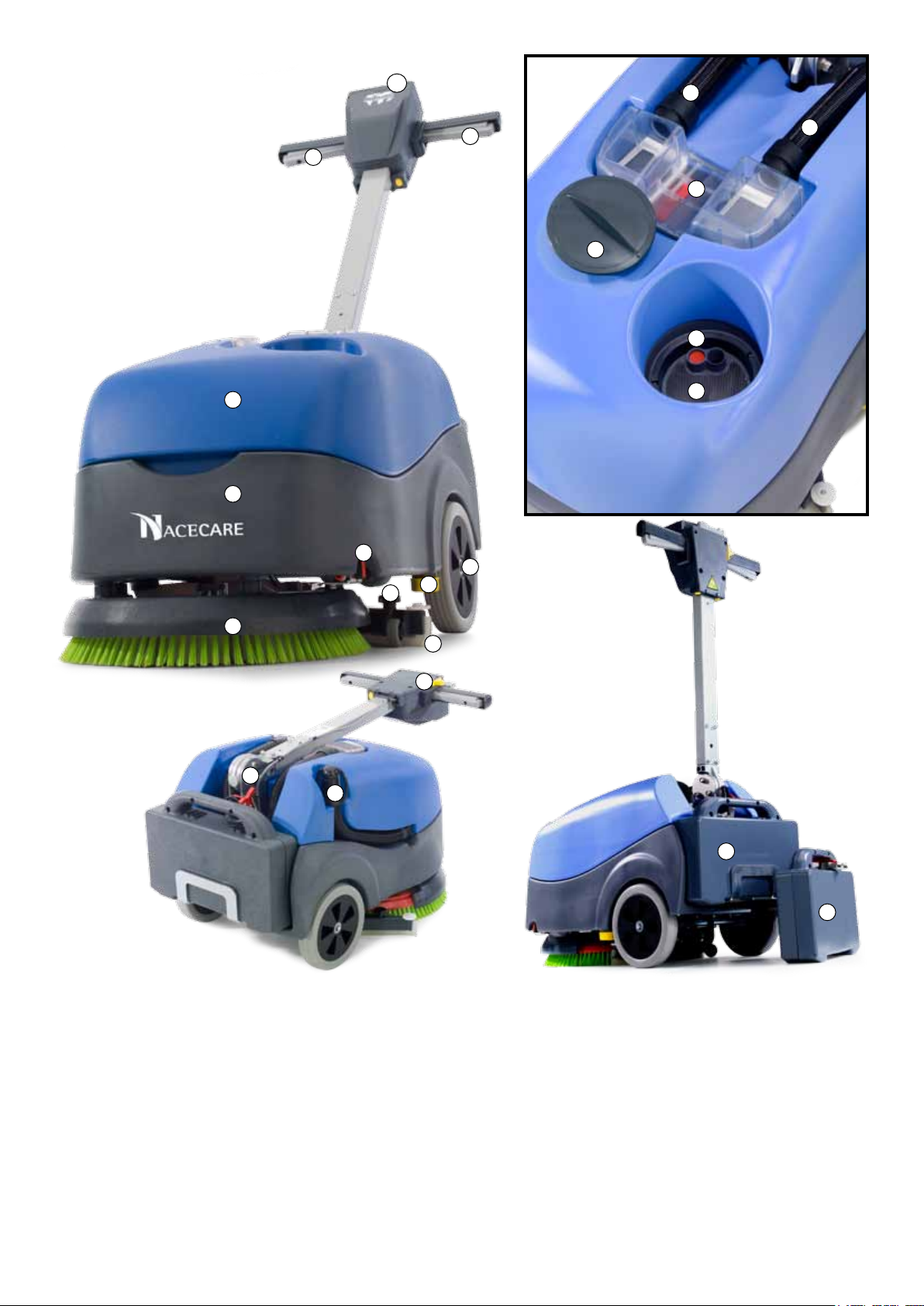
Machine Overview
1
12
2
2
13
14
15
3
4
8
7
10
9
16
11
5
18
19
1. Operator control panel ( see page 4 )
2. On / Off Lever
3. Waste water tank
4. Clean water tank
5. Brush deck
6. Squeegee blades
7. Floor-tool retaining knobs
8. Clean-water on / off tap
9. Clean-water emptying cap
10. Rear moving wheels
11. Floor-tool vacuum hose
6
17
20
21
12. Vacuum hose
13. Separator
14. Clean-water ller cap
15. Clean-water level indicator
16. Clean-water tank ll point
17. On / Off switch
18. Battery connector
19. Top tank (waste water) drainage hose
20. Battery
21. Spare / replacement battery
3
233969 / 01/13 (A20)
Page 4
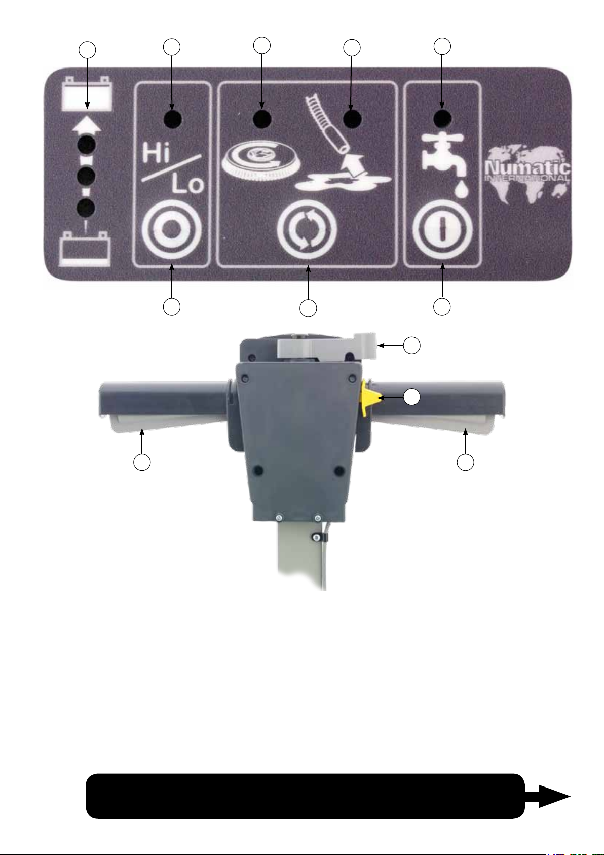
Control Panel Overview
1
2
3
4
5
11
6
7
8
9
10
11
1
2
3
4
5
6
Battery Charge Level Indicator
Hi / Lo Indicator
Brush Operation / Load Indicator
Vacuum Indicator
Water Flow Indicator
Hi / Lo Button
Instructions oncontrol panel set up and use,
7
8
9
10
11
For full easy to follow
see machine operationset-up page 14
4
Cycle sequence button
Water Flow On / Off Button
Handle Position Lever
On / Off Switch
On / Off Lever
233969 / 01/13 (A20)
Page 5
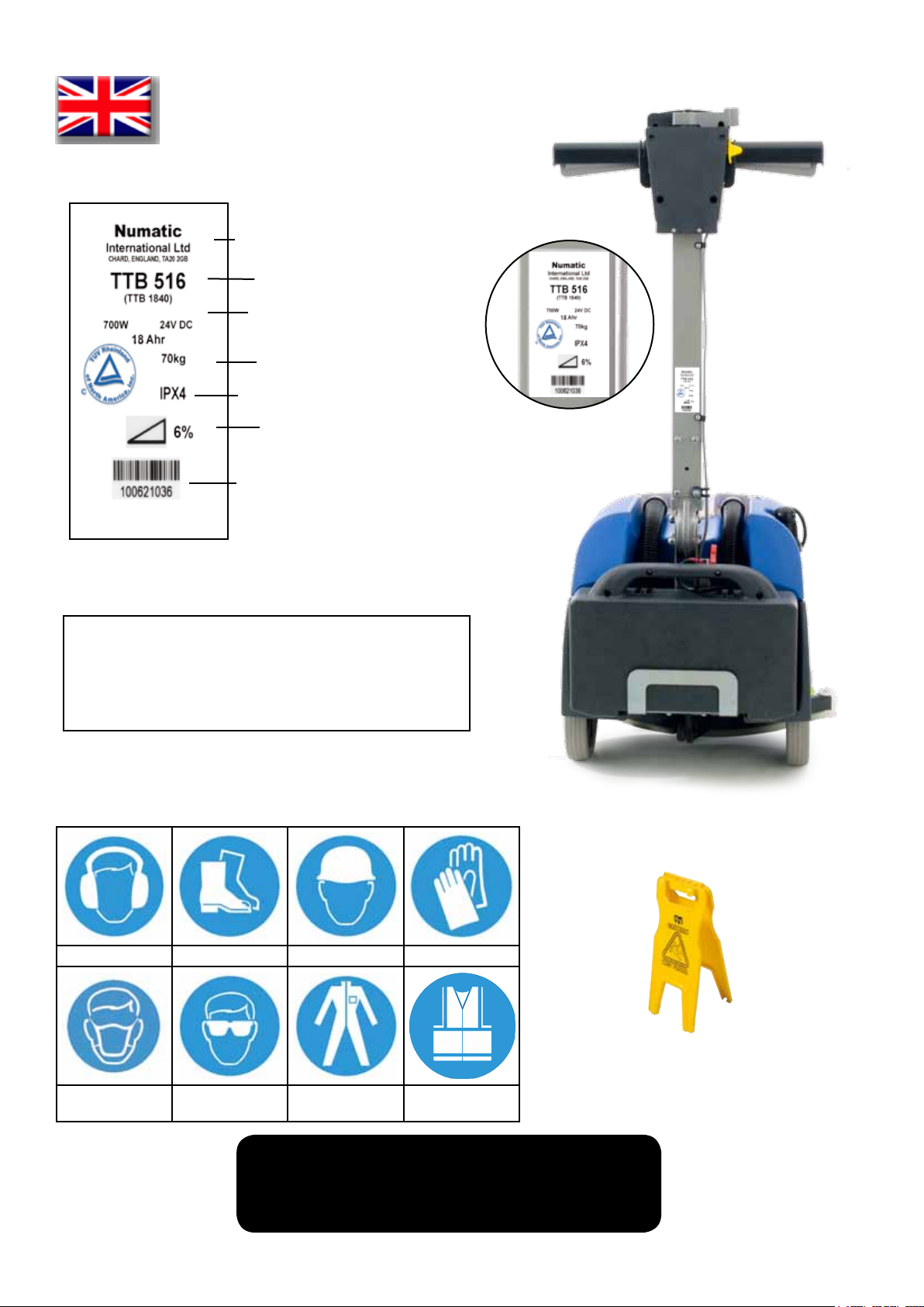
Rating Label
About the Machine
Company name and address
Machine description
Power/ Voltage/ Frequency
Weight
Splash proof rating
Max gradient
Machine year / week / serial number
Safety Critical Component
Charging Lead: 18AWG x 3 core SVT Cable (Black)
Battery Charger: 100 - 240 Volt (50-60 Hz)
PPE
(Personal protective equipment) that may be required for certain operations.
Ear Protection Safety Footwear Head Protection Safety Gloves
Caution oorsign
Dust/Allergens
Protection
Eye Protection Protective
Clothing
A risk assessment should be
conducted to determine which PPE should be worn.
Hi-Vis Jacket
Note:
5
233969 / 01/13 (A20)
Page 6

ORIGINAL INSTRUCTIONS
READ MANUAL BEFORE USE
Information for Scrubber Dryer
Component Interval Inspect for
Charging Lead DAILY scufng, cracks, splits, conductors showing
Brushes DAILY bristle damage, wear, drive collar wear
Squeegee Blade BEFORE EACH USE wear, cracks, splits
Filters BEFORE EACH USE clogging and debris retention
Tanks AFTER EACH USE rinse dirty water tank after use
CAUTION:
Read the instruction manual before using the appliance.
This product meets the requirements of CSA / CAN 60335-2-72
WARNING:
As with all electrical equipment care and attention must be exercised at all times during its use, in addition to ensuring
that routine and preventative maintenance is carried out periodically in order to ensure its safe operation.
Failure to carry out maintenance as necessary, including the replacement of parts to the correct standard could render
this equipment unsafe and the manufacturer can accept no responsibility or liability in this respect.
When ordering spare parts always quote the Model Number / Serial Number specied on the Rating Plate.
Warning do not use on slopes exceeding 6%.
This appliance is not intended for use by persons (including children) with reduced physical, sensory or mental
capabilities, or lack of experience and knowledge, unless they have been given supervision or instruction concerning
use of the appliance by a person responsible for their safety.
Children should be supervised to ensure that they do not play with the appliance.
NOTE:
This machine is also suitable for commercial use, for example in hotels, schools, hospitals, factories, shops and
ofces for other than normal housekeeping purposes.
CAUTION:
This machine is not suitable for picking-up hazardous dust.
Do not use on surfaces having a gradient exceeding that marked on the appliance.
The machine is not to be stored outdoors in wet conditions.
This machine is for indoor use only.
DO’S AND DON’TS
DO ensure only competent persons unpack/assemble the machine.
DO keep your machine clean.
DO keep your brushes in good condition.
DO replace any worn or damaged parts immediately.
DO regularly examine the power cord for damage, such as cracking or ageing. If damage is found, replace the cord
before further use.
DO only replace the power cord with the correct Numatic approved replacement parts.
DO ensure that the work area is clear of obstructions and / or people.
DO ensure that the working area is well illuminated.
DO pre-sweep the area to be cleaned.
DON’T use steam cleaners or pressure washers to clean the machine or use in the rain.
DON’T attempt machine maintenance or cleaning unless the power plug has been removed from the supply outlet.
DON’T allow any inexperienced repairs. Call the experts
DON’T strain cable or try to unplug by pulling on cable.
DON’T leave the brush pad on the machine when not in use.
DON’T allow the machine to be used by inexperienced or unauthorised operators or without appropriate training.
DON’T use the machine without the solution tanks properly positioned on the machine, as shown in the instructions.
DON’T expect the machine to provide trouble-free, reliable operation unless maintained correctly.
DON’T lift or pull the machine by any of the operating triggers - Use the main handle.
DON’T remove the handle from the machine except for service and repair.
6
233969 / 01/13 (A20)
Page 7
WARNING:
Only use brushes provided with the appliance or those specied in the instruction manual.
The use of other brushes may impair safety.
A full range of brushes and accessories are available for this product.
Only use brushes or pads which are suitable for the correct operation of the machine for the specic task being performed.
It is essential that this equipment is correctly assembled and operated in accordance with current safety regulations.
When using the equipment always ensure that all necessary precautions are taken to guarantee the safety of the
operator and any other persons who may be affected.
Wear non-slip footwear when scrubbing. Use a respiratory mask in dusty environments.
The machine, while charging, must be positioned so that the mains plug is easily accessible.
When cleaning, servicing or maintaining the machine, replacing parts or converting to another function the power
source shall be switched off.
Mains operated machines shall be disconnected by removing the power plug, and battery operated machines shall be
disconnected by removing the isolating pin (Battery pack).
Machines left unattended shall be secured against unintentional movement.
Operators shall be adequately instructed as to the correct use of the machine.
PRECAUTIONS WHEN WORKING WITH BATTERIES
1. Always wear protective clothing e.g. face visor, gloves and overalls when working with batteries
2. Whenever possible always use a properly designated and well-ventilated area for charging. Do not smoke or bring
naked ames into the charging area.
3. Remove any metallic items from hands, wrists and neck i.e. rings, chains etc. before working on a battery.
4. Never rest tools or metallic objects on top of the battery.
5. When charging is complete disconnect from the mains supply.
6. The batteries must be removed from the machine before it is scrapped.
7. The machine must be disconnected from the supply when removing the battery.
8. The batteries are to be disposed of safely and in accordance with the battery directive.
9. Only use genuine NUMATIC replacement batteries.
10. Do not allow the batteries to become fully discharged; it may not be possible to recharge them. Batteries should
not be discharged below 9.5 volts with 10 amps owing.
11.Do not allow one battery to be discharged separately to the other.
12.Do not mix batteries from different machines.
13. The batteries tted to this product are Valve Regulated Lead Acid (VRLA) gel electrolyte type. The tting of any
other type of battery may cause a safety hazard.
BATTERY CARE
1. Always recharge the batteries after use. This can be done at any time its not necessary to wait until they are fully
discharged; they do not develop a “memory”.
2. Leaving the charger to operate for a minimum of 4 hours after the green light has come on, at least weekly, will
prolong battery life.
3. Do not store the machine with the batteries discharged.
7
233969 / 01/13 (A20)
Page 8
1
Fig 1
2
!
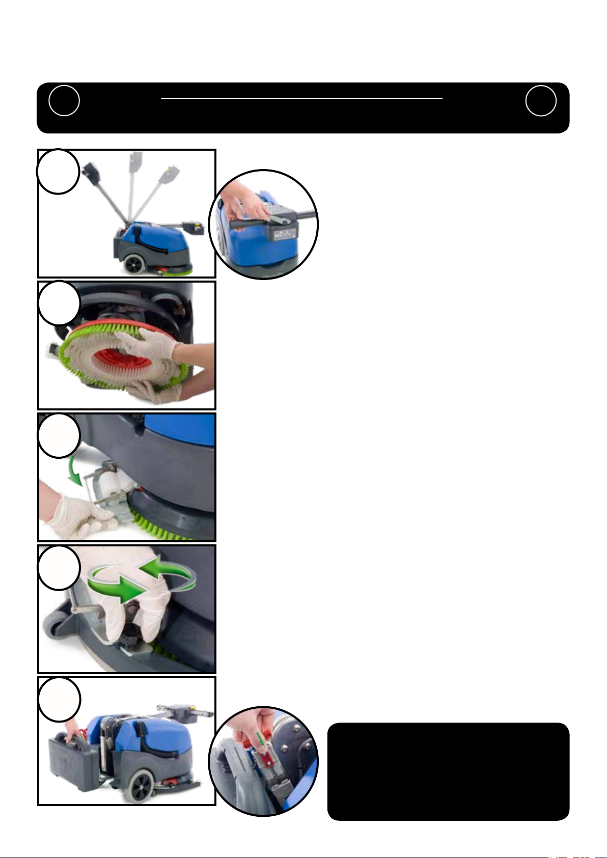
Quick Set-Up Guide
PLEASE READ BEFORE COMMENCING ANY OPERATION.
After the removal of all the packaging, carefully open and check the contents.
Ensure the Batteries are charged before use.
Using the handle position lever, move the handle into the
upright position. (Fig 1).
Fit the Brush / Pad (Fig 2).
!
3
4
5
Fig 2
Swing the oor-tool carrier from behind the brush. (Fig 3).
Fig 3
Using the two locking knobs tted to the oor-tool, secure to
the oor-tool to the oor-tool carrier. (Fig 4).
Fig 4
Fit the battery to the machine (Fig 5) and plug in the power
supply. (Fig 5a). Ensure the battery has been charged before
use.
Fig 5
Fig 5a
Fill the clean-water to a Max of 18 litres
(see page 10)
For operation and cleaning
controls (see page 14)
8
233969 / 01/13 (A20)
Page 9

Machine Set-Up
ALWAYS ENSURE THAT THE BATTERY IS DISCONNECTED
!
Fitting the brushes
Featuring the Nulock brush system.
The brush is simply pushed and twisted to lock, making tting and removal a simple process.
Only use manufacturer supplied brushes.
This machine requires a 16 inch brush or a 16 inch pad.
BEFORE MAKING ANY ADJUSTMENTS
Slide the brush / pad under the brush deck (Fig 6).
Fig 6
!
Fit the brush / pad onto the Nulock drive chuck, twist to lock
the brush / pad in place (Fig 7).
Fig 7
Safety gloves are recommended for the changing of used brushes.
Fitting the Floor Tool
The oor tool has been designed for quick tting, allowing easy squeegee blade replacement and a safety knock-off
feature if the oor tool gets snagged, whilst in transit.
Swing the oor-tool carrier to the side of the machine
(Fig 8).
Fig 8
Note:
It is easier to t the oor-tool if the weight of the machine is
resting on the brush. Ensure the brush is tted rst.
Fig 9
Secure to the carrier using the
two knobs tted to the oor-tool
carrier (Fig 9) - (Fig 9a).
Do not over tighten the retaining
knobs.
9
Fig 9a
233969 / 01/13 (A20)
Page 10

Machine Set-Up
Filling the clean-water tank
The TTB 516 is equipped with a large 5 US Gallons clean-water tank allowing large areas to be cleaning in a
single ll.
To ll the clean-water tank, remove the ller cap (Fig 10).
Fig 10
Fill using either a hose, bucket or a suitable container. (Fig 11).
Fig 11
Note.
Great care must be taken to ensure that contaminants (leaves,hair, dirt, etc) are not allowed to enter the
clean-water during the lling process.
If using a bucket or similar, ensure it is always clean and free from debris.
Fill Level Indicator
Fill the clean water tank to a maximum of 5 US Gallons, including cleaning chemicals if required.
Follow chemical manufacturing guide lines.
This allows the machine to be tipped back and moved without spillage (see page 12).
Use the ll indicator
(Fig 12).
Fig 12
Fig 13
Showing the clean-water tank empty
(Fig 13).
10
Fig 13a
Showing the clean-water tank full
(Fig 13a).
233969 / 01/13 (A20)
Page 11

Machine Set-Up
WHEN HANDLING AND MIXING CHEMICALS.
! !
Control of Substances Hazardous to Health (COSHH)
For best results use a non-foaming type of chemical, dilute to the manufacturers specication.
For further guidance on hazardous substances refer to health and safety instructions online.
Visit http://www.hse.gov.uk/ for UK information.
Water Flow Adjustment
Always ensure that chemical manufacturers safety guidelines are followed.
Only use chemicals recommended for use in auto scrubber-driers.
Located on the left of the machine is the On / Off water tap
(Fig 14).
Ideally set the tap to 450 this enables the cleaning
solution to last the same time as a fully-charged battery
(Fig 15).
0
Fig 14
Important
Do not operate machine unless the Operator Manual has been read and fully understood.
!
45
Fig 15
Pre-cleaning advice.
Before performing the cleaning operation, place out
appropriate warning signs and sweep or dust-mop the oor
(Fig 16).
!
Numatic part (629044) Wet Floor sign
(available if required)
11
Fig 16
233969 / 01/13 (A20)
Page 12

Machine Set-Up
Moving the machine
Caution
! !
When moving or lifting the TTB 516, follow the national safety guidelines on lifting.
When the bottom tank (clean water) is full the machine can be
tilted to a maximum of 450 (Fig 17).
Fig 17
When the top tank (waste water) is full the machine can be
0
tilted to a maximum of 10
(Fig 18).
for transporting to dumping area
Fig 18
Fig 19
Transport the machine by tilting back on to the main transit
wheels (Fig 19).
Weight of empty machine (g 20).
Without the battery pack:- 38.5Kg (85 lbs).
Battery pack weight:- 13.5Kg (30 lbs).
Complete machine :- 52Kg (115 lbs)
Fig 20
Caution
! !
Ensure both tanks are empty and the battery has been removed before attempting
to lift the machine.
12
233969 / 01/13 (A20)
Page 13

Machine Operation
Pre-scrub mode
The TTB -516 has been designed to cope with a variety of oor types and different levels of soiling.
On heavily soiled oors use a ‘double scrub’ technique.
First pre-scrub the oor with the oor-tool in the raised position (Fig 21), allow the chemical time to work, then scrub
the area a second time with the oor-tool lowered.
Fig 21 Fig 22 Fig 23
To raise the oor-tool, ensure the oor-tool carrier is central to the machine (Fig 22).
Lift the lever near the base of the handle and lock into position (Fig 23).
Note The lever moves upward and backward motion to lock the oortool in the raised position.
Floor tool in use
The clean-water / chemical mix is dispersed via ‘THRU-FEED’
system.
The waste water is then retrieved by the oor-tool
(see page 9).
Overlap the scrubbing path by 10cm to ensure an even clean
(Fig 24).
Fig 24
If streaking occurs, wipe the oor-tool blades clean (Fig 25).
Note Care must be taken to reduce speed when cornering or when manoeuvring around obstacles.
Fig 25
Hi - Lo Setting
13
233969 / 01/13 (A20)
Page 14

Setting the cleaning controls
1 1
Fig 26
45
0
Fig 27
To activate the control panel: press the cycle button or press a trigger (Fig 26).
To start: hold down either trigger and press the yellow start
button once (Fig 26).
Whilst the brush motor is running press the tap On / OFF
button for uid control (Fig 27a), the clean tank tap must be
open.
Ideally set the tap to 450 (Fig 27) this enables the cleaning
(Fig 27a)
(Fig 27b)
solution to last the same time as a fully-charged battery .
When the triggers are released the brush motor and the
cleaning solution pump will switch off, the vacuum motor will
continue for 10 seconds.
Press the cycle button to operate the brush only
(Fig 27b).
The start sequence is required in this mode.
The tap button will operate in this mode.
(Fig 27c)
(Fig 27d)
Press the cycle button again to get vacuum only.
The start button and triggers are not required in this mode.
(Fig 27c).
Press the cycle button to switch this mode off and return to
default mode.
The panel if unused will automatically turn off after 60
seconds.
Brush overload.
The brush LED light will ash if the brush motor has been
overloaded (Fig 27d).
Releasing the handle triggers will allow the machine to stop
and reset.
If the brush motor keeps overloading
consider using a different type of brush.
Heavy brush load decreases the available battery run
time.
14
233969 / 01/13 (A20)
Page 15

Regular Maintenance
ALWAYS ENSURE THAT THE BATTERY IS DISCONNECTED
! !
The TTB 516 has been designed with ease of use in mind, this included easy stripping-down and cleaning.
A
Fig 28
PRIOR TO ANY MAINTENANCE OPERATION
After use, empty waste-water tank using
emptying hose and ush-out with clean
Fig 29
water.
Remove the two hoses to disconnect the separator from the
machine (Fig 28).
Lift off the separator. The separator has a sealing-rubber
which should be examined at every clean-down (Fig 29).
Rinse using clean water.
A
Fig 30 Fig 31
Remove the two lters clipped into the separator and ush with clean water (Fig 30)(Fig 30a).
Replace by tting the rear of the lter rst then clipping the front to lock in place (Fig 31) (Fig 32).
Fig 33
Fig 30a
Disconnect and remove the
battery before proceeding with
tank removal (Fig 33).
Once emptied the top
waste-water tank can simply be
lifted off. (Fig 33a).
Fig 33a
The clean-water tank can be drained via the yellow cap tted
to the left hand side of the machine. The cap has a rubber
seal and might require a spanner to remove. (Fig 34).
NOTE:
Avoid over tightening the clean water draining cap.
Fig 32
Fig 34
15
233969 / 01/13 (A20)
Page 16

Regular Maintenance
Removing the Clean Water Tank
Fig 35 Fig 36
Replacing the Clean Water Tank
Once the clean-water tank has been emptied, the tank can be
removed.
Firstly detach the water feed pipe from the tap, this can be
done by pushing the red tap clip in whilst pulling off the pipe.
(Fig 35).
Fig 36a
Fit the suction hose to the oor tool (Fig 37) and pass through
the hole in the clean water tank (Fig 37a).
Place the tank onto the machine base.
The black suction hose from the
oor-tool simply pulls off the oor tool
(Fig 36).
Inside the clean water tank is a lter,
located below the clean water inlet
(Fig 36a)
Clean all hoses and lters by ushing
with clean water.
Fig 37
Fig 37a
Fig 38
Replacing the Waste Water Tank
NOTE:
Ensure the water feed pipe locates in the channel
moulded into the base of the tank (Fig 38).
The water feed pipe simply
pushes onto the tap. (Fig 38a).
Fig 38a
Place the suction hose as shown
(Fig 39).
Place the tank onto the machine
(Fig 39a).
Fig 39
Fig 40
Fig 39a
Ret the separator and reconnect the vacuum and suction
hose (Fig 40).
16
233969 / 01/13 (A20)
Page 17

Changing the Floor-Tool Blades
ALWAYS ENSURE THAT THE BATTERY IS DISCONNECTED PRIOR TO ANY
! !
Fig 41
MAINTENANCE
To change the oor-tool, rstly swing the oor-tool clear of the
machine (Fig 41).
Undo the two oor-tool retaining knobs (Fig 42).
Fig 42
Fig 43 Fig 44 Fig 45
Unscrew the four knobs securing the blade holder (Fig 43).
Remove the blade holder (Fig 44).
Replace the Squeegee blades using (606261) replacement blade set (Fig 45), tting the blades on to the moulded
location lugs.
Retting the Floor Tool Blades
Ret the blade holder, retain using the two outer knobs
1. Floor-tool main body
2. Blade carrier
Fig 46
(Fig 46)
Fig 47
1
Ensure the slotted blade goes to the front of the
oor-tool (Fig 47).
Note:
The blades are designed to be reversible, thus
extending their useful working life.
Ret the oor-tool using the two central knobs to
the oor-tool.
Refer to Page 9 for tting instructions.
3. Rear blade
4. Front blade (slotted)
5. Retaining Knobs x 4
Use Genuine NUMATIC spare parts.
use
Replacement Blade Set (606261)
2
3
4
17
5
233969 / 01/13 (A20)
Page 18

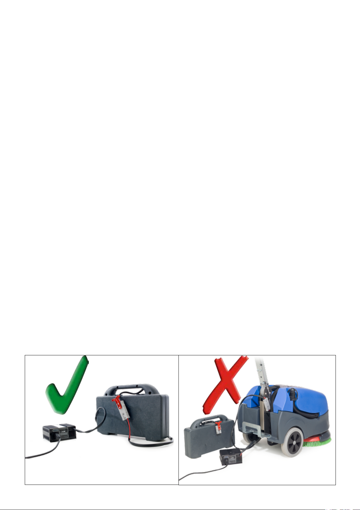
Removing the battery
Battery Care
Unplug the battery from the machine using the red
connection handle (Fig 48).
The battery can then be lifted from the machine for
storage or charging (Fig 49).
Fig 48
Removing the battery pack fuse
Fig 51
Fig 52
Fig 49
Fig 50
The battery pack comes with a 40 amp safety
fuse tted (Fig 50).
Remove the six screws holding the battery pack
together (Fig 51).
Split the pack and replace the fuse using
(208526) Numatic approved part (Fig 52).
Recharge the machine fully after its last use.
Do not leave the machine in a discharged state.
Under abnormal use;
i.e. leaving the machine without charging for a period of time, we advise that you disconnect the battery from
the machine.
If the machine will be standing unused for a period of 30 days or more, then batteries must be fully charged
Note.
Batteries should be recharged every three months.
Charge fully the day before you start using the machine again.
18
233969 / 01/13 (A20)
Page 19

To ensure your machine remains at its maximum efciency and prolong your battery life, please follow
Machine Charging
the simple steps below:
Fig 53
Under normal daily usage:
Recharge batteries after each use
regardless of machine operation
time (g 53).
Connect the charger unit to the
battery and plug the charger into a
suitable power supply (Fig 53a).
The battery charge state is shown by the light sequence
on the front of the charger (g 54).
Signal (LED) Meaning
Red LED on First phase of charge in progress
Yellow LED on Second phase of charge in progress
Green LED on
Red LED ashing
Fig 54
Yellow LED ashing Battery not connected
Green LED with 2 ashes
Red LED with 2 ashes
The battery meter displays the charge level of the batteries; when fully charged,
all meter lights are illuminated (Fig 54).
As the machine is used and the batteries are discharged, the meter lights will go out from
top to bottom.
If the battery-charge level is allowed to discharge to the point that only one red light remains
illuminated, the operator should either replace or charge the battery.
The battery supplied for this machine allows for a run time of 45 mins approx (Lo Mode),
when fully charged.
The battery pack must be fully discharged and recharged over a few cycles and brushes
need to be worn in to achieve maximum efciency.
Fig 53a
End of charge or maintenance phase
Disconnect from power supply
Switch power supply, OFF then ON, to restart the
charging cycle
Unsuitable battery or charging malfunction
Safety timer exceeded
Internal short circuit
Disconnect from power supply
Switch power supply, OFF then ON, to restart the
charging cycle
INITIAL TEST
Battery charger congured for recharging Gel or
AGM batteries
Battery charger congured for recharging
Lead-acid (Wet) traction batteries
Charge time is approximately 6 hours.
Spare replacement batteries are available from your supplier.
See TTB-516 Spares list for part numbers.
The TTB-516 come with its own stand-alone charger.
Insert the charging lead required for your country into the charger.
Connect the charger to a suitable power supply.
Once mains power is connected the red charging indicator will illuminate.
To ensure a full charge, the battery should be left for a period of 6 hrs.
Once fully charged, disconnect the charging lead from both the power supply and the machine.
19
233969 / 01/13 (A20)
Page 20

Trouble-Shooting
PROBLEM CAUSE SOLUTION
Machine will not operate Missing or blown fuses
Battery not connected
Low battery charge
Vacuum will not operate Vacuum not turned on Turn on vacuum (page 17)
Poor water pick-up Waste-water tank full
Clogged / blocked vacuum hose
Loose hose connections
Debris basket lter clogged/blocked
Separator lter clogged / blocked
Poor separator seal
Damaged separator seal
Damaged / split vacuum hose
Damaged oor-tool blades
Low battery charge
No brush / scrub function No brushes tted
Brush overloaded
Little or no water ow Clean-water tank empty
Clean-water tank lter blocked/ clogged
Incorrect water ow setting
Machine just ‘stops’ while
To much load on the brush system
operating
Blown fuse in Battery pack
Fit or replace fuse (page 8)
Connect battery (page 8)
Charge batteries (page 19/21)
Empty waste-water tank (page 17)
Remove and clean (page 17)
Push tight connections (page 17)
Remove and clean (page 17)
Remove and clean (page 17)
Clean and ret (page 17)
Renew (contact service dept)
Renew (contact service dept)
Renew (contact service dept)
Recharge batteries (page 19 /21)
Check and t (page 10)
Reset machine (page 14 g 27d)
Fill clean-water tank (page 11)
Remove and clean (page 17)
Adjust tap as desired (page 14)
Reset the machine and decrease the
brush load to best suit the oor type
(page 14. g 27d)
Replace 40 Amp fuse (page 18)
Specications
Brush Motor Vac Motor
400W 24V 300W 16” 16” 52 Kg IPX4
Area
Performance
per battery
pack
1050m
2
Fluid Flow
(Tap at 45’)
0.09 gpm
(60 mins)
Brush
Sizes
Brush / Pad
Pressure
27.4/
26.2 g/cm2
Pad
sizes
Speed
Hi-150 rpm
Lo-130rpm
Weight
Recharge
time
6 hrs 0-4.2Kph 0.6 m/s
Protection
Class
Cleaning
Speed
Run Time
per battery pack
Hi - 35 mins
Lo - 45 mins
Hand Arm
Vibration
Hi-70.3 dB(A)
2
Lo-68.2 dB(A)
Model TTB-516
Power
2 x 12V (24V) 18Ahr
Noise Size
850mmx
1132mmx
520mm
20
233969 / 01/13 (A20)
Page 21

Recommended Spare Parts - TTB-516
16”
Scrubbing Brush
606105
606260 TTB-516 BATTERY PACK (BOXED) 606261 TTB-516 REPLACEMENT BLADE SET
606266 TTB-516 BATTERY & CHARGER PACK (UK) 303985 TTB-516 FILLER CAP
606267 TTB-516 BATTERY & CHARGER PACK (EURO) 237268 FILLER CAP LID
606268 TTB-516 BATTERY & CHARGER PACK (SWISS) 237232 TTB-516 SEPERATOR FILTER
606269 TTB-516 BATTERY & CHARGER PACK (CSA) 237260 TTB-516 GRIT BASKET
606270 TTB-516 BATTERY & CHARGER PACK
(SOUTH AFRICA)
606271 TTB-516 BATTERY & CHARGER PACK (AUS) 213055 TTB-516 VAC HOSE
606272 TTB-516 CHARGER PACK (UK) 208471 CONSTANT TENSION CLIP
606273 TTB-516 CHARGER PACK (EURO) 303997 TTB-516 DUMP-HOSE
606274 TTB-516 CHARGER PACK (SWISS) 208448 TANK DRAIN CAP
606275 TTB-516 CHARGER PACK (CSA) 208526 REPLACEMENT 40AMP FUSE
606276 TTB-516 CHARGER PACK (SOUTH AFRICA) 208455 M5 KNOB (BLACK)
606277 TTB-516 CHARGER PACK (AUS) 208537 CONSTANT TENSION CLIP (VAC HOSE)
(MDA-21)
606400
ASSEMBLY
231054 TTB-516 SUCTION HOSE
ASSEMBLY
16”
Drive Board
Padloc
NOTES
..........................................................................
..........................................................................
...........................................................................
...........................................................................
...........................................................................
...........................................................................
...........................................................................
...........................................................................
...........................................................................
...........................................................................
...........................................................................
...........................................................................
...........................................................................
21
233969 / 01/13 (A20)
Page 22

TTB-516
DRW-7279 (A06) 06:08:2012
22
233969 / 01/13 (A20)
Page 23

NOTES
..........................................................................
..........................................................................
...........................................................................
...........................................................................
...........................................................................
...........................................................................
...........................................................................
...........................................................................
...........................................................................
...........................................................................
...........................................................................
...........................................................................
...........................................................................
...........................................................................
...........................................................................
...........................................................................
...........................................................................
...........................................................................
...........................................................................
...........................................................................
...........................................................................
...........................................................................
...........................................................................
...........................................................................
...........................................................................
23
233969 / 01/13 (A20)
Page 24

This machine has been packed
with the following
Charging Lead + Charger
Brush / Pad
Battery Pack
Floor Tool
Signed
233969 / 01/13 (A20)
 Loading...