

Page 1

OWNERS MANUAL
ST900 SERIES
1205 Britannia Road East, Mississauga, ON L4W 1C7
Phone: 1-800-387-3210 Fax: 1-800-709-2896
Page 2

ON CONSIGNMENT OF THE MACHINE
When the machine is consigned to the customer, an immediate check must be performed tonsure all the material mentioned in
the shipping documents have been received and moreover to find out that the machine hasn’t suffered damage during
transportation. If damage has occurred, get the shipping agent to verify immediately the amount and nature of the damage
suffered and at the same time informs our claim department. It is only by prompt action of this type that compensation for
damage may be successfully claimed.
INTRODUCTION
This is a floor-cleaning machine, which, using the mechanic abrasive action of two rotary brushes and the chemical action of
a water-detergent solution, is able to clean any type of floor. During its advance movement, it picks up the removed dirt and
the detergent solution, which has not been absorbed by the floor. The machine must be used only for such purpose. We would
impress upon you that any machine will function efficiently and operate successfully, only if used correctly and maintained in
fully efficient working order. We therefore suggest you to read this instruction booklet carefully and re-read it whenever
difficulties arise in the course of machine use. Our Service Department is at your disposal for all such advice and servicing as
may prove necessary.
NOTE:M65=ST965
M70=ST980
M75=ST985
M83=ST995
- 1 -
Page 3

Symbol denoting up - down of the brushes base. It is used to indicate
the switch to raise or lower the brushes base.
Symbol denoting charge level of the batteries.
Symbol denoting up - down of the squeegee. It is used to indicate the
switch to raise or lower the squeegee.
Symbol denoting regulation cock.
Symbol denoting the horn button.
Symbol denoting the MAIN POWER on/off switch.
Symbol denoting the forward/reverse switch. According to its position
the machine moves forward or backward.
Symbol denoting maximum temperature of the cleaning solution to be
used.
Symbol denoting the drain hose of the recovery tank.
- 2 -
Page 4

HOW TO HANDLE THE PACKED MACHINE
Figure 1
The machine is packed in a specific packageprovided on a pallet so
that it can be moved with a forklift. The packages cannot be placed
top of each other.
Total weight:
- Magna 65- 420 kg
- Magna 75-83: 440 kg-
- Magna 70S: 420 kg
- The overall dimensions are:
- Magna 65/75/70S/83A
- 1600 mm B : 930 mm C : 1780 mm
HOW TO UNPACK THE MACHINE
Figure 2
1. Remove the outer package.
2. The machine is fixed on the pallet with wooden wedges, which
block the wheels.
3. Remove these wedges.
Figure 3
4. Using a chute, get the machine down from the pallet, pushing it
in reverse motion. Avoid violent blows to the baseunit
5. Keep the pallet for future transport necessities.
INSTALLATION OF THE BATTERIES INTO THE MACHINE
Figure 4
The batteries are fitted in the appropriate compartment under the seat
and under the recovery tank and must be handled by using
appropriate lifting equipment suitable both for the weight and for the
coupler system. They must moreover satisfy the requirements quoted
in the Specification CEI 21-5. For maintenance and daily recharge of
the batteries, it is necessary to follow strictly all the instructions given
by the manufacturer or from his dealer. Specialized staff must carry
out all the installation and maintenance operations.
- 3 -
Page 5
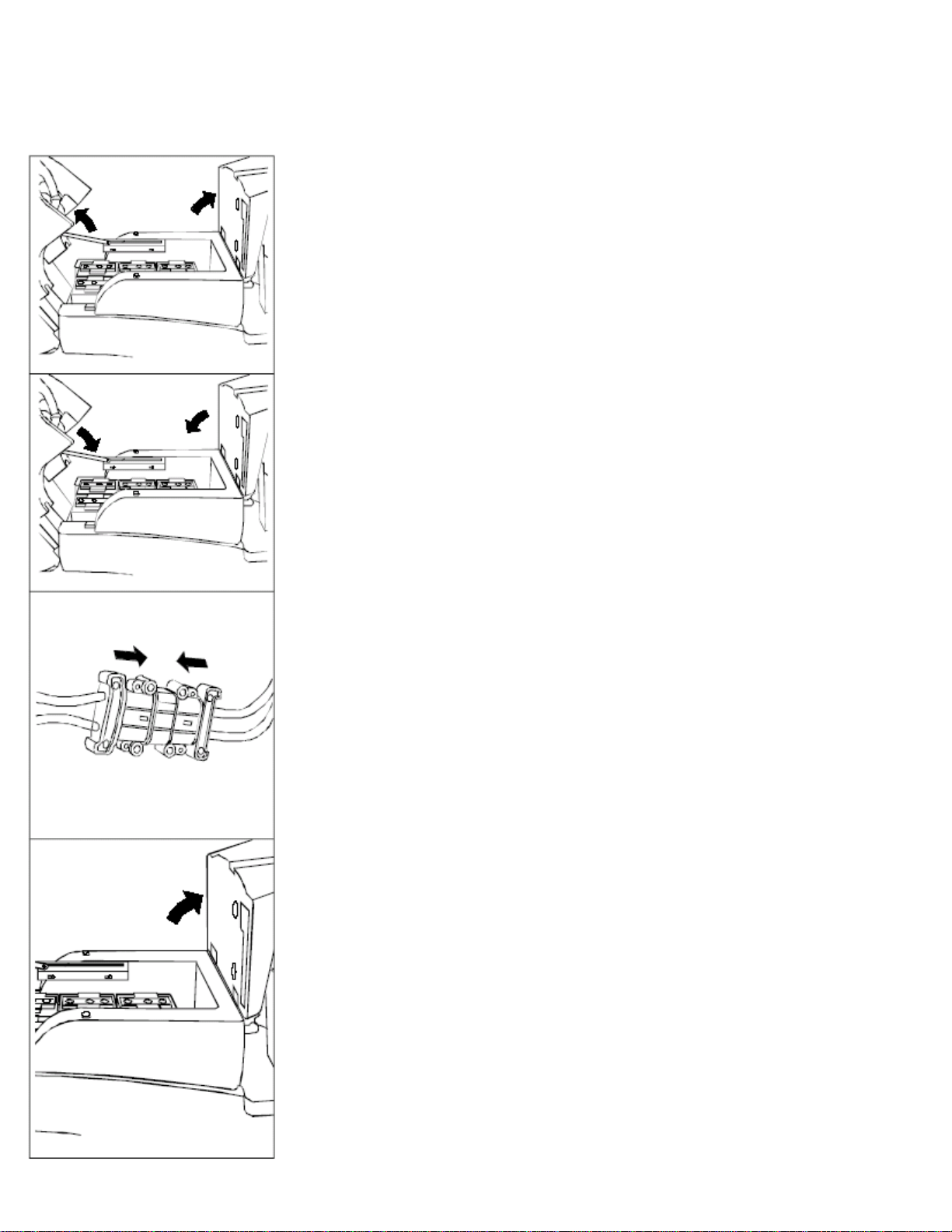
Figure 5
For battery installation:
1. Lift the base support of the seat.
2. Lean the seat on to the steering wheel
3. Rotate back the recovery tank towards the rear until it locks in
place.
4. Put the batteries into position and connect the battery cables.
Figure 6
5. Unfasten the support and put the recovery tank into its working
position
6. Lower the base support of the seat.
CONNECTION OF THE BATTERY CHARGER
Figure 7
1. Raise the seat base support.
2. Disconnect the machine connector from the battery connector.
3. Connect the battery charger directly to the battery connector.
The coupling connector of the battery charger is delivered in the
bag where this instruction booklet is found and must be
assembled on the battery charger cables following the suitable
instructions (see instruction booklet of the battery charger).
ATTENTION: this operation must be carried out by specialized staff.
A wrong or defective connection of the cables to the connector may
cause serious damages to people or things.
RECHARGE OF THE BATTERIES
Figure 8
Make sure that the battery charger fits the installed batteries either for
capacity or for type (lead/acid or GEL and equivalents).
ATTENTION: never charge a GEL battery with an unsuitable battery
charger. Carefully follow the instructions given by the manufacturer
of batteries and battery charger. To prevent permanent damage to the
batteries, avoid their complete discharge and effect recharging within
a few minutes after that the signal lamp of discharged batteries begins
to blink.
NOTE: Never leave the batteries completely discharged, even if the
machine is not being used. When recharging the batteries, keep the
base support of the seat lifted. After every 20 recharging operations,
- 4 -
Page 6
check the level of the electrolyte and, if necessary, top off with
distilled water.
LEVEL INDICATOR FOR THE CHARGE OF
THEBATTERIES
Figure 9
The batteries’ indicator is digital with 4 fixed positions and a blinking
one. The numbers which appear on the display show the approximate
charge level.4 = maximum charge, 3 = charge 3/4,2 = charge 2/4, 1
= charge 1/4,0 = (blinking) discharged batteries .
ATTENTION: A few seconds after the meter reads “0” it will start
blinking; the brush motor will then automatically switch off. Anyway,
the machine can finish to dry before recharging the batteries.
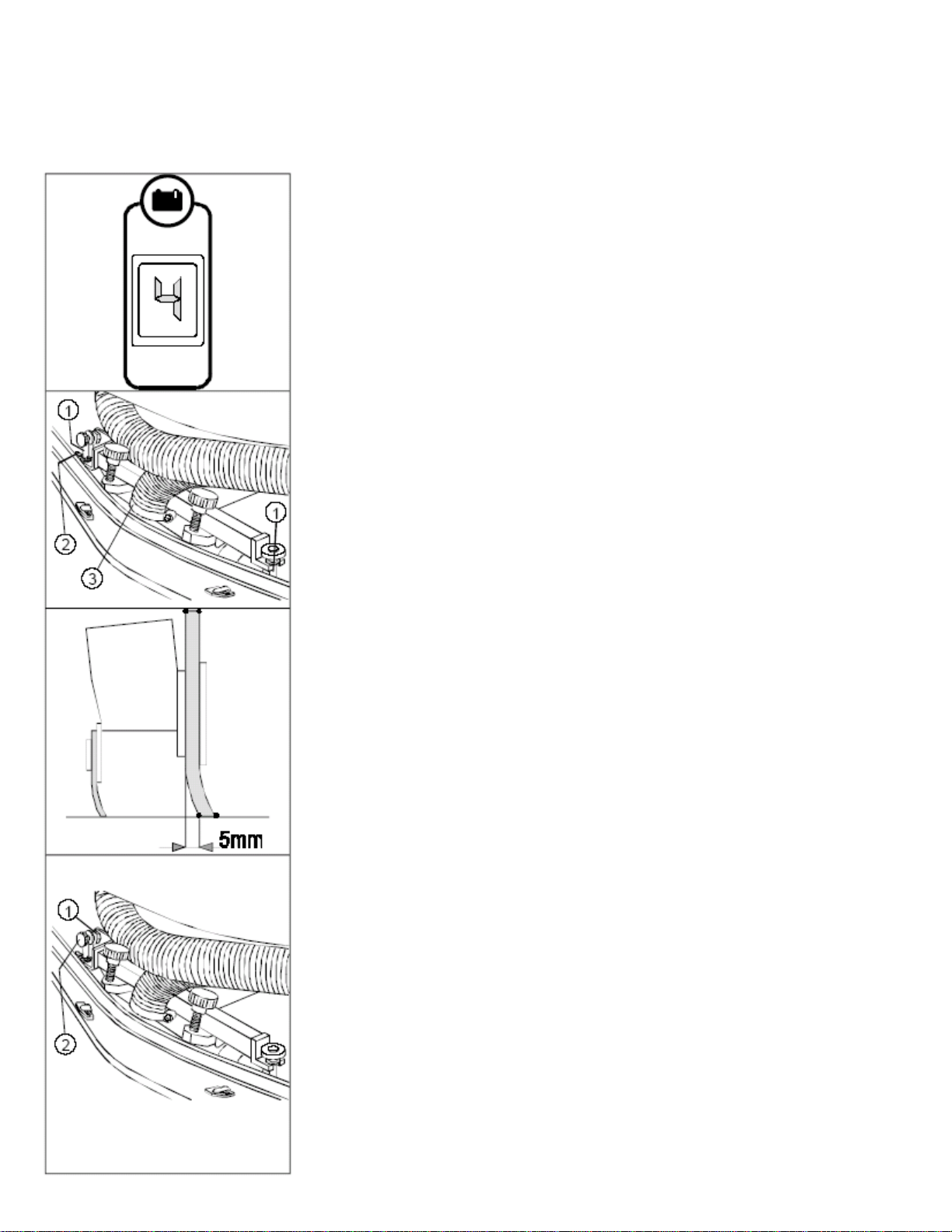
SQUEEGEE
Figure 10
The squeegee, which is packed separately from the machine, should
be installed onto the machine as shown in the figure. Insert the stud
bolts on the squeegee (1) into the proper slotted hole in the support
frame. Install the hair pin (2) into the stud bolthole. Fit the suction
hose (3) into its coupling and fix it with the appropriate clamp.
Figure 11
During operation, the rear rubber has to work slightly tilted
backwards and this equally in its whole length for about 5 mm. This
allows using the squeegee four times before it has to be replaced.
Figure 12
If it is necessary to increase the rubber bending in the central part, tilt
the squeegee body backwards, loosen the adjuster nut (1) and rotate
the knob (2) counter-clockwise. If the rubber bending is to be
noticeable at the sides of the squeegee, loosen the adjuster nut (1) and
rotate the knob (2) clockwise. After regulations have been done fix
the adjuster nut.
- 5 -
Page 7

ADJUSTMENT HEIGHT SQUEEGEE SUPPORT
Figure 13
The squeegee has to be regulated in height depending on the wearing
of the rubbers. To adjust this it is necessary to act on the knobs
(1):
- By rotating clockwise the squeegee raises;
- By rotating counter-clockwise the squeegee lowers. It is
important that the right and left little wheels are set at the same
height, only in this way the squeegee can work parallel to the
floor.
ASSEMBLY OF WASHING OR WASHING/SCRUBBINGUNIT
Figure 14
The machine is supplied as a base unit. Their are two different
washing units available, to be chosen according to the type of floor
and its conditions:
1. Washing unit with brushes. Suitable for all types of floor, and
used for routine maintenance scrubbing. Also can be used for
aggressive scrubbing, cleaning, and stripping by increasing
pressure.
2. Washing & sweeping unit with cylindrical brooms. Suitable for
rough, uneven, and grouted surfaces. Will scrub and sweep
debris in one pass and collect the solid debris into a hopper
without obstructing the squeegee rubbers.
WASHING UNIT ASSEMBLY (brushes)
Figure 15
1. Loosen the knobs (1) from the horizontal pins on the left side of
the units and rotate them outwards.
2. Position the base under the machine into the proper controls (2)
3. Rotate the knobs toward the inner part of the base and stop
them.
4. Connect the quick water coupling (3).
ADJUSTMENT HEIGHT SPLASH GUARDSRUBBERS OF
THE WASHING UNIT
Figure 16
During working operation the base splashguards rubbers must skim
over the floor.
1. To vary the height of the support, and therefore of the
splashguards rubbers, the horizontal knobs (1) must be screwed
or unscrewed.
2. After regulating correctly the rubber height, stop the knobs.
- 6 -
Page 8
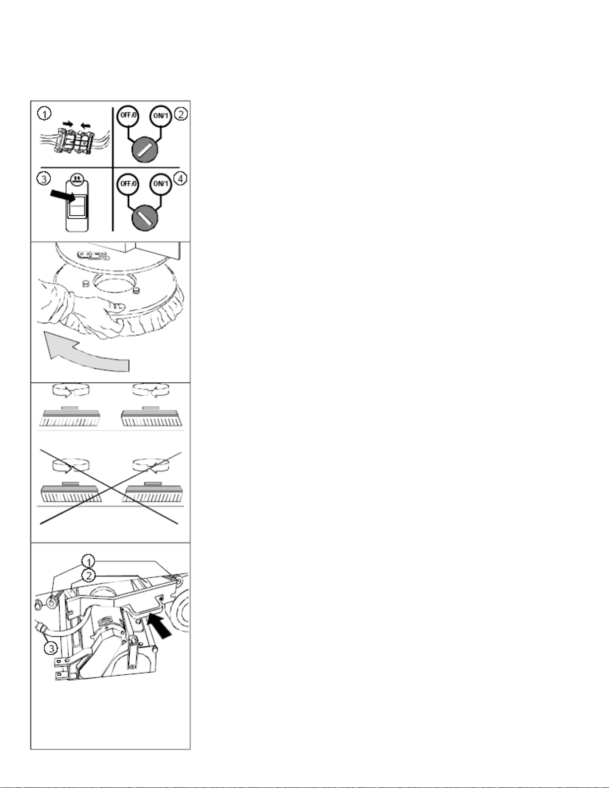
BRUSHES ASSEMBLY
Figure 17
1. Connect the battery connector.
2. Turn the key switch to the ON position.
3. With the switch raise the base.
4. Turn the key switch to the OFF position and remove key from
the instrument panel.
ATTENTION: To carry out the brush assembly operation with the
current connected could cause serious damage to machine and
persons.
Figure 18
5. With the brush base in UP position, insert the brushes into the
seat of the plate under the base until the three buttons fit into the
holes of the plate. Turn the brush so that the buttons are pushed
towards their retaining springs until the brush is clamped in
place. The figure shows the direction of rotation for the
coupling of the right brush. The left brush has to be rotated
inversely.
ATTENTION: use gloves to protect your hands when performing the
steps listed above.
Figure 19
6. It is recommended to invert daily the position of the right brush
with the left one and vice versa. If the brushes are not new and
they show deformed bristles, its better to reassemble them in the
same position (the right to the right side and the left to the left
side), to avoid that the different inclination of the bristles causes
an overload to the brushes motor and excessive vibrations.
WASHING/SCRUBBING UNIT ASSEMBLY (cylindrical brooms)
Figure 20
1. Loosen the knobs (1) from the horizontal pins on the left side of
the units and rotate outwards.
2. Position the base under the machine in the proper controls (2).
3. Rotate the knobs towards the inner part of the base and stop
them.
4. Connect the quick water coupling (3).
- 7 -
Page 9

CYLINDRICAL BROOMS ASSEMBLY
Figure 21
1. Connect the battery connector.
2. Turn the key into position ON.
3. Move the switch to raise the base.
4. Turn the key into position OFF and take it off from the
instrument board.
5. Take off the side splash guards (see ASSEMBLY AND
DISASSEMBLY ORREGULATION SIDE SPLASH GUARDS
OFTHE WASHING/SCRUBBING BASE).
ATTENTION: To carry out the brush assembly operation with the
current connected could cause serious damage to machine and
persons
Figure 22
6. With the base in UP position unfasten, by pushing downwards
and then outwards, the two movable supports (1).
7. Insert the broom into the tunnel till you block it in the holder
hub, keeping the “v” shaping as in the picture.
8. Insert the idle hub of the movable support into the brooms and
into the spring.
9. Push the support downwards, and then inwards to refasten in the
bayonet cap.
10. Regulate the brushes adjustment with the screw (2)
11. Repeat the operation also for the second support.
12. Reassemble the side splash guards (see ASSEMBLY AND
DISASSEMBLY OR REGULATIONSIDE SPLASH GUARDS
OF THEWASHING/SCRUBBING BASE).
ATTENTION: Use gloves to protect your hands when performing the
steps listed above. SIDE SPLASH GUARDS ASSEMBLY
ANDDISASSEMBLY OF WASHING/SCRUBBINGBASE
Figure 23
This operation is to be made with the base down.
1. Take off the pin (1).
2. Remove the pin (2).
3. Position the bar in the proper support.
4. Reassemble all parts following the above operations in reverse.
HOPPER
Figure 24
Check that the hopper is latched and locked.
- 8 -
Page 10

SOLUTION WATER
Figure 25
Fill the solution tank with clean water at a temperature not more than
50° C and add liquid detergent in the proper concentration following
the instructions of the manufacturer. Excess foam in the recovery tank
could damage the suction motor, so use only the minimum amount of
detergent necessary.
ATTENTION! Always use low foam detergent. To avoid the
production of foam, before starting to clean, put a minimum quantity
of antifoam liquid into the recovery tank. Never use pure acid.
RECOVERY TANK
Figure 26
Check that the inspection cover has been tightened,
Figure 27
And that the exhaust plug of the tank
Figure 28
And the plug of the exhaust pipe is closed.
- 9 -
Page 11

The rules below have to be followed carefully in order to avoid injury to the operator
and damage to the machine.
? Read the labels carefully on the machine. Do not cover
them for any reason and replace them immediately if
damaged.
? Exclusively authorized staff that has been instructed for
its use must use the machine.
? During the operation of the machine, pay attention to
other people around you, especially children.
? Do not mix different kinds of detergents. Avoid harmful
odors.
? Do not place any liquid containers on to the machine.
? The storage temperature has to be between -25°C and
+ 55° C.
? The perfect operating temperature should be between
0°C and 40°C.
? The humidity should be between 30 and 95 %.
? Do not use the machine in explosive atmosphere.
? Do not use the machine as a means of transport.
? Do not use acid solutions, which could damage the
machine.
? In order to prevent floor damage, do not leave brushes
running when machine is standing still.
? Do not vacuum inflammable liquids.
? In case of fire, use a powder extinguisher.
? Do not use water. Do not strike shelving or scaffoldings,
where there is danger of falling objects.
? Adapt the utilization speed to the adhesion conditions.
? Do not exceed the declared hill climbing capacity;
otherwise the machine could become unstable.
? When the machine is in parking position, take off the key
and insert the parking brake.
? The machine has to carry out simultaneously the
operations of washing and drying. Different operations
have to be carried out in areas, which are not permitted
for the passage of non-employed staff. Signal the areas
of moist floors with suitable signs.
? If the machine does not work properly, check by
conducting simple maintenance procedures. Otherwise,
it is better to ask for FINAP technical service.
? Where parts are required, ask for ORIGINAL spare parts
to an agent and/or to an authorized NACECARE
SOLUTIONS dealer.
? For any maintenance operation take off the power
supply from the machine.
? Do not take off the pieces, which require the use of tools
to be removed.
? Do not wash the machine with direct water jets or with
high water pressure nor with corrosive material.
? After every 200 working hours have a machine checked
by a NACECARE SOLUTIONS service department.
? The machine should not be abandoned, because of the
presence of toxic-harmful materials (batteries, oil etc.).
- 10 -
Page 12

This disposal must be subject to the rules which provide
for its scrapping in appropriate centers.
Figure 29
1. Carry out the operations for the preparation of the machine.
2. Sit on the driver’s seat.
3. Check that the parking brake is released (1).
4. Turn the key of the general switch (2) clockwise of a quarter
turn. Immediately the battery display (3) and the hour meter
(4) switch on.
Figure 30
5. Position the switch of the squeegee up/down (1) into
position down, the suction motor works.
6. Push the switch of the brushes base up/down (2) into
position down, till you reach the stroke end. The brushes
will start rotating only by operating the accelerator pedal.
Figure 31
7. Collocate forward the drive selector (1).
Figure 32
8. Open the cock by lowering the lever. The water is dispensed
only when the machine is moving forward.
- 11 -
Page 13

Figure 33
9. Press the accelerator pedal. The machine
begins to move, the squeegee begins to lower itself and
the brushes start to rotate. During the first metres of
operating, check that the quantity of the detergent
solution is sufficient and that the squeegee dries
perfectly. The machine will now start working
efficiently until the detergent solution runs out.
Figure 34
Whenever the machine develops operating problems
during operation, immediately apply the emergency
brake by, 1.) Depressing brake pedal and moving footpedal backwards to lock, at the same time 2.) Turn the
key counter-clockwise to the OFF position. To re-start
after resolving the problem, turn the key clockwise and
release the emergency parking brake by depressing and
pushing the pedal forward.
Figure 35
The machine will not start if the operator is not properly
seated.
RECOVERY TANK – FULL
The machine is equipped with a float that works when
the recovery tank is full. When the float is activated due
to a full tank the vacuum motor shuts OFF. When this
occurs, immediately drain and empty the recovery tank.
- 12 -
Page 14

TRACTION
Figure 36
These machines are equipped with electronically commanded
traction, with three speeds forwards and one backwards. To move
the machine, it is necessary to turn the key and then move forwards
(forward movement) or backwards (rear movement) the switch (1).
Press the drive pedal and the machine will start to move.
Depressing the pedal, similar to an automobile, regulates the
machine speed.
Figure 37
NOTE: During reverse motion, the squeegee raises automatically
and the water supply stops automatically.
BRAKES
Figure 38
The machine is equipped with an electronic braking system. To
brake, in normal conditions, it is sufficient to take the foot off the
movement pedal.
Figure 39
In case of bad operation of this brake, or in case of necessity
(interruption, danger), act upon the mechanical pedal brake
pushing downwards and pulling towards oneself till the lever is
fastened.
- 13 -
Page 15

HORN
Figure 40
The machine is equipped with a horn activated by
the button on the instrument control panel. In reverse
the horn works automatically.
BLINKING LIGHT
Figure 41
The machine is equipped with a blinking light that
turns on automatically when you turn the key switch
to the ON position.
- 14 -
Page 16

Figure 42
Having finished the job and before any type of maintenance is
done:
1. Close the cock (1).
2. Push the brushes base switch (2) into the UP position, till
reaching the maximum UP position.
Figure 43
3. Position the switch of squeegee up/down (1) into central
position, so that the suction motor keeps on working to empty
the suction hose for about 20 seconds, then position it into
the UP/OFF position.
4. Bring the machine to the place provided for the water
outlet/drainage.
5. Turn the key of the general switch (2) 1/4 round counterclockwise.
Figure 44
6. Take off the exhaust pipe from its hook, unscrew the exhaust
plug and empty the recovery tank. To simplify draining
operation, it is recommended to hold the hose bent with one
hand and with the other unscrew the knob and take off the
plug. Slowly straighten the hose and the liquid will start
draining at the desired speed. This operation has to be carried
out using gloves to protect from contact with dangerous
solutions.
ATTENTION: This operation must be made by using gloves to
protect from the contact with dangerous solutions.
7. The squeegee has to be lifted when the machine is not
operating. In this way damage to the squeegee rubbers is
avoided.
8. Take off the brushes and clean them with a water jet (for the
brushes disassembly please read further on under
“DISASSEMBLY OF THE BRUSHES”).
Figure 45
Remove the hopper unit (if washing/sweeping unit is being used)
to empty debris, and then clean out carefully.
ATTENTION: This operation must be made using gloves to
protect from the contact with dangerous solutions.
- 15 -
Page 17

CLEANING OF THE RECOVERY TANK
Figure 46
1. Empty the tank through the flexible hose, unscrewing of
some turns the knob and then taking off the plug
ATTENTION: this operation must be made by using gloves to
protect from the contact with dangerous solutions.
Figure 47
2. Open the side plug by unscrewing the knob and rotating the
closing blade
3. Rinse the tank and clean the exhaust plug
4. Check the perfect position of the side plug gasket
5. Retighten the side plug and the plug onto the exhaust pipe.
CLEANING OF THE SQUEEGEE
Clean the squeegee with a water jet. Check the rubber wear and if
necessary, turn them upside-down or change them. The careful
cleaning of the complete suction group assures higher life of the
suction motor.
REPLACEMENT OF THE SQUEEGEE RUBBER
Figure 48
If the squeegee rubber is worn and does not dry well, it is possible
to change the drying edge proceeding as follows:
1. Push and rotate the fixing plates
2. Slip off the rubber blade and the rubber itself
3. Turn the rubber upside-down and if necessary, replace it
4. Adjust the squeegee height as indicated in “ADJUSTMENT
HEIGHT SQUEEGEESUPPORT” under
“MACHINEPREPARATION”
5. Reassemble everything repeating inversely above operations.
- 16 -
Page 18

FILTER AND RECOVERY TANK CLEANING
Figure 50
1. Turn over forwards the seat.
2. Take the plug (1) off the recovery tank.
3. Remove the filter with the antifoam protection.
4. Rotate counter clockwise the filter inside the protection till it
is free and take it off the protection.
5. With a jet of water clean the walls and the filter bottom.
Carry out the washing operations carefully on all the parts.
6. Reassemble everything again following inversely above
operations.
BRUSHES DISASSEMBLY
Figure 51
1. Connect the battery connector if it is not connected.
2. Turn the key in position ON.
3. With the switch of brushes base up/down raise the base (if it
is not already up).
4. Turn the key into position OFF and take it off the board.
ATTENTION: to carry out the brush assembly operation with the
connected current on it may cause damage to the hands.
Figure 52
5. Rotate the brush so that it comes out the seat of the brushes
holder plate as indicated in the picture. In the picture the
rotation direction for the right brush release is indicated, for
the left one rotate in reverse direction.
ATTENTION: this operation must be made by using gloves to
protect from the contact with dangerous materials and solutions.
ATTENTION: in case of brushes block follow the procedure till
point 4, remove the cover unscrewing the knobs; rotate the brush
till the Hole of the brushes holder plate is under the hole of the
base, insert a screwdriver in the hole and block the plate. Rotate
hard the brush till the release.
6. Reassemble everything again following inversely above
operations.
- 17 -
Page 19

BROOMS DISASSEMBLY
Figure 53
1. Connect the battery connector.
2. Turn the key into position ON.
3. With the switch of brushes base up/down, raise the base (if it is
not already up).
4. Turn the key into position OFF and take it off the board.
ATTENTION: to carry out the brush assembly operation with the
connected current on it may cause damage to the hands.
Figure 54
5. Remove the side splash guards
6. With the base in position up release, pushing downwards and
then outwards, the two movable supports (1).
7. Remove the brush.
8. Repeat the operation also for the second support.
ATTENTION: this operation must be made by using gloves to protect
from the possible contact with dangerous materials and solutions.
ATTENTION: The cylindrical brush unit, when not in use, should not
be stored directly on the brushes. This could cause deformity to the
bristles and upon re-assembly to the machine, produce strong and
dangerous vibrations.
HOPPER CLEANING
Figure 55
1. Release and rotate the left side splashguard.
2. Remove the hopper (1).
3. Empty it and clean it with a jet of water
4. Reassemble the hopper.
5. Refasten the left side splashguard.
- 18 -
Page 20

SQUEEGEE REAR RUBBER REPLACEMENT
Figure 56
If the squeegee rear rubber is worn and does not dry well, it is
possible to change the drying edge proceeding as follows:
1. Push and rotate the fixing plates.
2. Slip off the rubber blade and the rubber itself.
3. Turn the rubber upside-down and if necessary, replace it.
4. Reassemble everything repeating inversely above operations.
Adjust the squeegee height according to the rubber (see
“ADJUSTMENT HEIGHT SQUEEGEESUPPORT”).
SQUEEGEE FRONT RUBBER REPLACEMENT
Figure 57
If the squeegee front rubber is worn there is no good suction and
therefore the machine does not dry well. In this case to change it
proceed as follows:
1. Take the squeegee off the machine (1).
2. Loosen the screws that block the front rubber.
3. Slip off the rubber blade.
4. Slip off the rubber and replace it.
5. Reassemble everything repeating inversely above operations.
ADJUSTMENT SPLASH GUARD WASHINGBASE (brushes)
Figure 58
Periodically proceed with the height adjustment of the side covers of
the base. This operation has to be carried out with the base down.
1. Loosen the fixing knobs of the covers (1)
2. Position the covers again
3. Screw the knobs again.
It is important to remember that the rubber must skim over the floor
and be parallel to it.
REPLACEMENT OF SPLASH GUARDSRUBBERS WASHING
BASE
Figure 59
Check periodically the wear state of the base splashguards. In case of
necessity, to replace them, proceed as follows:
1. Disassemble the covers unscrewing the knobs (1).
2. Unscrew the blades that block the splashguards rubbers.
3. Take the splashguards off and replace them.
4. Reassemble everything again following inversely above
operations.
- 19 -
Page 21

ADJUSTMENT SPLASH GUARDSWASHING/SCRUBBING
BASE (brooms)
Figure 60
Periodically proceed with the height adjustment of the side
splashguards of the base. This operation has to be carried out with the
base down.
1. Loosen the fixing lock nut of the support bars (1).
2. Regulate the splashguards with the screw (2).
3. Block the lock nut (1). Keep in mind that the rubber must skim
the floor and be parallel to it.
CLEANING OF THE SUCTION HOSE
Figure 61
Whenever suction seems to be unsatisfactory, check that the suction
hose is not obstructed. Eventually, clean it with a water jet introduced
from the side where it is being connected to the tank. Proceed as
follows:
1. Loosen the clamp, which tightens the hose.
Figure 622.
2. Clean with a water jet introduced from the side where it is
connected to the tank.
3. Reassemble everything proceeding inversely with above
operations.
ATTENTION: this operation must be made by using gloves to protect
from the possible contact with dangerous materials and solutions.
- 20 -
Page 22

INSUFFICIENT WATER ONTO THE BRUSHES
Figure 63
1. Make sure that the cock is open.
2. 2. Make sure that there is water in the solution tank.
Figure 64
3. Clean the solution filter.
4. Check that no thermal protection (circuit breaker) is activated.
(See THERMAL PROTECTORS).
THE MACHINE DOES NOT CLEANSATISFACTORILY
1. Check the brushes and replace them if necessary (the brushes
have to be replaced when the bristles reach approximately 15
mm height). To replace the brushes see “BRUSHES
DISASSEMBLY” or “BRUSHES ASSEMBLY”
2. Use a different kind of brushes to the ones fitted as standard.
For cleaning operations on floors where the dirt proves to be
particularly resistant, we recommend using special brushes,
which may be supplied optionally according to, needs (see
under “CHOICE AND USE OFBRUSHES”).
3.
THE SQUEEGEE DOES NOT DRY PERFECTLY
1. Check that the squeegee is clean.
2. Adjust the height of the squeegee support (see “MACHINE
PREPARATION”).
3. Clean the whole suction group (see” WEEKLY
MAINTENANCE” and “WEEKLYMAINTENANCE”)
4. Replace the rubbers, if worn (see” WEEKLY
MAINTENANCE”)
5. Check that no thermal protection (cicuit breaker) is activated.
(See THERMAL PROTECTION).
- 21 -
Page 23

THE SUCTION MOTOR DOES NOT FUNCTION
Figure 65
Check that the squeegee is in its working position and/or that the
squeegee up/down switch is in the working position.
THE MACHINE DOES NOT START
Figure 66
1. The operator must be properly seated
2. Check that the parking brake is not engaged.
3. Check that the general switch key is on
4. Check that the batteries are properly connected.
5. Check that the batteries are fully charged by the battery
indicator.
6. Check that no thermal protection is activated. (See THERMAL
PROTECTORS).
THE BRUSHES MOTOR DOES NOT WORK
Figure 67
ATTENTION: To avoid damage to the floor, the motor starts only
when the machine goes forward.
1. Check that the base is down.
2. Check that the batteries are fully charged.
3. Verify the electrical connection of the washing unit is
operational.
IT IS NOT POSSIBLE TO RAISE OR LOWER THEBASE
Check that no thermal protection is occurred. (See THERMAL
PROTECTORS).
- 22 -
Page 24

THE HORN DOES NOT WORK
Check that no thermal protection is occurred. (See THERMAL
PROTECTORS).
EXCESSIVE FOAM PRODUCTION
Check that a low foam detergent has been used. If required, add a
small quantity of antifoam liquid into the recovery tank. Remember
that, when the floor is not very dirty, more foam is generated. In this
case dilute more the detergent.
THERMAL PROTECTORS (Circuit Breakers)
Figure 68
There is a thermal protections system for the following functions:
1. Base up/down actuator.
2. Solenoid valve and water pump.
4. General protection.
5. Squeegee up/down actuator
6. Traction In case of block of the specific function put back in
operation the functioning pushing the proper button, near the
symbol of the function itself. The control panel is mounted in
the panel under the steering wheel.
- 23 -
Page 25

It is used on all types of floors, which are hot water resistant (not more than 60°C).
The Polypropylene brush is non-hygroscopic and therefore keeps its characteristics
even if working on wet floors.
It is used on all types of floors with excellent wear and hot water resistance (more
than 60°C). The nylon is hygroscopic and so working wet, in time, it looses its
characteristics.
The brush bristles are charged with very aggressive abrasives. It is used to clean
very dirty floors. To avoid floor damages, work strictly only with the necessary
pressure.
Bristles are made of steel wire or flat blades or are mixed steel and synthetic fibres.
The steel wire brush is used to remove scale from badly uneven floors or floors with
wide joints between tiles. Brushes with flat steel bristles (stiffer) are used to clean
the toughest scale.
The thicker the bristles are, the more rigid they will be. These ones are therefore
used on smooth floors or with small joints. On uneven floors with deep joints it is
recommended that, softer bristles, which enter more easily in depth, be used. Please
bear in mind that, when the bristles are worn out and get too short, they will get
rigid and cannot penetrate anymore. As well as for thick bristles, the brush will
begin to jump.
The pad holder is recommended to clean glossy areas. There are two types of pad
holders: 1.The traditional pad holder is equipped with anchor points which allow
the abrasive pad to be held and dragged during the work process. 2.The pad holder
is of the
Type, apart from the anchor points, is equipped with a central blocking release
system made in plastic. This allows a perfect match with the abrasive pad and to
hold it without the risk of falling down. This type of pad holder is recommended
especially for machines with more brushes, where the centering of the pads is
difficult.
POLYPROPYLENE BRUSH (PPL)
NYLON BRUSH
TYNEX BRUSH
STEEL BRUSHES
THICKNESS OF THE BRISTLES
PAD HOLDER
CENTER LOCK
- 24 -
 Loading...