

Page 1

ST 726/732
OWNERS MANUAL
NaceCare Solutions
1205 Britannia road east
Mississauga, Ontario, Canada
L4W 1C7
Toll Free: 1 800 387 3210
Toll Free Fax: 1 800 709 2896
Page 2

SUMMARY
MACHINE SPECIFICATIONS................................................................................................................................ 2
SYMBOLS USED ON THE MACHINE..... ................................................................................. ............................. 3
SYMBOLS USED IN THE M ANUAL....................................................................................................................... 5
MACHINE PREPARATION.................................................................................................................................... 6
1. HANDLING OF THE PACKED MACHINE.......................................... ........................................................ ..............................6
2. HOW TO UNPACK THE MACHINE........................................................................... ...............................................................6
3. INSTALLING THE BATTERIES........................................................................................................ ........................................7
4. CONNECTING THE BATTERY CHARGER............................................................................................... ..............................7
5. RECHARGING THE BATTERIES.............................................................................................................................................8
6. CONNECTING THE BATTERY CONNECTOR........................... .......................................................... ...................................8
7. BATTERY INDICATOR....................................................................................... ............................ ..........................................8
8. SQUEEGEE ASSEMBLY................................................................. .........................................................................................9
9. ADJUSTMENT SQUEEGEE HEIGHT........................................................... ......................................................... ..................9
10. ADJUSTMENT SQUEEGEE PITCH.......................................................................... .................................................... .........9
11. BRUSH ASSEMBLY..............................................................................................................................................................10
12. RECOVERY TANK ................................................................................................................................................................11
13. SOLUTION FILTER...............................................................................................................................................................11
14. FILLING THE SOLUTION TANK ............................................... .. .. ... .... ... .. .. ... .... ... .. .. ..... .. ... .. ..... . .........................................11
RULES OF SAFETY.............................................................................................................................................12
USING THE M ACHINE.........................................................................................................................................13
SET UP........................................................................... ...................................................... ........................................................13
MOVEMENT............... ........................................................... .................................................................................. .....................14
BRAKE....................................................... .......................................................... ...................................................... ...................14
RECOVERY TANK IS TOO FULL............................................. ... .. ..... .. ... .. ..... .. .. ... .... ... .. .. ... .... ... .. ... ............................................15
ON COMPLETION OF WORK..............................................................................................................................16
DAILY MAINTENANCE........................................................................................................................................ 17
CLEANING RECOVERY TANK ..................................................................................................................................................17
CLEANING SUCTION FILTER ....................................................................................................................................................18
CLEANING SOLUTION FILTER............................................................................................................. .....................................18
CLEANING THE SQUEEGEE......................................................................................................................................................18
REPLACING THE REAR SQUEEGEE BLADE........................ ..... ... .. .. ..... .. ... .. ..... .. .. ... .. ..... .. .. ... ..... .. .. ... .. ..... ..............................18
REPLACING THE FRONT SQUEEGEE BLADE............................................ .............................................................................19
BRUSH REMOVAL ......................................................................................................................................................................19
WEEKLY MAINTENANCE............................................................................... ...... ............ ....... ............................20
CLEANING THE SQUEEGEE HOSE ..........................................................................................................................................20
BRAKE ADJUSTMENT......................................................... ................................................................................ .......................20
REPLACING THE SPLASH GUARD.............................................................................. .............................................................20
TROUBLE SHOOTING GUIDE.............................................................................................................................21
INSUFFICIENT WATER ONTO THE BRUSHES ........................................... .... ... .. .. ... .... ... .. ... .... ... .. .. ..... .. ... ..............................21
THE MACHINE DOES NOT CLEAN WELL....................................................................................... ..........................................21
THE SQUEEGEE DOES NOT DRY WELL ........................................ .. ..... .. ... .. ..... .. .. ... .. ..... .. .. ... ..... .. .. ... .... .................................21
EXCESSIVE FOAM IN THE RECOVERY TANK.........................................................................................................................21
1
Page 3

TECHNICAL DATA UNIT ST726 ST732
Cleaning width Inches 26” 32”
Squeegee width Inches 33” 40”
Working capacity, up to Sq. ft/h 26,000 32,000
Brushes diameter (No. 2) Inches 2 x 13” 2 x 16”
Brushes rpm Rpm 160 160
Max. brushes pressure Lbs. 100 120
Power brushes motor Watt 750 1000
Power traction motor Watt 450 450
Movement speed M/hr 0 – 3.2 0 – 3.2
Max gradient % 10% 10%
Power suction motor W 350 350
Capacity solution tank Gallon 21 21
Capacity recovery tank Gallon 23 23
Machine length Inches 59” 61.5”
Machine height Inches
44.5”
44.5
Machine width Inches 28” 34”
Batteries V/Ah 4 x 6v 240AH 4 x 6v 240AH
Batteries weight Lbs 284 284
Machine weight (empty and without batteries) Lbs 188 196
Acoustic radiation pressure level (in conformity with IEC 704/1) dB (A) <70 <70
2
Page 4

SYMBOLS USED ON THE MACHINE
0 / 1
Indicates the main key switch
Indicates the motor switch
Indicates the solution valve
Indicates the solution lever
Indicates the solenoid valve switch
Indicates the lever of the brushes base lifting
Symbol denoting the brush
Indicates the brush motor switch
Symbol denoting suction motor
Indicates the suction motor switch
Indicates the squeegee up-down lever
Symbol denoting charge level of the batteries
Symbol denoting brake
3
Page 5

SYMBOLS USED ON THE MACHINE
Indicates the recovery tank drain hose
Indication of the maximum temperature of the solution detergent
Indicates the anchor points and the load direction
Symbol denoting the open book
Indicates that, the operator has to read the manual before the use of the machine
4
Page 6
SYMBOLS USED IN THIS MANUAL
Warning symbol
Read the instructions carefully in the sections preceded by thi s symbol.
Indicates danger of gas inhalations and emission of corrosive liquids
Indicates fire danger
5
Page 7
A
MACHINE PREPARATION
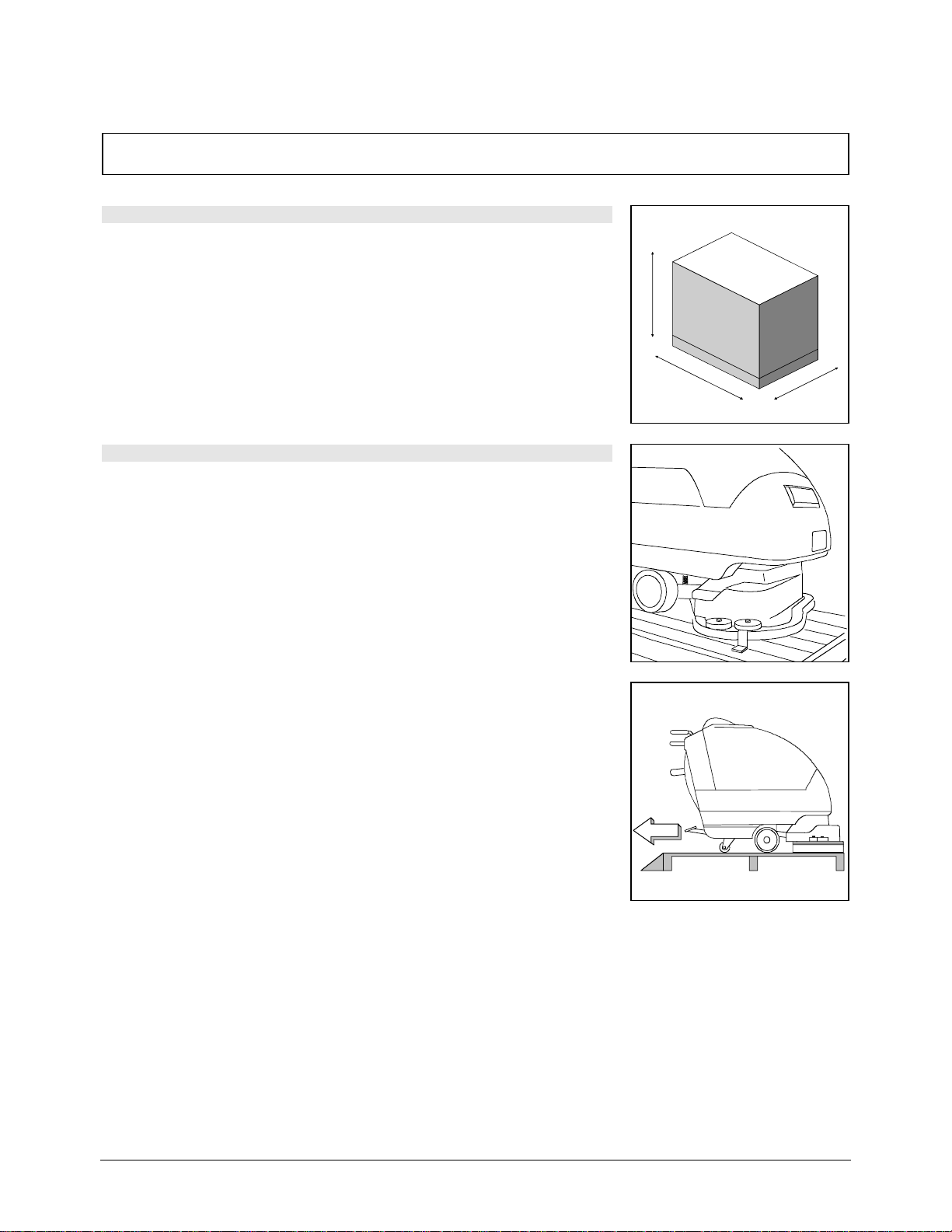
1. HANDLING OF THE PACKED MACHINE
The machine is packaged on a pallet for the handling with fork trucks. Do not
place more than two skids on top of each other. The total weight is 160 kg for
ST 726, 180 kg for ST 732.
The overall dimensions are:
ST 726 ST 732
A: 48.5” 48”
B: 28.5” 38”
C: 58.5” 67”
2. HOW TO UNPACK THE MACHINE
1. Remove the box from the skid
2. The machine is held in place with wooden blocks which block the wheels.
3. Remove the wooden blocks
C
B
4. Using a ramp, take the machine off of the skid by pushing it in reverse.
Avoid bumpin g th e br u sh head.
5. Keep the pallet for future transport if necessary.
6
Page 8

MACHINE PREPARATION
3. BATTERY INSTALLATION
The batteries must be fitted in the compartment under the recovery tank and
must be handled by using appropriate lifting equipment suitable both for the
weight and for the lifting system.
ATTENTION! When recharging the batteries be sure to follow the
manufacturer’s specifications.
Only trained staff may carry out the installation and maintenance
procedures. Please ensure all proper safety equipment is used
while installing or maintaining the batteries.
For the battery installation it is necessary to:
1. Lift the cover of the recovery tank (1)
2. Take off the suction cover (2) rotating it counter-clockwise
3. Lift the recovery tank from the side.
2
4. Make sure that the drainage hole placed on the bottom of the battery tray is
not covered.
5. Place the batteries inside the compartment
6. If the batteries are already charged, the machine connector can be
assembled to the battery connector. Otherwise proceed with the charging
process as indicated below
7. Reassemble the machine
4. CONNECTING THE BATTERY CHARGER
The connector for the battery charger is delivered with the machine and can
be found in the bag where this instruction booklet is found. It must be
assembled on the battery charger cables following the battery chargers
instructions
ATTENTION! This operation has to be carried out by trained
staff. A wrong or incomplete cable connection to the connector
can cause serious damage to persons, the electrical system of
the machine, and the batteries.
7
Page 9

MACHINE PREPARATION
5. RECHARGING THE BATTERIES
In order to prevent damage to the batteries, avoid over discharging them.
When the battery indicator flashes “0” the batteries should be connected to the
charger imm ediately.
NOTE: Never leave the batteries completely discharged, even if the machine
is not being used. When recharging the batteries, lift the tank. Every 20
charges check the level of the battery acid (Wet led acid only) and, if
necessary, top up with distilled water.
ATTENTION! For the daily charging routine of the batteries, follow
all of the instructions given by the manufacturer or from their
dealer. Trained staff must carry out all installation and maintenance
operations using the proper safety equipment.
ATTENTION! Danger of gas exhalations and emission of corrosive
liquids
ATTENTION! Fire danger: do not approach with free flames
6. CONNECTING THE BATTERY CONNECTOR
The machine connector (2) has to be connected to th e battery connector (1)
7. BATTERY INDICATOR
The battery ind ic ato r i s di git al wit h 5 p osi ti ons . T he num ber s, whi c h app ea r on
the display, show the approximate charge level.
4 = maximum charge, 3 = charge 3/4, 2 = charge 2/4, 1 = charge 1/4,
0 = (blinking) discharged batteries)
ATTENTION! When the indicator flashes “0” , the brushes
automatically switch off. This is to allow enough time to drive the
machine to the charging area.
8
Page 10

MACHINE PREPARATION
8. SQUEEGEE ASSEMBLY
The squeegee, which is packed separately from the machine, should be
assembled as shown in the figure. Insert the left squeegee pin (1) in the left
arm slot, then the right pin (2) into the right slot, paying attention to keep the
spring and the washer over the blade of the arm itself. To simplify this
operation the hand-wheel placed on top of the pin should be loosened when
installing the squeegee. Tighten the hand-wheel to lock the squeegee in
position.
Fit the squeegee hose into its coupling (3)
9. ADJUSTMENT SQUEEGEE HEIGHT
The squeegee has to be adjusted depending on the wear of the squeegee
blades. To adjust this, rotate the knob (1) of each wheel clockwise to lift the
squeegee and counter-clockwise to lower it.
Note: The right and left wheels must be adjusted at the same amount so that
the squeegee sits parallel to the floor.
1
3
2
10. ADJUSTMENT SQUEEGEE PITCH
During working operation, the rear blade has to be tilted backwards approx.
5mm across the whole length of the squeegee. The squeegee pitch
adjustment (1) should only be adjusted if the center of the squeegee is not
touching the floor properly. To tilt the squeegee down, turn the adjustment bolt
(1) counter-clockwise until the proper adjustment is reached. To tilt the
squeegee up, turn the adjustment bolt (1) clockwise until the proper
adjustment is reached. After the adjustment is made, remember to lock the
lock nut back in place on the adjustment bolt.
9
Page 11

MACHINE PREPARATION
11. BRUSH ASSEMBLY
1. Lift the brushes base using the pedal (1)
2. lock the lever in position (2)
3. Turn the key into position “0”.
ATTENTION! Always ensure that the power is off and the battery
connector is disconnected before mounting or dismounting the
brushes. Failing to do so can result in bodily injury.
4. With the brush base in the up position, insert the brushes into the seat of
the plate under the base until the three lugs fit into the holes of the plate.
Turn the brush so that the lugs are pushed towards their retaining springs
and locked in to place. The figure shows the direction to lock on the right
brush. When locking on the left brush, you will need to spin it the opposite
way.
2
1
5. You should swap the position of the brushes daily. If the brush bristles
have started to deform, they should be installed on the same side all of the
time to avoid excess load on the brush motor.
10
Page 12

MACHINE PREPARATION
12. RECOVERY TANK
Open the cover (1) and check that, the suction connection (2) is properly
connected by fitting the notches into its proper seat rotating it clockwise.
Check that the squeegee hose (3) is properly placed in to the tank and that
the plug of the recovery drain hose is closed.
13. SOLUTION FILTER
Check that the outer filter, placed between the valve and the solenoid valve, is
assembled correctly and t ha t it is clean. Remember to check this filter often.
2
3
14. FILLING THE SOLUTION TANK
Fill the solution tank with clean water at a temperature not more than 50°C
and add liquid detergent in the proper concentration following the instructions
of the manufacturer. Excess foam can damage the suction motor, so use only
the minimum amount of detergent necessary.
ATTENTION! Always use low foaming detergent. To avoid the
production of foam, before starting to clean, put a minimum
quantity of defoamer into the recovery tank. Never use pure acid.
11
Page 13

RULES OF SAFETY
The rules below must to be followed carefully in order to avoid damage to the operator a nd the mac hine.
Read the labels carefully on the machine. Do not cover them for any re ason and replace them immediately if
damaged
The machine must be used exclusively by authorized staff that has been trained for its use
Durin g use of the machine, pay attention to other people in the environment around you.
Do not mix different c hemicals
Do not place any liquid containers on the machine
The storage temperature has to be between -25°C and +55°C
Operating c onditions: room temperature between 0°C and 40°C with respective humidity between 30 and 95%
Do not us e the machine in explosive atmosphere
Do not us e the machine as a means of transport
Do not us e acid solutions which could damage the machine and/or the persons
Avoid working with the brushes down when the machine stands still, in order to prevent damaging the floor
Do not v ac uum flammable liquids
This appliance is not suitable for picking up hazardous dust
In c ase of fire, use a powder extinguisher. Do not use water
Do not strike shelvings or scaffoldings, where there is danger of falling objects
Adapt the working speed to the conditions
Do not us e the machine on areas having a higher gradient than the one stated on the number plate
When the machine is in parking position, remov e the key and engage t he park ing brak e
The machine has to carry out simultaneous operations of scrubbing and drying. Different operations have to be
carried out in areas which are not permitted for the passage of non employed staff. Signal the areas of moist
floors with suitable signs.
If the machine does not work properly, check by conducting simple maintenance procedures. Otherwise, it is
better to ask for NaceCare Solutions technical service.
Wher e parts are required, ask for ORIGINAL spare parts to an agent and/or to an authorized dealer
Us e only OE M brushes
In c as e of emergency, immediately engage the emergency brake
Remov e the key and/or remove the battery connector before any maintenance, cleaning or parts’ replacement is
done
Do not tak e off the pieces which require the use of tools to be removed
Do not wash the machine with direct water or with high water pressure nor with corrosive material
Ev ery 200 working hours have a machine check through a NaceCare Solutions service department
Be sure the recovery tank is empty before lifting it
In order to avoid scales on the solution tank filter, do not leave solution in the tank for extended periods.
Before using the machine, check that all doors and coverings are in their position as indicated in this use and
maintenance catalogue
12
Page 14

USING THE MACHINE
SET UP
1. Connect the machine connector to the battery connector(1)
2. Turn the key switch (2) into position I (clockwise). Immediately, the battery
indicator comes on (3)
1
3
3. Press the traction motor switch forward (1)
4. Press the brushes motor switch forward(2)
5. Press the suction motor switch forward(3)
6. Press the solenoid valve switch forward(4)
1
2
2
0
I
3
7. Adjust the quantity of the detergent by lever (1). Please keep in mind that,
the correct solution quantity depends always on the type of floor, the dirt
and the speed.
8. Lower the brush base using the pedal (2) and releasing the lever (3)
9. Lower the squeegee using the pedal (4) and unhook the lever (5)
10. Check that the parking brake (5) is released
10. Push the traction control lever (1) forward, so that the machine starts to
move forward and the brushes start to turn. Check that the quantity of
solution is sufficient and the squeegee dries the floor.
The machine is working now until the cleaning solution is used up.
4
1
5
4
1
6
3
2
13
Page 15

USING THE MACHINE
MOVEMENT
Forwards: The traction of the machine is obtained through a flat
belt tensioning system.The movement speed is proportional to the
force applied to the lever.
Reverse movement: To rever se the machine, y ou must press an d
hold the reverse switch (2) and push the drive lever (1) forward.
The reverse switch must be held down for this process.
ATTENTION! When reversing, make sure that the squeegee is
lifted.
1
BRAKE
The machine is equipped with two braking systems. A working
brake controlled through the drive lever (1) and an emergency and
parking brake controlled through the lever (2).
In order to reduce the speed let the control lever (1) free.
If an emergency stop is required, pull the speed control lever (1)
back and push the emergency brake (2) downwards. These steps
will lock the traction of the machine.
2
14
Page 16

USING THE MACHINE
RECOVERY TANK IS TOO FULL
The machine is equipped with a float, which intervenes when the
recovery tank is full causing the closure of the suction s ystem. If
you hear the vacuum motor suddenly change in pitch, the recovery
tank is full and needs to be emptied.
ATTENTION! This operation has to be carried out using
gloves to protect the operator from contact with
dangerous solutions.
15
Page 17

ON COMPLETION OF WORK
Having finished the job and before any type of maintenance is
done:
1. Close the water valve using the lever (1)
2. Lift the brush base using the pedal (2) and lock the lever (3).
3. Lift the squeegee using the pedal (4) and lock the lever (5).
4. Activate the parking brake by pushing the lever (6) downwards.
1
5
6
3
5. Switch off the solenoid valve switch and the suction motor
switch (1)
6. Switch off the brush motor switch (2)
7. Bring the machine to a suitable place for draining
8. Switch the traction switch in to the neutral position(3)
9. Turn the key (4) into position O (counterclockwise)
10. Activate the parking brake
1
3
4
2
2
0
I
4
11. Release the hose placed on the rear panel
12. Unscrew the drain plug and empty the tank
ATTENTION! This operation has to be carried out
using gloves to protect from contact with dangerous
solutions.
13. Take off the brushes and clean them with water (for the brush
disassembly please read further on “DISASSEMBLING THE
BRUSHES”)
16
Page 18

DAILY MAINTENANCE
CLEANING RECOVERY TANK
1. Re lease the hose placed on th e rear panel
2. Unscrew the exhaust plug and empty the tank completely
ATTENTION! This operation has to be carried out
using gloves to protect from contact with dangerous
solutions.
3. Lift the cover of the recovery tank (1)
4. Take off the suction plug rotating it counter-clockwise (2)
5. Take off the filter
6. Rinse the tank and float cage with clean warm water
17
Page 19

DAILY MAINTENANCE
CLEANING SUCTION FILTER
1. Lift the cover
2. Take off the suction plug by rotating it counter-clockwise
3. Remove the filter
4. Clean the filter with clean warm water
5. Wash all of the components thoroughly
CLEANING SOLUTION FILTER
1. Close the water valve
2. Unscrew the filter located under the rear left side of the machine
3. Extract the cartridge from the filter and clean it with warm water
4. Reassemble the water filter
CLEANING THE SQUEEGEE
In order to have the best drying results, check that the squeegee is always
clean.
To clean the squeegee, you must:
1. Take off the hose (1) from the squeegee
2. Release the squeegee
3. Clean the inside of the squeegee thoroughly
4. Clean the squeegee blades thoroughly
5. Reassemble the squeegee to the machine
REPLACING THE REAR SQUEEGEE BLADE
If the rear squeegee blade is worn and does not dry well, you must change
the drying edge proceeding as follows:
1. Push and turn the support plates (1) as shown in the figure.
2. Slip off the rubber blade and the rubber itself
3. Turn the rubber (2) upside-down and if necessary, replace it
4. Reassemble the squeegee
5. Adjust the squeegee height depending on the wear of the blade (see
“ADJUSTING THE SQUEEGEE”)
1
2
3
18
Page 20

DAILY MAINTENANCE
REPLACING THE FRONT SQUEEGEE BLADE
If the front squeegee rubber is worn, a good suction is not achieved and
therefore the machine does not dry well. In that case proceed as follows with
the replacement:
1. Take off the squeegee loosening the register (1)
2. Unscrew the nuts, which hold the front rubber plate of the squeegee.
3. Remove the front rubber plate.
4. Slip off the rubber and replac e it
5. Reassemble following these steps in reverse
BRUSH REMOVAL
To remove the brushes, follow these steps:
1. Lift the brush base using the pedal (1) and lock the lever (2)
2. Engage the parking brake (3)
3. Turn the key off and remove it from the switch
4. Remove the battery connector
ATTENTION! Removing the brushes while the machine has
power to it can cause serious bodily injury.
1
3
2
0
I
5. Unhook the splash skirt on the brush base
6. Rotate the brush until it comes off from the brush plate seat as shown in
the figure.
19
Page 21

WEEKLY MAINTENANCE
CLEANING THE SQUEEGEE HOSE
Weekly or if the suction seems to be poor, check that the squeegee hose is
not plugged with debris. Clean it as follows:
1. Take off the hose from the squeegee
2. Take off the other end from the recovery tank
3. Wash the inner part of the hose with warm water from the side where it is
being connected to the tank
ATTENTION! Do not wash the hose, which goes from the
suction motor to the suction plug.
BRAKE ADJUSTMENT
Once a week check the distance between the brake pads and the wheels.
Push the drive lever (1) forward until the handle bar is touched, unscrew the
nuts and adjust the brake pads at a distance of 1mm from the wheels.
REPLACING THE SPLASH GUARD
Check the condition of the splash guard. If it is necessary, to replace it,
proceed as follows:
1. Unhook the two clips (1)
2. Take off the splash guard and replace it with a new one
3. Re-attach the clips
11
2
20
Page 22

TROUBLE SHOOTING GUIDE
INSUFFICIENT WATER ONTO THE BRUSHES
1. Make sure that the key (1) is on position I
2. Make sure that the switches for the solenoid, and the brushes are on (2)
3. Make sure that the traction motor switch is in the forward position (3)
4. Make sure that the solution valve (4) is open
5. Make sure that there is water in the solution tank
6. Make sure that the filter is not plugged
0
I
21
3
THE MACHINE DOES NOT CLEAN WELL
1. Chec k the condition of the brushes and replace them if necessary. (the
brushes have to be replaced when the length of the bristles is less than
15mm)
2. Chec k that the detergent used is in the right concentration and suitable
for the cleaning application
THE SQUEEGEE DOES NOT DRY WELL
1. Check that the suction motor switch is on
2. Check and adjust the squeegee height and its inclination
3. Check the squeegee blades, clean them or replace them if they are worn
4. Check that the recovery tank is empty
5. Check that the squeegee hose is correctly fitted on the recovery tank
6. Check that the suction hose is correctly fitted on the suction motor and on
the filter opening
7. Check that the suction filter is clean
8. Check that the plug on the drain hose is tight
4
EXCESSIVE FOAM IN THE RECOVERY TANK
Check that a low foam detergent has been used. If required, add a small
quantity of antifoam l iquid into the recovery tank.
Remember that, when the floor is not very dirty, more foam is generated. In
this case dilute the detergent by adding more water to the solution tank.
21
 Loading...