

Page 1
ST 360
NaceCare Solutions
1205 Britannia road east
Mississauga, Ontario, Canada
L4W 1C7
Toll Free: 1 800 387 3210
Toll Free Fax: 1 800 709 2896
Page 2

ST360_V05-2
TABLE OF CONTENTS
....................................................................................................................................................................... 1
TABLE OF CONTENTS ...................................................................................................................................2
DELIVERY OF THE MACHINE.........................................................................................................................3
INTRODUCTION..............................................................................................................................................3
TECHNICAL DATA ..........................................................................................................................................4
SYMBOLS USED ON THE MACHINE...............................................................................................................5
PREPARATION OF THE MACHINE .................................................................................................................6
MOVING THE MACHINE WHEN PACKED............................................................. 6
UNPACKING THE MACHINE....................................................................... 6
CONNECTING THE BATTERY CHARGER ............................................................ 7
RECHARGING THE BATTERIES ................................................................... 7
BATTERY LEVEL INDICATOR ..................................................................... 7
SQUEEGEE ................................................................................... 8
FITTING THE DISC BRUSH ....................................................................... 9
DETERGENT SOLUTION ......................................................................... 9
RECOVERY TANK .............................................................................. 9
GENERAL SAFETY RULES...........................................................................................................................10
CONTROLS ....................................................................................................................................................11
MAIN CONTROLS.............................................................................. 11
OPERATING THE GEAR LEVERS ................................................................. 13
SUCTION .................................................................................... 15
HORN....................................................................................... 15
SOLUTION LEVEL ............................................................................. 15
UPON COMPLETION OF WORK....................................................................................................................16
DAILY MAINTENANCE .................................................................................................................................. 17
CLEANING THE RECOVERY TANK ................................................................ 17
CLEANING THE SQUEEGEE ..................................................................... 17
REPLACING SQUEEGEE RUBBER BARS ........................................................... 18
RELEASING THE DISC BRUSH ................................................................... 18
CLEANING THE FILTER AND THE SOLUTION TANK................................................... 18
CLEANING THE SUCTION HOSE .................................................................. 19
CLEANING THE SUCTION MOTOR FILTER .......................................................... 19
OPERATION CONTROL ...............................................................................................................................20
NOT ENOUGH WATER ON THE BRUSH ............................................................ 20
MACHINE DOES NOT CLEAN EFFECTIVELY ........................................................ 20
SQUEEGEE DOES NOT DRY PERFECTLY .......................................................... 20
SUCTION DOES NOT WORK ..................................................................... 21
BRUSH MOTOR DOES NOT WORK ................................................................ 21
TRACTION MOTOR DOES NOT WORK ............................................................. 21
TOO MUCH FOAM FORMATION .................................................................. 21
THERMAL PROTECTIONS ....................................................................... 21
TRANSPORTING THE MACHINE........................................................................................................................................... 22
2
Page 3
ST360_V05-2
Delivery of the machine
When the machine is delivered, please check
immediately that all materials match the delivery
documents and that the machine has not been
damaged during transport. If so, ask your shipping
agent to assess the extent of the damage and
inform our customer care service at once. Prompt
and appropriate action is the only way to obtain the
missing parts and to be able to claim damages.
3
Page 4

TECHNICAL DATA
4
ST360
TECHNICAL DATA UNIT
Working width Inches 21"
Squeegee width Inches 25.5"
Working capacity Sq feet/h 31,500
Brushes Inches 1 x 21"
Brush rpm RPM 200
Brush pressure LBS 100
Brush motor Volts V 24
Brush motor Watts W 400
Traction speed mph 0 - 4.5
Max grade capability % 10%
Suction motor Volts V 24
Suction motor Watts W 480
Solution tank Gallon 24
Recovery tank Gallon 27
Turning radius Inches 53"
Machine length Inches 48.5"
Machine width Inches 25.5"
Machine height Inches 62"
Batteries (No.) V/AH 24/240AH 4x6V
Battery weight Lbs 71lbs x 4
Machine weight without batteries Lbs 496
ST360_V05-2
Page 5
ST360_V05-2
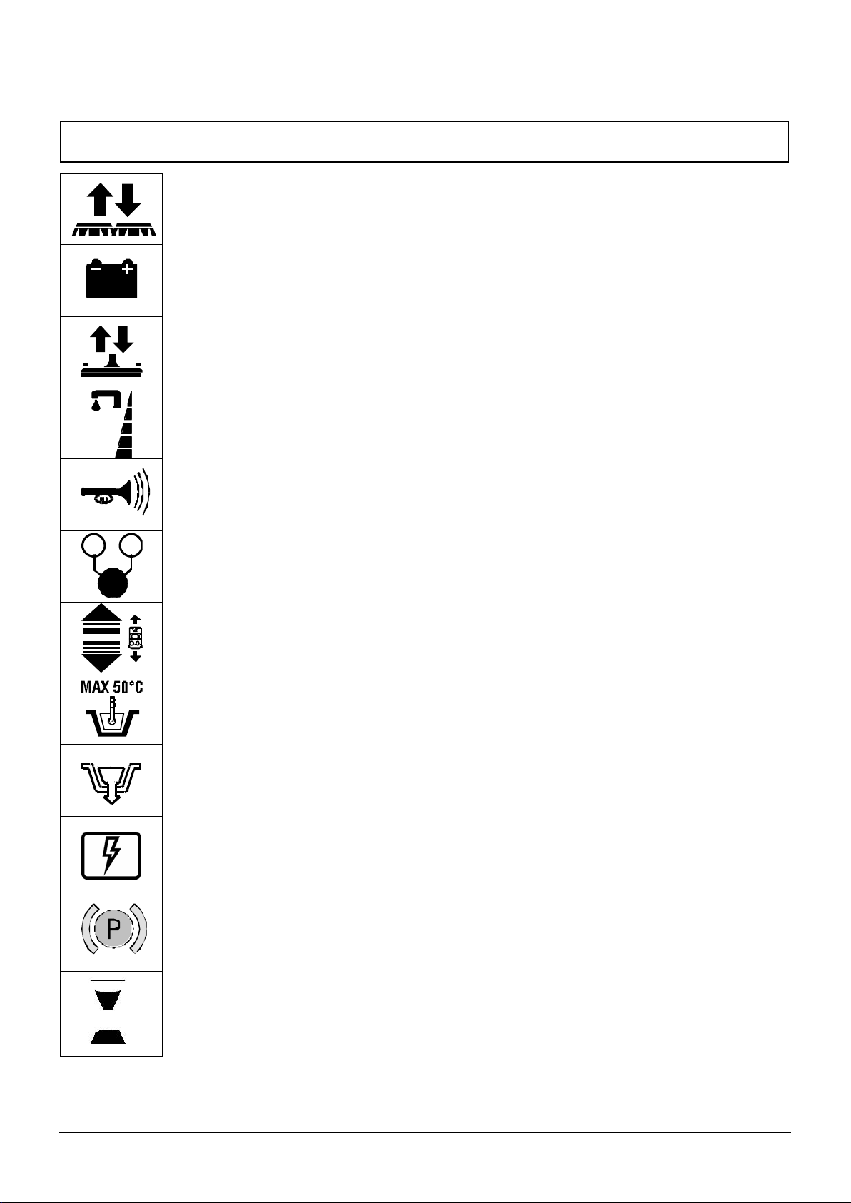
SYMBOLS USED ON THE MACHINE
Symbol for brush head up/down.
It indicates the brush head up/down pedal.
Symbol for battery charge level.
Symbol for squeegee up/down.
It indicates the up/down pedal of the squeegee.
Symbol for water flow.
Symbol for the horn button.
OFF/0 ON/1
Symbol for on/off switch.
Symbol for forward and reverse switch.
Its position shows the direction of the machine, either forwards or reverse.
Symbol for maximum temperature of solution.
Symbol for drain hose on the recovery tank.
Symbol for fuse panel
Symbol for levers in brake position
Symbol for the hourmeter
5
Page 6
ST360_V05-2
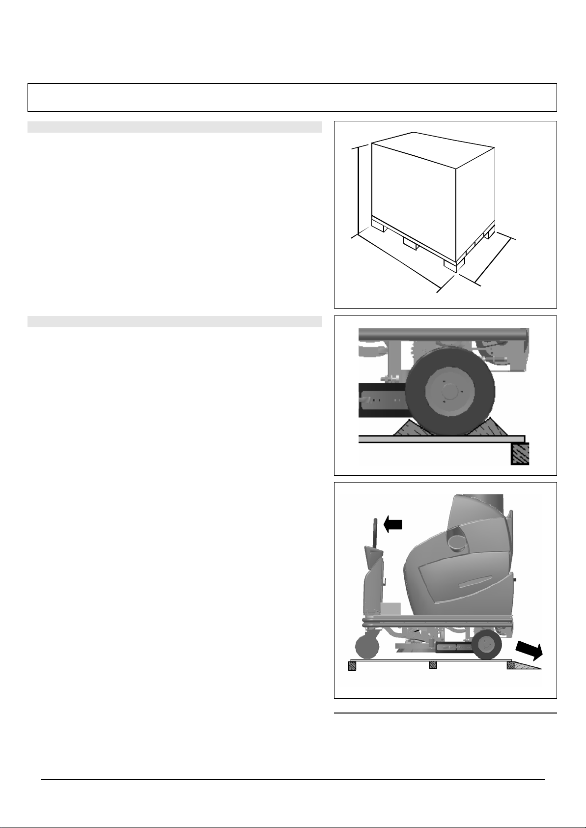
PREPARATION OF THE MACHINE
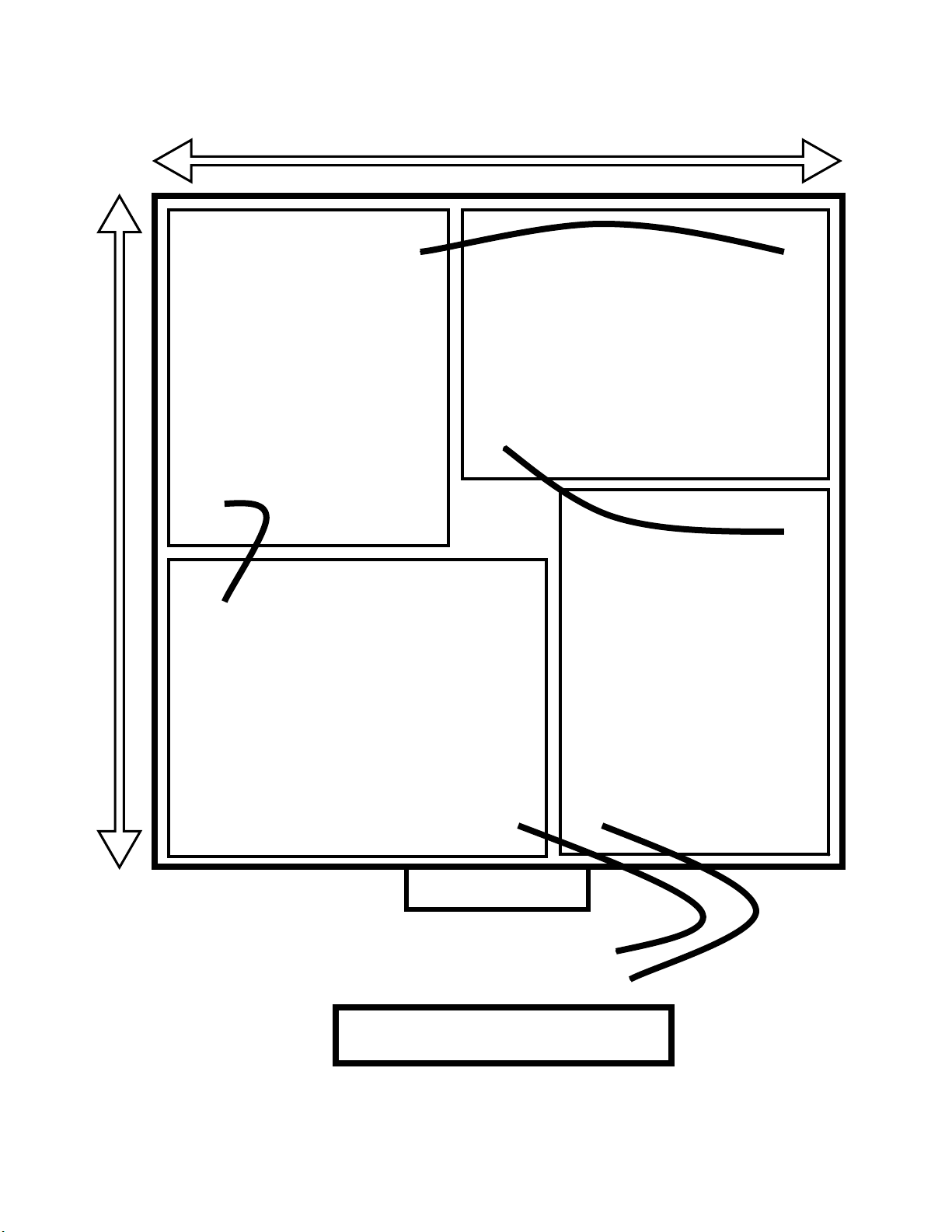
MOVING THE MACHINE WHEN PACKED
The machine comes in special packaging which includes a
platform for fork -lift transport. Do not place skids one on top
of the other.
The overall weight is 540Lbs.
Packing size is:
A : 60"
B : 29"
C : 52.5"
A
C B
UNPACKING THE MACHINE
Remove the box.
The machine is fixed to the skid by wheel -blocks.
Remove the wheel blocks.
Push the machine backwards off of the skid using a ramp.
Avoid hitting the brush head on the skid.
Keep the skid for future transport.
The suction head, is located inside the
battery compartment.
NOTE: to move the machine without batteries push the
drive levers forward.
6
Page 7
ST360_V05-2
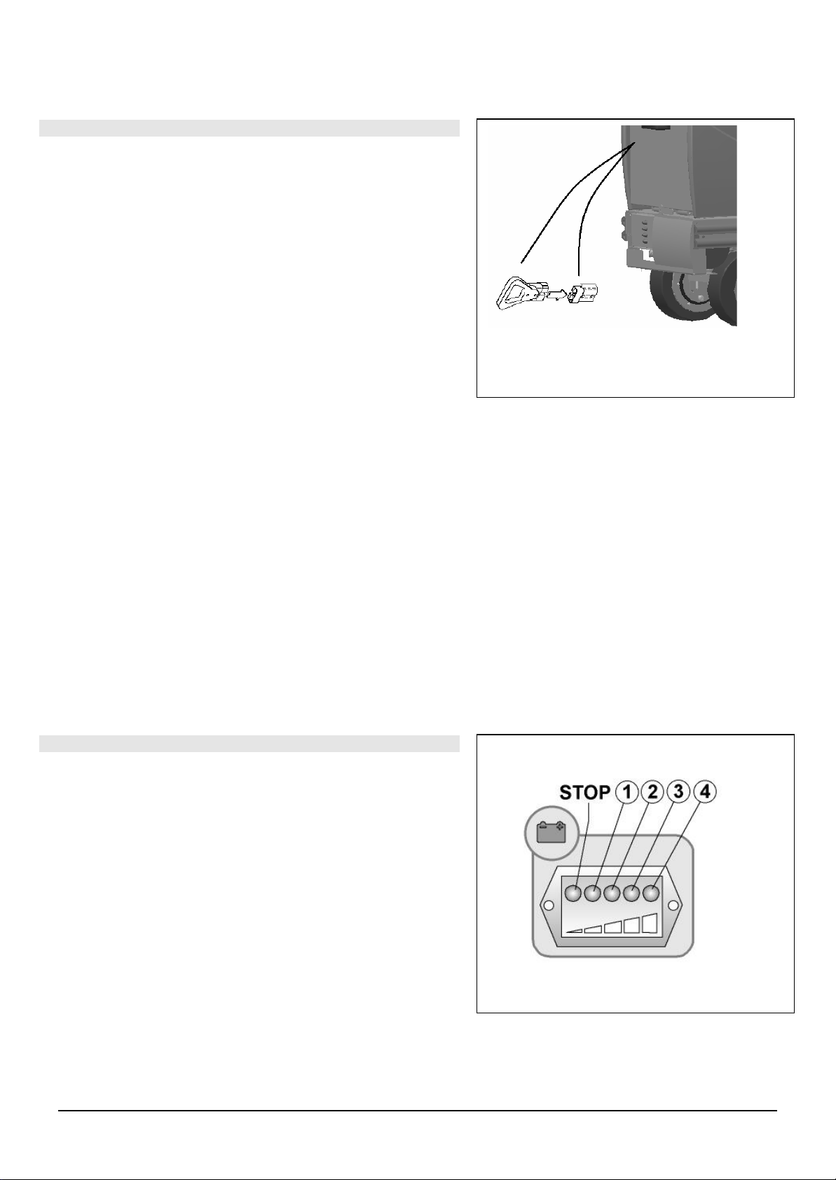
CONNECTING THE BATTERY CHARGER
The connectors are fitted on the battery compartment. Plug the
connector of the battery charger cables into the socket on battery
compartment. The battery connector is delivered inside the bag
where you found this instruction booklet.
BATTERY LEVEL INDICATOR
The battery level indicator is operated by a microprocessor. The
LEDs display the approximate level of charge:
4 = max. charge level, 3 = ¾ charge level,
2 = ½ charge level, 1 = ¼ charge level,
0 = flat batteries (blinking light).
ATTENTION: a few seconds after the “=” is shown, the brush
motor switches off automatically. However, with the residual
charge, the floor can be dried before recharging
7
Page 8
17¾”
-
17 ¾”
+
-
+
+
-
+
TO MACHINE
-
REAR OF BATTERY BOX
NOTE: Battery box will accept Trojan T125 Batteries (10 3/8” L x 7 3/8” W)
Page 9

8
PREPARATION OF THE MACHINE
1 2
1
ST360_V05-2
SQUEEGEE
The squeegee is supplied already assembled on the machine and with the
adjustments made during machine testing.
When operating the machine, the rear rubber should be slightly tilted back
5mm all along its length. you can use the squeegee on all 4 edges before
replacing it with a new one.
To adjust the squeegee blade down, just tilt back the squeegee body by
turning the knobs counter-clockwise. To adjust the squeegee blade up,
turn the knobs clock-wise. When adjustment is completed, thighen the lock-nut.
To release the squeegee from the machine, use the lever (1) and the
squeegee is immediately released from its holder. Disconnect the
suction hose and push it towards the inside of the machine to release the
opposite side.
Page 10

9
PREPARING THE MACHINE
ST360_V05-2
FITTING THE DISC BRUSH
1. With the brush head lifted, centre the brush under the brush deck
2. When lowering the brush head, the brush will lock automatically.
DETERGENT SOLUTION
Fill up the solution tank with fresh water at a temperature not
exceeding 50 °C and add the liquid detergent according to the
concentrations and instructions that are provided by the
manufacturer.
NOTE: Always use low-foam detergents. To be sure to avoid any
foam formation, before starting to operate, pour a minimum quantity
of antifoaming agent into the recovery tank. Do not ever use pure
acids.
RECOVERY TANK
Make sure the vacuum unit is properly fitted and the drain hose
cap is closed.
Page 11

10
GENERAL SAFETY RULES
ST360_V05-2
Keep to the following rules in order to prevent any operator injury or machine damage.
r Read thoroughly the labels on the machine, do not cover them for any reason and replace them immediately if
they are damaged
r The machine should be operated only by authorised and trained personnel
r When operating the machine, beware of other people and especially to children
r Do not mix different types of detergent in order to prevent formation of harmful gases
r No Do not place any liquid container onto the machine
r Storage temperature should be between -25°C and +55°C
r The optimum operating temperature should be between 0°C and 40°C
r The humidity level should be between 30 and 95%
r Do not operate the machine in explosive environment
r Do not use the machine as means of transport
r Do not use any acid solution which could damage the machine
r Stop brush rotation when the machine is not moving to prevent floor damag e
r Avoid suction of inflammable liquids
r In the event of fire, use powder extinguishers. Do not use water.
r Do not bump against shelving or scaffolding to prevent any risk of object falling
r Adjust operating speed to wheel grip conditions
r Do not exceed the m aximum stated gradient to avoid instability
r When the machine is parked, take the key out
r The machine has to scrub and dry at the same time. If otherwise operated, cleaning tasks should only take
place in areas that are restricted to authorised personnel. Mark the wet floor areas with proper signs
r Should any anomalies be detected in machine operation, make sure they are not due to lack of ordinary
maintenance. Otherwise, ask the Fimap customer care service for assistance.
r Should any part be replaced, ask an authorised dealer and/or retailer for ORIGINAL spare parts.
r For any maintenance procedure, unplug the machine from the mains supply.
r Do not remove any protection which requires the use of tools to be removed
r Do not wash the machine with direct jets of water or under pressure, nor with corrosive substances.
r Every 200 operating hours have the machine checked by a Fimap customer care service
r The machine doesn’t cause any harmful vibration
r In order to prevent the solution tank filter from developing scaly deposits, do not pour in the detergent solution
hours before operating it.
r Before operating the machine, make sure that all caps and covers are properly positioned as indicated in this
operator’s manual.
r Before lifting the recovery tank, make sure it is empty.
r Dispose of any consumables in strict accordance with the relevant regulations in force.
r When, after years of valuable usage, you have to dispose of your FIMAP machine, make sure you dispose
correctly of all the materials it consists of, especially oils, batteries and electrical components considering that
the machine itself has been manufactured with completely recyclable materials.
r Attention: reconnect all electric connections after every maintenance procedure.
r The machine is not intended for children nor for unsupervised use by persons whose physical, sensory or
mental conditions could make the use of the machine unsafe. Keep the machine away from children.
Page 12

11
CONTROLS
2 1
3 6
7
9 8
10
11
10
ST360_V05-2
MAIN CONTROLS
1. Horn
2. Digital hourmeter
3. Battery level indicator
4. On/Off key switch
5. Forward/reverse switch
6. Forward/reverse levers
7. Solution lever
4
5
8. Squeegee control pedal: the
squeegee is working when the
pedal is lifted.
9. Pedal for right wheel directional
lock.
10. Brush control pedal, the brush is
working when the pedal is lifted.
11. Pedal for left wheel directional
lock.
12. Button to de-activate the vacuum motor.
Page 13

ST360_V05-2
OPERATING
Follow the operations as instructed under PREPARATION OF THE
MACHINE
1. Plug in the battery connector
2. Sit on the seat
3. Turn the key switch on.
4. Drop the brush deck down and the vacuum motor will start
automatically.
5. Open the tap by turning the knob counter clock-wise. Water only
flows when the brush motor is on.
6. To lower the brush head, push the pedal left and up. Brush and
suction start automatically. For higher pad pressure, lift the pedal
further until it locks in place. To lift the brush head, push the
pedal down until it locks in place.
7. To lower the squeegee, push the pedal right and up. To lift it, press
the pedal down until it locks in place.
12
Page 14

1
ST360_V05-2
OPERATING
OPERATING THE DRIVE LEVERS
Each lever is directly connected to the corresponding traction wheel
(right lever with right wheel and vice-versa).
Operating in forward gear:
1. Press the forward switch on the instrument board
2. Push both levers forwards simultaneously
To turn right, move the left lever fo rwards and the right one
backwards.
To turn left, move the right lever forwards and the left one backwards
To brake, pull back both levers simultaneously.
Operating in reverse gear:
1. Press the switch on the instrument board
2. Push both levers forward simultaneously
13
Page 15

14
ST360_V05-2
To turn right, move the left lever forwards and the right one
backwards.
To turn left, move the right lever forwards and the left one backwards.
These pedals are meant to lock the direction of the front wheels to
ensure straig ht drive when operating in forward or reverse gear.
NOTE: the machine is fitted with a deadman microswitch. The
machine does not works if the operator is not seated properly.
Page 16

1
ST360_V05-2
OPERATING
SUCTION
The vacuum motor starts automatically as the squeegee is lowered.
The motor does not switch off automatically when the squeegee is
lifted to prevent any water leaking from the suction hose. Wait a few
seconds and press the button (1) on the vacuum unit.
HORN
The machine is fitted with a horn switch. To sound the horn, press the
button as shown in the picture.
SOLUTION LEVEL
The solution tank has 3 water level indicators:
MIN
MED
MAX
MAX
MED
MIN
15
Page 17

16
UPON COMPLETION OF WORK
ST360_V05-2
Upon completion of work and prior to any type of maintenance
procedure, carry out the following operations:
1. Close the water valve
2. Lift the brush head
3. Lift the squeegee
4. Switch the suction motor off
5. Take the machine where you intend to drain the water out
6. Turn the key to “OFF”
Take the hose off the hook, unscrew the drain plug and empty the
recovery tank. To make this operation easier, keep the hose
higher than the tank water level with one hand and with the other
hand unscrew the knob and take off the cap. By slowly lowering the
hose, the liquid will come out at the desired speed. Do this only when
wearing protection gloves to prevent contact with dangerous
solutions.
When the machine is not operating lift the squeegee to prevent
rubber bars from losing their shape.
Release the brush and clean it with a hose (For brush release,
see the following chapter “BRUSH RELEASE”).
Page 18

ST360_V05-2
DAILY MAINTENANCE
CLEANING THE RECOVERY TANK
Empty the tank through the drain hose. Turn the knob a few turns to
unscrew it and remove the plug.
CLEANING THE SQUEEGEE
Clean the squeegee with a hose. Check for rubber blade wear
conditions and, if necessary, turn or replace them. Accurate cleaning of
the whole suction assembly ensures longer suction motor life.
17
Page 19

DAILY MAINTENANCE
1 3
2 4
ST360_V05-2
REPLACING SQUEEGEE RUBBER BARS
If the squeegee blades are worn out and do not dry properly,
change the drying side as follows:
Pull the squeegee assembly out as illustrated un der
“PREPARATION OF THE MACHINE”
Unlock the clamp (1) between the two rear blades
Pull out the blades (2/3) and the rubber bar (4)
Flip the rubber blade or, if necessary, replace it
Adjust squeegee height as illustrated under “HEIGHT
ADJUSTMENT OF THE SQUEEGEE SUPPORT” at chapter
“PREPARATION OF THE MACHINE”
Reassemble it all by following the above procedure in reverse
RELEASING THE DISC BRUSH
1. Turn the key to “OFF” and remove it from the instrument board.
(releasing the brush when the machine is on may cause serious
injury)
2. Disconnect the battery connector
3. Lift the brush head
4. Keeping the brush head lifted, rotate the brush to release it
from the brush holder plate as illustrated in the picture.
CLEANING THE FILTER AND THE SOLUTION TANK
Close the solution tap:
1. Unscrew the solution filter to empty the tank
2. Remove the cartridge and clean it
Reassemble it all by following the above procedure the other way
round
18
Page 20

WEEKLY MAINTENANCE
2
ST360_V05-2
CLEANING THE SUCTION HOSE
1. In case of po or suction, make sure the suction hose is not
clogged. Clean it with a garden hose from where
the hose is connected to the tank.
CLEANING THE SUCTION MOTOR FILTER
1. Disconnect the main connector between the suction cover and the
recovery tank
2. Remove the suction unit from the tank.
3. With a circular movement, remove the black cover (1).
4. Remove the filter (2) and clean it thoroughly with a garden hose.
5. Reassemble it all by following the above procedure in reverse
1
19
Page 21

20
OPERATION CONTROL
ST360_V05-2
NOT ENOUGH WATER ON THE BRUSH
1. Make sure the tap is open
2. Make sure there is water in the solution tank
3. Clean the solution filter
MACHINE DOES NOT CLEAN EFFECTIVELY
1. Check for brush wear and, if necessary, replace it (the brush should
be replaced as the bristles are about 15 mm long).
2. Use another type of brush and not the standard one. For cleaning
tasks on floors with stubborn dirt, special brushes are
recommended, which can be supplied on request according to
individual requirements.
SQUEEGEE DOES NOT DRY PERFECTLY
1. Make sure the squeegee is clean
2. Adjust the height of the squeegee support (see under
“PREPARATION OF THE MACHINE”)
3. Clean the whole suction unit (see under “WEEKLY
MAINTENANCE”)
4. Replace the rubber blades, if worn out
Page 22

21
OPERATION CONTROL
ST360_V05-2
SUCTION DOES NOT WORK
1. Make sure the connector of the suction unit is properly connected.
2. Make sure that thermal protection has not been activated (see
under THERMAL PROTECTION).
BRUSH MOTOR DOES NOT WORK
1. Make sure the brush head was lowered.
2. Make sure that batteries are charged by checking on the indicator.
3. Make sure that thermal protection has not been activated (see
under THERMAL PROTECTION).
TRACTION MOT OR DOES NOT WORK
4. Make sure that batteries are charged by checking the indicator.
1. Make sure that thermal protection has not been activated (see
under THERMAL PROTECTION).
TOO MUCH FOAM FORMATION
Make sure that low-foam detergent has been used. If necessary, add a
minimal quantity of antifoaming agent into the recovery tank.
Keep in mind that there is more foam formation when the floor is not
very dirty. In this event, use a more diluted detergent solution.
THERMAL PROTECTIONS
There is a THERMAL PROTECTION system for the following
functions:
1. Main.
2. Suction.
3. Brushes.
4. Traction.
Should any of these functions stop, resume operation by pressing the
relevant button.
The breaker panel is built-in to the rear left of the machine.
1
2
3
4
Page 23

ST360 LOADING AND UNLOADING USING A RAMP
23 ST360_V05-2
When going down a ramp with the ST360, always go down the
ramp forwards.
Note: If you must unload the
machine in reverse, stand in
front of the machine and pull
the drive levers towards you.
Push the machine down the
ramp in reverse while
continuing to hold the drive
levers. Never
machine down a ramp in
reverse. Also, ensure that the
battery box is well secured
drive the
Never attempt to drive down a ramp backwards with the ST360.
If the brakes are applied while driving down a ramp in reverse,
the machine may tip and cause serious injury to the operator and
bystanders.
Page 24

ST360 TRANSPORT INSTRUCTIONS
24 ST360_V05-2
When transporting the ST360, to prevent any damage to the machine follow these
guidelines:
1. Make sure that both the solution and recovery tanks are empty.
2. Ensure the machine is strapped down and well secured inside the trailer.
3. Remove the vacuum head to prevent any possible damage.
4. Transport the battery box and trolley separately, or put one strap around the entire
machine (from front to back) to prevent the battery box from coming loose during
transport.
5. If transporting the battery box on the trolley, lock the trolley wheels and ensure
the trolley is well secured in the trailer.
6. Ensure that the brakes on the machine are in the locked position using the locking
rod provided with the machine.
 Loading...