

Page 1

GBGB
GB
GBGB
High PrHigh Pr
High Pr
High PrHigh Pr
essuressur
essur
essuressur
e Cleanerse Cleaners
e Cleaners
e Cleanerse Cleaners
( 110-127 V / 60 Hz )
( 220-240 V / 50/60 Hz )
Operating manualOperating manual
Operating manual
Operating manualOperating manual
Read and conform Read and conform
Read and conform
Read and conform Read and conform
safety instructions safety instructions
safety instructions
safety instructions safety instructions
before use before use
before use
before use before use
Page 2

DescriptionDescription
Description
DescriptionDescription
Dear customer
We would like to congratulate you on your new high pressure cleaner with integrated
undercarriage and integrated hose drum and to thank you for the purchase.
To ease your introduction to the use of the cleaner, we have provided the following
pages of explanations, tips and hints, which we ask you to read before using for the
first time.
The equipment will assist you professionally in all cleaning tasks, e.g.:
- facades
- flagstones
- terraces
- vehicles of all types
- containers
- machines etc.
- removing of
old paint
Technical
data
Operating pressure,
steplessly adjustable
Perm. overpressure
Water output
Hot water input
Suction height
High pressure hose
with hose drum
Electrical ratings
Connect. wattage input
Weight
Dimens. with mounted
Handel in mm
Sound level acc.to 45635
with dirtkiller
Guaranteed sound level L
Recoil at lance
Vibrations at lance
Order n°:
K 1150 / K1120
with dirtkiller
K 1150 T
Minimum quantity of water to be led to the equipment (see page 7)
*
*
(min. 1-8 bar)
output
WA
Permissible tolerance for figures ± 5 % in acc. with VDMA uniform sheet 24411
Kränzle
K1150
K1150 T
10 - 130 bar (
1900 PSI )
150 bar
at 2800 rpm
10 l/min
max. 60 °C
1.0 m
10 m
15m
220 - 240V ;
50 Hz ; 12,5 A
P1: 2.8 kW
P2: 2.0 kW
22 kg (K 1150 )
26 kg (K 1150 T)
300 x 330 x 800
88 dB (A)
90 dB (A)
92 dB (A)
approx. 27 N
1,9 m/s²
41.211
41.211 1
41.210 1
Kränzle
K1120-60Hz
K1120T-60Hz
10 - 95 bar
( 1400 PSI )
120 bar (1800PSI)
at 1700 rpm
8, 3 l/min
max. 60 °C
2.0 m
10 m
15m
110 - 127 V ;
60 Hz; 6,7 A
P1: 1.65 kW
P2: 1.35 kW
22 kg ( K1120 )
26 kg ( K1120 T )
300 x 330 x 800
89 dB (A)
84 dB (A)
92 dB (A)
approx. 22 N
1,9 m/s²
41.213
41 2131
41.212 1
Kränzle
K1150-60Hz
K1150T-60Hz
10 - 130 bar
( 1900 PSI )
150 bar ( 2200 PSI )
at 3400 rpm
10 l/min
max. 60 °C
1.0 m
10 m
15m
220 - 240 V ;
60 Hz; 8,7 A
P1: 2.8 kW
P2: 2.0 kW
22 kg ( K 1150 )
26 kg (K1150 T )
300 x 330 x 800
93 dB (A)
93 dB (A)
92 dB (A)
approx. 32 N
1,9 m/s²
41.211 2
41.211 3
41.210 3
2
Page 3
DescriptionDescription
Description
DescriptionDescription
3
3
22
2
22
WaterWater
Water
WaterWater
99
9
99
55
5
44
4
44
3
3
55
88
8
88
77
7
77
33
3
33
66
6
66
11
1
11
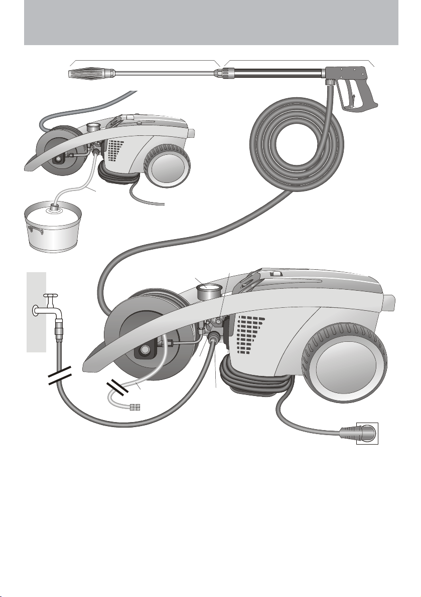
Construction
The KRÄNZLE 1120 / 1120 T + 1150 / 1150 T - high pressure cleaners are
mobile machines. The design can be seen from the diagram.
Item
66
High pressure injector forHigh pressure injector for
6
High pressure injector for
66
1 Water inlet connection with filter1 Water inlet connection with filter
1 Water inlet connection with filter
1 Water inlet connection with filter1 Water inlet connection with filter
2 Suction hose with filter (special2 Suction hose with filter (special
2 Suction hose with filter (special
2 Suction hose with filter (special2 Suction hose with filter (special
accessory) Order no. 15.038 3 accessory) Order no. 15.038 3
accessory) Order no. 15.038 3
accessory) Order no. 15.038 3 accessory) Order no. 15.038 3
3 High pressure pump3 High pressure pump
3 High pressure pump
3 High pressure pump3 High pressure pump
4 Press. gauge with glycerin filling4 Press. gauge with glycerin filling
4 Press. gauge with glycerin filling
4 Press. gauge with glycerin filling4 Press. gauge with glycerin filling
5 Unloader valve - safety valve5 Unloader valve - safety valve
5 Unloader valve - safety valve
5 Unloader valve - safety valve5 Unloader valve - safety valve
High pressure injector forHigh pressure injector for
cleaningcleaning
cleaning
cleaningcleaning
77
High pressure hoseHigh pressure hose
7
High pressure hose
77
High pressure hoseHigh pressure hose
88
Spray gunSpray gun
8
Spray gun
88
Spray gunSpray gun
99
Interchangeable lance with reg.Interchangeable lance with reg.
9
Interchangeable lance with reg.
99
Interchangeable lance with reg.Interchangeable lance with reg.
nozzlenozzle
nozzle
nozzlenozzle
agentsagents
agents
agentsagents
3
Page 4

DescriptionDescription
Description
DescriptionDescription
Water and Cleaning / Pflegemittel System
Water can be connected at mains pressure to the high pressure pump or it
can be sucked directly from a storage tank. The water is then forced under
pressure by the high pressure pump to the lance. The high pressure jet is
formed by the nozzle at the end of the lance.
Detergent and caring agents can be added through a high
pressure injector.Up to max 20m HD hose length.
The rules concerning the environment, refuse and
ground water protection must be complied with!
(Information to be obtained from environmental dept, town
works, etc.)
Lance with trigger gun
The machine can only be operated when the safety trigger is squeezed. The
machine can only be operated when the safety trigger is squeezed. When
the lever is squeezed, the spray gun opens. The liquid is then pumped to
the nozzle. The spray pressure increases and quickly reaches the selected
operating pressure.
When the trigger is released, the trigger gun closes and any further spraying
of liquid from the lance is stopped.
The increase in pressure when the trigger gun is closed causes the unloader
valve-safety valve to open. The pump remains switched on and continues to
pump liquid through the pump at reduced pressure. When the trigger gun is
opened, the unloader valve - safety valve closes and the pump ressumes
pressure spraying from the lance
The trigger gun is a safety device. Repairs should
only be performed by qualified persons. Should
replacement parts be required, use only components
authorized by the manufacturer.
Unloader valve - safety valve
The unloader valve - safety valve protects the machine from a build p of
excess pressure, and is designed not to permit an excess pressure to be
selected for operation. The limit nut on the handle is sealed with a spray
coating.
*(see page 22:"Stopping leaks from the hose or gun".)
The operating pressure and spray rate can be steplessly adjusted by turning
the handle.
Replacements, repairs, new adjustments and sealing
should only be performed by qualified persons.
4
Page 5

DescriptionDescription
Description
DescriptionDescription
Motor protection switch
The motor is protected from overload by a motor protection switch, which
automatically cuts out the motor in the event of overload. However should
the switch trip frequently, the cause of the malfunction should be located and
rectified (see page 6).
Replacements and inspection work should only be performed by
qualified persons when the machine is disconnected
from the power supply, i.e. pull out the plug from the
electrical socket.
Setting up
Location
Neither set up and operate the machine in rooms where there is
a risk of fire or explosion nor put it into puddles. Do not use the
machine under water.
CAUTION !
Never use liquid containing solvents such as paint thinners,
petrol, oil or similar liquid matter.
structions of the manufacturers of the cleaning
agents. The seals in the machine are not resistant to solvents.
The spray of solvents is inflammable, explosive and poisonous.
CAUTION !
When running your high pressure cleaner with hot water of 60° C
raised temperatures occur. Do not touch the machine
without safety gloves!
Pay attention to the in-
5
Page 6
DescriptionDescription
Description
DescriptionDescription
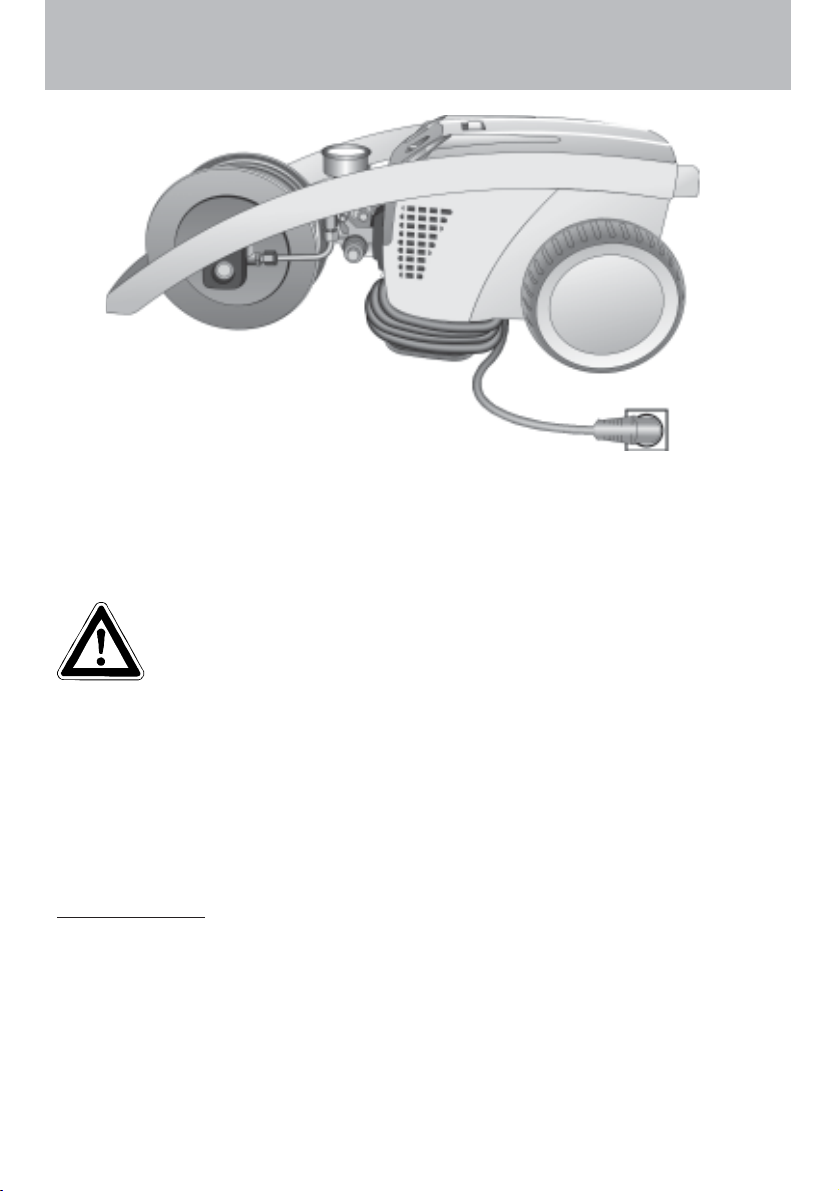
Electrical connection
The machine is supplied with an electrical power cord with plug.
The mains plug must be fitted to a standard grounded socket
with a 30mA residual current operated device. The socket must
be protected with a 16A delay action fuse on the mains side.
11
10 V - 127 V10 V - 127 V
1
10 V - 127 V
11
10 V - 127 V10 V - 127 V
220 V - 240 V220 V - 240 V
220 V - 240 V
220 V - 240 V220 V - 240 V
KRÄNZLE 1150 / 1150 T - 220-240 VKRÄNZLE 1150 / 1150 T - 220-240 V
KRÄNZLE 1150 / 1150 T - 220-240 V
KRÄNZLE 1150 / 1150 T - 220-240 VKRÄNZLE 1150 / 1150 T - 220-240 V
KRÄNZLE 1120 / 1120 T - 110-117 VKRÄNZLE 1120 / 1120 T - 110-117 V
KRÄNZLE 1120 / 1120 T - 110-117 V
KRÄNZLE 1120 / 1120 T - 110-117 VKRÄNZLE 1120 / 1120 T - 110-117 V
KRÄNZLE 1150 / 1150T - 220-240 VKRÄNZLE 1150 / 1150T - 220-240 V
KRÄNZLE 1150 / 1150T - 220-240 V
KRÄNZLE 1150 / 1150T - 220-240 VKRÄNZLE 1150 / 1150T - 220-240 V
When using an extension cable, this must have an earthed lead
which is properly connected to the socket. The conductors in the
extension cable must have a minimum cross section of 1.5 mm².
Plug connections must be of a spray-proof design, and may not
be located on a wet floor.
(with extension cables of more than 10 m - 2.5 mm
olt 50 Hzolt 50 Hz
olt 50 Hz
olt 50 Hzolt 50 Hz
olt 60 Hzolt 60 Hz
olt 60 Hz
olt 60 Hzolt 60 Hz
olt 60 Hzolt 60 Hz
olt 60 Hz
olt 60 Hzolt 60 Hz
2
)
CAUTION !
The use of extension cables which are too long may lead to malfunctions
and start up difficulty.
When using a cable drum, always keep the cable wound as far as possible.
6
Page 7
DescriptionDescription
Description
DescriptionDescription
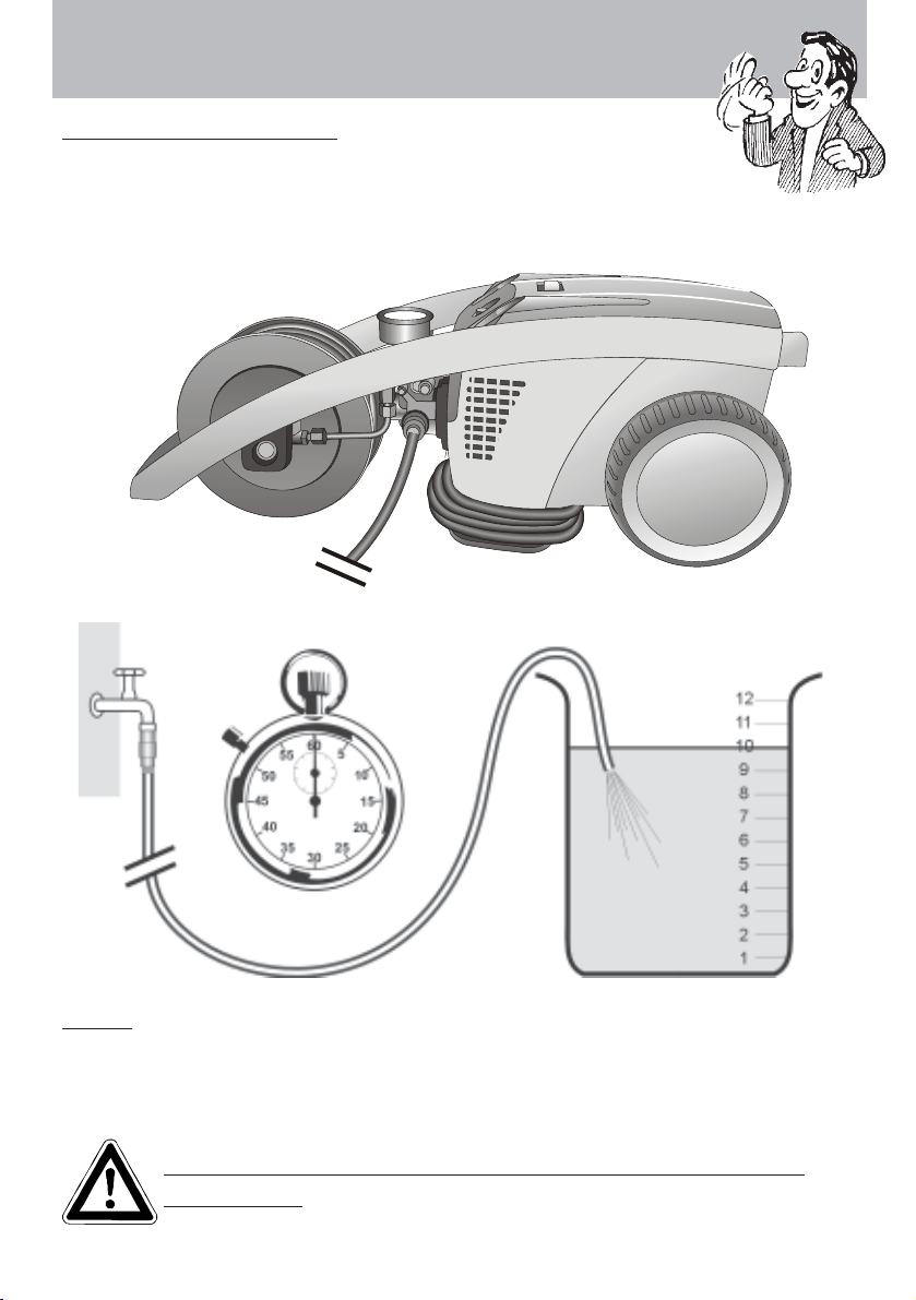
Water connection:
Please check that the high pressure cleaner has available the quantity
of water specified on page 2 (techn. specs.) (Litres per minute) .
3
3
Test:
Allow the water supply hose to run for 1 minute into a bucket.
The received quantity of water must be at least the quantity given on page 2 !!!
Lack of water causes fast wear on seals (no
warranty)
7
Page 8

Description
Brief operating instructions
When operating your high pressure cleanerWhen operating your high pressure cleaner
When operating your high pressure cleaner
When operating your high pressure cleanerWhen operating your high pressure cleaner
pay attention that it is
1.1.
Connect the high pressure hose with spray gun.Connect the high pressure hose with spray gun.
1.
Connect the high pressure hose with spray gun.
1.1.
Connect the high pressure hose with spray gun.Connect the high pressure hose with spray gun.
2.2.
Connect to suitable water supplyConnect to suitable water supply
2.
Connect to suitable water supply
2.2.
Connect to suitable water supplyConnect to suitable water supply
3.3.
Flush the air from the pump (open and close theFlush the air from the pump (open and close the
3.
Flush the air from the pump (open and close the
3.3.
Flush the air from the pump (open and close theFlush the air from the pump (open and close the
spray gun several times)spray gun several times)
spray gun several times)
spray gun several times)spray gun several times)
4.4.
Make the electrical connectionMake the electrical connection
4.
Make the electrical connection
4.4.
Make the electrical connectionMake the electrical connection
5.5.
Switch on the machine with opened spray gun and commenceSwitch on the machine with opened spray gun and commence
5.
Switch on the machine with opened spray gun and commence
5.5.
Switch on the machine with opened spray gun and commenceSwitch on the machine with opened spray gun and commence
cleaning.cleaning.
cleaning.
cleaning.cleaning.
6.6.
After completing the work, completely empty the pump (switchAfter completing the work, completely empty the pump (switch
6.
After completing the work, completely empty the pump (switch
6.6.
After completing the work, completely empty the pump (switchAfter completing the work, completely empty the pump (switch
the motor on for approximately 20 seconds without thethe motor on for approximately 20 seconds without the
the motor on for approximately 20 seconds without the
the motor on for approximately 20 seconds without thethe motor on for approximately 20 seconds without the
suction and spray gun).suction and spray gun).
suction and spray gun).
suction and spray gun).suction and spray gun).
- Only use clean water ! Protect from frost !- Only use clean water ! Protect from frost !
- Only use clean water ! Protect from frost !
- Only use clean water ! Protect from frost !- Only use clean water ! Protect from frost !
CAUTION !
Please pay attention to the regulations of your waterworks company. In
accordance with EN 61 770, the machine may not be directly connected to
the public drinking water supply lines.
A brief connection however is permissible according to DVGW (German
Association for Gas and Water Affairs) if a tube ventilator with check valve
(Kränzle Order-No. 41.016 4) is built into the water supply.
in a horizontal position.
..
.
..
Also indirect connection to the public drinking water supply lines is permissible by way of free emission in accordance with
reservoir with a float valve.
Direct connection to a non-drinking water supply line is permissible.
EN 61 770; e.g. by using a
High pressure hose and spray device
The high pressure hose and spraying device supplied with the machine are
made of high grade material, they are also optimized for the machine and
marked as required by the appropriate regulations.
- Hose length max. 20m.
If replacement parts are required, only such parts that
are authorized by the manufacturer and which bear the
markings required by the appropriate regulations may
be used. The high pressure hose and spray device
must be connected in a pressure-tight manner (no
leak). The high pressure hose may not be driven over,
pulled excessively, or twisted. The hose may under no
circumstances be pulled over sharp edges, since otherwise the guarantee is automatically void.
8
Page 9
Safety notesSafety notes
Safety notes
Safety notesSafety notes
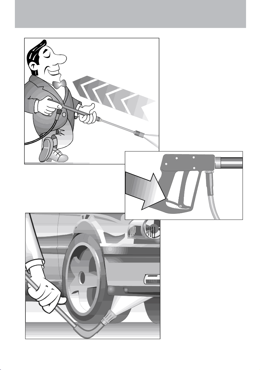
Apply the safety catch onApply the safety catch on
Apply the safety catch on
Apply the safety catch onApply the safety catch on
the spray gun after eachthe spray gun after each
the spray gun after each
the spray gun after eachthe spray gun after each
use, in order to preventuse, in order to prevent
use, in order to prevent
use, in order to preventuse, in order to prevent
unintentional spraying!unintentional spraying!
unintentional spraying!
unintentional spraying!unintentional spraying!
As to the recoil -As to the recoil -
As to the recoil -
As to the recoil -As to the recoil see notice on pagesee notice on page
see notice on page
see notice on pagesee notice on page
2!2!
2!
2!2!
Always aim theAlways aim the
Always aim the
Always aim theAlways aim the
underbody lance.underbody lance.
underbody lance.
underbody lance.underbody lance.
Note when using anNote when using an
Note when using an
Note when using anNote when using an
angled underbodyangled underbody
angled underbody
angled underbodyangled underbody
lance, like for exam-lance, like for exam-
lance, like for exam-
lance, like for exam-lance, like for example lance No. 41.075ple lance No. 41.075
ple lance No. 41.075
ple lance No. 41.075ple lance No. 41.075
1, that there is a1, that there is a
1, that there is a
1, that there is a1, that there is a
certain amount ofcertain amount of
certain amount of
certain amount ofcertain amount of
torque in the recoil.torque in the recoil.
torque in the recoil.
torque in the recoil.torque in the recoil.
(See also notice on(See also notice on
(See also notice on
(See also notice on(See also notice on
page 2)page 2)
page 2)
page 2)page 2)
9
Page 10
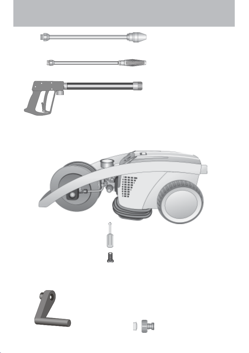
This is what you’ve purchased:This is what you’ve purchased:
This is what you’ve purchased:
This is what you’ve purchased:This is what you’ve purchased:
1. Dirtkiller with nozzle 045
(at 1120 T and 1150 T)
2. Spray lance with
Vario - Jet nozzle
3. Spray gun with
insulated pistol grip
and screw connection
4. KRÄNZLE - High pressure cleaners 1120 T / 1150 T (50/60 HZ)
with hose drum and 15 m high pressure hose with steel reinforcement
5. Crosstip screwdriver
Fixing screw for crank
7. Crank for hose drum
10
6. Operating
instructions
8. Water inlet components
Page 11
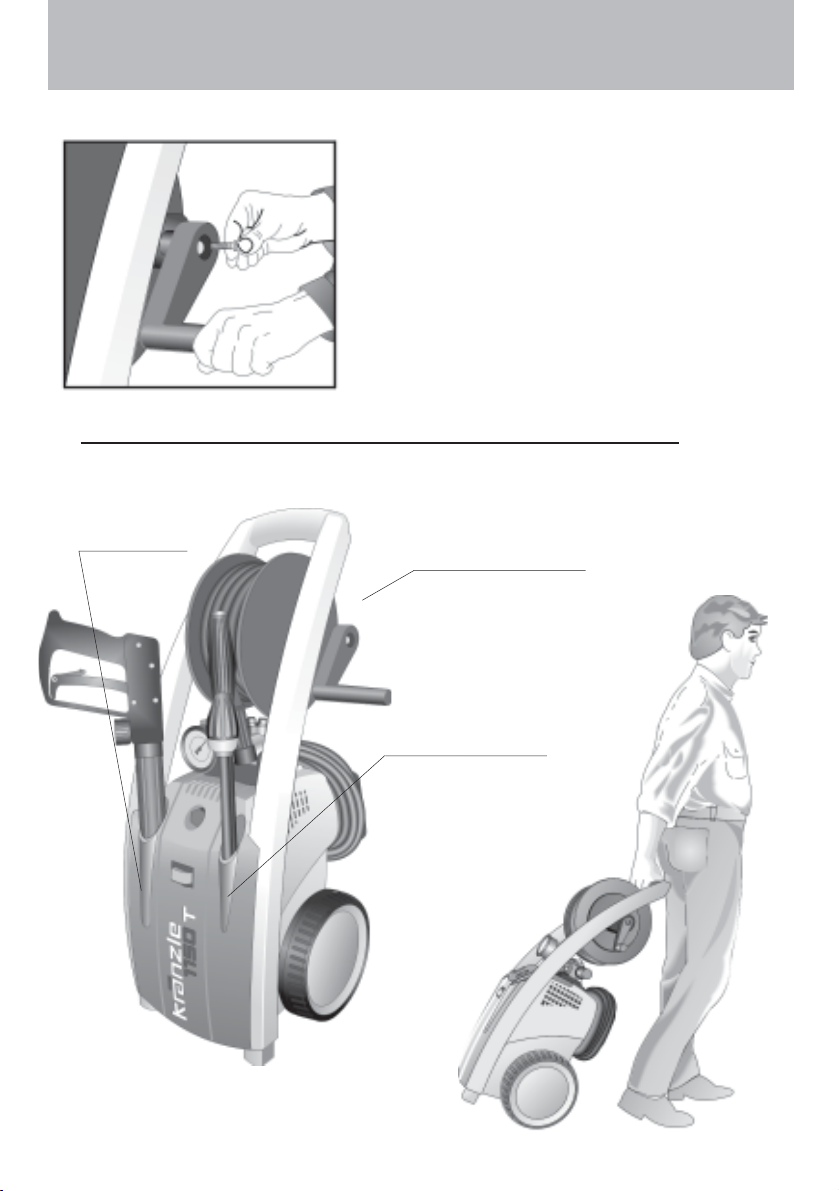
How to assemble and furnish your high pressure cleaner
Put high pressure cleaner into upright
position. Remove the screw from the
brass element. Put the crank on the
hexagon and fasten with the screw.
Receptacle
for gun
Hose drum
with HP-hose
Receptacle
for lances
11
Page 12
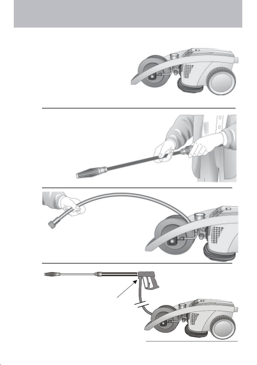
Preparation for use
1. Put high pressure cleaner into
horizontal position!
THE HIGH PRESSURE
CLEANER IS ONLY TO
BE OPERATED IN
HORIZONTAL
POSITION !
2. Connect the high pressure
lance to the spray gun.
12
Unroll hose
without kinks and
connect with handgun and
pump. Max. extension 20m-HP
hose or 2 x 10m with hose
connections.
High pressure hose
connected to machine
and spray gun.
3
3
Page 13

Please make sure
that the filter is clean before
using your high pressure
cleaner.
CAUTION !
When running your high pressure cleaner with hot water of
60
Do not touch the pump without safety gloves!Do not touch the pump without safety gloves!
Do not touch the pump without safety gloves!
Do not touch the pump without safety gloves!Do not touch the pump without safety gloves!
Preparation for usePreparation for use
Preparation for use
Preparation for usePreparation for use
4.4.
The machine can be connected toThe machine can be connected to
4.
The machine can be connected to
4.4.
The machine can be connected toThe machine can be connected to
a pressurised water line witha pressurised water line with
a pressurised water line with
a pressurised water line witha pressurised water line with
60 60
60
60 60
°°
° C raised temperatures occur.
°°
°°
C hot water (see page 2).C hot water (see page 2).
°
C hot water (see page 2).
°°
C hot water (see page 2).C hot water (see page 2).
Ensure that the water supply isEnsure that the water supply is
Ensure that the water supply is
Ensure that the water supply isEnsure that the water supply is
clean when sucking from externalclean when sucking from external
clean when sucking from external
clean when sucking from externalclean when sucking from external
sources. The hose cross sectionsources. The hose cross section
sources. The hose cross section
sources. The hose cross sectionsources. The hose cross section
must be at least 1/2" = 12.7 mmmust be at least 1/2" = 12.7 mm
must be at least 1/2" = 12.7 mm
must be at least 1/2" = 12.7 mmmust be at least 1/2" = 12.7 mm
(free passage). Filter 1 must(free passage). Filter 1 must
(free passage). Filter 1 must
(free passage). Filter 1 must(free passage). Filter 1 must
always be clean.always be clean.
always be clean.
always be clean.always be clean.
5. Maximum induction5. Maximum induction
5. Maximum induction
5. Maximum induction5. Maximum induction
height 1,0 mheight 1,0 m
height 1,0 m
height 1,0 mheight 1,0 m
see technicalsee technical
see technical
see technicalsee technical
data on page 2data on page 2
data on page 2
data on page 2data on page 2
3
3
WW
aterater
W
ater
WW
aterater
13
Page 14

Preparation for usePreparation for use
Preparation for use
Preparation for usePreparation for use
Adjusting the pressure
This is accomplished by turning the
handwheel. The default setting is
maximum pressure.
When using cleansing agents:
Unwind HP-hose completely.
Place chemical filter no. 5 in the
reservoir with the cleansing agent.
Turn on Vario-Jet No. 4 to to enable the
injector to induct the cleansing agent. By
turning back the Vario-Jet nozzle, the supply of
chemical is automatically cut off. Allow the cleansing agent to take effect and then remove with high
pressure spray.
chem. Pmax
Max high pressure hose
length 20m
A mixing ratio of 3-5% is achieved when
the Vario-Jet is fully turned on. pH value
neutral 7-9.
Note that you must always
comply with the instructions
provided by the manufacturer of the cleansing agent
(e.g. instructions concerning
safety clothing) and the water
protection regulations!
4
Turn on Vario-Jet to reach low
pressure !
3
3
5
3
3
To shut down the pump:
1. Switch off the machine.1. Switch off the machine.
1. Switch off the machine.
1. Switch off the machine.1. Switch off the machine.
2. Cut of2. Cut of
2. Cut of
2. Cut of2. Cut of
3. Open the spray gun briefly3. Open the spray gun briefly
3. Open the spray gun briefly
3. Open the spray gun briefly3. Open the spray gun briefly
until the pressure is released. until the pressure is released.
until the pressure is released.
until the pressure is released. until the pressure is released.
4. Apply the safety catch on the spray gun.4. Apply the safety catch on the spray gun.
4. Apply the safety catch on the spray gun.
4. Apply the safety catch on the spray gun.4. Apply the safety catch on the spray gun.
5. Remove the water hose and spray gun.5. Remove the water hose and spray gun.
5. Remove the water hose and spray gun.
5. Remove the water hose and spray gun.5. Remove the water hose and spray gun.
6. Drain the pump: switch on the motor for approx. 20 seconds.6. Drain the pump: switch on the motor for approx. 20 seconds.
6. Drain the pump: switch on the motor for approx. 20 seconds.
6. Drain the pump: switch on the motor for approx. 20 seconds.6. Drain the pump: switch on the motor for approx. 20 seconds.
7. Pull the plug from the socket.7. Pull the plug from the socket.
7. Pull the plug from the socket.
7. Pull the plug from the socket.7. Pull the plug from the socket.
8. Winter: store the pump in rooms above 08. Winter: store the pump in rooms above 0
8. Winter: store the pump in rooms above 0
8. Winter: store the pump in rooms above 08. Winter: store the pump in rooms above 0
9. Clean the water filter9. Clean the water filter
9. Clean the water filter
9. Clean the water filter9. Clean the water filter
14
f the water supplyf the water supply
f the water supply
f the water supplyf the water supply
..
.
..
..
.
..
°°
C.C.
°
C.
°°
C.C.
Page 15

This is prohibited !This is prohibited !
This is prohibited !
This is prohibited !This is prohibited !
Never allow children
to use the high
pressure cleaner !
Never direct the
water jet at the
machine itself !
Never direct the
water jet at a power
socket !
15
Page 16

This is prohibited !
Never direct the
water jet at people
or animals !
Do not damage the
power cord or repair
it incorrectly !
16
Never pull the high
pressure hose if it
has formed kinks or
“nooses”!
Never pull the hose
over sharp edges !
Page 17
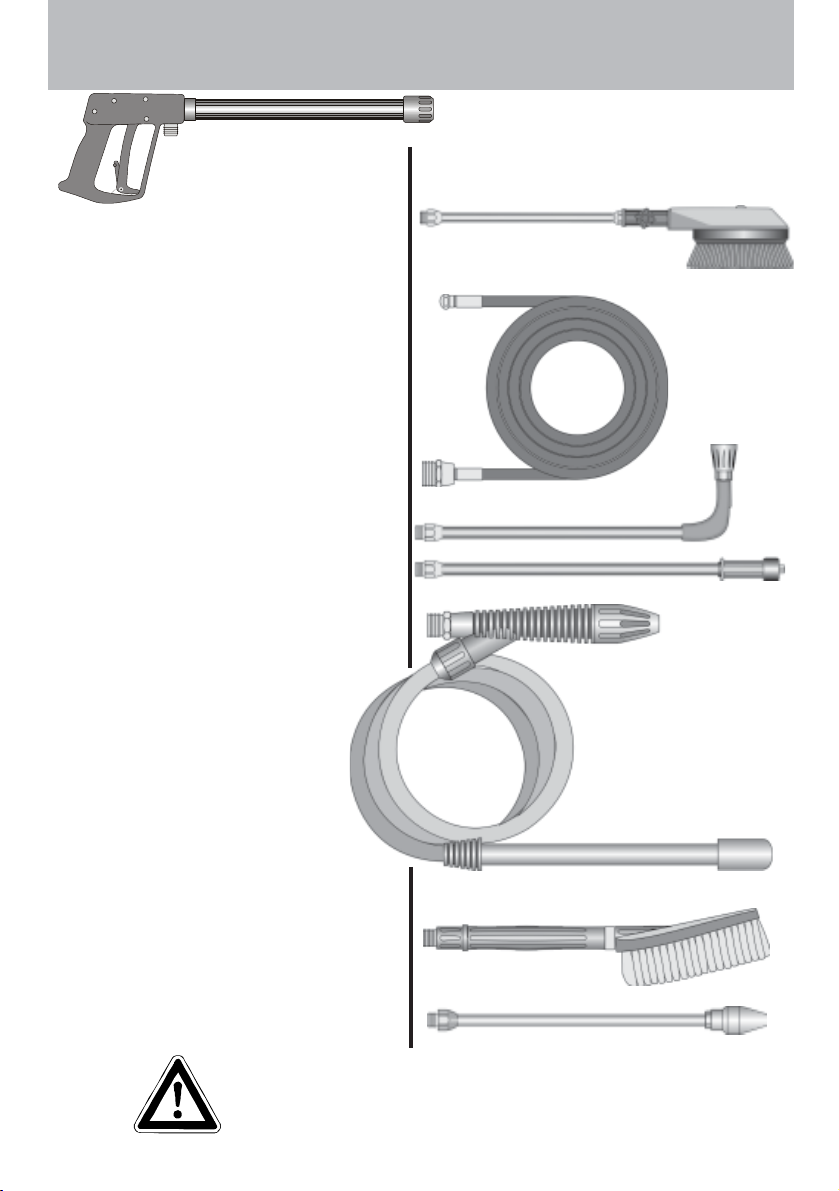
Additional KRÄNZLE-accessories for ...Additional KRÄNZLE-accessories for ...
Additional KRÄNZLE-accessories for ...
Additional KRÄNZLE-accessories for ...Additional KRÄNZLE-accessories for ...
Rotary scrubbing brushRotary scrubbing brush
Rotary scrubbing brush
Rotary scrubbing brushRotary scrubbing brush
Order No. 41.050 1
Drain and pipe cleaning hoseDrain and pipe cleaning hose
Drain and pipe cleaning hose
Drain and pipe cleaning hoseDrain and pipe cleaning hose
10 m - Order No. 41.058 1
15 m - Order No. 41.058
Underbody lance, newUnderbody lance, new
Underbody lance, new
Underbody lance, newUnderbody lance, new
Order No. 41.075 1
SandblasterSandblaster
Sandblaster
SandblasterSandblaster
Order No. 41.068 1
Flat brushFlat brush
Flat brush
Flat brushFlat brush
Order No. 41.073
DirtkillerDirtkiller
Dirtkiller
DirtkillerDirtkiller
Order No. 41.072 5
17
Environmental, refuse disposal and waterEnvironmental, refuse disposal and water
Environmental, refuse disposal and water
Environmental, refuse disposal and waterEnvironmental, refuse disposal and water
protection regulations must be observedprotection regulations must be observed
protection regulations must be observed
protection regulations must be observedprotection regulations must be observed
when using the accessories!when using the accessories!
when using the accessories!
when using the accessories!when using the accessories!
Page 18

... for further combination possibilities... for further combination possibilities
... for further combination possibilities
... for further combination possibilities... for further combination possibilities
Car cleaning, glass, caravan, boat etc.
rotary washing brush with 40 cm extension and ST 30 nipple M 22 x 1,5
Cleaning pipes, channels and drains:
pipe cleaning hose with KN nozzle
and ST 30 nipple M 22 x 1,5
Underbody cleaning of cars, trailers and
equipment: lance 90 cm with high pressure
nozzle and ST 30 nipple M 22 x 1,5.
The lance must be aimed when spraying.
Blasting old paint, rust and facades: sandblasting injector with suction lance, 3 m
PVC hose and ST 30 nipple.
When sandblasting youWhen sandblasting you
When sandblasting you
When sandblasting youWhen sandblasting you
must wear protectionmust wear protection
must wear protection
must wear protectionmust wear protection
clothes! Pay attention toclothes! Pay attention to
clothes! Pay attention to
clothes! Pay attention toclothes! Pay attention to
the instructions of thethe instructions of the
the instructions of the
the instructions of thethe instructions of the
manufacturer of themanufacturer of the
manufacturer of the
manufacturer of themanufacturer of the
abrasive!abrasive!
abrasive!
abrasive!abrasive!
Cleaning cars and all smooth surfaces :
brush with ST 30 nipple.
18
Rotary point sprayer for extreme soiling.
Dirtkiller with 40 cm extension and ST 30
nipple.
Page 19

Small repairs - Do it yourself!Small repairs - Do it yourself!
Small repairs - Do it yourself!
Small repairs - Do it yourself!Small repairs - Do it yourself!
Y ou only get a weak flow of water or no water at all!
The pressure gauge shows a 10% higher pressure than the working pressure.
The injector may
be dirty and you
should first
remove
the hose!
Then straighten a
paper clip ...
Clean the injector
thoroughly from both
sides ...
... release feed
line and injector
with an open ended
spanner ...,
and check that it
is clean.
Now turn on the water and
you should get a powerful
stream of water
... and pull out
the injector!
But if you only
get a weak flow
Reconnect
injector and
feed line.
Reconnect the
hose ...
and you are
ready to continue
your work!
19
Page 20

Small repairs -Small repairs -
Small repairs -
Small repairs -Small repairs -
The nozzle is blocked!
No water but the gauge shows full pressure !No water but the gauge shows full pressure !
No water but the gauge shows full pressure !
No water but the gauge shows full pressure !No water but the gauge shows full pressure !
Rinse the hose through
first.
remove the lance and clean
the nozzle.
Insert pointed object
into the hole and pull
the cap back!
You should now have a
powerful stream of
water,
Straighten a paper
clip and clean the
nozzle.
but if you
only get a few
drops from
the lance
Using the flat spray lance you
only have to clean the front
nozzle.
Check visually whether the
nozzle is clean.
20
Now it works as well
as before.
Page 21

- Do it yourself!- Do it yourself!
- Do it yourself!
- Do it yourself!- Do it yourself!
Nozzle dirty or sticky!
Pressure gauge does not show full pressure.
Water comes out in spurts.
If you do not use the high-pressure cleaner
for some time the valves can stick
When a valve is blocked,
Open the valve
with a socket
wrench...
the gauge
shows little
pressure or
no pressure
at all,
and remove the
valve screw, the
valve and the
o-ring.
The high-pressure
hose vibrates.
or the high
pressure
hose vibrates!
Straighten a
paper clip...
and remove the dirt
from the valve - the
valve inside must
be closed.
Retighten the
valve screw
Replace the rubber o-ring.
...and repeat
on all 6
valves.
Now it works
as well as
before!
21
Page 22

Small repairs - Do it yourself!Small repairs - Do it yourself!
Small repairs - Do it yourself!
Small repairs - Do it yourself!Small repairs - Do it yourself!
Stopping leaks from hose or gunStopping leaks from hose or gun
Stopping leaks from hose or gun
Stopping leaks from hose or gunStopping leaks from hose or gun
After closing the gun the manometer shows full pressure !After closing the gun the manometer shows full pressure !
After closing the gun the manometer shows full pressure !
After closing the gun the manometer shows full pressure !After closing the gun the manometer shows full pressure !
The pressure regulator switches on and off contunuously!The pressure regulator switches on and off contunuously!
The pressure regulator switches on and off contunuously!
The pressure regulator switches on and off contunuously!The pressure regulator switches on and off contunuously!
If the
manometer
shows full
pressure,
Pull out the
power plug!
Press the
trigger to
release the
pressure!!!
First
disconnect
the hose!
Then unscrew the
pump outlet with an
open-jew wrench.
The pressure
regulator
switches on
and off from
pressure
loss!
Clean the return
element or replace
the O-Ring !
Water can emerge at
these 3 points.
Check the seals and
replace the O-Ringe if necessary
or ave the gun checked by the dealer.
Problem
solved already!
Replace the O-Ring
at the lance or at the
HP hose respectively!
22
Reconnect
the hose, gun
and lance!
Page 23

Dirtkiller (special accessory)Dirtkiller (special accessory)
Dirtkiller (special accessory)
Dirtkiller (special accessory)Dirtkiller (special accessory)
No Description Qty. Ord.-No
1 Sprühkörper 1 41.520
2 O-Ring 6,88 x 1,68 1 41.521
3 Düsensitz 1 41.522
4 Düse 045 1 41.523
5 Stabilisator 1 41.524
6 O-Ring 1 40.016 1
7 Sprühstopfen 1 41.526
8 Rohr 400 mm 2x M 12 x 1 1 41.527
9 ST 30-Nippel M 22 x 1,5 / M 12 x 1 ISK 1 13.363
11 Kappe vorn für Schmutzkiller 1 41.528 1
12 Kappe hinten für Schmutzkiller 045 1 41.540 2
Rep.-kit Dirtkiller 045 41.097
consisting of: 1x 2; 3; 4; 5
Dirtkiller 045 compl. with lance 41.072 5
23
Page 24

Gun with lanceGun with lance
Gun with lance
Gun with lanceGun with lance
24
Page 25

KRÄNZLE 1120 - 1150 TKRÄNZLE 1120 - 1150 T
KRÄNZLE 1120 - 1150 T
KRÄNZLE 1120 - 1150 TKRÄNZLE 1120 - 1150 T
Gun with lance
incl. Pos. 3, 4, 21
.
5 Rohranschlußteil R1/4" 1 12.125
No Description Qty. Ord.-No
Spare parts list KRÄNZLE 1120/1120 T; 1150/1150 T
6 Scheibe 5,3 DIN9021 1 50.152
7 Abzug-Hebel kpl. 1 12.144 1
bds. R 1/4" AG
15 Rohr kunststoffumspritzt 1 15.004 2
16 Überwurfmutter ST 30 M22 x 1,5 IG 1 13.276 1
17 Außen-Sechskant-Nippel R 1/4" IG 1 13.277 1
18 O-Ring 9,3 x 2,4 1 13.273
19 ST 30-Nippel M 22 x 1,5 1 13.363
20 Rohr 400 lang, bds. M12 x 1 1 15.002
21 Aluminium Dichtring 6 13.275 1
30 Klemmstück 1 41.155 2
31 Halterung für Klemmstück 1 41.155 4
32 Kunstoffhülle 1 41.155 1
Pos: 3, 4, 5, 8, 9, 12, 15, 16; 21
33 Vario-Jet 045 1 41.155 6
A Rep.-Kit 12.158
Midi-Pistole kpl. 12.160
B Griff komplett 12.164
Lanze kpl. mit Vario-Jet 41.156
25
Page 26

Complete assemblyComplete assembly
Complete assembly
Complete assemblyComplete assembly
26
Page 27

KRÄNZLE 1120 - 1150 TKRÄNZLE 1120 - 1150 T
(
KRÄNZLE 1120 - 1150 T
KRÄNZLE 1120 - 1150 TKRÄNZLE 1120 - 1150 T
Spare parts list KRÄNZLE 1120 - 1150T
Complete assembly
No Description Qty. Ord.-No
1.1 Motor-Pumpe K1150 ohne Schaltkasten 1 44.542
1.2 Motor-Pumpe K1150 mit Schaltkasten 1 44.542 1
1.3 Motor-Pumpe K1150T ohne Schaltkasten 1 44.543
1.4 Motor-Pumpe K1150T mit Schaltkasten 1 44.543 1
2 Fahrgestell 1 44.502
3 Frontplatte " K 1150 " 1 44.503 1
3.1 Frontplatte " K 1150 T " 1 44.503
4 Köcher groß 1 44.506
5 Köcher klein 1 44.507
6 Knickschutz 1 44.509
7 Rad 2 44.538
8 Radkappe 2 45.200 8
9 Kabelhalteplatte 1 44.505
10 Achse 2 44.504
11 Netzanschlußkabel 1 41.092
12 Chemikaliensaugschlauch mit Filter 1 15.038
13 Versteifungsplatte 1 44.511
15 Kunststoffsenkschraube 5,0 x 20 2 45.421 1
16 O-Ring 9,3 x 2,4 2 13.273
17 Kunststoffschraube 5,0 x 20 20 43.018
18 Auflagepuffer 2 44.510
19 Kunststoffschraube 5,0 x 30 2 41.412
20 Scheibe 40 x 6 x 1,5 (Stahl) 2 45.216 7
21 Unterlegscheibe 8,4 4 50.186
22 Innensechskantschraube M 8x 30 4 41.036 1
23 Kunststoffschraube 4,0 x 16 2 43.417
24 Kunststoffschraube 5,0 x 50 2 41.411
25 Kunststoffschraube 5,0 x 70 2 44.519
26 Kunststoffschraube 3,5 x 14 2 44.525
27 Anschlußleitung Schlauchtrommel 1 44.520
28 Midi-Pistole 1 12.160
29 Vario-Jet 045 kpl. mit Lanze 1 41.156
30 Schmutzkiller 1 41.072 5
31 Kabelklemme 1 43.431
32 Schraube 3.5 x 16 2 44.161
33 Griffabdeckung 1 44.535
34 Gummipuffer links+rechts 1 44.536
35 Rad kpl.
7, 8, 10, 15, 20) 2 44.538 2
27
Page 28

Motor
28
Page 29

KRÄNZLE 1120 - 1150 TKRÄNZLE 1120 - 1150 T
KRÄNZLE 1120 - 1150 T
KRÄNZLE 1120 - 1150 TKRÄNZLE 1120 - 1150 T
Spare parts list KRÄNZLE 1120 - 1150 T
Motor
No Description Qty. Ord.-No
1 Ölgehäuse 1 44.501
2 Motorgehäuse mit Stator 230 V / 50 Hz 1 23.002
2.1 Motorgehäuse mit Stator 110 V / 60 Hz 1 23.002 2
2.2 Motorgehäuse mit Stator 230 V / 60 Hz 1 23.002 3
3 Motorwelle mit Rotor 230 V / 50 Hz 1 43.024
3.1 Motorwelle mit Rotor 110 V / 60 Hz 1 43.104
3.2 Motorwelle mit Rotor 230 V / 60 Hz 1 43.629
4 Paßfeder 6 x 6 x 20 1 41.483 1
5 Motor-Lager B-Seite Z-Lager 1 43.025
6 Motor-Lager A-Seite Schulterl. 1 43.026
8 Öldichtung 25 x 35 x 7 1 41.024
9 Lüfterrad 1 43.028
10 Lüfterhaube 1 41.497
11 Flachdichtung 1 44.513
12 Lüsterklemme 3-pol. 1 43.031 2
13 Schaltkasten 1 44.508
14 Schalter mit 13,5 A-Überstromauslöser 1 41.110 2
15 Klemmrahmen mit Schalterabdichtung 1 43.453
16 Kabelverschraubung PG 11 1 41.419
17 Gegenmutter PG 11 1 44.521
18 Kondensator 40 µF 1 43.035
K 1150 / K 1150 T ( 230V ; 50/60Hz )
18.1 Kondensator 80µF für 1 43.505
K 1120 / K 1120 T ( 110V ; 50/60Hz )
19 Netzkabel für 230V / 50/60Hz 1 41.092
19.1 Netzkabel für 110V / 60Hz 1 43.512
20 Blechschraube 3,5 x 9,5 2 41.088
21 Blechschraube 2,9 x 16 1 43.036
22 Innensechskantschr. M 5 x 12 4 40.134
23 Innensechskantschr. M 5 x 30 4 42.130
24 Erdungsschraube kpl. 1 43.038
25 Deckel für Schaltkasten 1 44.512
26 Dichtung für Deckel 1 44.522
27 Kunststoffschraube 5,0 x 25 4 41.414
28 Blechschraube 3,9 x 9,5 3 41.636
29 Toleranzhülse 1 43.063 1
Motor compl. w. oil housing and 1 44.530
fan wheel without elect. for 230V / 50 Hz
Motor compl. w. oil housing and 1 44.530 1
fan wheel without elect. for 110V / 60 Hz
Motor compl. w. oil housing and 1 44.530 2
fan wheel without elect. for 230V / 60 Hz
29
Page 30

TT
ransmissionransmission
T
ransmission
TT
ransmissionransmission
30
Page 31

KRÄNZLE 1120 - 1150 TKRÄNZLE 1120 - 1150 T
KRÄNZLE 1120 - 1150 T
KRÄNZLE 1120 - 1150 TKRÄNZLE 1120 - 1150 T
Transmission
Spare parts list KRÄNZLE 1120 - 1150 T
No Description Qty. Ord.-No
1 Gehäuseplatte 1 43.003
2 Öldichtung 14 x 24 x 7 3 41.631
3 O-Ring 83 x 2 1 43.039
4 Plungerfeder 3 43.040
5 Federdruckscheibe 14 mm 3 43.041
6 Plunger 14 mm 3 43.005
7 Sprengring 14 mm 3 41.635
Taumelscheibe 9,25° für K1150 230V/ 50Hz 1 41.028-9,25
Taumelscheibe 9,25° für K1150 T 230V/ 50Hz 1 41.028-9,25
Taumelscheibe 8,0° für K1150 230V/ 60Hz 1 41.028-8,0
8 Taumelscheibe 12,0° für K1120 1 41.028-12,0
please specifiy angle when ordering
10 Axial-Rillenkugellager 3-teilig 1 43.486
12 Innensechskantschraube M 8 x 25 4 40.053
13 Verschlußschraube M 18 x 1,5 1 41.011
14 O-Ring 12 x 2 2 15.005 1
15 Ölschauglas 1 42.018 1
16 Ölverschlußschraube rot 1 43.437
17 Dichtung Öldeckel 1 44.501 1
18 Deckel Ölgehäuse 1 44.501 2
19 Innensechskantschraube M 5 x 12 4 41.019 4
31
Page 32

VV
alve housing K 1120 T - K 1150 Talve housing K 1120 T - K 1150 T
V
alve housing K 1120 T - K 1150 T
VV
alve housing K 1120 T - K 1150 Talve housing K 1120 T - K 1150 T
32
Page 33

KRÄNZLE 1120 T - 1150 TKRÄNZLE 1120 T - 1150 T
KRÄNZLE 1120 T - 1150 T
KRÄNZLE 1120 T - 1150 TKRÄNZLE 1120 T - 1150 T
No Description Qty. Ord.-No
31 Leckagering 3 43.053
33 Zwischenring mit Abstützung 3 43.055
34 Rückschlagfeder 1 14.120 1
35 Verschlußstopfen für
32 Manschette 14 x 20 x 4/2 3 43.054
Kugelrücks.v. 1 44.524
36 Ermetowinkel R1/4"x8 1 40.179
42 Innensechskantschr. M 8 x 25 2 40.053
43 Innensechskantschr. M 8 x 40 2 43.059
44 Dichtring Kupfer 1 14.149
45 Sauganschluß 1 41.016
46 Wasserfilter 1 41.046 1
48 Gummi Dichtring 1 41.047 1
49 Steckkupplung 1 41.047 2
50 O-Ring 1 41.047 3
Rep.-kit valves 41.648
6x Pos. 4, 12x Pos. 7
Rep.-kit sleeves 43.060
Valve housing
Spare parts list KRÄNZLE 1120 T - 1150 T
18 Kolbenführung 6 mm 1 14.130 1
No Description Qty. Ord.-No
1 Ventilgehäuse 1 44.523
9 Edelstahlsitz 2 14.118
10 Sicherungsring 2 13.147
11 Edelstahlkugel 8,5 mm 2 13.148
12 Edelstahlfeder 1 14.119
13 Verschlußschraube 1 14.113
14 Steuerkolben 6 mm für AZ 1 43.044
6 Dichtstopfen M 10 x 1 1 43.043
7 O-Ring 12 x 2 15 15.005 1
5 Dichtstopfen M 8 x 1 1 13.158
8 O-Ring 11 x 1,5 2 12.256
2 Ventilstopfen 5 41.011
3 Ventilstopfen mit R1/4" IG 1 41.011 1
4 Ventile (rot) 6 41.612
15 Parbaks für Kolben 14 mm 1 14.123 1
16 Parbaks für Spindel 6 mm 1 14.123 2
17 MS-Scheibe 1 43.045
19 Mutter M 6 2 14.127 1
3x Pos. 28; 3x Pos. 29; 3x Pos. 30, 3x Pos. 32
Valve housing compl. 44.531
Pos. 1-25; Pos. 27-43
Guide piston with seals 44.532
Pos. 14; Pos. 15
Guide piston with handwheel 44.532 1
Pos. 7; Pos. 14-25
20 Feder schwarz für AZ-Pumpe 1 43.046
21 Federdruckscheibe 1 43.047
22 Kugellager 1 43.048
23 Handrad M 6 für AZ-Pumpe 1 43.049
24 Mutter M 6 mit SW 8 1 43.010
25 Kappe für Handrad AZ-Pumpe 1 43.050
26 Manometer 1 15.039
27 Stützring 3 43.091
28 Gewebemanschette 14x24x5 3 41.613 1
29 Backring 14 x 24 3 41.614
30 O-Ring 26 x 2 3 43.052
33
Page 34

VV
alve housing K 1120 - K 1150alve housing K 1120 - K 1150
V
alve housing K 1120 - K 1150
VV
alve housing K 1120 - K 1150alve housing K 1120 - K 1150
34
Page 35

KRÄNZLE 1120 - 1150KRÄNZLE 1120 - 1150
g
KRÄNZLE 1120 - 1150
KRÄNZLE 1120 - 1150KRÄNZLE 1120 - 1150
43.053
Rep.-kit valves 41.64
6x Pos. 4, 12x Pos. 7
Rep.-kit sleeves 43.060
incl. 7, 2x37, 2x38, 39, 40, 41
3x Pos. 28; 3x Pos. 29; 3x Pos. 30, 3x Pos. 32
Valve housing compl. 44.533
Pos. 1-25; Pos. 27-43
Guide piston with seals 44.532
Pos. 14; Pos. 15
Guide piston with handwheel 44.532 1
Pos. 7; Pos. 14-25
No Description Qty. Ord.-No
31 Leckagering 3
33 Zwischenring mit Abstützung 3 43.055
32 Manschette 14 x 20 x 4/2 3 43.054
34 Rückschlagfeder 1 14.120 1
35 Ausgangsst. Inj. ST30 M22x1,5 1 44.544
36 Verschlusstopfen 1/4“ 1 13.181
37 Verschlussschraube M10x1 2 13.385
38 O-Ring 6x1,5 2 13.386
39 Saugzapfen Schlauchanschluss 1 13.236
40 Edelstahlkugel 5,5 mm 1 13.238
41 Edelstahlfeder 1 13.239
42 Innensechskantschr. M 8 x 25 2 40.053
43 Innensechskantschr. M 8 x 40 2 43.059
44 Dichtring Kupfer 1 14.149
45 Sauganschluss 1 41.016
46 Wasserfilter 1 41.046 1
48 Gummi Dichtring 1 41.047 1
Valve housing
Spare parts list KRÄNZLE 1120 - 1150
No Description Qty. Ord.-No
1 Ventilgehäuse 1 44.523
2 Ventilstopfen 5 41.011
3 Ventilstopfen mit R1/4" IG 1 41.011 1
4 Ventile (rot) 6 41.612
5 Dichtstopfen M 8 x 1 1 13.158
6 Dichtstopfen M 10 x 1 1 43.043
7 O-Ring 12 x 2 15 15.005 1
8 O-Ring 11 x 1,5 2 12.256
9 Edelstahlsitz 2 14.118
10 Sicherungsring 2 13.147
11 Edelstahlkugel 8,5 mm 2 13.148
12 Edelstahlfeder 1 14.119
13 Verschlußschraube 1 14.113
14 Steuerkolben 6 mm für AZ 1 43.044
15 Parbaks für Kolben 14 mm 1 14.123 1
16 Parbaks für Spindel 6 mm 1 14.123 2
17 MS-Scheibe 1 43.045
18 Kolbenführung 6 mm 1 14.130 1
19 Mutter M 6 2 14.127 1
49 Steckkupplung 1 41.047 2
50 O-Ring 1 41.047 3
51 Aluminium-Dichtring 2 13.275
20 Feder schwarz für AZ-Pumpe 1 43.046
21 Federdruckscheibe 1 43.047
22 Kugellager 1 43.048
23 Handrad M 6 für AZ-Pumpe 1 43.049
24 Mutter M 6 mit SW 8 1 43.010
25 Kappe für Handrad AZ-Pumpe 1 43.050
26 Manometer 1 15.039
27 Stützring 3 43.091
28 Gewebemanschette 14x24x5 3 41.613 1
29 Backring 14 x 24 3 41.614
26 x 2 3 43. 052
30 O-Rin
35
Page 36

Hose drumHose drum
Hose drum
Hose drumHose drum
36
Page 37

KRÄNZLE 1120 T - 1150 TKRÄNZLE 1120 T - 1150 T
KRÄNZLE 1120 T - 1150 T
KRÄNZLE 1120 T - 1150 TKRÄNZLE 1120 T - 1150 T
Hose drum
Spare parts list KRÄNZLE 1120 T - 1150 T
No Description Qty. Ord.-No
1 Schale groß 1 40.160
2 Schale klein 1 40.161
3 Knickschutz 1 40.162
4 Antriebswelle 1 44.517
5 Kurbel 1 40.165
6 Lagerklotz links 1 44.515
7 Lagerklotz rechts 1 44.516
8 Drehgelenk 1 40.167
9 Achse mit Wasserführung 1 44.518
10 Eingangsinjektror 1 40.169
11 HD-Schlauch NW 6 15 m 1 40.170
12 Schraube M 6 x 16 1 40.171 1
13 Schraube M 5 x 10 1 43.021
14 Anschlußrohr Ermeto Edelstahl 1 44.520
15 Parbaks 16 mm 2 13.159
16 O-Ring 10 x 2 1 43.068
17 Sicherungsring 16 mm 1 40.182
18 Scheibe MS 16 x 24 x 2 1 40.181
19 O-Ring 6,68 x 1,78 1 40.585
20 Sicherungsring 20 mm 1 40.172
21 Kunststoffschraube 5,0 x 20 4 43.018
22 Zahnscheibe 6,4 1 40.183
23 Scheibe DIN9021 6,4 1 50.174
25 Saugzapfen Schlauchanschluß 1 13.236
26 Edelstahlkugel 5,5 mm 1 13.238
27 Edelstahlfeder 1 13.239
28 Chemikaliensaugschlauch mit Filter 1 15.038
29 O-Ring 6 x 0,8 2 40.177
37
Page 38

Wiring diagramWiring diagram
Wiring diagram
Wiring diagramWiring diagram
Wiring diagram for KRÄNZLE K 1120 - K1150 T
braun = brown
C : 40µF ( 80 µF bei 110V / 60 Hz )
Terminal strip
Weber-Unimat WT 22 - 551
13,5A excess current release
Motor-Stator
blau = blue
schw = black
rt = red
ge = yellow
gn = green
ws = white
38
Page 39

General rulesGeneral rules
General rules
General rulesGeneral rules
Inspections
The machine must be inspected according to the “Guidelines for Liquid Spray
Devices” at least once every 12 months by a qualified person, to ensure that
continued safe operation is guarateed. The results of the inspection are to be
recorded in writing. This may be done in any form.
Accident prevention
The machine is designed for accidents to be impossible if used correctly.
The operator is to be notified of the risk of injury from hot machine parts and the
high pressure water jet. The “Guidelines for Liquid Spray Devices” must be complied with. (see page 14 and 15)
Oil change:
Check the oil level at the oil sight glass prior to each use.
(Ensure horizontal position!) The oil level should be at the middle of
the sight glass. With high atmospheric humidity and temperature
fluctuation there may be condensation (oil has a greyish colour);
Then the oil must be changed.
First oil change after approx 50 hours of operation. Thereafter, no more oil change
is required for the lifetime of the equipment. If it becomes necessary during repairs,
or because the oil has a greyish colour to perform an oil change, then the oil sight
glass should be opened and the oil emptied into a container. The oil must be caught
in a container and disposed of in a responsible, legal manner.
New oil: 0.25 l - Motor oil: W 15/40
Oil leak
In the event of an oil leak contact customer service (dealer) immediately. (damage
to environment or transmission)
39
 Loading...