

Nacecare TTV 678-300T, TTV 678, TTV 300T Owner's Instructions Manual
Owner Instructions
Original Instructions
Warning! Read instructions before using the machine
TTV 678-300T
Ride-on Scrubber Dryer
Operator Instruction Manual

2
Index
Machine overview
Control panel overview
Safety Precautions
Rating label / Personal Protective Equipment / Recycling
Before continuing, please refer to Quick Set Up Guide on Page 7
!
!
Quick set-up guide
Machine set-up
Fitting the side pod skirts
Fitting the oor-tool
Fitting the brushes
Setting the width
Filling the clean-water tank
Chemical dosing system
Pre-cleaning advice
Machine Operation
Lowering the brush-deck
Lowering the oor-tool
Adjusting the seat
Setting the cleaning controls
Setting the operator pre-set buttons
Waste tank warning light
Brush pressure / load adjustment
Emergency stop button and horn
Machine usage advice
Breakaway oor-tool feature
Off-aisle cleaning kit ( optional )
Machine Cleaning
Tanks and Filters
Floor-tool
Machine Charging
Motor brake disengage lever / Towing / Free-wheel function
Battery care / Trip sequences / Trouble shooting / recommended spare parts
Warranty
Wiring Diagrams
Specications
Declaration document
Quality assurance certicate and serial number
Page 2
Page 3
Page 4
Page 5
Page 6
Page 7
Page 8
Page 8
Page 9
Page 10
Page 10
Page 11
Page 11
Page 12
Page 12
Page 13
Page 13
Page 14
Page 14
Page 14
Page 15
Page 15
Page 16
Page 16
Page 17
Page 18
Page 19
Page 20
Page 21 to 25
Page 26
Page 28 to 29
Page 30
Page 31
Back Cover
3
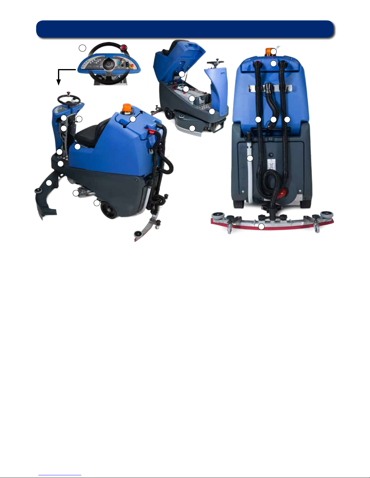
1. Operator control panel ( see page 4 )
2. Brush load-adjuster knob
3. Brush deck-release lever
4. Brush deck-foot pedal
5. Clean-water tank ll point
6. Side pod and skirt
7. Brush deck motors x3
8. Brush deck cover adjustment / width lever
9. Floor-tool raise / lower lever
10. Seat adjustment lever
11. Separator release catches
12. 40 Amp battery fuses x3
13. Gel batteries (606167)
14. Chemical dosing tank (5 litre )
15. Accelerator pedal
16. Clean-water tank emptying hose
17. Semi parabolic oor-tool
18. Vacuum hose
19. Waste water emptying hose
20. Floor-tool vacuum hose
21. Air separator assembly
22. Pedestrian warning light
Machine Overview
1
3
4
5
6
7
8
9
10
12
13
14
15
16
17
18 19 20
21
22
6
11
2
4
For full easy to follow
Instructions on
control panel set up and use,
see machine operation
page 14.
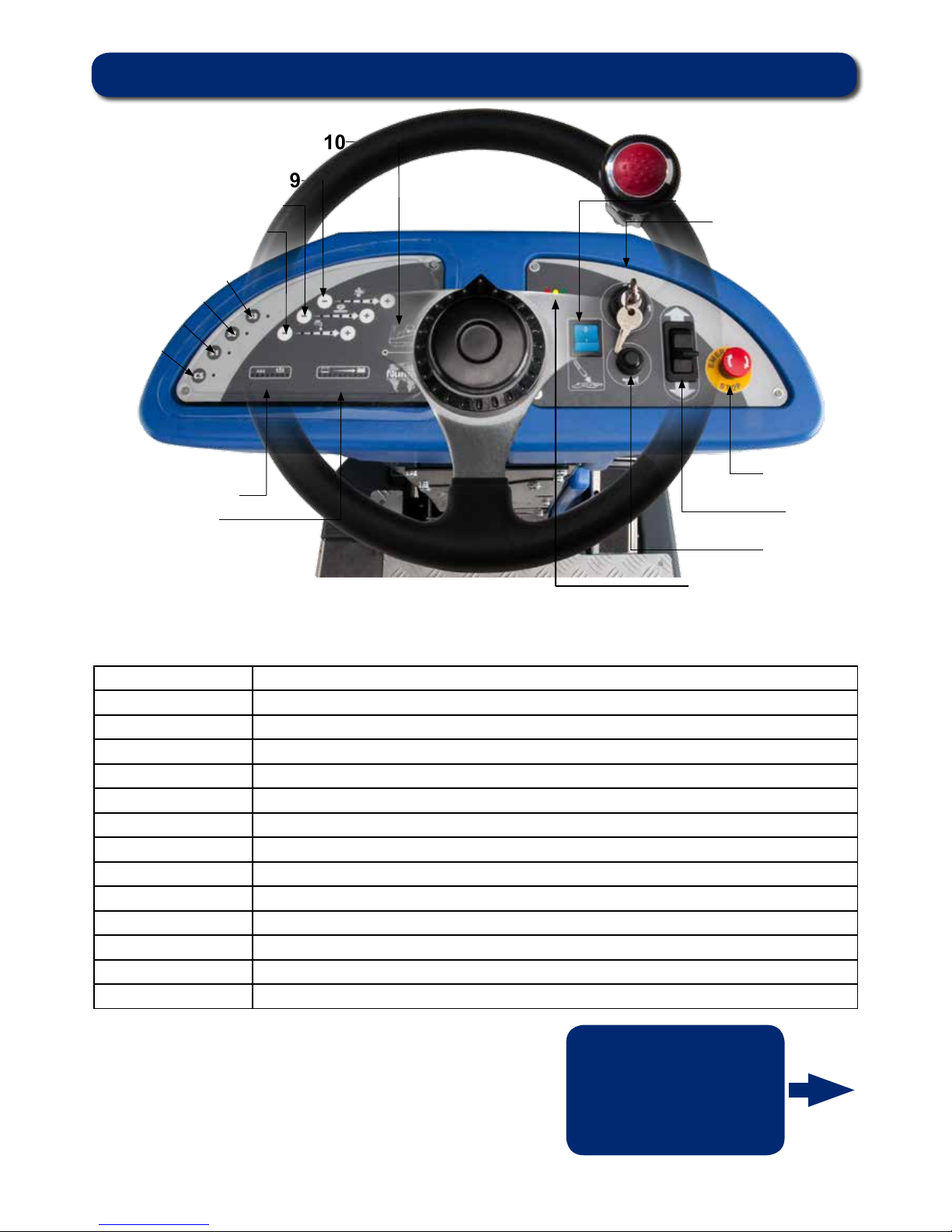
Control Panel Overview
9
10
1
2
3
4
5
6
7
8
11
12
13
14
15
16
1 Battery charge level indicator
2 Brush pressure / Load indicator
3 Clean speed button
4/5/6 Operator pre-set buttons
7 Water ow rate indicator
8 Brush speed indicator
9 Chemical mix indicator
10 Waste water ‘Full’ indicator
11 Off aisle vacuum button
12 Main control On / Off key
13 Emergency stop button
14 Forward / Reverse switch
15 Horn
16 Charger status light
5
Caution Floorsign
Charging Leads: Ho5VV-F x 1mm2 x 3 Core
Motor Wheel & modied brake lead assmenbly (321450)
PG Controller (208169)
Battery Charger (230V )
(115V )
Scrubber dryer accessories and packaging should be sorted for environmentally-friendly
recycling.
Only for EU countries.
Do not dispose of scrubber dryer into household waste.
According to the European directive 2002/96/EC
on Waste Electrical Electronic Equipment (WEEE) and its incorporation into national law.
Scrubber dryers that are no longer suitable for use must be separated, collected and sent for
recovery in an environmentally-friendly manner.
Caution Floorsign
NOTE:
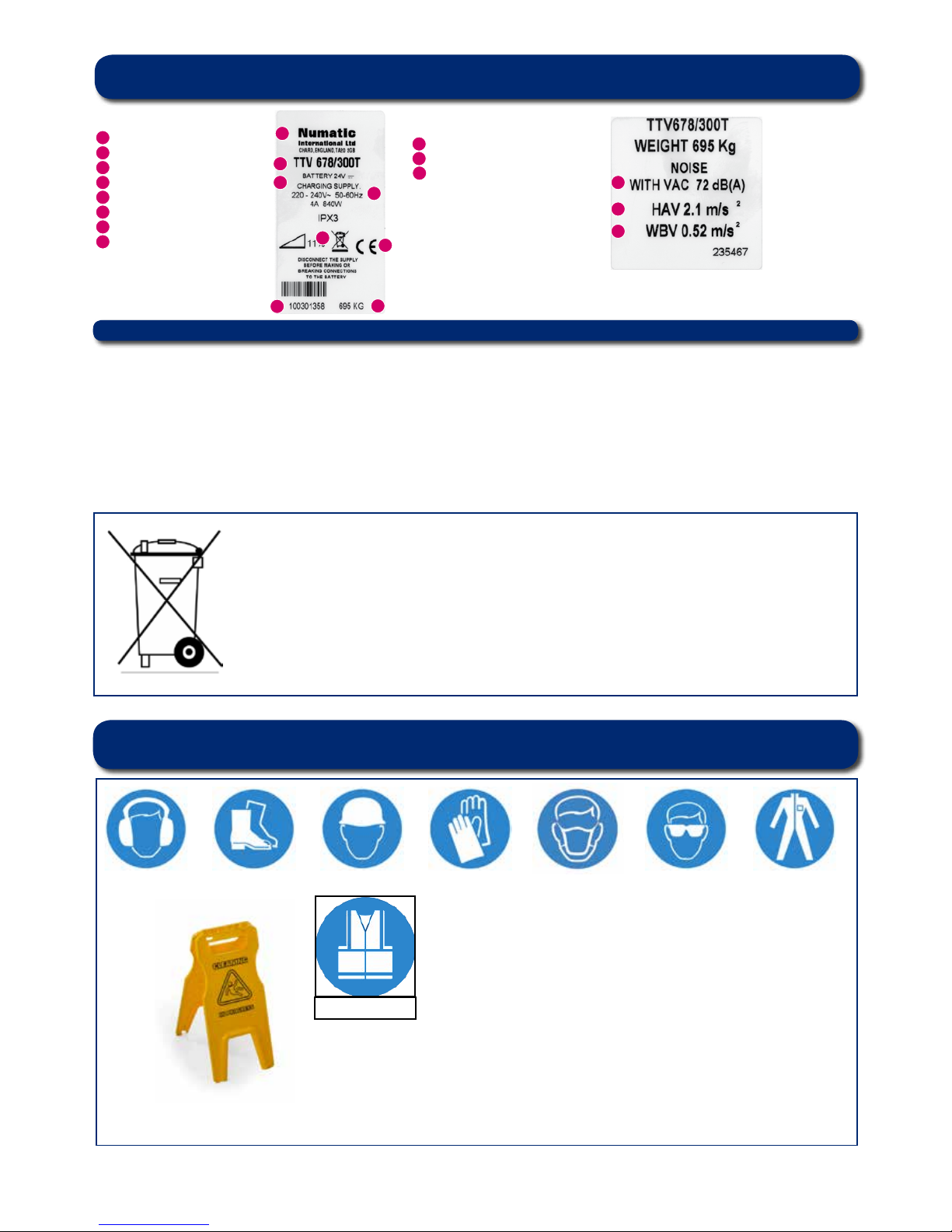
A risk assessment should be conducted
to determine which PPE should be worn.
Ear Protection Safety Footwear Safety Hat Safety Gloves Face Mask Eye Protection Protective Clothing
Hi Viz Jacket
Rating label / Personal Protective Equipment / Recycling
1
2
3
4
5
6
7
8
Rating Label
Company Name & Address
Machine Description
Voltage Frequency
Power rating
WEEE Logo
CE Mark
Machine yr/wk Serial number
Weight (ready to use)
1
2
3
4
5
6
7
8
9
9
Noise level
Hand arm vibration
Whole body vibration
10
11
11
10
Safety Critical Components
PPE
(Personal Protective Equipment) that maybe required for certain operations.

6
Safety Precautions
Caution
Read the instruction manual before using the appliance.
The TTV is a class 1 product when tted with an AC supply lead, but a class 3 product during normal use.
Note
This product meets the requirements of CSA / CAN 60335-22.72 sub clause 20.1
This machine is also suitable for commercial use, for example in hotels, schools, hospitals, factories, shops and ofces for other than normal
housekeeping purposes.
Never attempt to ll the machine’ s water tanks whilst it is charging.
Machines left unattended shall be secured against unintentional movement.
Care should be taken in the choice of chemicals, detergents and other liquids. Consult your supplier.
Do’s and Dont’s
DO ensure only competent persons unpack/assemble the machine.
DO keep your machine clean.
DO keep your brushes in good condition.
DO replace any worn or damaged parts immediately.
DO regularly examine the charger lead for damage, such as cracking or ageing. If damage is found, replace the lead before further use.
DO only replace the charger lead with the correct Numatic approved replacement part.
DO ensure that the work area is clear of obstructions and / or people.
DO ensure that the working area is well illuminated.
DO pre-sweep the area to be cleaned.
DON’T use steam cleaners or pressure washers to clean the machine or use in the rain.
DON’T Don’t attempt machine maintenance or cleaning unless the power plug has been removed from the supply outlet,
if the machine is in charge mode or remove the key if in normal use.
DON’T allow any inexperienced repairs. Contact your nearest service centre.
DON’T strain charger lead or try to unplug by pulling on charger lead.
DON’T leave the brush deck in the lowered position when not in use.
DON’T expect the machine to provide trouble-free, reliable operation unless maintained correctly.
DON’T run the machine over any power cables during operation.
Warning
This machine is not suitable for picking-up hazardous dust.
Do not use on surfaces having a gradient exceeding that marked on the appliance.
As with all electrical equipment care and attention must be exercised at all times during its use, in addition to ensuring that routine and
preventative maintenance is carried out periodically in order to ensure its safe operation. Failure to carry out maintenance as necessary, including
the replacement of parts to the correct standard could render this equipment unsafe and the manufacturer can accept no responsibility or liability in
this respect.
When ordering spare parts always quote the Model Number / Serial Number specied on the Rating Plate.
This machine is for indoor use.
The machine is not to be used or stored outdoors or in wet conditions.
Don’t allow the machine to be used by inexperienced or unauthorised operators or without appropriate training.
Only use brushes provided with the appliance or those specied in the instruction manual. The use of other brushes may impair safety. A full range
of brushes and accessories are available for this product. Only use brushes or pads which are suitable for the correct operation of the machine for
the specic task being performed.
It is essential that this equipment is correctly assembled and operated in accordance with current safety regulations. When using the equipment
always ensure that all necessary precautions are taken to guarantee the safety of the operator and any other persons who may be affected. Wear
non-slip footwear when Scrubbing. Use a respiratory mask in dusty environments.
The machine, while charging, must be positioned so that the mains plug is easily accessible.
Remove the key from the ignition when cleaning and carrying out routine maintenance. When replacing major components the ignition key and
battery fuses MUST be removed.
When detergents or other liquids are used, read the manufacturer’s instructions.
If this product does not have a factory installed Numatic battery charger then it is the responsibility of the owner and user of the product to ensure
that the charging system and battery combination are compatible, t for purpose and safe to use.
Precautions when working with batteries
1. Always wear protective clothing e.g. face visor, gloves and overalls when working with batteries.
2. Whenever possible always use a properly designated and well-ventilated area for charging. Do not smoke or bring naked ames into the
charging area.
3. Remove any metallic items from hands, wrists and neck i.e. rings, chains etc. before working on a battery.
4. Never rest tools or metallic objects on top of the battery.
5. When charging is complete disconnect from the mains supply.
6. The machine must be disconnected from the supply when removing the battery.
7. To remove the batteries:- Disconnect machine from the mains supply (if charging), raise waste water tank and ensure batteries are isolated by
removing fuses. Disconnect hoses from separator and tanks, Undo battery terminals and remove batteries.
8. Only use genuine Numatic replacement batteries.
9. Do not allow the batteries to become fully discharged, it may not be possible to recharge them.
10. Do not allow one battery to be discharged separately to the other.
11. Do not mix batteries from different machines.
12. The batteries tted to this product are Valve Regulated Lead Acid (VRLA) gel electrolyte type. The tting of any other type of battery may cause
a safety hazard.
13. The batteries must be removed from the machine before it is scrapped.
14. Dispose of the batteries safely in accordance with local government regulations.
BATTERY CARE
1. Always recharge the batteries after use. This can be done at any time – it is not necessary to wait until they are fully discharged; they do not
develop a “memory”.
2. Leaving the charger to operate for a minimum of 4 hours after the green light has come on, at least weekly, will prolong battery life.
3. Do not store the machine with the batteries discharged.
7
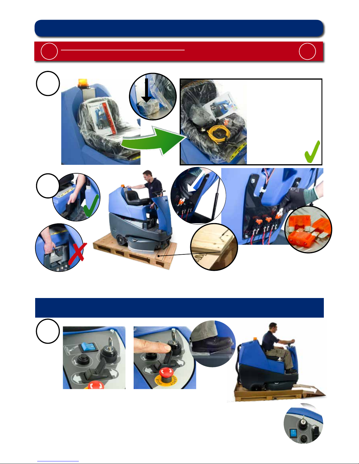
1
Contents:
1 x Operator Manual
2 x Battery charging lead
2 x Keys
4 x 40 amp fuses (1 x spare)
2 x Side pod skirts
1 x Brake disengage key
1 x Maxi fuse-puller
Fig.1
Note: Ensure that no metal objects come into contact with battery terminals while the batteries are exposed.
When inserting the rst fuse you may notice a spark, this is normal.
Lift top tank assembly to reveal battery compartment.
Always lift between points as illustrated to ensure personal safety (Fig.1a).
Fit battery fuses (contained in start-up pack) into the battery fuse holders as illustrated (Fig.2).
Remove transit block from pallet (g 2a).
3
Insert key (Fig.3) into ignition and turn quarter-turn clockwise to the ‘On’ position.
Ensure that the forward/reverse switch is set to forward (Fig.4).
Depress accelerator pedal with right foot and slowly drive machine off of the pallet
using the ramp provided (Fig.5).
Note: The seat is tted with a pressure sensor that disables the machine until an operator
is seated.
When the machine is removed and in a safe position, turn key back to the off position (Fig.6).
Fig.6
Please read before commencing any operation.
After the removal of all the packaging, carefully open and check the contents of the start up pack (Fig.1).
!
!
Quick Set Up Guide
2
Fig.2a
Fig.1a
Fig.2
8
ALWAYS ENSURE THAT THE MACHINE IS SWITCHED OFF
BEFORE MAKING ANY ADJUSTMENTS
!
!
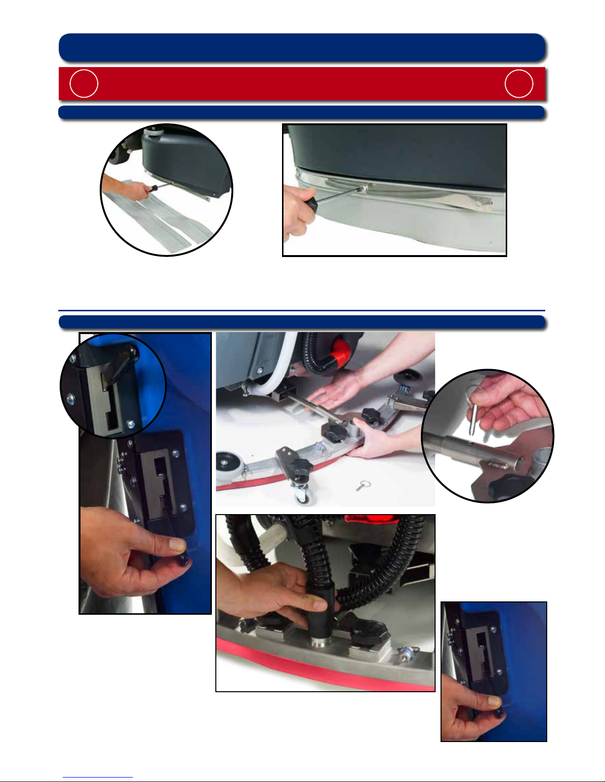
To t the side pod skirts, rst remove the steel retaining strip already tted to the pod (Fig.6a).
Align the steel retaining strip within the locating grooves of the rubber skirt and ret using existing screws (Fig.6b)
Periodically the side skirts should be examined and checked for wear and damage. Replace as shown above.
Fig.6a Fig.6b
Machine Set Up
Fitting the side pod skirts
Fitting the oor tool
Lower the oor-tool arm by moving the release lever to the upper position (Fig.7).
Push oor-tool onto the holder and secure with the easy-t securing pin (Fig.8).
Push waste collection pipe onto the oor-tool; ensure a tight t (Fig.9).
Note: Raise oor-tool again before driving to the cleaning area (Fig.9a).
Fig.7
!
Fig.8
Fig.9a
Fig.9
9
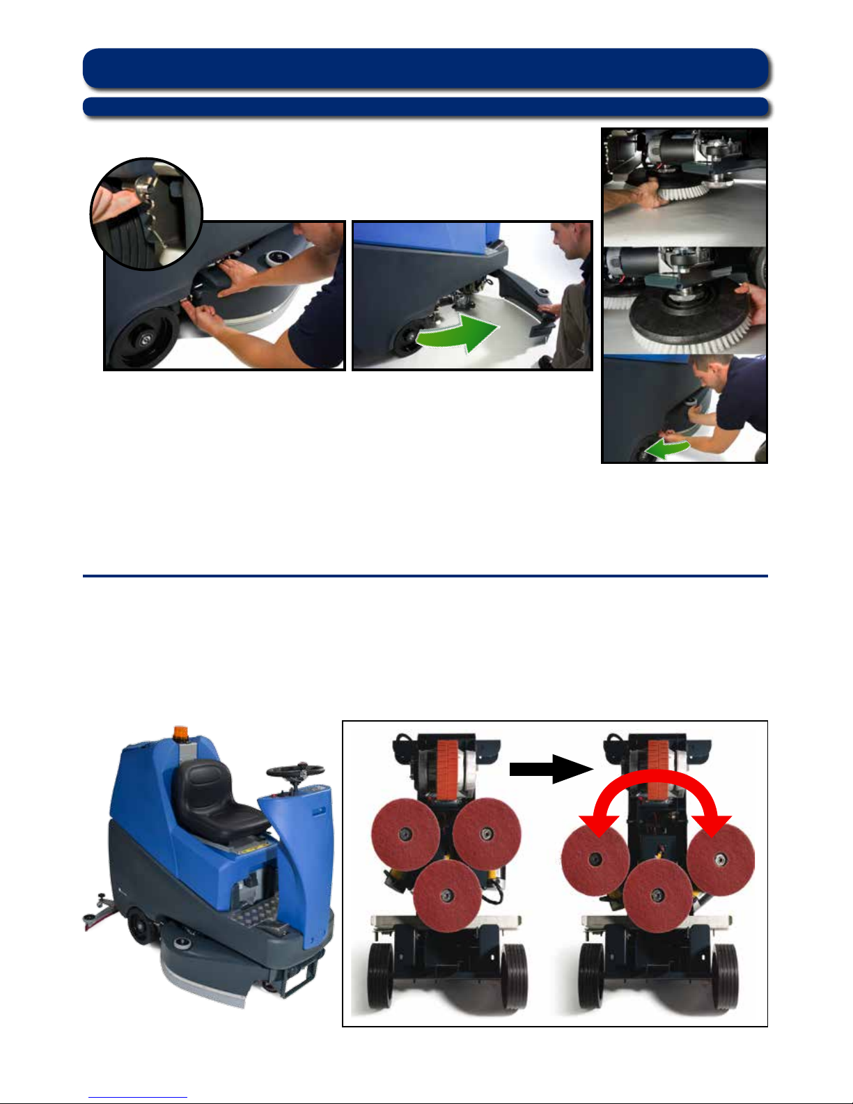
Featuring the new OBS (Octagonal Brush System);
the brushes simply push-t up onto the chucks
making tting and removal a simple process.
Pull the side pod adjustment lever and set to the top position (Fig.10).
The side pod will now pull open (Fig.11).
Fit middle brush rst (brushes will click-t onto the OBS drive chuck).
Fit outer brush next on both sides.
Close side pod and while keeping the side pod pushed in, set to
appropriate width (see setting the width) (Fig.12).
Safety gloves are recommended for the changing of used brushes.
Owning the TTV-678 ride on scrubber dryer is like having 3 machines in one.
With three width-settings the operator can quickly adapt the machine to any cleaning situation;
without the need for any tools. The machine can be set to clean anything from a narrow corridor to
a large warehouse. The TTV-678 is a totally versatile machine.
Fig.10 Fig.11
Fig.12
Machine Set Up
Fitting the brushes
10
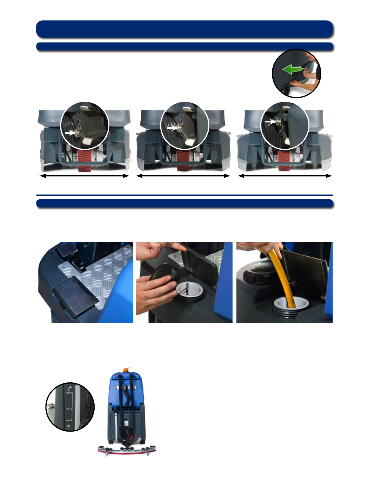
Setting the width adjustment
First push the side pod in (see Fig.13), then pull the side pod adjustment lever
and set it to one of the three width-settings (see Fig.13a) Repeat the
operation on both sides.
650mm 750mm 850mm
Fig.13
Fig.14
Fig.16a
Fig.13a
The TTV-678 is equipped with a large capacity 110 litre clean-water tank allowing, for large areas to be covered in
a single ll.
To ll the clean-water tank, lift the cover ap (Fig.14) to expose the ller cap.
Unscrew the ller cap (Fig.15) and ll the tank using a hose (Fig.16) or preferred method.
Note: Great care must be taken to ensure that contaminants (leaves, hair, dirt, etc.) are not allowed to enter the
clean-water tank during the lling process. If using a bucket or similar, ensure it is always clean and free from
debris.
Fill-level indicator
The water level in the clean water tank can be measured using the
scale on the rear of the machine (Fig.16a).
Machine Set Up
Filling the clean water tank
Fig.15 Fig.16
 Loading...