

Nacecare Numatic TT 516 Owner's Instructions Manual
Owner Instructions
Mode d’emploi
T T 516
(TT 1840)
Original Instructions
Warning! Read instructions before using the machine.
Attention
Lisez la notice avant d’utiliser la machine.
2
20
21
19
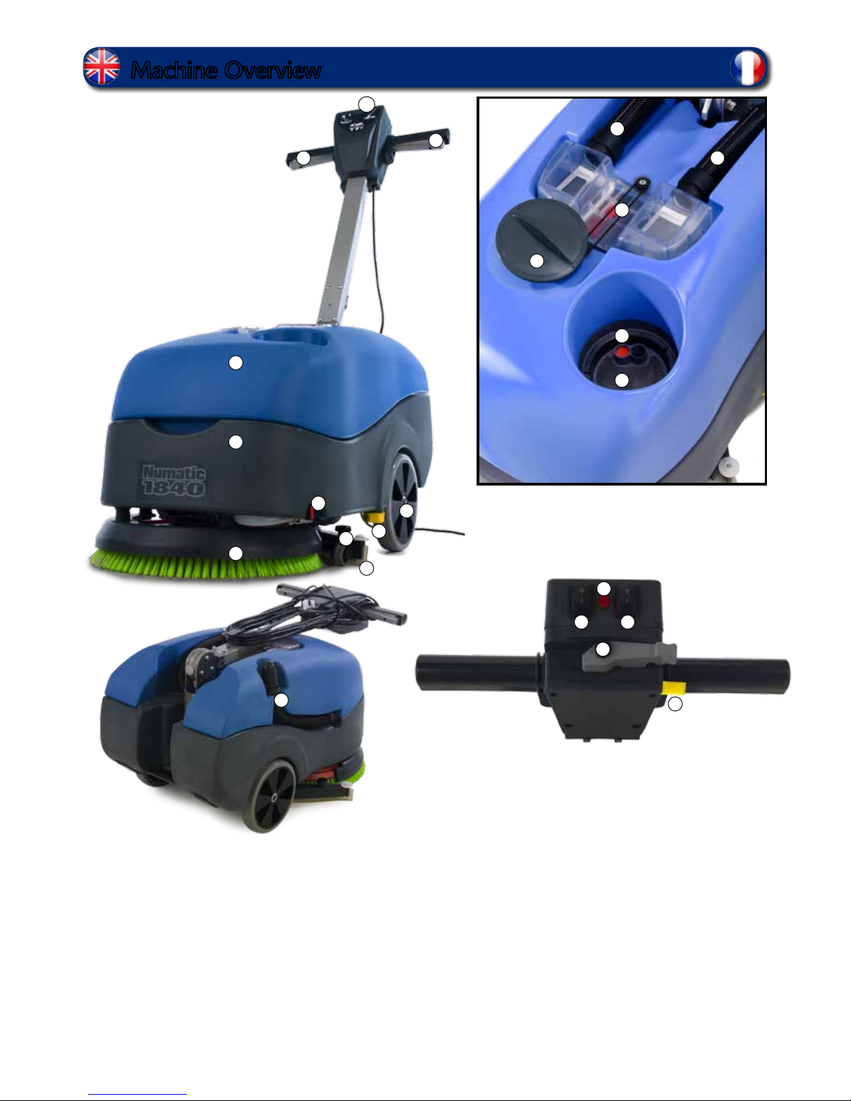
Machine Overview
1. Operator control panel
2. On / Off Lever
3. Waste water tank
4. Clean water tank
5. Brush deck
6. Squeegee blades
7. Floor-tool retaining knobs
8. Clean-water on / off tap
9. Clean-water emptying cap
10. Rear moving wheels
11. Floor-tool vacuum hose
12. Vacuum hose
13. Separator
14. Clean-water ller cap
15. Clean-water level indicator
16. Clean-water tank ll point
17. Top tank (waste water) drainage hose
18. On / Off Switch
19. Vacuum Switch
20. Pump Switch
21. Power Light
22. Handle Position lever
1
3
4
5
6
7
8
10
12
13
14
15
16
17
112
9
2
22
18
Français (voir page 16)
3
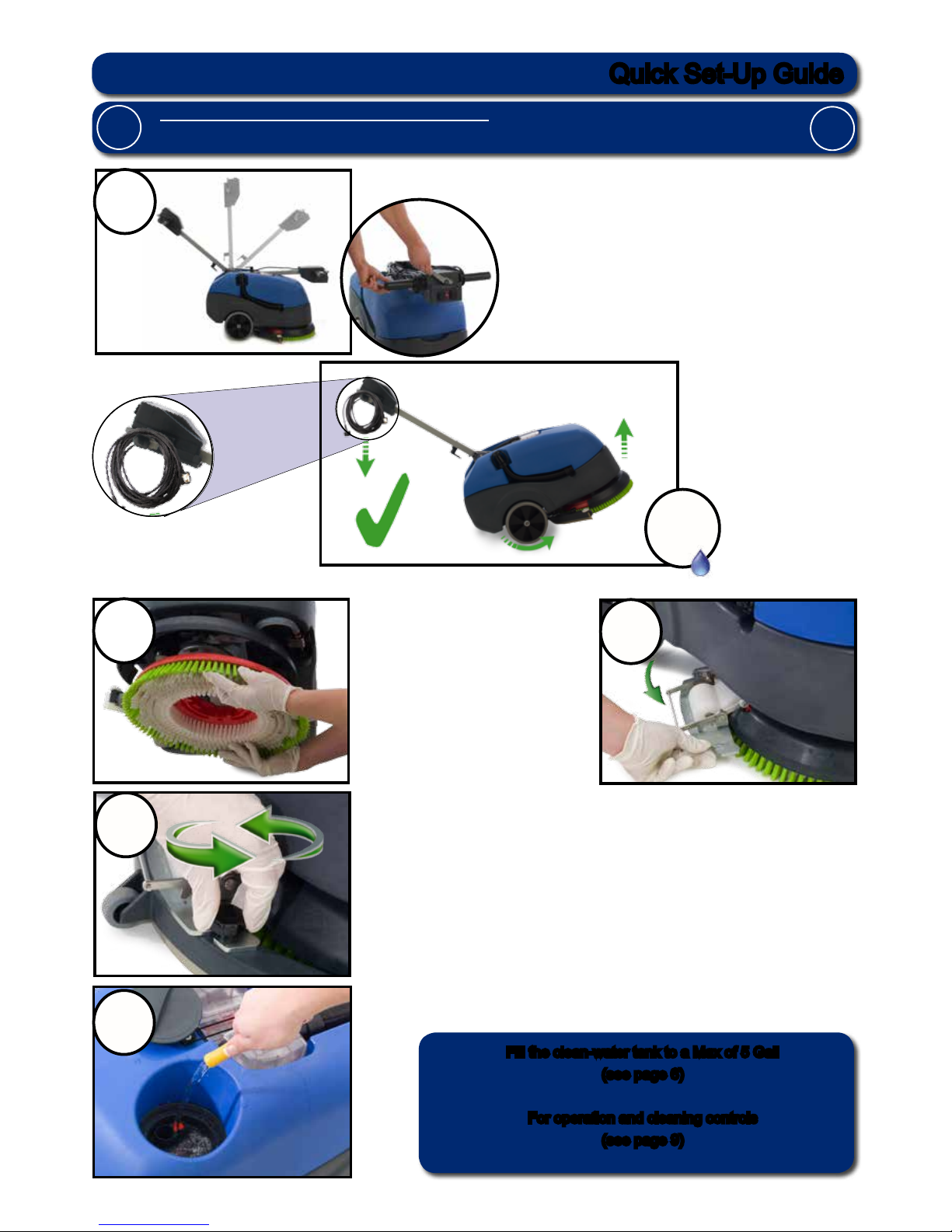
Fill using a hose, bucket or a suitable container. (Fig 5).
Please read before commencing any operation.
After the removal of all the packaging, carefully open and check the contents.
!
1
2
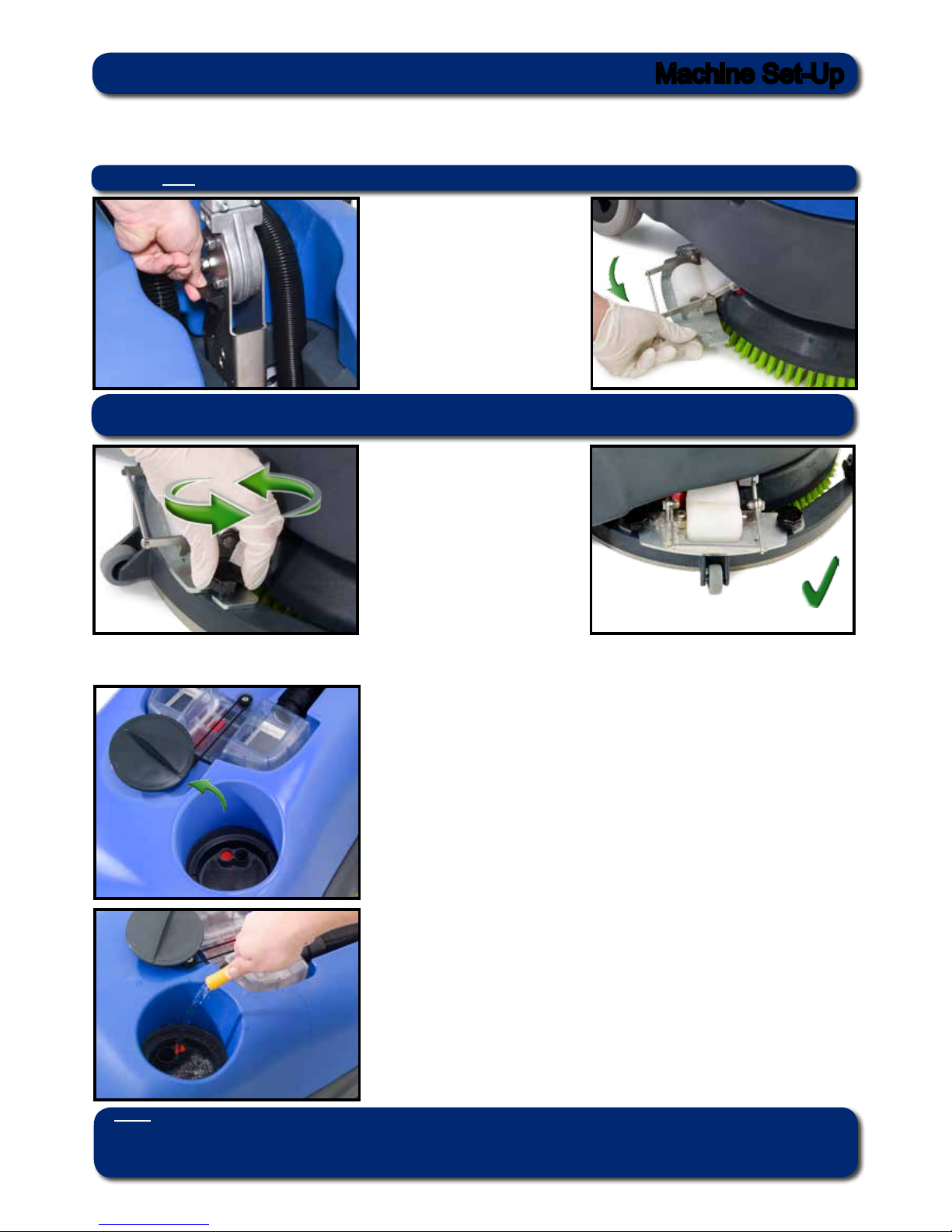
Using the handle position lever, move the handle into the
upright position. (Fig 1).
Fit the Brush / Pad (Fig 2).
Swing the oor-tool carrier from
behind the brush. (Fig 3).
4
3
5
Use the two locking knobs tted to the oor-tool, secure to the
oor-tool to the oor-tool carrier. (Fig 4).
Fill the clean-water tank to a Max of 5 Gall
(see page 6)
For operation and cleaning controls
(see page 9)
Fig 1
Fig 2
Fig 3
Fig 4
Fig 5
Quick Set-Up Guide
!
0Gall
Tip the machine.
(see Page 4)
4
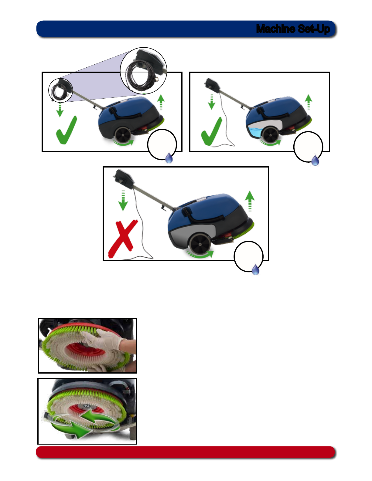
Machine Set-Up
Fitting the brushes
Slide the brush / pad under the brush deck (Fig 6).
Featuring the Nulock brush system.
The brush is tted simply by pushing and twisting to lock in place, making tting and removal a simple
process.
Fit the brush / pad onto the Nulock drive chuck, twist to lock
the brush / pad in place (Fig 7).
Only use manufacturer supplied brushes.
This machine requires a 16” brush or a 16”pad.
Fig 6
Fig 7
Safety gloves are recommended for the changing of used brushes.
Tipping the Machine
0Gall
0Gall
2Gall
Min
5
The TT 516 is equipped with a large 5 gall clean-water tank allowing large areas to be cleaning in a single ll.
Filling the clean-water tank
To ll the clean-water tank, remove the ller cap (Fig 10).
Fill using a hose, bucket or a suitable container. (Fig 11).
Note.
Great care must be taken to ensure that contaminants (leaves, hair, dirt, etc) are not allowed to enter the
clean-water tank during the lling process.
If using a bucket or similar, ensure it is always clean and free from debris.
Fig 10
Fig 11
Machine Set-Up
Fitting the Floor Tool
The oor tool has been designed for quick tting, allowing easy squeegee blade replacement and a safety knock-off
feature if the oor tool gets snagged, whilst in transit.
The oor tool carrier can be
raised and locked from moving
by operating the locking lever,
upwards and backwards.
this lever can be found next to the
lower section of the handle.
Unlock and swing the oor-tool
carrier to the side of the machine
(Fig 8).
Secure to the carrier using the
two knobs tted to the oor-tool
carrier (Fig 9) - (Fig 9a).
Do not over tighten the retaining
knobs.
Fig 9
Fig 9a
Note:
It is easier to t the oor-tool if the weight of the machine is resting on the brush. Ensure the brush is tted rst.
Fig 8
Note The lever moves upward and backward motion to lock the oortool in the raised position.
6
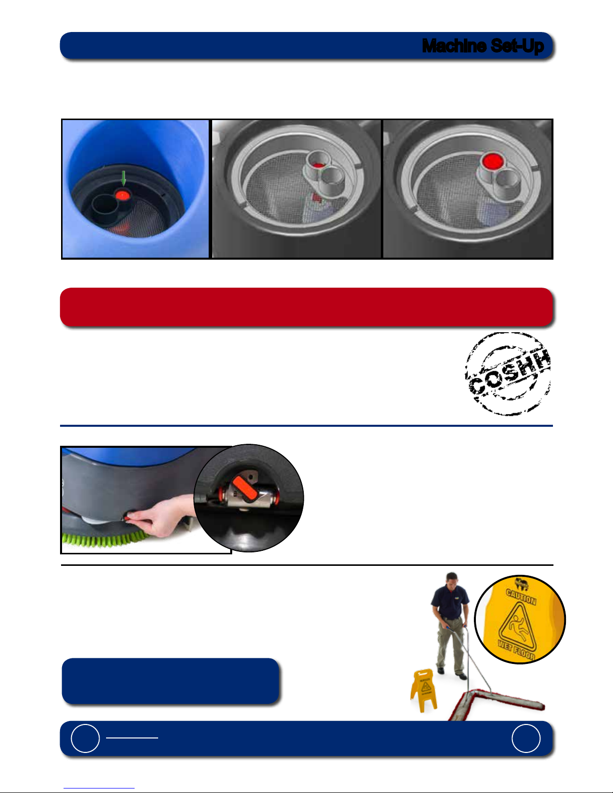
Control of Substances Hazardous to Health (COSHH)
For best results use a non-foaming type of chemical, dilute to the manufacturer’s specication.
For further guidance on hazardous substances refer to health and safety instructions online.
Water Flow Adjustment
Located on the left of the machine is the On / Off water tap
(Fig 14 / 15).
Pre-cleaning advice.
Important
Do not operate machine unless the Operator Manual has been read and fully understood.
!
!
Before performing the cleaning operation, place out
appropriate warning signs and sweep or dust-mop the oor
(Fig 16).
WHEN HANDLING AND MIXING CHEMICALS.
Always ensure that chemical manufacturer’s safety guidelines are followed.
Only use chemicals recommended for use in auto scrubber-dryers.
!
Fig 14
Fig 15
Fig 16
Numatic part (629044) Wet Floor sign
(available if required)
Machine Set-Up
Fill Level Indicator
Fill the clean water tank to a maximum of 5 gall, including cleaning chemicals if required.
Follow chemical manufacturing guide lines.
Use the ll indicator
(Fig 12).
Showing the clean-water tank full
(Fig 13a).
Fig 12
Fig 13
Fig 13a
Showing the clean-water tank empty
(Fig 13).
7
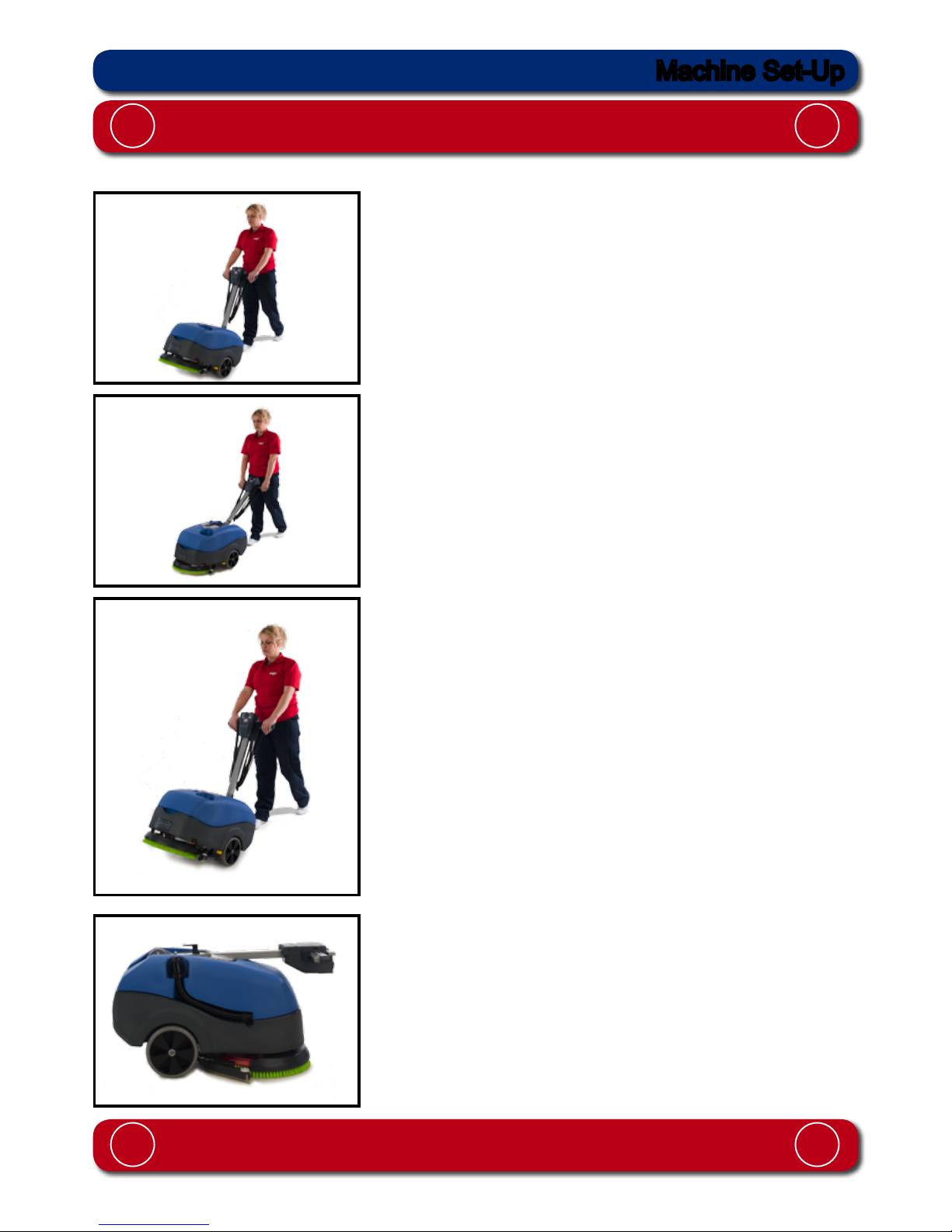
Moving the machine
Caution
When moving or lifting the TT 516, follow the national safety guidelines on lifting.
! !
When the bottom tank (clean water) is full the machine can be
tilted to a maximum of 450 (Fig 19).
When the top tank (waste water) is full the machine can be
tilted to a maximum of 10
0
for transporting to dumping area
(Fig 18).
Caution:
Ensure both tanks are empty before attempting to lift the machine.
! !
Transport the machine by tilting back on to the main transit
wheels (Fig 17).
Weight of empty machine 38.5Kg (85 lbs) g 20.
Fig 17
Fig 18
Fig 19
Fig 20
Machine Set-Up
8
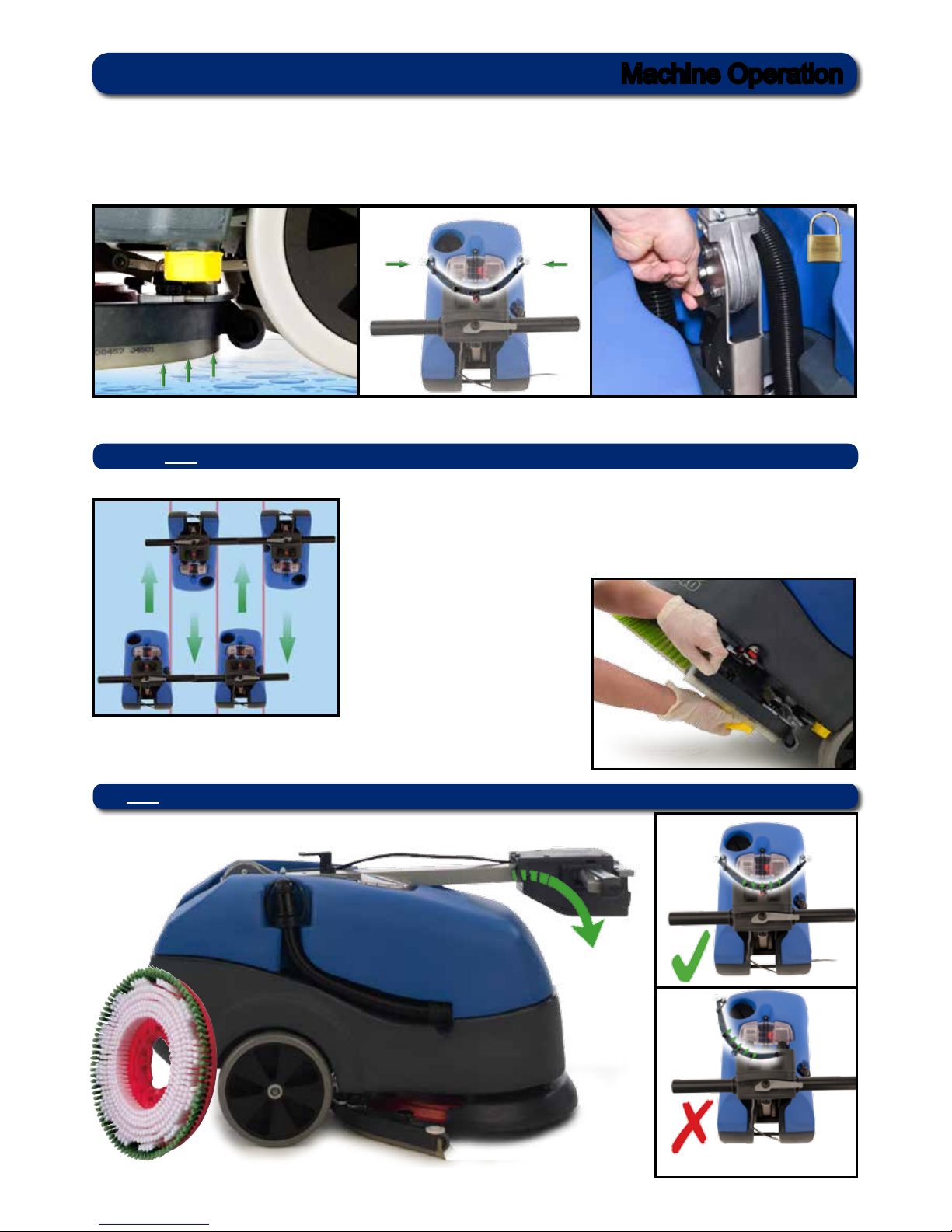
Pre-scrub mode
The TT 516 has been designed to cope with a variety of oor types and different levels of soiling.
On heavily soiled oors use a ‘double scrub’ technique.
First pre-scrub the oor with the oor-tool in the raised position (Fig 21), allow the chemical time to work, then scrub
the area a second time with the oor-tool lowered.
To raise the oor-tool, ensure the oor-tool carrier is central to the machine (Fig 22).
Lift the lever near the base of the handle and lock into position (Fig 23).
The clean-water / chemical mix is deposited via ‘THRU-FEED’ system.
The waste water is then retrieved by the oor-tool
Overlap the scrubbing path by 10cm to ensure an even clean (Fig 24).
If streaking occurs, wipe the oor-tool blades clean (Fig 25).
Floor tool in use
Note Care must be taken to reduce speed when cornering or when manoeuvring around obstacles.
Fig 21 Fig 22 Fig 23
Fig 24
Fig 25
Note The lever moves upward and backward motion to lock the oortool in the raised position.
Machine Operation
9
1 1
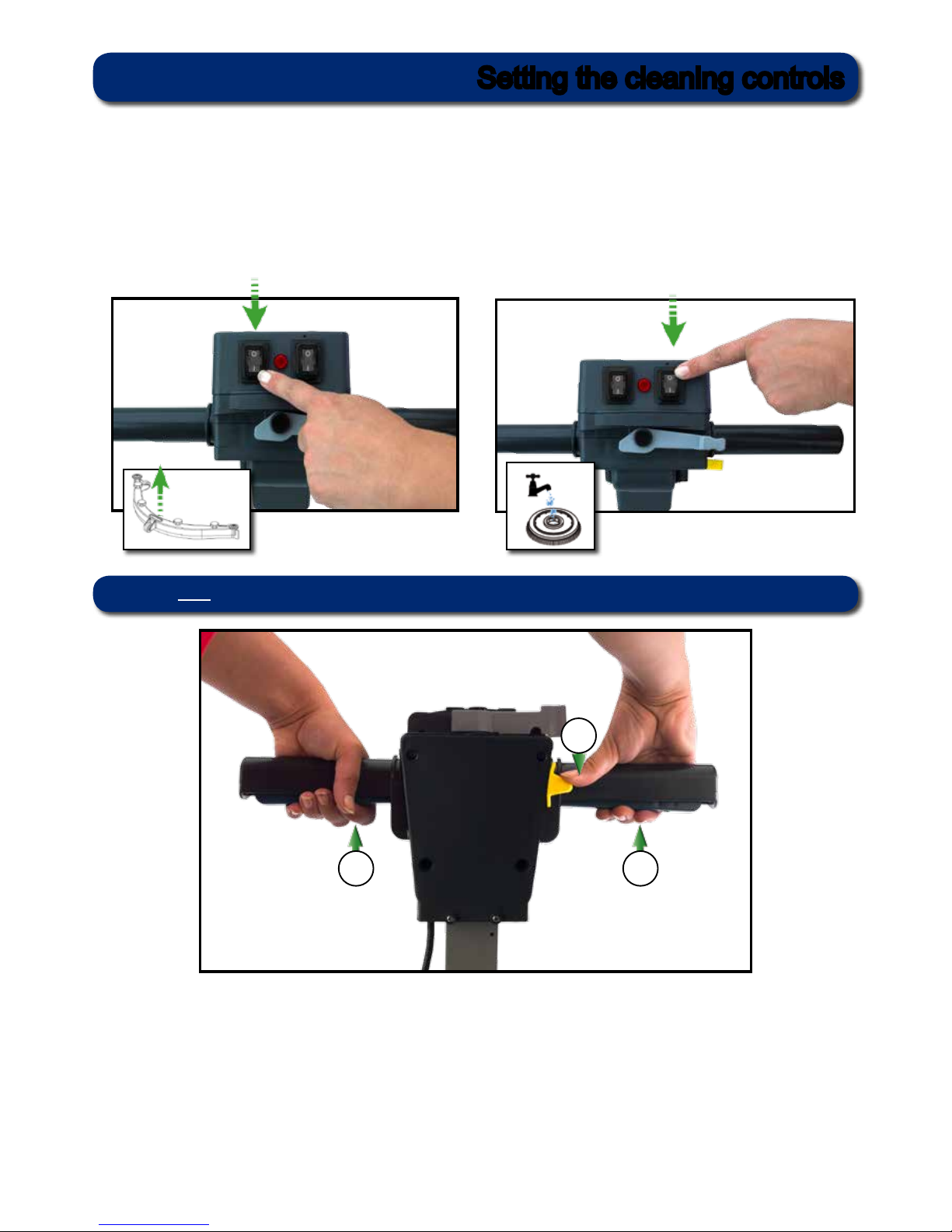
Setting the cleaning controls
To start: hold down either trigger and press the yellow start button once
2
Ensure your TT 516 machine has been plugged into a suitable power supply.
Select the desired function using the ON / OFF switches tted to the handle.
Vac Switch Pump Switch
Note: The Pump Switch will only function when the Brush is in operation.
10
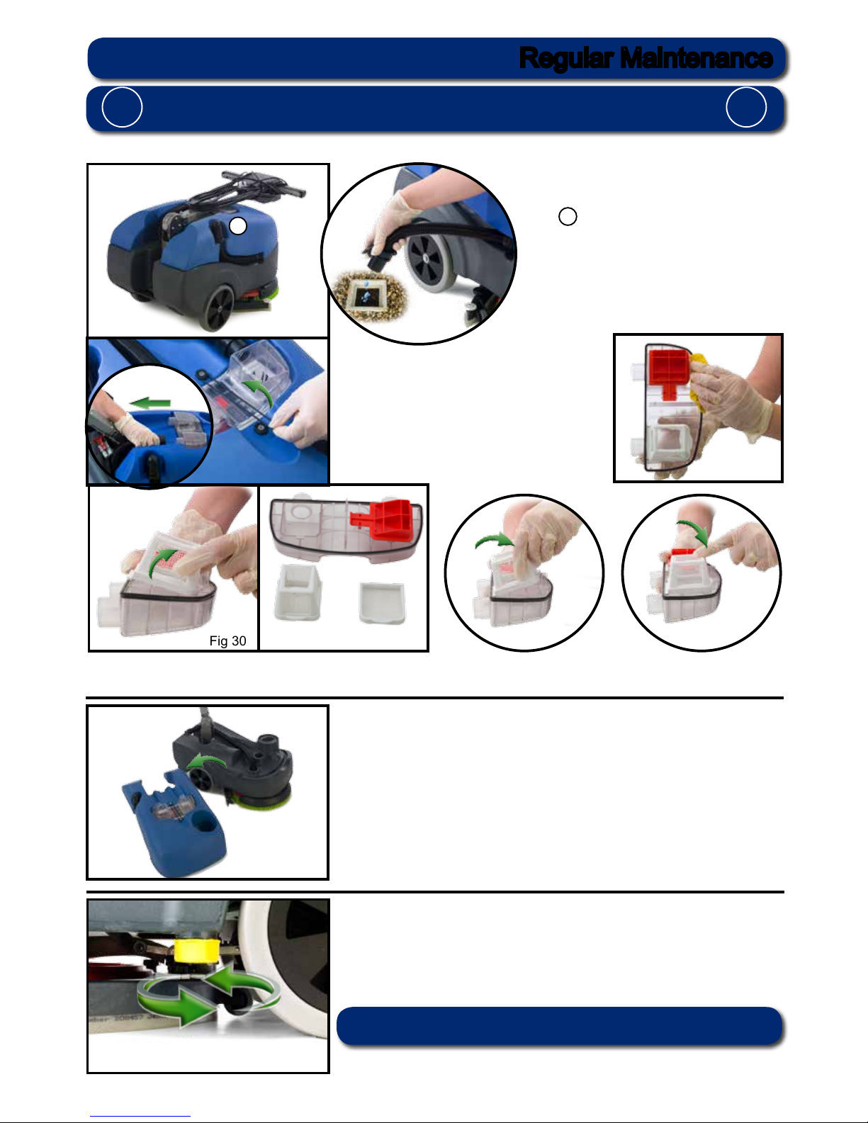
ALWAYS ENSURE THAT THE POWER SUPPLY IS DISCONNECTED,
PRIOR TO ANY MAINTENANCE OPERATION.
! !
After use, empty waste-water tank using
emptying hose and ush-out with clean
water.
A
Remove the two hoses and disconnect the
separator from the machine (Fig 28). Undo
the separator restraining strap (Fig 28a) and
lift off the separator. The separator has a
sealing-rubber which should be examined at
every clean-down (Fig 29).
Rinse using clean water.
NOTE:
Avoid over tightening the clean water draining cap.
The TT 516 has been designed with ease of use in mind, this included easy stripping-down and cleaning.
Remove the two lters clipped into the separator and ush with clean water (Fig 30)(Fig 30a).
Replace by tting the rear of the lter rst then clipping the front to lock in place (Fig 31) (Fig 32).
Once emptied the top waste-water tank can simply be lifted off. (Fig 33).
The clean-water tank can be drained via the yellow cap tted to the left
hand side of the machine. The cap has a rubber seal and might require a
spanner to remove. (Fig 34).
Fig 28
Fig 29
Fig 30 Fig 31
Fig 32
Fig 34
A
Fig 30a
Fig 33
Regular Maintenance
Fig 28a
 Loading...