

Page 1

Operating Instructions
Chamber Furnaces for Annealing,
Hardening and Brazing
N 7/H - N 87/H
-> 01.2016
Original instructions
www.nabertherm.com
Made
in
Germany
Page 2

Copyright
Copyright by
Nabertherm GmbH
Bahnhofstrasse 20
28865 Lilienthal
Federal Republic of Germany
Reg: M01.0071 ENGLISCH
Rev: 2016-06
No responsibility is accepted for the correctness of this information. We
reserve the right to make technical alterations.
2
Page 3

1 Introduction ........................................................................................................................................................... 5
1.1 Product Description ........................................................................................................................................... 6
1.2 Overview of the Complete Furnace ................................................................................................................... 8
1.3 Safeguarding against Dangers Posed by Over-Temperature ........................................................................... 12
1.3.1 Key to the Model Names ............................................................................................................................ 13
1.4 Scope of Delivery ............................................................................................................................................ 13
2 Specifications ....................................................................................................................................................... 15
2.1 Warranty and Liability .................................................................................................................................... 16
3 Safety .................................................................................................................................................................... 16
3.1 Intended Use.................................................................................................................................................... 16
3.2 Requirements for the Furnace Operator .......................................................................................................... 18
3.3 Requirements for the Operating Personnel ...................................................................................................... 19
3.4 Protective Clothing .......................................................................................................................................... 20
3.5 Basic Measures During Normal Operation ..................................................................................................... 21
3.6 Basic Measures in Case of Emergency ........................................................................................................... 21
3.6.1 What to do in an Emergency ....................................................................................................................... 21
3.7 Basic Measures for Servicing and Maintenance.............................................................................................. 23
3.8 Environmental Regulations ............................................................................................................................. 24
3.9 Explanation of the Symbols and Warnings ..................................................................................................... 24
3.10 General Risks with the Furnace ....................................................................................................................... 28
4 Transportation, Installation, and Commissioning ............................................................................................ 30
4.1 Delivery ........................................................................................................................................................... 30
4.2 Unpacking (N 7/H - N 17/HR) ........................................................................................................................ 33
4.3 Unpacking (N 31/H - N 87/H) ......................................................................................................................... 34
4.4 Transportation Securing Equipment/Packaging .............................................................................................. 36
4.5 Constructional and Connection Requirements ................................................................................................ 36
4.5.1 Installation (Furnace Location) ................................................................................................................... 36
4.6 Assembly, Installation, and Connection .......................................................................................................... 38
4.6.1 Venting Exhaust Fumes .............................................................................................................................. 38
4.6.2 Insertion of the Base Plate .......................................................................................................................... 39
4.6.3 Assembling the Controller (Depending on the Model) ............................................................................... 40
4.7 Installation of an Extraction Flue, Extraction Flue with Fan or Extraction Flue with Fan and Catalyst
(Accessories for N 7/H – N 17/HR) .............................................................................................................................. 42
4.7.1 Connecting the Furnace to the Power Supply ............................................................................................. 43
4.8 Commissioning ............................................................................................................................................... 46
4.9 Loading/Charging ........................................................................................................................................... 47
4.10 Recommendations for Heating the Furnace for the First Time ....................................................................... 48
5 Operation ............................................................................................................................................................. 49
5.1 Controller ........................................................................................................................................................ 49
6 Operation, Display and Switch Elements (depending on design) .................................................................... 50
6.1 Turning on the Controller/Furnace .................................................................................................................. 50
6.2 Turning off the Controller/Furnace ................................................................................................................. 51
6.2.1 Handling the Controller .............................................................................................................................. 52
6.3 Opening and Closing the Door ........................................................................................................................ 52
6.3.1 Charging Plate ............................................................................................................................................ 53
3
Page 4

6.4 Operation with Heat Treatment Accessories ................................................................................................... 54
7 Servicing, Cleaning, and Maintenance .............................................................................................................. 55
7.1 Furnace Insulation ........................................................................................................................................... 56
7.2 Shutting Down the Furnace for Servicing, Cleaning, and Maintenance ......................................................... 57
7.3 Regular Maintenance Tasks for the Entire System ......................................................................................... 58
7.4 Regular Maintenance of the Furnace ............................................................................................................... 58
7.5 Regular Maintenance Tasks – Switchgear ...................................................................................................... 59
7.6 Regular Maintenance Tasks – Electrical Testing ............................................................................................ 61
7.7 Regular Maintenance Tasks – Documentation ................................................................................................ 62
7.8 Cleaning Products ........................................................................................................................................... 63
8 Malfunctions ........................................................................................................................................................ 64
8.1 Error Messages of the Controller .................................................................................................................... 64
8.2 Warnings of the Controller .............................................................................................................................. 67
8.3 Malfunctions of the Switchgear ...................................................................................................................... 68
8.4 Controller Check List ...................................................................................................................................... 70
9 Spare Parts/Wearing Parts ................................................................................................................................. 72
9.1 Replacing a Heating Element .......................................................................................................................... 76
9.2 Replacing a Thermocouple .............................................................................................................................. 81
9.3 Electrical Schematics/Pneumatic Schematics ................................................................................................. 83
10 Nabertherm Service ............................................................................................................................................ 83
11 Shut-Down, Dismantling, and Storage............................................................................................................... 84
11.1 Transportation/Return Transportation ............................................................................................................. 85
12 Declaration of Conformity .................................................................................................................................. 86
4
Page 5
Pos: 1 /TD/Einleitung/Überschrift - Einleitung 1 @ 0\ mod_1167823212238_51.docx @ 5139 @ 1 @ 1
1 Introduction
Pos: 2 /TD/Einleitung/Öfen @ 0\mod_1158157227533_51. d ocx @ 2084 @ @ 1
Dear Customer,
Thank you for choosing a quality product from Nabertherm GmbH.
You can be proud that you have chosen a furnace which has been especially tailored to suit
your manufacturing and production conditions.
This product is characterized by
professional workmanship
high performance due to its high efficiency
high-quality insulation
low power consumption
low noise level
simple installation
easy to maintain
high availability of spare parts
Your Nabertherm Team
Pos: 3 /TD/Einleitung/Die in der Anleitung gezeigte n Abbi ldungen können abhängig von Funktion, ... Ofenmodell abweichen @ 24\mod_1337854352242_51.docx @ 161605 @ @ 1
Note
These documents are intended only for buyers of our products and may not be copied or
disclosed to third parties without our written consent. (Law governing copyright and
associated protective rights, German Copyright Law from Sept. 9, 1965)
Protective Rights
Nabertherm GmbH owns all rights to drawings, other documents and authorizations, also in
case of applications for protective rights.
Note
All the figures in the instructions have a descriptive character; in other words, they do not
represent the exact details of the furnace.
Note
The pictures contained in the instruction manual may contain inaccuracies in terms of the
function, design and furnace model.
5
Page 6

Pos: 4 /TD/Einleitung/Produktbeschreibung/Öfen/ Überschrift - Produktbeschreibung 1.1 @ 0\mod_116 7821943807_51.docx @ 5103 @ 2 @ 1
1.1 Product Description
Pos: 5 /TD/Einleitung/Produktbeschreibung/Öfen/ Produktbeschreibung-Bei diesen elektri sch beheizten Öfen handelt es sich um ein Qualitätsproduk t ... @ 15\mod_1305707254935_51.docx @ 117576 @ @ 1
These electrically heated furnaces are a high-quality product which will give you many
years of reliable service if they are properly cared for and maintained. One basic
prerequisite is that the furnace is used the way it was designed to be used.
During development and production a high priority was placed on safety, functionality and
economy.
Pos: 6 /TD/Einleitung/Produktbeschreibung/Öfen/ Produktbeschreibung-Grundaufbau-Kam merof en N7/H - N 87/H_Dental und Laborbereich @ 123\mod_1465207 377133_51.docx @ 544234 @ @ 1
Pos: 7 /TD/Einleitung/Produktbeschreibung/ Öfen/ Überschrift - Zusätzlich zeichnet sich dieses Pr odukt aus durch: @ 15\mod_1305713428306_51.doc x @ 117724 @ @ 1
Pos: 8 /TD/Einleitung/Produktbeschreibung/Öfen/ Produktbeschreibung-Zusätzlich zeic hnet ...: Kammerofen N7/H - N 87/H (Modell 2015) - Katalog @ 123\mod_1465207169834_51.docx @ 544008 @ @ 1
Pos: 9 /TD/Einleitung/Produktbeschreibung/Öfen/ Produktbeschreibung-Zusätzlich zeic hnet ...: Kammerofen N7/H - N 87/H (Modell 2015) - Ofenspezifisch @ 123\mod_1465287126336_51.docx @ 545416 @ @ 1
Pos: 10 /TD/Einleitung/Produktbeschreibung/ Öfen/Überschrift - Zusatzausstattung (Einzug Mitte) @ 39\mod_1364984085402_51.docx @ 221200 @ @ 1
Pos: 11 /TD/Einleitung/Produktbeschreibung/ Öfen/Produktbeschreibung - Zusatzausstattung: Temperaturwählbegrenzer mit einstellbarer ... @ 116\mod_1459332570794 _51.docx @ 459785 @ @ 1
Pos: 12 /TD/Einleitung/Produktbeschreibung/ Öfen/Produktbeschreibung - Zubehör: Prozessste uer ung und -dokumentation über VCD-Softwarepaket zur Über wa @ 116\mod_1459332710604_51.docx @ 459839 @ @ 1
Pos: 13 /TD/Einleitung/Produktbeschreibung/ Öfen/Überschrift - Zubehör (Einzug Mitte) @ 36\mod_1359 971094458_51.docx @ 208406 @ @ 1
Pos: 14 /TD/Einleitung/Produktbeschreibung/ Öfen/Produktbeschreibung - Zubehör: Abzugskamin mit Ventilator oder Katalysator (nicht für N 31/H-N 87/ H) @ 123\mod_1465378085414_51.docx @ 546202 @ @ 1
Pos: 15 /TD/Einleitung/Produktbeschreibung/ Öfen/Produktbeschreibung - Zubehör: NTLog für Naber ther m-Controller: Aufzeichnen...Prozessdaten mit USB-S @ 123\mod_1465287433347_51.docx @ 545442 @ @ 1
Pos: 16 /TD/Einleitung/Produktbeschreibung/ Öfen/Produktbeschreibung - Zubehör: Chargierpla tte @ 123\mod_1465287709579_51.docx @ 545468 @ @ 1
Pos: 17 /TD/Einleitung/Produktbeschreibung/ Öfen/Produktbeschreibung - Zubehör: Glüh- und Härtef olien @ 123\mod_1465287729726_51.docx @ 545494 @ @ 1
Pos: 18 /TD/Einleitung/Produktbeschreibung/ Öfen/Produktbeschreibung - Zubehör: Begasungskäs ten für Schutzgasatmosphäre mit zusätzlichem Char gen therm @ 123\mod_1465287732847_51.docx @ 545520 @ @ 1
Pos: 19 /TD/Einleitung/Produktbeschreibung/ Öfen/Produktbeschreibung - Zubehör: Manuelles oder automatisches Begasungssystem. @ 116\mod_14593 32575272_51.docx @ 459812 @ @ 1
Pos: 20 /TD/Einleitung/Produktbeschreibung/ Öfen/Produktbeschreibung - Zubehör: Schutzgashär tesystem @ 123\mod_1465287735885_51.docx @ 545546 @ @ 1
These universal chamber furnaces with radiation heating are designed for tough heat
treatment applications. They are perfect for processes in toolmaking and in the hardening
shop, such as annealing, hardening and forging. A wide variety of accessories enables these
furnaces to be tailored to the relevant application.
Other Characteristics of this Product are:
Heating from three sides (both sides and the floor)
Heating elements on carrier tubes ensure free heat radiation and a long service life
Bottom heating protected by heat-resistant SiC tiles
Multi-layer insulation with high-quality refractory insulation inside the furnace
Exhaust air opening on the left side of the furnace, from N 31/H in the rear wall
Models N 7/H – N 17/HR are designed as tabletop models
Base included from model N 31/H
Parallel swing door, which opens downward; if required, also available with lift door
that opens upward (N 31/H to N 87/H)
Top part of door with stainless steel plates to prevent burning when the door is opened
at high temperatures (from model N 31/H)
Temperature uniformity according to DIN 17052-1 to +/- 10 °C
Door movement cushioned with gas springs (from model N 31/H)
Additional Equipment
Over-temperature limiter with adjustable cutout temperature for thermal protection
class 2 in accordance with EN 60519-2 as temperature limiter to protect the furnace
and load
Process control and documentation via VCD software package for monitoring,
documentation and control
Accessories
Extraction flue with fan or catalyst (not for model N 31/H – N 87/H)
NTLog for Nabertherm controller: Recording process data with a USB flash drive
Charging plate
Annealing and hardening foil
Protective gas boxes for protective gas atmosphere with additional charge
thermocouple Type K
Manual or automatic gas supply system
Protective gas hardening system
6
Page 7

Pos: 21 /TD/Einleitung/Produktbeschreibung/ Öfen/Produktbeschreibung - Zubehör: Digitales Temperaturmessgerät zur Messung der Temperatur im Begasun gs @ 123\mod_1465287738965_51.docx @ 545572 @ @ 1
Pos: 22 /TD/Einleitung/Produktbeschreibung/ Öfen/Produktbeschreibung - Zubehör: Rollengäng e @ 123\ mod_1465287743003_51.docx @ 545598 @ @ 1
Pos: 23 /TD/Einleitung/Produktbeschreibung/ Öfen/Produktbeschreibung - Zubehör: Kühlstation @ 123\ mod_1465288243136_51.docx @ 545624 @ @ 1
Digital temperature measurement device to measure the temperature in the protective
gas boxes
Roller conveyors
Cooling station
7
Page 8
Pos: 24 /TD/Einleitung/Lieferumfang/Öfen/Üb er schrift - Gesamtübersicht der Anlage @ 1\mod_1174302 6369 92_51.docx @ 11332 @ 2 @ 1
1.2 Overview of the Complete Furnace
Pos: 25 /TD/Einleitung/Lieferumfang/Öfen/Üb er schrift - Ofenmodell N 7/H - N 17/HR (Einzug links) @ 122\mod_146 4942440905_51.docx @ 543106 @ @ 1
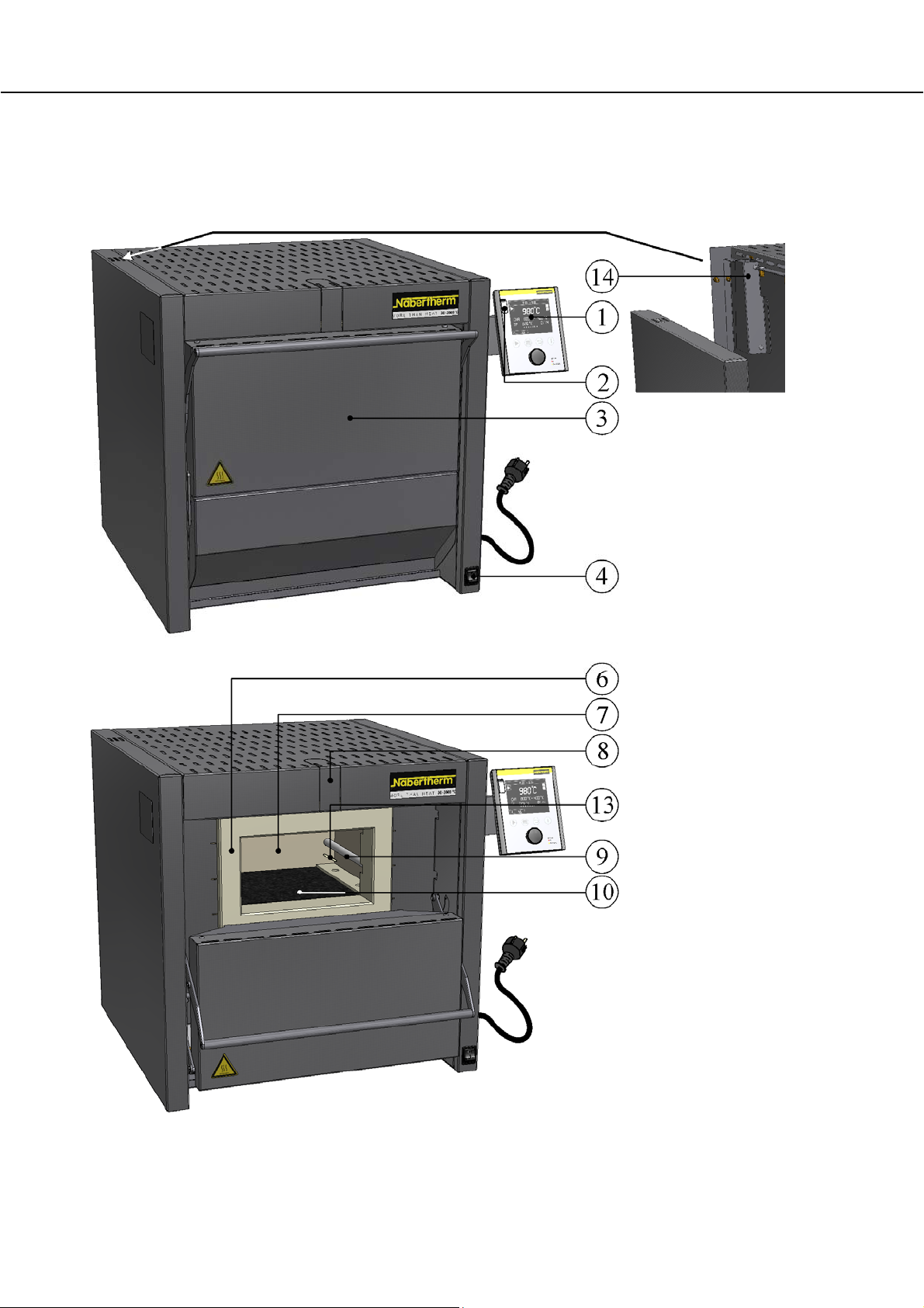
Furnace model N 7/H – N17/HR (similar to picture)
Pos: 26 /TD/Einleitung/Lieferumfang/Öfen/Ge sa mtübersicht Kammerofen N 7/H (Modell 2015) @ 123\mod_1464 942615333_51.docx @ 543132 @ @ 1
Fig. 1: Overview: Example shows chamber furnace N 7/H (table-top model) (similar to picture)
8
Page 9
Pos: 27 /TD/Einleitung/Lieferumfang/Öfen/Üb er schrift - Ofenmodell N 31/H - N 87/H (Einzug links) @ 123\mod_14 64942752748_51.docx @ 543184 @ @ 1
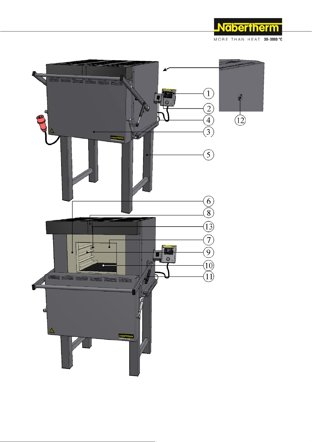
Furnace model N 31/H - N 87/H (similar to picture)
Pos: 28 /TD/Einleitung/Lieferumfang/Öfen/Ge sa mtübersicht Kammerofen N 41/H (Modell 2015) @ 123\mod_146 4942670128_51.docx @ 543158 @ @ 1
Fig. 2: Overview: Example chamber furnace N 41/H (similar to picture)
9
Page 10
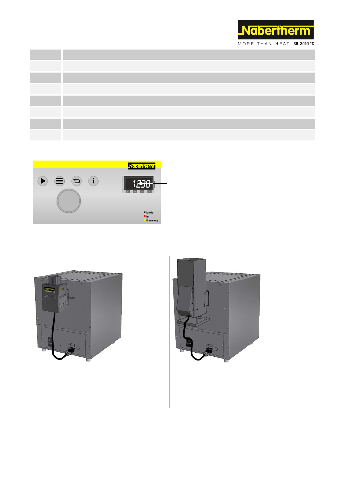
Pos: 29 /TD/Einleitung/Lieferumfang/Öfen/Ge sa mtübersicht Rückansicht N 7/H - N 17/HR - Kammerofen (Model l 201 5) @ 123\mod_1464951930103_51.docx @ 543370 @ @ 1
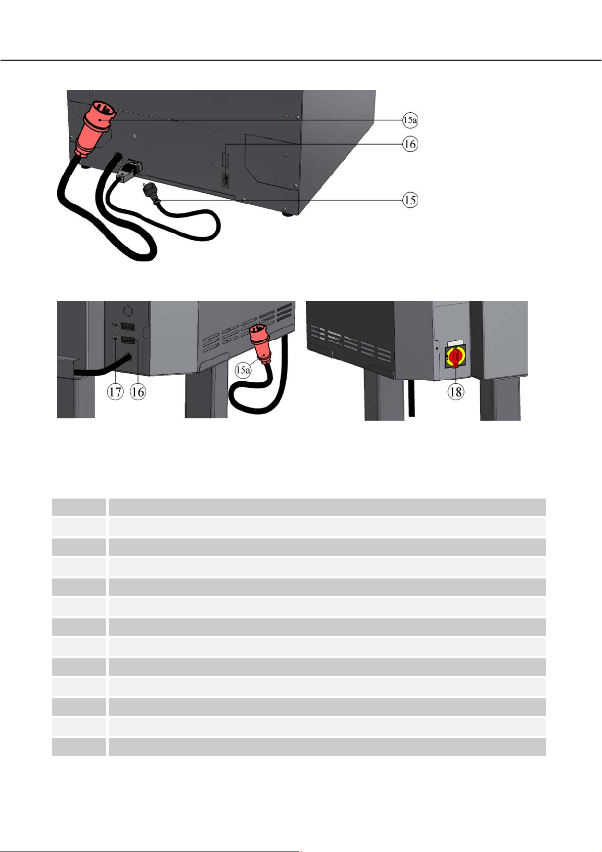
Fig. 3: Chamber furnace, rear view N 7/H – N 17/HR (similar to picture)
Pos: 30 /TD/Einleitung/Lieferumfang/Öfen/Ge sa mtübersicht Rückansicht N 31/H - N 87/H - Kammerofen (Modell 20 15) @ 123\mod_1465198382694_51.docx @ 543982 @ @ 1
Furnace model N 31/H – N 87/H with power supply
cable (depending on connection voltage)
Furnace model N 31/H – N 87/H with fixed
power connection and main switch (depending on
connection voltage)
Fig. 4: Chamber furnace, rear view N 31/H – N 87/H (similar to picture)
Pos: 31 /TD/Einleitung/Lieferumfang/Öfen/Ge sa mtübersicht_M01.0071_Tabelle Nr. und Benennung der verbauten Teile für N 7H - N87/H @ 122\mod_1464256548621_51. doc x @ 541668 @ @ 1
No. Name
1
2
3
4
5
6
7
8
9
10
Controller B400/C440/P470 (depending on model)
USB interface (NTLog for Nabertherm Controller: Recording Process Data with a USB Flash Drive)
Parallel swing door, opens downward
Power switch with integrated fuse (switching furnace on/off)
Base included from model N 31/H
Multi-layer insulation with high-quality refractory insulation inside the furnace
Furnace chamber
Opening for a gas supply system (remove perforation)
Heating elements on carrier tubes ensure free heat radiation and a long service life
Bottom heating protected by heat-resistant SiC tiles
11
12
10
Door movement cushioned with gas springs (from model N 31/H – N 87/H)
Exhaust air opening
Page 11
No. Name
13
14
15
15a
16
17
18
Pos: 32 /TD/Einleitung/Produktbeschreibung/ Öfen/Überschrift - Zusatzausstattung (Einzug lin ks) @ 36\mod_1360061559626_51.docx @ 208485 @ @ 1
Additional Equipment
Pos: 33 /TD/Einleitung/Lieferumfang/Öfen/Ge sa mtübersicht Zusatzausstattung_Zubehör: TW B-TWW_B410_C450_P480 (Modell 2015) @ 116\mod_145881006085 9_51.docx @ 458551 @ @ 1
Thermocouple
Extraction flue (Model N 7/H – N 17/HR)
Power plug with snap-in coupling (to 3600 watts)
CEE power plug (from 3600 watts) (depending on connection voltage)
Additional power connection (for accessories)
Fuse for additional power connection (for accessories)
Main switch (depending on connection voltage)
Fig. 5: Example (similar to picture)
Pos: 34 /TD/Einleitung/Produktbeschreibung/ Öfen/Überschrift - Zubehör (Einzug links) @ 53\mod_138 9868020284_51.docx @ 263175 @ @ 1
Accessories
Pos: 35 /TD/Einleitung/Lieferumfang/Öfen/Ge sa mtübersicht Zusatzausstattung_Zubehör: A bzugsk amine_Katalysatoren (N 7/H - N 17/HR) @ 123\mod_146537 8887405_51.docx @ 546228 @ @ 1
Over-temperature limiter with adjustable cutout
temperature for thermal protection class 2 in accordance
with EN 60519-2 as temperature limiter to protect the
furnace and load
Extraction flue with fan, to improve extraction of
exhaust gases from the furnace. Can be switched with
Controller B400 - P480, depending on the program (only
for N 7/H – N 17/HR)
Catalyst to clean organic components in the exhaust air. The
organic components are catalytically incinerated at approx.
600 °C; i.e. separated into carbon dioxide and steam. This
largely eliminates smells. With Controllers B400 - C440, the
catalyst can be switched in relation to the program (only for
N 7/H – N 17/HR)
*Note: If other controllers are used, an adapter cable must be ordered for connection to a separate socket. The device is
activated when it is plugged in.
Fig. 6: Example: (similar to picture)
11
Page 12
Pos: 36 /TD/Einleitung/Produktbeschreibung/ Öfen/Überschrift - Absicherung von Gefahren bei Übert emperatur @ 37\mod_1362489730884_51.docx @ 213987 @ 2 @ 1
Safety control circuit
1.3 Safeguarding against Dangers Posed by Over-Temperature
Pos: 37 /TD/Einleitung/Produktbeschreibung/ Öfen/Sicherheitseinrichtung - Überwachung der Ofenr aumtemperatur (TWB-TWW) - Beschreibung @ 37\mod_1 3624 91214270_51.docx @ 214092 @ @ 1
Over-temperature limiters with manual reset/with automatic reset to protect against overtemperature in the furnace chamber are available for Nabertherm GmbH furnaces either as
a standard feature (depending on the model series) or as additional equipment (customized
design).
The over-temperature limiter with manual reset/with automatic reset monitors the furnace
chamber temperature. The display shows the most recently set cut-off temperature. If the
furnace chamber temperature rises about the pre-set cut-off temperature the heating is shut
Pos: 38 /TD/Sicherheit/Sicherheitssymbole/W arnhinweise-ISO-ANSI/Warnsymbol_Gefahr - Absicherung von Gefahren bei Übertemperatur am TWB- TWW @ 37\mod_1362490404893_51.docx @ 214067 @ @ 1
down to protect the furnace, the charge and/or the operating equipment.
DANGER
• Danger caused by incorrectly entered cut-off
temperature at the over-temperature limiter with
manual reset/over-temperature limiter with automatic
reset.
• Mortal danger
• If, as a result of over-temperature from the charge and/or the
operating equipment, a charge is likely to be damaged at this preset cut-off temperature of the over-temperature limiter with
manual reset/over-temperature limiter with automatic reset, or if
the charge itself becomes a source of danger for the furnace or its
surroundings, the cut-off temperature must be reduced at the
over-temperature limiter with manual reset/automatic reset to the
maximum permissible value.
Pos: 39 /TD/Betrieb_Bedienung/Vor Inbetriebnah me d es Ofens ist die Bedienungsanleitung... (TWB-TWW) - Text @ 37\mod_1362494080225_51.docx @ 214142 @ @ 1
Pos: 40 /TD/Betrieb_Bedienung/die maximale Sollt em per atur des Wärmeprogramms Controller zwischen 5 °C und 30 °C ( TWB-TWW) @ 39\mod_1363784610371_51.docx @ 218500 @ @ 1
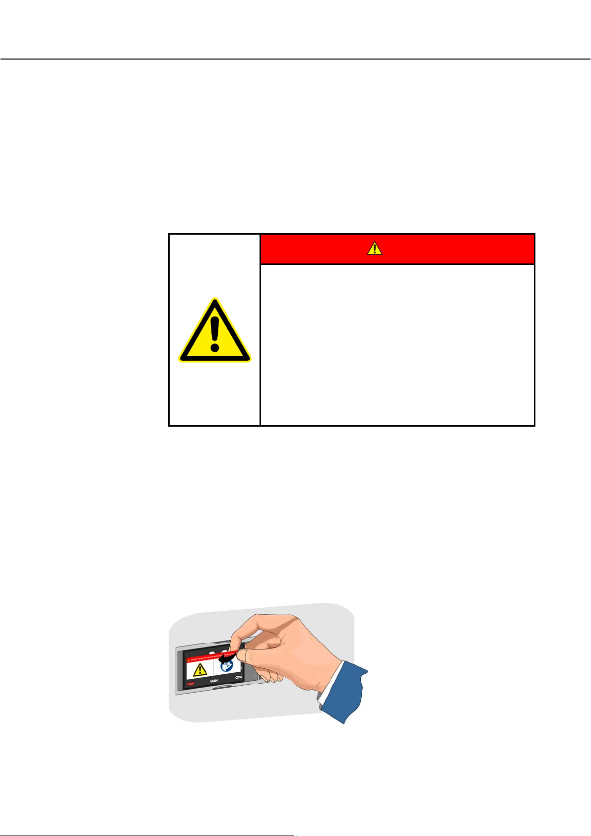
Pos: 41 /TD/Betrieb_Bedienung/Aufkleber vom TWB/ TWW abziehen - Grafik @ 37\mod_1362492020088_51.docx @ 214117 @ @ 1
Read the operating instructions of the over-temperature limiter with manual reset/with
automatic reset before starting the furnace. The safety sticker must be removed from the
over-temperature limiter with manual reset/with automatic reset. Any time a change is
made in the heat treatment program, the maximum permissible cut-off temperature (alarm
trigger temperature) at the over-temperature limiter with manual reset/with automatic reset
must be checked or re-entered.
We recommend setting the maximum setpoint temperature of the heating program in the
limiter between 5 °C and 30 °C, depending on the physical characteristics of the furnace,
below the trigger temperature of the over-temperature limiter with manual reset/with
automatic reset. This prevents an unwanted triggering of the over-temperature limiter with
manual reset/with automatic reset.
Description and function, see the
Operating Instructions of the overtemperature limit controller/guard
12
Fig. 7: Removing the sticker (similar to picture)
Page 13
Pos: 42 /TD/Einleitung/Produktbeschreibung/ Öfen/Überschrift - Entschlüsselung der Modellbez eichnung @ 2\mod_1184245078907_51.docx @ 19775 @ 3 @ 1
1.3.1 Key to the Model Names
Pos: 43 /TD/Einleitung/Produktbeschreibung/ Öfen/Entschlüssellung der Modellbezeichnung Ka mmerofen N 7/H - N 87/H (Modell 2015) @ 123\mod_1465208363287_51. docx @ 544390 @ @ 1
Example Explanation
N 41/H
N = Chamber furnace
N 41/H
7 = 9 liter furnace (volume in l)
11 = 11 liter furnace (volume in l)
17 = 17 liter furnace (volume in l)
25 = 25 liter furnace (volume in l)
31 = 31 liter furnace (volume in l)
41 = 41 liter furnace (volume in l)
61 = 61 liter furnace (volume in l)
87 = 87 liter furnace (volume in l)
N 41/HR
Pos: 44 /TD/Einleitung/Produktbeschreibung/ Öfen/Entschlüssellung der Modellbezeichnung N7/ H - N 87/H - Grafik @ 123\mod_1465210929875_51.docx @ 544572 @ @ 1
Pos: 45 /TD/Einleitung/Lieferumfang/Öfen/Über schrift - Lieferumfang @ 0\mod_1167822508130_51. docx @ 5112 @ 2 @ 1
13 = Tmax. 1300 °C (2372 F)
H = High temperature Tmax. 1280 °C (2336 F)
R = Increased power
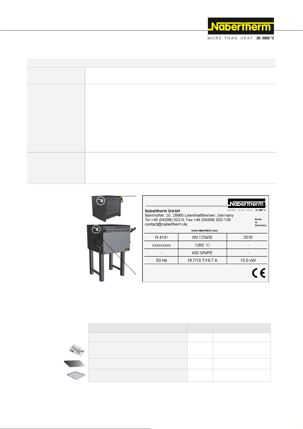
Fig. 8: Example model designation (type plate)
1.4 Scope of Delivery
Pos: 46 /TD/Einleitung/Lieferumfang/Öfen/Lief er umfang - Kammerofen N7/H - N 87/H (Modell 2015) @ 123\mod_146521 1806141_51.docx @ 544706 @ @ 1
The scope of delivery includes:
System components Quantity Comment
Chamber furnace 1 x Nabertherm GmbH
Power cable1) 1 x Nabertherm GmbH
SiC floor plate 1 x Nabertherm GmbH
Charging plate2) 1 x Nabertherm GmbH
13
Page 14
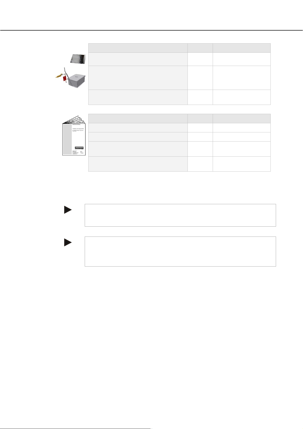
System components Quantity Comment
)
Annealing and hardening foil2)
4
Nabertherm GmbH
Protective gas box1) 1 x Nabertherm GmbH
Other components, variable depending on the
- - - See shipping documents
particular design
Document type Quantity Comment
Operating Instructions 1 x Nabertherm GmbH
Operating Manual for Controller 1 x Nabertherm GmbH
Pos: 47 /TD/Betrieb_Bedienung/Die mitgelieferte n Unterlagen beinhalten nicht zwangsläufig elektr ische Schaltpläne bzw. Pneuma ... @ 47\mod_13800280746 16_51.docx @ 247668 @ @ 1
Pos: 48 /TD/Einleitung/Technische Daten/Öfen/ Üb er schrift - Technische Daten - mit Hinweis @ 0\mod_116782 2840 737_51.docx @ 5121 @ 1 @ 1
Operating Instructions for
Protective Gas and Carburization Systems1)
Other documents, variable depending on the
1 x Nabertherm GmbH
1 x
particular design
1)
included with delivery depending on design/furnace model
2)
included with delivery if required, see shipping documents
3)
quantity depends on furnace model
4)
quantity as required, see shipping documents
Note
Store all documents carefully. All the functions of this furnace were tested during
manufacturing and prior to shipping.
Note
The documents included do not always contain the electrical schematics and pneumatic
schematics.
If you need the respective schematics they can be ordered from Nabertherm Service.
14
Page 15
2 Specifications
Electrical specifications are on the type plate located on the side of the furnace.
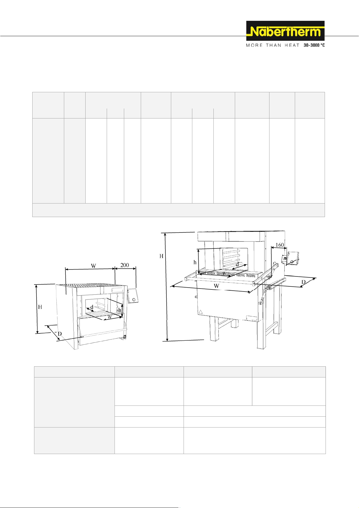
Pos: 49 /TD/Einleitung/Technische Daten/Öfen/ Mo de ll-Tabelle für Kammeröfen N 7/H - N 87/H (Modell 2015) @ 123\mod_1 465223703739_51.docx @ 545336 @ @ 1
Model Tmax Inner dimensions in
mm
°C w d h in l W D H in kW in kg
N 7/H1 1280 250 250 140 9 600 650 600 3,0 60 180
N 11/H1 1280 250 350 140 11 600 750 600 3,5 70 180
N 11/HR1 1280 250 350 140 11 600 750 600 5,5 70 120
N 17/HR1 1280 250 500 140 17 600 900 600 6,4 90 120
N 31/H 1280 350 350 250 31 880 1100 1340 15,0 210 105
N 41/H 1280 350 500 250 41 880 1250 1340 15,0 260 120
N 61/H 1280 350 750 250 61 880 1500 1340 20,0 400 120
Volume Outer dimensions in mm Heating
power
Weight Minutes
to Tmax2
N 87/H 1280 350 1000 250 87 880 1750 1340 25,0 480 120
1
table-top model
2
If connected at 230 V 1/N/PE rsp. 400 V 3/N/PE
Pos: 50 /TD/Einleitung/Technische Daten/Öfen/ Ma ß e des Ka mmerofens N 7/H - N 87/H (Modell 2015) - Grafik @ 123\mod_14652239 74241_51.docx @ 545362 @ @ 1
Fig. 9: Dimensions
Pos: 51 /TD/Einleitung/Technische Daten/Öfen/ Tabe lle Technische Daten für Ofenmodell Kammerofen N7/H - N 87/ H (Modell 2015) @ 123\mod_1465225518930_51.docx @ 54538 8 @ @ 1
Electrical connection 1-phase: 3-phase:
1
, N 17/HR1
Furnace model
N 7/H
N 11/H
N 11/HR
N 31/H, N 41/H
N 61/H, N 87/H
Thermal protection class
Voltage (V): See type plate on furnace
Frequency (Hz): See type plate on furnace
according to DIN EN 60519-2
Furnaces:
without safety controller: Class 0
with safety controller: Class 2
15
Page 16

Protection rating
Furnaces:
Protection type
Ambient conditions for
electrical equipment
Weights
Pos: 52 /TD/Einleitung/Technische Daten/Öfen/ Tabe lle Dauerschalldruckpegel < 80 dB(A) - 2 @ 1\mod_1170750 985 488_51.docx @ 8913 @ @ 1
Temperature: Humidity:
Furnace with accessories Varies (see shipping documents)
Emissions
Pos: 53 /TD/Einleitung/Technische Daten/Öfen/ Lege nde: 1Heizung nur zwischen zwei Phasen @ 77\mod_1415782894 129_51.docx @ 338720 @ @ 1
1
Heating only between two phases
Pos: 54 /TD/Einleitung/Gewährleistung_Haftu ng/ Überschrift - Gewährleistung und Haftung 1.1 @ 0\mod_11 67822979492_51.docx @ 5130 @ 2 @ 1
2.1 Warranty and Liability
Pos: 55 /TD/Einleitung/Gewährleistung_Haftung/ Öfen und Schaltanlagen - Gewährleistung und Haftung @ 0\ m od_1 157536440972_51.docx @ 1569 @ @ 1
As regards warranty and liability, the normal Nabertherm warranty terms apply,
unless individual terms and conditions have been agreed. However, the following
conditions also apply:
Warranty and liability claims for personal injury or damage to property shall be excluded if
they are attributable to one or more of the following causes:
Everyone involved in operation, installation, maintenance, or repair of the furnace
must have read and understood the operating instructions. No liability will be accepted
for damage or disruptions to operation resulting from non-compliance with the
operating instructions.
Not using the furnace as intended,
Improper installation, start-up, operation, or maintenance of the furnace,
Operation of the furnace with defective safety equipment or improperly installed or
non-functioning safety and protective equipment,
Not observing the references in the operating instructions to transportation, storage,
installation, start-up, operation, maintenance, or equipping the furnace,
Making unauthorized changes to the furnace,
Making unauthorized changes to the operating parameters,
Making unauthorized changes to the parameterization, the settings, or the program,
Original parts and accessories are designed especially for Nabertherm furnaces.
Replace parts only with original Nabertherm parts. Otherwise the warranty will be
void. Nabertherm accepts absolutely no liability for damage caused by using parts that
are not original Nabertherm parts.
Catastrophes due to third-party causes and force majeure.
Pos: 56 /TD/Sicherheit/Überschrift - Sicher heit @ 0\mod_1158843961540_51.docx @ 3103 @ 1 @ 1
§
1
IP20
+5 °C to + +40 °C
max. 80% non-condensing
Continuous sound pressure
level:
< 80 dB(A)
3 Safety
Pos: 57 /TD/Sicherheit/Überschrift - Bestimmung sge mäße Verwendung @ 0\mod_1167823503921_51.docx @ 5148 @ 2 @ 1
3.1 Intended Use
Pos: 58 /TD/Sicherheit/Bestimmungsgemäße Verwendun g allgemeiner Ofen-Anlagen_Materialien - Teil 1 @ 24\ mod_1337938775936_51.docx @ 161920 @ @ 1
Safety
Pos: 59 /TD/Sicherheit/Bestimmungsgemäße Verwendun g Kammeröfen - N 7/H - N87/H (Dental_Labor_Thermprozess) @ 123\ mod_1465289960174_51.docx @ 545650 @ @ 1
16
The Nabertherm furnace was designed and built in conformance with a careful selection of
the applicable harmonized standards and other technical specifications. Hence, it
corresponds to the state of the art and assures the greatest degree of safety.
Only materials whose characteristics and melting temperatures are known may be heated.
Consult any available safety-related material data sheets.
These universal chamber furnaces with radiation heating are designed for tough heat
treatment applications. They are perfect for processes in toolmaking and in the hardening
Page 17
Pos: 60 /TD/Sicherheit/Von den im Ofen eingesetzten Mater ialien bzw. Ausgasungen können sich unter Umständen Sc hadstoffe .. @ 45\mod_1377243392217_51.docx @ 242065 @ @ 1
Pos: 61 /TD/Sicherheit/Es dürfen nur die Materialien ein gesetzt werden, deren Eigenschaften und Schmelzte mperaturen ... @ 49\mod_1385394498752_51.docx @ 254350 @ @ 1
Pos: 62 /TD/Sicherheit/Eine andere oder darüber hinausg ehende Benutzung, wie z.B. die Verarbeitung ... @ 45\mod_1377242071687_51.docx @ 242040 @ @ 1
Safety
Pos: 63 /TD/Sicherheit/Bei Öfen mit Temperaturwählbegrenzer muss die Abschalttemperatur so eingestellt werden ... @ 45\mod_1377244417122_51.docx @ 242390 @ @ 1
Pos: 64 /TD/Sicherheit/Veränderungen am Ofen, müssen mit Nabertherm schriftlich abgestimmt werden ... @ 45\mod_1377243398694_51. docx @ 242240 @ @ 1
Pos: 65 /TD/Sicherheit/Die Aufstellhinweise und Si cherheitsbestimmungen sind einzuhalten, ander nfalls gilt der Ofen als ... @ 45\mod_1377243410507_51.docx @ 242265 @ @ 1
Pos: 66 /TD/Sicherheit/Das Öffnen des Ofens im heißen Zusta nd über 200 °C (392 °F) kann zu einem erhöhtem Verschleiß ... @ 39\mod_1364289911635_51.docx @ 219945 @ @ 1
Pos: 67 /TD/Sicherheit/Der Betrieb mit Kraftquel len, Produkten, Betriebsmitteln, Hilfsstoffen us w., ... @ 45\mod_1377241083975_51.docx @ 241990 @ @ 1
Pos: 68 /TD/Allgemeine Hinweise (für alle Anleitungen) /Hinweis - Dieser Ofen ist für die gewerbliche Anwendung ... Der Ofen ist nicht für die Erwärmung ... @ 19\mod_1315980979500_51.docx @ 134548 @ @ 1
shop, such as annealing, hardening and forging. A wide variety of accessories enables these
furnaces to be tailored to the relevant application.
Under certain circumstances gases or materials may be released from the materials in
the furnaces that settle on the insulation or the heating elements and destroy them. If
applicable, read the labels and instructions on the packaging of materials that
you use.
Only materials whose characteristics and melting temperatures are known may be
heated. Consult any available safety data sheets of the materials. Any other use
beyond this is improper, including the processing of products other than those for
which the furnace was intended as well as handling hazardous materials or materials
dangerous to health, and must be approved in writing by the manufacturer Nabertherm
GmbH.
Any other use, such as processing of products other than those for which the furnace
was intended as well as handling hazardous materials or materials dangerous to health
is deemed IMPROPER and such uses must be approved in writing by Nabertherm.
Furnaces with over-temperature limit controllers must have their shut-down
temperatures set to prevent any overheating of the material.
The set-up instructions and safety regulations must be followed, otherwise the furnace
will be considered improperly used, effectively cancelling any claims against
Nabertherm GmbH. The EC Declaration of Conformity will cease to be valid if any
modifications are made to the machine without our approval.
The set-up instructions and safety regulations must be followed, otherwise the furnace
will be considered improperly used, effectively cancelling any claims against
Nabertherm GmbH.
Opening the furnace while it is still hot, over 200 °C (392 °F), can lead to increased
wear of the following components: insulation, door seal, heating elements and furnace
housing. No liability shall be accepted for any damage to the goods or the furnace
resulting from non-compliance with this warning.
Operation with power sources, products, operating equipment, auxiliary materials, etc.,
which are listed as hazardous or which may in any way harm the health of the operator is
prohibited.
The furnace must not be filled with materials or substances that release explosive gases or
vapors. Only materials and substances whose properties are known may be used.
- This furnace was designed for commercial use. The furnace is not designed
for heating food, animals, wood, grain, etc.
- The furnace must not be used to heat the workplace.
- Do not use the furnace to melt ice or for similar purposes.
- Do not use the furnace as a clothes dryer.
Caution
Applicable safety instructions are contained in individual chapters.
17
Page 18
Pos: 69 /TD/Sicherheit/Überschrift - Für hier aus r esultierende Schäden haftet der Betreiber @ 10\mod_125673 1411117_51.docx @ 68223 @ @ 1
Pos: 70 /TD/Allgemeine Hinweise (für alle Anleitungen) /Hinweis - Dieser Ofen verfügt über keine Sicherhei t stechnik für Prozesse, ..-nicht brennbare Gase @ 8\ mo d_12 35038699771_51.docx @ 51483 @ @ 1
Pos: 71 /TD/Allgemeine Hinweise (für alle Anleitungen) /Hinweis - Dieses Produkt entspricht nicht der ATEX- Richtlinie und darf nicht ..-nicht brennbare Gase @ 2\ mod_1184228756893_51.docx @ 19686 @ @ 1
The operator is liable for any resulting damages.
Caution
Operating the furnace with explosive gases or mixtures, including explosive gases or
mixtures created as a result of heating/drying, is prohibited.
This furnace features no safety technology for processes which produce combustible
mixtures, for example debinding.
If the furnace is still used for such processes despite this fact, the concentration of organic
gas mixtures in the furnace must never exceed 3% of the lower explosion limit (LEL). This
pre-requisite applies not only to normal operation but, in particular, to exceptional
situations such as process disruptions (caused, for example, by the failure of a power unit).
You must ensure that the furnace is adequately ventilated and vented.
Nabertherm offers a broad range of furnaces which were especially developed for processes
involving the use of combustible gas mixtures.
Note
This product does not comply with the ATEX Directive and may not be used in ignitable
atmospheres. It must not be operated with explosive gases or mixtures or during processes
where explosive gases or mixtures are produced.
Pos: 72 /TD/Sicherheit/Überschrift - Anfor derungen an den Betreiber der Anlage @ 0\mod_1167823775531_51.doc x @ 5157 @ 2 @ 1
3.2 Requirements for the Furnace Operator
Pos: 73 /TD/Sicherheit/Anforderungen an den Betreiber der Anlage - RHTH, RHTC, LHT, RT - Rohröfen @ 2\mod_1184570280797 _51.docx @ 19913 @ @ 1
The set-up instructions and safety regulations must be followed, otherwise the furnace will
be deemed to have been used improperly, effectively cancelling any claims against
Nabertherm GmbH.
This level of safety when operating the furnace can be achieved only if all the necessary
measures have been taken. It depends on the furnace operator's diligence in planning these
measures and controlling how they are carried out.
The operator must ensure that
all harmful gases are removed from the workplace, for example by an extraction
system,
the extraction system is switched on,
the workplace is properly ventilated,
the furnace is operated only in a perfect operating condition and, in particular, that the
functions of the safety components are checked regularly.
the required personal protective equipment is available for and used by the operating,
maintenance, and repair personnel.
these operating instructions, including the supplier documentation, are kept near the
furnace. These instructions must be available at all times for anyone working with or
on the furnace;
all the safety and operating instruction signs on the furnace can be read properly.
Damaged or unreadable signs must be replaced immediately,
furnace personnel are informed regularly about all issues involving occupational
safety and environmental protection and are familiar with all the operating
instructions, especially those involving safety,
a risk assessment is carried out (in Germany, covered of the Occupational Safety Act)
to determine any other hazards that may result from the working conditions particular
to the furnace's location,
18
Page 19
Pos: 74 /TD/Sicherheit/Anforderungen an den Betreiber der Anlage - Betrieb des Ofens @ 30\mod_1349086871519_51. doc x @ 184910 @ @ 1
Pos: 75 /TD/Allgemeine Hinweise (für alle Anleitungen) /Hinweis - Bei Verwendung von Begasungskästen wird ei ne A r beitstemperatur bis zu 1100 °C (2012 °F)... @ 123\mod_14 6529 0938112_51.docx @ 545676 @ @ 1
all other instructions and safety guidelines that have been determined in a risk
assessment for the workplace are compiled in an operation manual (in Germany,
covered of the Ordinance Regulating the Use of Operating Equipment).
Only sufficiently qualified and authorized personnel may operate, maintain and repair
the system. This personnel must be trained in how to operate the furnace and must
confirm their participation in the training with a personal signature. The training
program must be documented in detail. In case an operator is replaced, additional
training must also take place. The additional training may only be performed by
authorized, trained individuals familiar with the system. The additional training must
be painstakingly documented and participation must be evidenced by the names and
signatures of the participating employees.
Operating the Furnace
Operating the furnace with explosive gases or mixtures, i.e., including any explosive
gases or mixtures created as a result of heating/drying, is prohibited.
A furnace opened while still hot radiates enormous heat energy, which can cause
burns.
Working with the furnace, for example opening the furnace door, etc., is only
permissible when the whole space needed for the door to swing out, the danger zone,
is visible to the operator.
When working at the furnace with high temperatures, the appropriate protective
clothing and protective goggles must be worn.
Danger! Risk of burns:
Several spots on the housing and components of the control box can become hot
enough during normal operation to cause skin burns.
When the vent supports are hot, touching them will lead to burns.
Note
If the protective gas boxes are used, a working temperature to 1100 °C (2012 °F) is
recommended; with working temperatures to 1150 °C (2102 °F) the boxes will suffer
increased wear.
Pos: 76 /TD/Allgemeine Hinweise (für alle Anleitungen) /Hinweis - In Deutschland ist die allgemeine Unfa ll ver hütungsvorschrift zu beachten. @ 3\mod_1193667 801739_51.docx @ 26122 @ @ 1
a
Note
In Germany, the general accident protection guidelines must be observed. The national
accident prevention regulations of the country of operation apply.
Pos: 77 /TD/Sicherheit/Überschrift - Anfor derungen an das Bedienpersonal @ 0\mod_1167825643423_51.doc x @ 5166 @ 2 @ 1
3.3 Requirements for the Operating Personnel
Pos: 78 /TD/Sicherheit/Anforderungen an das Bedienper s onal @ 0\mod_1158218663482_51.docx @ 2155 @ @ 1
Everyone involved in operation, installation, maintenance, or repair of the furnace must
have read and understood the operating instructions. No liability will be accepted for
damage or disruptions to operation resulting from non-compliance with the operating
instructions.
Only adequately qualified and authorized persons may operate, maintain, or repair the
furnace.
Operating personnel are instructed regularly in all aspects of occupational safety and
environmental protection and are familiar with all the operating instructions, in particular,
safety instructions.
Only trained personnel may operate the control and safety equipment.
The operator should complete these details:
Operator
19
Page 20
Pos: 79 /TD/Sicherheit/Sicherheitssymbole/W arnhinweise-ISO-ANSI/Warnsymbol_Gefahr - Absicherung von Gefahren bei Übertemperatur am TWB- TWW @ 37\mod_1362490404893_51.docx @ 214067 @ @ 1
_______________________________________________________________
The furnace may only be transported by
_______________________________________________________________
The furnace may only be installed by
_______________________________________________________________
The furnace may only be commissioned by
_______________________________________________________________
Initial instructions may only be given by
_______________________________________________________________
Malfunctions may only be rectified by
_______________________________________________________________
The furnace may only be maintained by
_______________________________________________________________
The furnace may only be cleaned by
_______________________________________________________________
The furnace may only be serviced by
_______________________________________________________________
The furnace may only be repaired by
_______________________________________________________________
The furnace may only be shut down by
_______________________________________________________________
Pos: 80 /TD/Sicherheit/Überschrift - Schutzklei du ng @ 0\mod_1167825795750_51.docx @ 5175 @ 2 @ 1
3.4 Protective Clothing
Pos: 81 /TD/Sicherheit/Schutzkleidung -Gesichts schutz-Handschuhe-Stiefel @ 5\mod_12113759853 20_51.docx @ 37168 @ @ 1
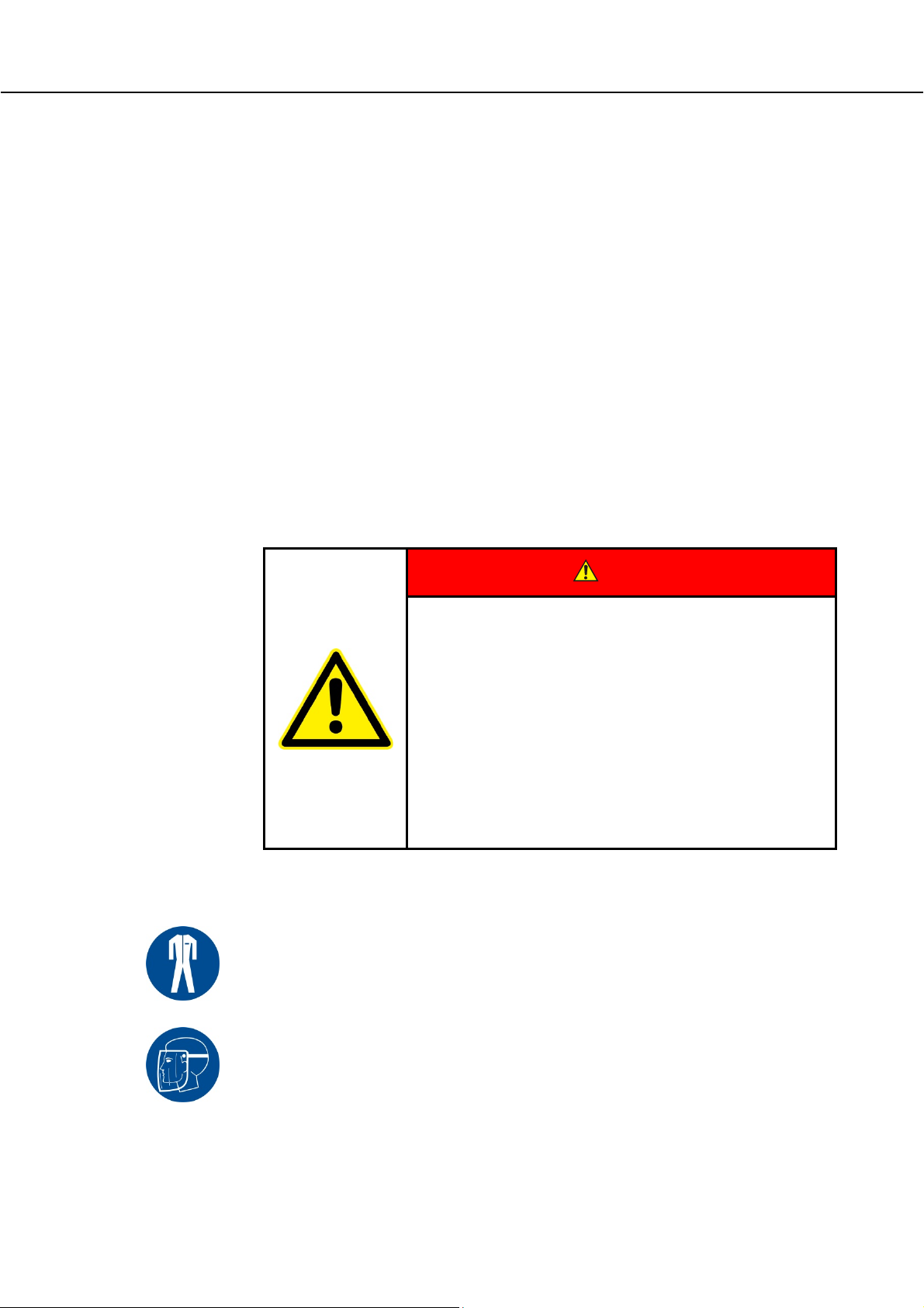
When close to furnaces, heat treatment accessories and similar components, wear protective
clothing that is resistant to heat and splashes of quenching media.
Wear a full-face mask that is resistant to heat and splashes of quenching media.
DANGER
• Danger caused by incorrectly entered cut-off
temperature at the over-temperature limiter with
manual reset/over-temperature limiter with automatic
reset.
• Mortal danger
• If, as a result of over-temperature from the charge and/or the
operating equipment, a charge is likely to be damaged at this preset cut-off temperature of the over-temperature limiter with
manual reset/over-temperature limiter with automatic reset, or if
the charge itself becomes a source of danger for the furnace or its
surroundings, the cut-off temperature must be reduced at the
over-temperature limiter with manual reset/automatic reset to the
maximum permissible value.
20
Page 21
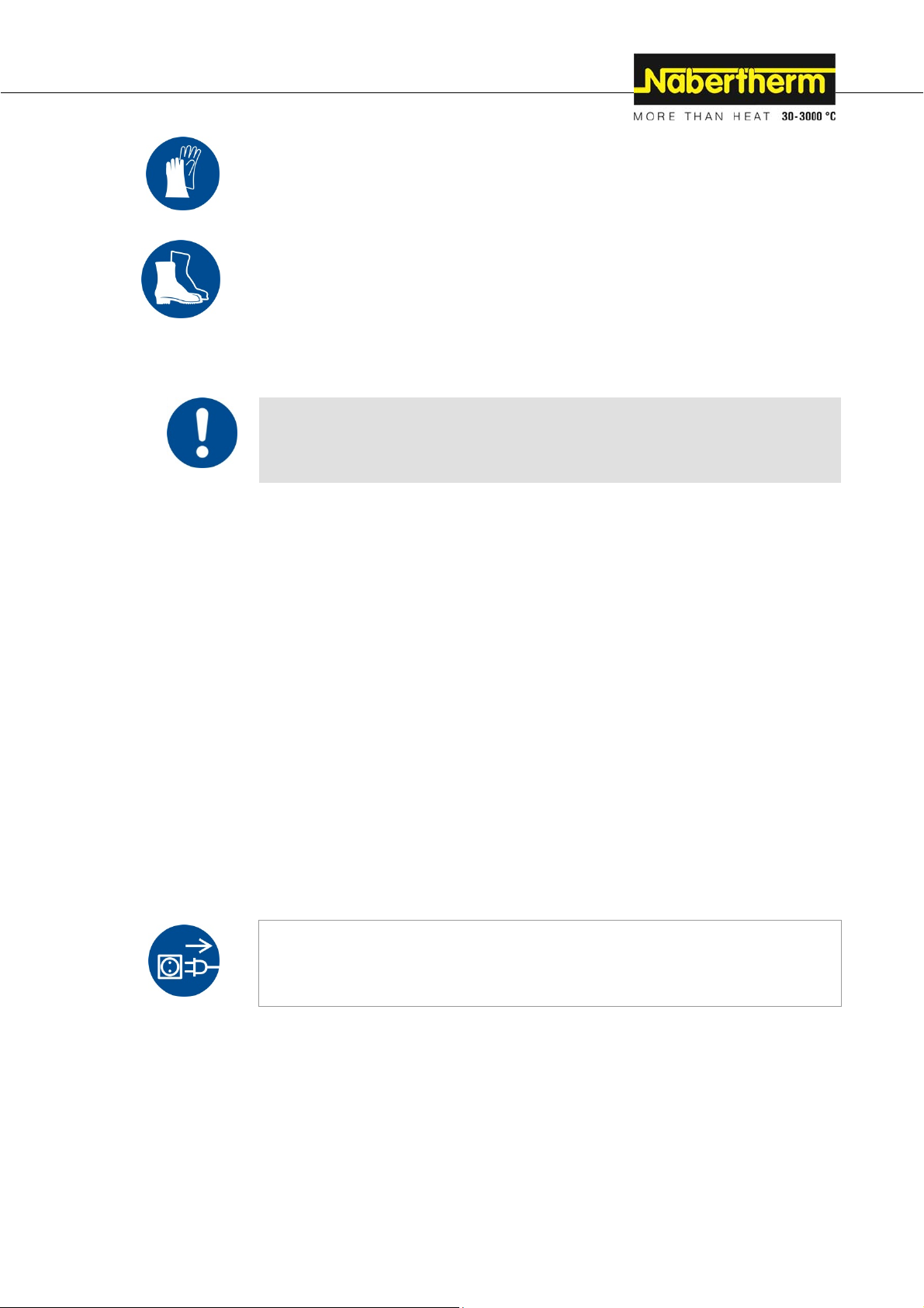
Protect your hands when handling heat treatment accessories and similar components by
wearing heat-resistant gloves.
Protect your hands when cutting annealing and hardening foil/annealing envelopes by
wearing firm gloves.
Wear safety boots to protect your feet.
Pos: 82 /TD/Sicherheit/Überschrift - Grundlegende Maßnahmen bei Normalbetrieb @ 0\mod_1167825919827_51. docx @ 5184 @ 2 @ 1
3.5 Basic Measures During Normal Operation
Pos: 83 /TD/Sicherheit/Grundlegende Maßnahmen bei Norm al betrieb (LHT ../..-Tischmodell) @ 32\mod_1352295191692_51.docx @ 191520 @ @ 1
Risks during Normal Operation!
Before switching the furnace on, check and ensure that only authorized persons are in the
working area of the furnace and that no one can be injured as a result of operating the
furnace.
Before starting production each time, check and ensure that all the safety equipment works
properly.
Before starting production each time, check the furnace for obvious damage and ensure that
it is operated only in a perfect condition. Report any defects to a supervisor immediately.
Before starting production each time, remove all materials and objects that are not needed
for production from the working area.
At least once every day (see also Servicing and Maintenance) check the following:
Check the furnace for obvious external damage,
Check all hydraulic or pneumatic hoses, make sure that they are not leaking and that
they are connected properly (if applicable),
Check all gas and oil lines, make sure that they are not leaking and that they are
connected properly (if applicable),
Check that the fan works properly (if applicable)
Pos: 84 /TD/Sicherheit/Überschrift - Grundlegende Maßnahmen im Notfall @ 1\mod_1170943369267_51.doc x @ 9093 @ 2 @ 1
3.6 Basic Measures in Case of Emergency
Pos: 85 /TD/Sicherheit/Überschrift - Verhalten im No tf al l @ 1\mod_1170949904855_51.docx @ 9123 @ 3 @ 1
3.6.1 What to do in an Emergency
Pos: 86 /TD/Allgemeine Hinweise (für alle Anleitungen) /Überschrift - Öfen mit Netzstecker (Einzug links) @ 7\mod_1232450264630_51.docx @ 48098 @ @ 1
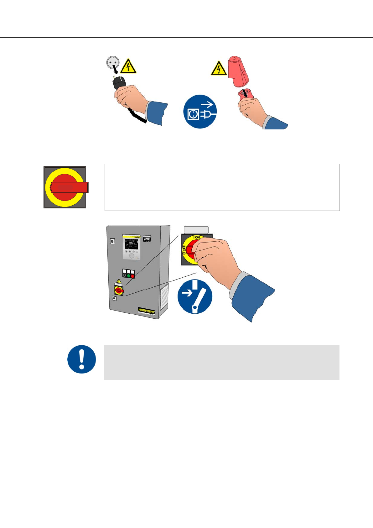
Furnaces with power plug
Pos: 87 /TD/Allgemeine Hinweise (für alle Anleitungen) /Hinweis - Das Stillsetzen im Notfall ist vorgeseh en durch Ziehen des Netzsteckers. @ 6\mod_1222062836860 _51.docx @ 42829 @ @ 1
Note
The power plug is to be pulled out to stop the furnace in case of an emergency.
Therefore, the power plug must be accessible at all times when the furnace is operating so
that it can be pulled out quickly in case of an emergency.
21
Page 22
Pos: 88 /TD/Sicherheit/Grundlegende Maßnahmen im Notf a ll - Netzstecker ziehen (alle Anleitungen) - Graf ik @ 36\mod_1360079722854_51.docx @ 208920 @ @ 1
Fig. 10: Pull the power plug (similar to picture)
Pos: 89 /TD/Allgemeine Hinweise (für alle Anleitungen) /Überschrift - Öfen mit Hauptschalter (Einzug li nks) @ 7\mod_1232450214124_51.docx @ 48083 @ @ 1
Furnaces with main switch
Pos: 90 /TD/Allgemeine Hinweise (für alle Anleitungen) /Hinweis - Schalten Sie im Notfall sofort den Ofen am Haup tsc halter (Stellung „O“) spannungsfrei @ 2\mod_1184230 771480_51.docx @ 19710 @ @ 1
I ON
Note
In an emergency, immediately switch off the voltage supply to the furnace at the main
O OFF
switch (position "O/OFF"). Wait until the furnace chamber and attaching parts have cooled
to room temperature.
Pos: 91 /TD/Sicherheit/Grundlegende Maßnahmen im Notf a ll - Anlage über den Hauptschalter ... (alle Anleitungen) - Grafik @ 121\mod_1463732481989_51.docx @ 475758 @ @ 1
Pos: 92 /TD/Allgemeine Hinweise (für alle Anleitungen) /Warnung - Bei unerwarteten Vorgängen im Ofen (z.B. star ke Rauchentwicklung oder Geruchsbelästigung) @ 4\mod_ 1205 306579737_51.docx @ 34218 @ @ 1
22
Fig. 11: Disconnect power to the system using the main switch (similar to picture)
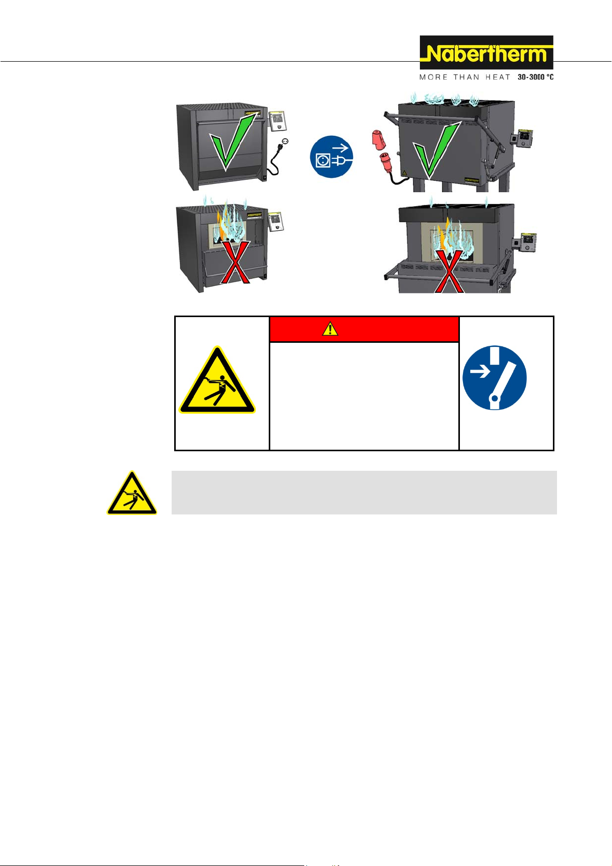
Risks during Normal Operation!
Switch the furnace off immediately in case of unexpected occurrences in the furnace (e.g. a
lot of smoke or unusual smells). Wait until the furnace has cooled naturally to room
temperature.
Page 23
Pos: 93 /TD/Allgemeine Hinweise (für alle Anleitungen) /Warnung - Bei unerwarteten Vorgängen darf der Ofen nic ht geöffnet werden - Grafik N 7/H - N 87/H @ 123\mod_1465292169374_51. d ocx @ 545702 @ @ 1
In case of a fire, keep
the door closed. This
will allow you to
prevent the spread of
smoke and keep out a
supply of oxygen.
Pos: 94 /TD/Sicherheit/Sicherheitssymbole/W arnhinweise-ISO-ANSI/Warnsymbol_Gefahr - Elektrischer Schlag - Piktogramm elektr. Schlag- Fr eischalten @ 11\mod_1263372988761_51.docx @ 70523 @ @ 1
DANGER
• Danger from electric shock.
• Danger to life.
• Work on the electrical
equipment may be performed
only by qualified electricians
or by technicians authorized
by Nabertherm.
• Disconnect the furnace
Pos: 95 /TD/Allgemeine Hinweise (für alle Anleitungen) /Warnung - Arbeiten an der elektrischen Ausrüstung dür f en nur von ... @ 2\mod_1184228021019_51.docx @ 19673 @ @ 1
Warning - Danger of Electric Shock!
Work on the electrical equipment may be done only by qualified, authorized electricians.
Pos: 96 /TD/Sicherheit/Überschrift - Grundlegende Maßnahmen bei Wartung und Instandhaltung @ 0\mod_11678260 60620_51.docx @ 5193 @ 2 @ 1
3.7 Basic Measures for Servicing and Maintenance
Pos: 97 /TD/Sicherheit/Grundlegende Maßnahmen bei W artung und Instandhaltung @ 0\mod_1158222458436_51.doc x @ 2188 @ @ 1
Maintenance work must be performed by authorized persons following the maintenance
instructions and the accident prevention regulations. We recommend that the maintenance
and repair work be carried out by the service team of Nabertherm GmbH. Non-compliance
may cause injuries, death, or considerable damage to property.
Switch off the furnace and make sure it cannot be switched on again inadvertently (lock the
main switch and secure it with a padlock), or pull out the power plug.
Clear an adequate area around the furnace to facilitate the repair work.
Suspended loads are dangerous. Working beneath a suspended load is prohibited. There is a
risk of fatal injury.
Relieve the pressure on hydraulic or pneumatic equipment before carrying out maintenance
or repair work (if applicable).
When cleaning furnaces, control cabinets, or electrical equipment housings, never spray
them with water.
When maintenance or repair work has been completed, before recommencing production
ensure the following:
Check that loosened screw connections have been re-tightened,
23
Page 24

Reinstall protective equipment, screens, and filters,
Remove all material, tools, and other equipment used for the maintenance or repair
work from the working area of the furnace,
Remove any liquids that have leaked,
Check that all safety functions (e.g. emergency stop button) work properly,
Pos: 98 /TD/Sicherheit/Überschrift - Umweltschutz vorschriften @ 0\mod_1167826189237_51.doc x @ 5202 @ 2 @ 1
Power cables may be replaced only with similar, approved cables.
3.8 Environmental Regulations
Pos: 99 /TD/Sicherheit/Umweltschutzvorschr iften Schmierfette-Hydrauliköl-Kühlmitte l @ 0\ mod_1158223424304_51.docx @ 2199 @ @ 1
All statutory duties regarding waste avoidance, proper recycling, and disposal must be
observed when work is carried out on and with the furnace.
Problem materials that are no longer needed, such as lubricants or batteries, must not be
placed in normal waste disposal systems or allowed to enter the sewage system.
During installation, repair, and maintenance work, substances that are hazardous to water,
such as
lubricating grease and oils
hydraulic oils
refrigerants
solvent-based cleaning fluids must not be allowed to contaminate the soil or enter the
sewage system.
These substances must be stored, transported, collected, and disposed of in suitable
containers.
Note
The operator must ensure that national environmental regulations are observed.
Pos: 100 /TD/Sicherheit/Umweltschutzvorschr iften Elektronische Bauteile-Isolierung-A l tmetall @ 4\mod_1205143314853_51.docx @ 32563 @ @ 1
When it is delivered, this furnace contains no substances that make a hazardous waste
classification necessary. However, residues of process materials may accumulate in the
furnace insulation during operation. These may be hazardous to health and/or the
environment.
Dismantle the electronic components and dispose of them as electric scrap.
Remove the insulation and dispose of it as hazardous waste (See Servicing, Cleaning,
and Maintenance with Ceramic Fiber Material)
Dispose of the housing as scrap metal.
Pos: 101 /TD/Sicherheit/Sicherheitssymbole/W arnhinweise-ISO-ANSI/Erläuterung ANSI Z535.6 @ 8\ mod_1243323558881_51.docx @ 57444 @ 2 @ 1
3.9 Explanation of the Symbols and Warnings
Note
In the following operating instructions, specific warnings are given to draw attention to
residual risks that cannot be avoided when the furnace is operating. These residual risks
include dangers for humans/products/ the furnace, and the environment.
The symbols used in the operating instructions are especially intended to draw attention to
safety information.
The symbols used cannot replace the text of the safety information. Therefore, always read
the entire text.
Graphic symbols correspond to ISO 3864. In accordance with the American National
Standard Institute (ANSI) Z535.6 the following warning information and words are used in
this document:
24
Page 25
The general hazard symbol, in combination with the words CAUTION, WARNING and
DANGER warns about the risk of serious injury. Observe the following information to
prevent injury or death.
NOTICE
Refers to a hazard that could damage or destroy the equipment.
CAUTION
Refers to a hazard with a minor or medium risk of injury.
WARNING
Refers to a hazard that could cause death, serious or irreversible injury.
DANGER
Refers to a hazard that could directly cause death, serious or irreversible injury.
25
Page 26
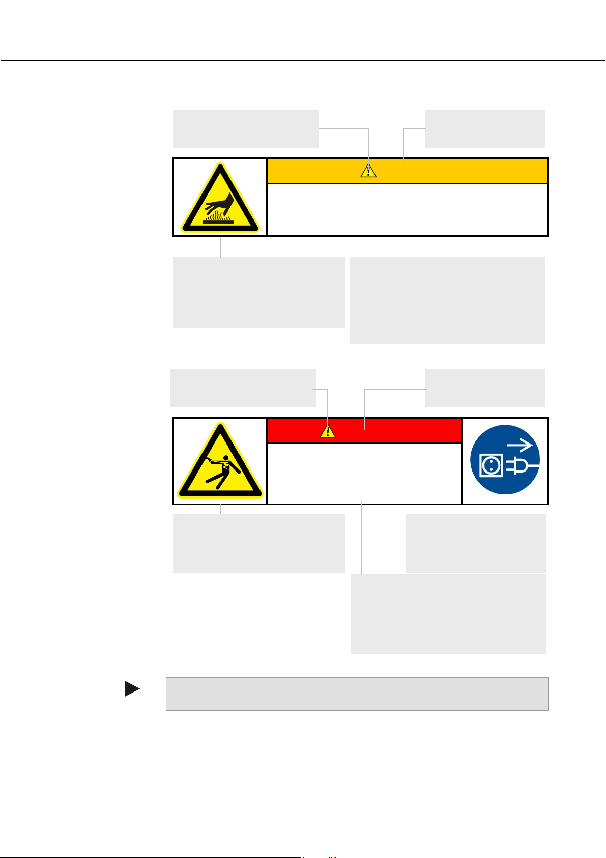
Structure of the Warning: All Warnings are Structured as Follows
Hazard symbol
Indicates the risk of injury
Signal word
Classifies the danger
WARNING
• Type and source of the danger
• Consequences of non-compliance
• Action to prevent danger
Graphical symbols (optional)
according to ISO 3864:
Consequences, measures, and
prohibitions
Reference texts:
• Type and source of the danger
• Possible consequences of noncompliance
• Measures/Prohibitions
or
Hazard symbol
Indicates the risk of injury
Signal word
Classifies the danger
Pos: 102 /TD/Sicherheit/Sicherheitssymbole/W arnhinweise-ISO-ANSI/Überschrift - Hinweis sy mbole in der Anleitung @ 9\mod_1247053429626_51.doc x @ 62751 @ @ 1
Pos: 103 /TD/Sicherheit/Sicherheitssymbole/W arnhinweise-ISO-ANSI/Hinweis - Unter diesem Sy mb ol er halten Sie Anweisungshinweise und ... @ 9\mod_1247053932311_51.docx @ 62785 @ @ 1
DANGER
• Type and source of the danger
• Consequences of non-compliance
• Action to prevent danger
Graphical symbols (optional)
according to ISO 3864:
Consequences, measures, and
prohibitions
Graphical symbols
(optional) according to ISO
3864:
Instructions or prohibitions
Reference texts:
• Type and source of the danger
• Possible consequences of noncompliance
• Measures/prohibitions
Information Symbols in the Instructions:
Note
Below this symbol you will find instructions and particularly useful information.
26
Page 27
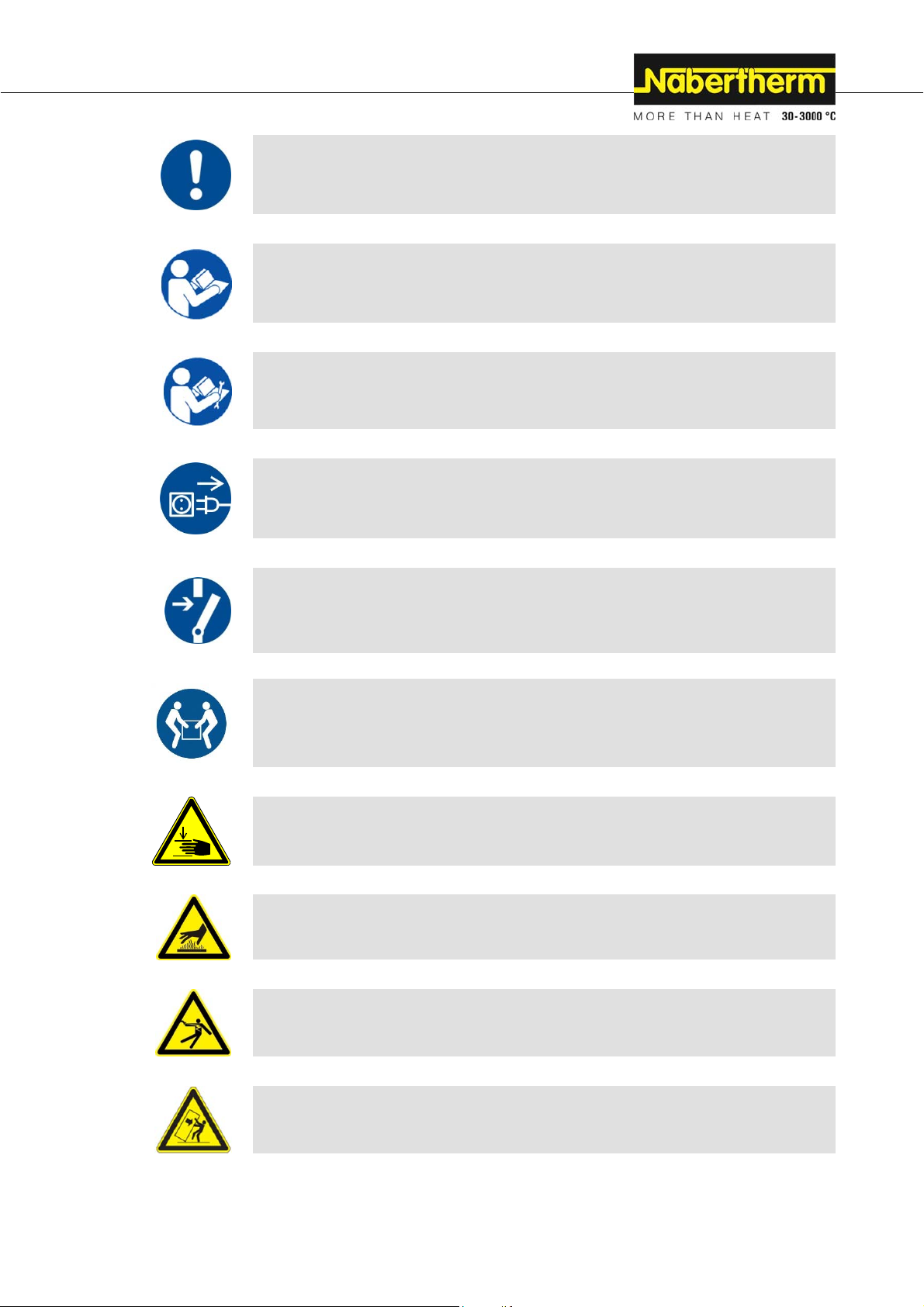
Pos: 104 /TD/Sicherheit/Sicherheitssymbole/W arnhinweise-ISO-ANSI/Piktogramm in der Anleit ung - Gebot - Gebotszeichen - Wichtige Gebote sind zu befo lgen @ 9\ mod_1247056175982_51.docx @ 62853 @ @ 1
Pos: 105 /TD/Sicherheit/Sicherheitssymbole/W arnhinweise-ISO-ANSI/Piktogramm in der Anleit ung - Gebot - Wichtige Information für den Bediener @ 9\mod_124 7053200729_51.docx @ 62717 @ @ 1
Pos: 106 /TD/Sicherheit/Sicherheitssymbole/W arnhinweise-ISO-ANSI/Piktogramm in der Anleit ung - Gebot - Wichtige Information für das Wartungsperson al @ 9\mod_1247053206042_51.docx @ 62734 @ @ 1
Pos: 107 /TD/Sicherheit/Sicherheitssymbole/W arnhinweise-ISO-ANSI/Piktogramm in der Anleit ung - Gebot - Netzstecker ziehen @ 9\mod_1247055471526_5 1. docx @ 62836 @ @ 1
Rule - Rule Sign
This symbol draws attention to important rules that must be followed. Rule signs protect
people against injury and show what is to be done in certain situations.
Rule - Important Information for Operators
This symbol draws the operator's attention to important information and operating
instructions that must be followed.
Rule - Important Information for Maintenance Personnel
This symbol draws the maintenance personnel's attention to important operating and
maintenance instructions (service) that must be followed.
Rule - Pull Out the Power Plug
This symbol tells the operator to pull out the power plug.
Pos: 108 /TD/Sicherheit/Sicherheitssymbole/W arnhinweise-ISO-ANSI/Piktogramm in der Anleit ung - Gebot - Anlage spannungsfrei schalten @ 11\mod_1263 373877432_51.docx @ 70540 @ @ 1
Pos: 109 /TD/Sicherheit/Sicherheitssymbole/W arnhinweise-ISO-ANSI/Piktogramm in der Anleit ung - Gebot - Anheben mit mehreren Personen @ 9\mod_1247063058 002_51.docx @ 62938 @ @ 1
Pos: 110 /TD/Sicherheit/Sicherheitssymbole/W arnhinweise-ISO-ANSI/Piktogramm in der Anleit ung - Warnung - Quetschgefahr @ 10\mod_1256733173584_51. docx @ 68239 @ @ 1
Pos: 111 /TD/Sicherheit/Sicherheitssymbole/W arnhinweise-ISO-ANSI/Piktogramm in der Anleit ung - Warnung - Heiße Oberfläche - Oberfläche nicht berühr en @ 9\mod_1247054774780_51.docx @ 62802 @ @ 1
Pos: 112 /TD/Sicherheit/Sicherheitssymbole/W arnhinweise-ISO-ANSI/Piktogramm in der Anleit ung - Warnung - elektrischer Schlag - zur Vermeidung Anweisu ng folgen @ 9\mod_1247055093892_51.docx @ 62819 @ @ 1
Pos: 113 /TD/Sicherheit/Sicherheitssymbole/W arnhinweise-ISO-ANSI/Piktogramm in der Anleit ung - Warnung - Umkippen des Gerätes @ 9\mod_1247059198372_ 51.docx @ 62870 @ @ 1
Mandatory rule - Disconnect the furnace
This symbol informs the operator that before beginning any work the furnace must be
disconnected from the power supply and the applicable safety rules and accident prevention
regulations must be observed.
Rule - Lift only with Several People
This symbol draws the personnel's attention to the fact that this device may only be lifted
and moved to its final destination by several people.
Caution – Fingers or Hands May Be Crushed
This symbol warns the operator of the potential for fingers or hands to be crushed. Ignoring
this can lead to injury.
Warning - Hot Surface, Do Not Touch
This symbol warns the operator that the surface is hot and should not be touched.
Warning - Danger of Electric Shock
This symbol warns the operator that there is a risk of an electric shock if the following
warnings are not heeded.
Warning – Risk of Device Toppling Over
This symbol tells the operator that there is a risk of the device toppling over if the following
warnings are not heeded.
27
Page 28

Pos: 114 /TD/Sicherheit/Sicherheitssymbole/W arnhinweise-ISO-ANSI/Piktogramm in der Anleit ung - Warnung - Schwebende Lasten @ 9\mod_1251450500309_51.doc x @ 65454 @ @ 1
Pos: 115 /TD/Sicherheit/Sicherheitssymbole/W arnhinweise-ISO-ANSI/Piktogramm in der Anleit ung - Warnung - Heben schwerer Lasten @ 9\mod_1247059891358_5 1.docx @ 62887 @ @ 1
Pos: 116 /TD/Sicherheit/Sicherheitssymbole/W arnhinweise-ISO-ANSI/Piktogramm in der Anleit ung - Warnung - Umweltgefährdung @ 9\mod_1247060443419_51. docx @ 62904 @ @ 1
Pos: 117 /TD/Sicherheit/Sicherheitssymbole/W arnhinweise-ISO-ANSI/Piktogramm in der Anleit ung - Warnung - Brandgefahr @ 9\mod_1251445272822_51.doc x @ 65437 @ @ 1
Pos: 118 /TD/Sicherheit/Sicherheitssymbole/W arnhinweise-ISO-ANSI/Piktogramm in der Anleit ung - Warnung - Explosionsgefährliche Stoffe @ 9\ mod_1247061148859_51.docx @ 62921 @ @ 1
Warning – Suspended Load
This symbol warns the operator of potential dangers of suspended loads. Working below a
suspended load is strictly forbidden. Ignoring this can lead to fatal injury.
Warning – Danger if Heavy Loads Are Lifted
This symbol warns the operator of the potential dangers of lifting heavy loads. Ignoring this
can lead to injury.
Warning – Risk to the Environment
This symbol warns the operator of the risk to the environment if the following information
is not heeded. The operator must ensure that national environmental regulations are
observed.
Warning - Fire Danger
This symbol warns operators of the danger of fire if the following information is not
followed.
Warning – Risk of Explosive Substances or Explosive Atmosphere
These symbols warn the operator of explosive substances or an explosive atmosphere
Pos: 119 /TD/Sicherheit/Sicherheitssymbole/W arnhinweise-ISO-ANSI/Piktogramm in der Anleit ung - Gefahr - nicht mit Wasser überschütten @ 9\mod_12478 26410886_51.docx @ 63819 @ @ 1
Prohibited - Important Information for Operators
This symbol warns the operator that water or cleaning products must NOT be poured over
the objects. A high-pressure cleaning device must also not be used.
Pos: 120 /TD/Sicherheit/Sicherheitssymbole/W arnhinweise-ISO-ANSI/Überschrift - Wa r nhinweissymbole an der Anlage @ 9\mod_1247053700273_51.doc x @ 62768 @ @ 1
Pos: 121 /TD/Sicherheit/Sicherheitssymbole/W arnhinweise-ISO-ANSI/Piktogramm an der Anlage - W arnung - Gefahr vor heißer Oberfläche und Verbrennung @ 9\mod_124 7052957145_51.docx @ 62700 @ @ 1
Warning Signs on the Furnace:
Warning - Hot Surface, Danger of Burning – Do Not Touch
You may not always realize that surfaces, such as furnace components, furnace walls, doors
and materials, and even liquids are hot. Do not touch the surface.
Pos: 122 /TD/Sicherheit/Sicherheitssymbole/W arnhinweise-ISO-ANSI/Piktogramm an der Anlage - W arnung - Gefahren durch elektrischen Strom @ 9\mod_124705 263 9824_51.docx @ 62683 @ @ 1
Warning - Danger of Electric Shock!
Warning, dangerous electric voltage
Pos: 123 /TD/Sicherheit/Überschrift - Allgemeine Gefahren an der Anlage @ 0\mod_1168596796288_51.doc x @ 6014 @ 2 @ 1
3.10 General Risks with the Furnace
Pos: 124 /TD/Sicherheit/Allgemeine Gefahren (Ver br ennung, Quetschen, Strom) - LHT-Laboröfen/Kammeröf en @ 126\mod_1467703074637_51.docx @ 554246 @ @ 1
Warning! General Hazards!
Risk of burning on the furnace housing
The door handle/grip can become very hot during operation; wear gloves.
Risk of crushing on moving parts (door hinge)
The switchgear cabinet (if present) and the terminal boxes on the system contain dangerous
28
Page 29

electrical voltages.
Do not insert any objects into the openings on the furnace housing, exhaust air holes, or
cooling slots on the switchgear or furnace (if present). This poses a risk of electric shock.
Fire hazard if an extension cable is used:
With 230 V furnace models make sure that:
On use of an extension cable or a multipoint socket, the maximum electrical rating must not
be exceeded. Do not use the furnace with an extension cable if you are uncertain whether
grounding is guaranteed.
Pos: 125 /TD/Allgemeine Hinweise (für alle Anleitungen) /Warnung - Es dürfen keine Gegenstände auf den/der Ofen/S c haltanlage abgelegt/abgestellt werden... @ 4\mod_1203924555465_51. docx @ 31568 @ @ 1
Pos: 126 /TD/Sicherheit/Sicherheitssymbole/W arnhinweise-ISO-ANSI/Warnsymbol_Gefahr - Gefahr durch fehlende oder nicht korrekt angeschlossen e Erdung an ... @ 85\mod_1423745935634_51.docx @ 359461 @ @ 1
Warning! General Hazards!
No objects may be placed or set down on the furnace or switchgear. Doing so creates a fire
or explosion hazard.
DANGER
• Danger from electrocution
• If there is no earth connection, or the
earth connection is poorly connected, the
result may be a deadly electrical shock.
• Do not insert any metallic objects such as
thermocouples, sensors or tools into the
furnace chamber without having previously
ensured that the plant has been correctly
earthed. Entrust the job of making a earth
connection between the object and the
furnace housing to a qualified electrical
technician. Any objects inserted into the
furnace must be inserted only through those
openings intended for this purpose.
29
Page 30

Pos: 127 /TD/Sicherheit/Sicherheitssymbole/W arnhinweise-ISO-ANSI/Warnsymbol_Gefahr - Absicherung von Gefahren bei Übertemperatur am TWB-TWW @ 37\ mod_1362490404893_51.docx @ 214067 @ @ 1
DANGER
• Danger caused by incorrectly entered cut-off
temperature at the over-temperature limiter with
manual reset/over-temperature limiter with automatic
reset.
• Mortal danger
• If, as a result of over-temperature from the charge and/or the
operating equipment, a charge is likely to be damaged at this preset cut-off temperature of the over-temperature limiter with
manual reset/over-temperature limiter with automatic reset, or if
the charge itself becomes a source of danger for the furnace or its
surroundings, the cut-off temperature must be reduced at the
over-temperature limiter with manual reset/automatic reset to the
maximum permissible value.
Pos: 128 /TD/Transport_Montage_Inbetriebnahme/Er stinbetriebnahme/Überschrift - Transpor t, Montage und Erstinbetriebnahme @ 0\mod_115884422741 6_51.docx @ 3112 @ 1 @ 1
4 Transportation, Installation, and Commissioning
Pos: 129 /TD/Transport_Montage_Inbetriebnahme/Er stinbetriebnahme/Überschrift - Anli ef erung @ 0\mod_1167826534889_51.docx @ 5220 @ 2 @ 1
4.1 Delivery
Pos: 130 /TD/Transport_Montage_Inbetriebnahme/Er stinbetriebnahme/Anlieferung - (Hinweise a l lgemein) @ 0\mod_1158233508887_51.docx @ 2223 @ @ 1
Check that Everything is Complete
Compare the delivered items with the delivery note and the purchase order documents.
Immediately notify the carrier and Nabertherm GmbH of any missing or damaged parts, as
complaints at a later date cannot be acknowledged.
Danger of Injury
When the furnace is being lifted, parts of the furnace or the furnace itself could topple over,
slip, or fall. Before the furnace is lifted, make sure no one is in the working area. Wear
safety footwear and a hard hat.
Safety Instructions
Forklifts must be operated only by authorized personnel. The operator bears sole
responsibility for safe operation and the load.
When the furnace is being lifted, make sure that the ends of the forks or the load do
not catch on neighboring goods. Use a crane to move tall parts, such as control
cabinets.
Use only lifting equipment with sufficient load-bearing capacity.
Lifting gear must be attached only to positions that have been designated for this
purpose.
Attachments, piping, or cable conduits must never be used to affix lifting gear.
Unpackaged parts should only be lifted with ropes or straps.
Attach transportation equipment only to positions intended for this purpose.
Lifting and securing equipment must conform to the provisions contained in accident
prevention regulations.
Consider the weight of the furnace when choosing lifting and securing equipment.
(see Specifications)
Stainless steel parts (including mounting elements) must always be kept separate from
unalloyed steel parts.
Do not remove corrosion protection until immediately prior to assembly.
30
Page 31
Pos: 131 /TD/Transport_Montage_Inbetriebnahme/Er stinbetriebnahme/Anlieferung - Öfen mit eine m Hu b wagen transportieren @ 2\mod_1184672460200_51.doc x @ 20000 @ @ 1
Risks during Normal Operation!
Suspended loads are dangerous. Working beneath a suspended load is prohibited. There is a
risk of fatal injury.
Note
Safety and accident prevention guidelines applicable for forklift trucks must be followed.
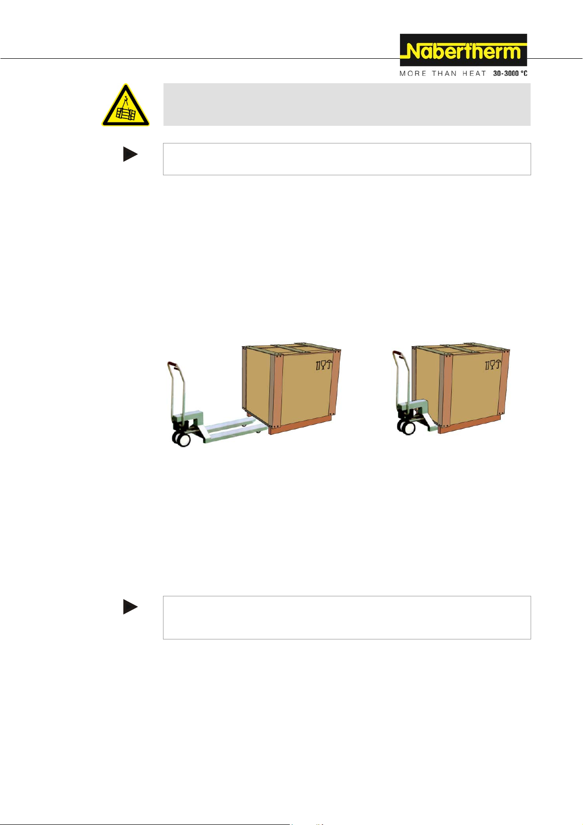
Transportation with a Pallet Truck
Observe the maximum permitted capacity of the pallet truck.
1. Our furnaces are delivered ex works on wooden frames to facilitate unloading.
Transport the furnace in its original packaging and with suitable equipment to
prevent any damage. Remove the packaging only when the furnace is in its final
location. When transporting the furnace, make sure it is secured against sliding,
toppling over, and damage. The furnace should be transported and installed by at
least two persons. Do not store the furnace in damp rooms or outdoors.
2. Push the pallet truck underneath the transportation frame. Make sure that the pallet
truck is completely beneath the frame. Pay attention to neighboring goods.
Fig. 12: Pallet truck is pushed completely beneath the transportation frame
3. Lift the furnace carefully and pay attention to its center of gravity. When the furnace
is being lifted, make sure that the ends of the forks or the load do not catch on
neighboring goods.
4. Make sure that the furnace is balanced safely; if not, attach securing equipment.
Push the furnace carefully, slowly and with the pallet truck at its lowest position. Do
not transport the furnace on inclines.
5. Carefully lower the furnace at its final position. Pay attention to neighboring goods.
Try not to set it down too abruptly.
Pos: 132 /TD/Allgemeine Hinweise (für alle Anleitungen) /Hinweis - In Deutschland ist die allgemeine Unfal lverhütungsvorschrift zu beachten. @ 3\mod_119366 7801739_51.docx @ 26122 @ @ 1
a
Note
In Germany, the general accident protection guidelines must be observed. The national
accident prevention regulations of the country of operation apply.
31
Page 32

Pos: 133 /TD/Sicherheit/Sicherheitssymbole/ W arnhinweise-ISO-ANSI/Warnsymbol_Vorsic ht - Rutschen/Kippen des Gerätes - Piktogramm Kippen/ Heben/Anheben @ 9\mod_1247064081950_51.doc x @ 62955 @ @ 1
Pos: 134 /TD/Transport_Montage_Inbetriebnahme/E r stinbetriebnahme/Legende für Packstücke z.B . zerbrechlich @ 1\mod_1173776713307_51.doc x @ 1074 6 @ @ 1
CAUTION
• Device may slip or topple over.
• Damage to the device.
• Risk of injury from lifting
heavy loads.
• Transport device only in original
packaging.
• Several people must carry the device.
Symbols:
The international standard symbols for handling packaging are defined in ISO R/780
(International Organization for Standardization) and in DIN 55 402 (German
Institute for Standardization).
Description Symbol Explanation
Fragile
This symbol is to be attached to fragile goods. Goods
marked like this are to be handled carefully and must
not be thrown or tied up.
This side up
The freight must be transported, transshipped, and
stored in such a way that the arrows point upward. The
freight must not be rolled, folded, or stored on edge.
However, the package does not have to be packed on
top of other freight.
Keep dry
Products with this symbol must be protected against
high air moisture, hence, they must be stored under
cover. If particularly heavy or bulky packages cannot
be stored in halls or sheds, they must be covered
carefully with a tarpaulin or similar.
Sling here The symbol shows only where the sling should be
attached, not the method of slinging. If the symbols
are at an equal distance from the middle or center of
gravity of the package, the package hangs straight if
the slings are the same length. If this is not the case,
the sling on one side has to be shortened.
32
Page 33

Pos: 135 /TD/Transport_Montage_Inbetriebnahme/Er stinbetriebnahme/Überschrift - Auspac ken (N 7/H - N 17/HR) @ 123\mod_1465300388429_51.docx @ 545754 @ 2 @ 1
4.2 Unpacking (N 7/H - N 17/HR)
Pos: 136 /TD/Transport_Montage_Inbetriebnahme/E r stinbetriebnahme/Auspacken kleine Öfen mit S tü lpkarton - Teil 1 @ 2\mod_1184739616497_51.docx @ 20026 @ @ 1
Wear protective
gloves
1. Check the transportation packaging for possible damage.
2. Remove tensioning straps from the transportation packaging.
3. Slacken screws and remove wooden casing from the covering box (if available 3a).
Pos: 137 /TD/Transport_Montage_Inbetriebnahme/Er stinbetriebnahme/Auspacken Kammerofen N 7/ H - N 17/ HR - Teil 2-Grafik @ 123\mod_1465300220645_51.doc x @ 545728 @ @ 1
Pos: 138 /TD/Transport_Montage_Inbetriebnahme/Er stinbetriebnahme/Stülpkarton vorsic htig anheben und von der Palette über die Tragegurte ... - (kleine Öfen) - Text @ 124\mod_1465808729563_51.docx @ 547576 @ @ 1
4. Carefully lift the cardboard box and remove it from the pallet.
5. Remove the foil and packaging material. Compare the delivered items with the
delivery note and the order documents, see "Delivery".
6. With two people, carefully lift the furnace out of the lower packaging unit, using the
lifting straps on the furnace. We recommend that you attach the lifting straps
around the sides (across) beforehand so that you can lift the furnace out of the
packaging unit.
33
Page 34

Pos: 139 /TD/Transport_Montage_Inbetriebnahme/Er stinbetriebnahme/Auspacken-Tragen Labor ofen - LHT-Tischmodell - Teil 3 @ 3\mod_1192436920381_5 1.docx @ 23483 @ @ 1
7. To carry, grip furnace from below at the sides and make sure you have a firm grip.
8. For furnaces weighing more than 25 kg, transport work must be carried out by at
least 2 people. If transport straps are used, they must be attached crosswise only.
Ensure that they are secure.
Note
In Germany, the general accident protection guidelines of VBG or BGZ must be observed.
The national accident prevention regulations of the country of operation apply.
Note
Save the packaging for possible shipping or for storing the furnace.
Pos: 140 /TD/Transport_Montage_Inbetriebnahme/Er stinbetriebnahme/Überschrift - Auspac ken (N 31/H - N 87/H) @ 123\mod_1465302308472_51.docx @ 545807 @ 2 @ 1
4.3 Unpacking (N 31/H - N 87/H)
Pos: 141 /TD/Transport_Montage_Inbetriebnahme/Er stinbetriebnahme/Auspacken Kammerofen N 31/ H - N 87/ H -Teil 1-Grafik @ 123\mod_1465302205408_51.doc x @ 545781 @ @ 1
Wear protective
gloves
Pos: 142 /TD/Transport_Montage_Inbetriebnahme/Er stinbetriebnahme/Auspacken-Überprüf en Sie die Transportverpackung auf eventuelle Schäden ... -Teil 1-Beschreibung @ 47\mod_1378976631990_51.docx @ 246295 @ @ 1
1. Check the transport packaging for any signs of damage. The packaging differs
depending on size, weight or installation site and, based on this, is provided in one
of the following ways. On a pallet, in a wooden cage or in a wooden box (shown in
figures 1a to 1c).
34
Page 35

Pos: 143 /TD/Transport_Montage_Inbetriebnahme/Er stinbetriebnahme/Auspacken-Kammerof en N 31/ H - N 87/H - Teil 2-Grafik @ 123\mod_1465303243672_51.doc x @ 545836 @ @ 1
Pos: 144 /TD/Transport_Montage_Inbetriebnahme/E r stinbetriebnahme/Auspacken-Schrauben/ Krampen lösen danach umlaufenden Holzverschlag vorsichtig...-Teil 2-Beschreibung @ 47\mod_1378976773803_51.docx @ 246345 @ @ 1
Pos: 145 /TD/Transport_Montage_Inbetriebnahme/Er stinbetriebnahme/Überschrift - Transpor t mit geeignetem Flurförderfahrzeug (Einzug Mitte) @ 48\mod_1383212440500_51.docx @ 251590 @ @ 1
Pos: 146 /TD/Transport_Montage_Inbetriebnahme/Er stinbetriebnahme/Auspacken-Kammerof en N 31/ H - N 87/H -Teil 4 - Hubwagen-Gabelstapler - Grafik @ 123\mod_146 5303 550348_51.docx @ 545862 @ @ 1
2. Remove screws/staples and then carefully remove the wooden siding from around
the base. Remove any plastic transportation sheeting.
3. Remove any transportation sheets, straps and packaging materials.
Transportation with suitable forklift truck
Pos: 147 /TD/Transport_Montage_Inbetriebnahme/E r stinbetriebnahme/Rahmen des Ofens besteht aus di ckwandigen Profilstählen. Fahren Sie mit den Gabelst ap lerzinken ... @ 75\mod_1413789817605_51.docx @ 334342 @ @ 1
Pos: 148 /TD/Transport_Montage_Inbetriebnahme/Er stinbetriebnahme/Hinweis - Es wird empfohlen, di e A n lage über längere Strecken bzw. über unebenen Boden mit eine m ... @ 47\mod_1378977035927_51. docx @ 246445 @ @ 1
Pos: 149 /TD/Allgemeine Hinweise (für alle Anleitungen) /Hinweis - In Deutschland ist die allgemeine Unfal lverhütungsvorschrift zu beachten. @ 3\mod_119366 7801739_51.docx @ 26122 @ @ 1
a
4. The furnace frame is made of thick steel sections. Drive the forklift forks under the
furnace watching out for fragile parts such as attachments and cables. Remove as
necessary. Make sure that the forks of the forklift are completely under the frame.
Mind the nearby transported goods.
Carefully lift the furnace from below minding the center of gravity. When lifting
make sure that the fork tips or the load itself do not get caught on nearby stacked
goods. Drive carefully, slowly and in the lowest position. Do not drive over any
steep surfaces. When the installation site is reached, lower the base carefully on the
wheels. Avoid any sudden drops.
Caution
We recommend that the system be moved to the installation site over longer distances or
over bumpy surfaces using a forklift or a pallet lift.
Note
In Germany, the general accident protection guidelines must be observed. The national
accident prevention regulations of the country of operation apply.
35
Page 36

Pos: 150 /TD/Transport_Montage_Inbetriebnahme/Er stinbetriebnahme/Überschrift - Transpor tsicherung/Verpackung @ 0\mod_1167826775847 _51. docx @ 5229 @ 2 @ 1
4.4 Transportation Securing Equipment/Packaging
Pos: 151 /TD/Transport_Montage_Inbetriebnahme/E r stinbetriebnahme/Verpackung - Allgemeine Hin weise zur Verpackung - keine spezielle Transportsi cherung @ 1\mod_1171004073117_51.docx @ 9153 @ @ 1
Note
No special transportation securing equipment is available for this furnace
The furnace packaging prevents damage during transportation. Make sure that you remove
all packaging material (also inside the furnace chamber). All packaging material can be
recycled. The packaging was designed so that no special description is necessary.
Pos: 152 /TD/Transport_Montage_Inbetriebnahme/Er stinbetriebnahme/Verpackung - Allgemeine Hin weise zur Verpackung - Kinder und Verpackungsmaterial @ 13\ mod_1290686355811_51.docx @ 109504 @ @ 1
Safety information
Do not allow children to play with packaging parts. They are at risk of suffocation from
folding boxes and plastic film.
Pos: 153 /TD/Transport_Montage_Inbetriebnahme/Er stinbetriebnahme/Verpackung - Allgemeine Hin weise zur Verpackung - Kammerofen N 7/H - N 87/H @ 123\mod_1465304 013 540_51.docx @ 545888 @ @ 1
1 Remove the plastic transportation sheet for the protection of the surrounding insulation.
Fig. 13: Removing the transportation protection
Pos: 154 /TD/Allgemeine Hinweise (für alle Anleitungen) / Hinweis - Bewahren Sie die Verpackung für einen eventue l len Versand oder für die Lagerung des @ 3\mod_1193667898805_ 51.docx @ 26135 @ @ 1
Pos: 155 /TD/Transport_Montage_Inbetriebnahme/E r stinbetriebnahme/Überschrift - Baulic he- und Anschlussvoraussetzungen @ 0\mod_1167826890943_ 51.docx @ 5238 @ 2 @ 1
Note
Please keep the packaging for possible shipping or storing of the furnace.
4.5 Constructional and Connection Requirements
Pos: 156 /TD/Transport_Montage_Inbetriebnahme/E r stinbetriebnahme/Überschrift - Auf stellung (Standort des Ofens) @ 2\mod_1184848718972_51.doc x @ 20166 @ 3 @ 1
4.5.1 Installation (Furnace Location)
Pos: 157 /TD/Transport_Montage_Inbetriebnahme/E r stinbetriebnahme/Beim Aufstellen des Ofens si nd folgende Sicherheitshinweise zu beachten: @ 49\mod_1 383725883608_51.docx @ 252635 @ @ 1
Pos: 158 /TD/Transport_Montage_Inbetriebnahme/Er stinbetriebnahme/Aufstellung - Kammeröf en/ Laboröfen - Beispiel: Tischmodelle @ 49\mod_1383733532 126_51.docx @ 252785 @ @ 1
When setting up the furnace, these safety instructions must be followed:
The furnace must be installed in a dry room in accordance with the safety instructions.
The table/supporting surface must be flat to enable the furnace to be installed straight.
Place the furnace on a non flammable surface (fire safety class A DIN 4102 –
Example: concrete, tiles, glass, aluminum or steel) so that any hot material falling
from the furnace cannot ignite the surface.
36
Page 37

Pos: 159 /TD/Transport_Montage_Inbetriebnahme/Er stinbetriebnahme/Aufstellort (für Kam mer öf en Arts & Crafts oder Rohröfen) @ 49\mod_1384335338473_51. docx @ 252895 @ @ 1
Pos: 160 /TD/Transport_Montage_Inbetriebnahme/Er stinbetriebnahme/Ofen- und Schaltanlage sin d nicht für den Betrieb im Freien ausgelegt. @ 49\mod_138373 092 2710_51.docx @ 252760 @ @ 1
Pos: 161 /TD/Transport_Montage_Inbetriebnahme/Er stinbetriebnahme/Mindestsicherheitsa bstand zu brennbaren Materialien - Kammeröfen N 7/ H - N 87/H - Grafik @ 123\mod_1465305195008_51.docx @ 545914 @ @ 1
The carrying capacity of the table must be designed to bear the weight of the furnace
incl. accessories.
The floor covering must be made of nonflammable material so that hot material
falling out of the furnace will not cause the floor covering to ignite.
Installation Location
The operator is responsible for adequate ventilation by installing the appropriate
systems to supply fresh air and to vent exhaust air. If a batch emits gases or vapors,
adequate ventilation of the installation site must be provided as well as a suitable
exhaust air venting system. A suitable vent for combustion exhaust must be supplied
by the customer
Make sure that the heat radiated by the furnace is vented (consult a ventilation expert,
if necessary)
Although the furnace is well-insulated, the exterior surfaces of the furnace radiate
heat. If necessary, this heat must be dissipated (a ventilation technician may need to
be consulted). In addition, a minimum clearance (S) of 0.5 m on all sides and 1 m
above the furnace must be maintained to flammable materials. In individual cases,
more space must be chosen in order to match the local conditions. For nonflammable
materials, the minimum side clearance can be reduced to 0.2 m.
The furnace must be protected against weather and caustic atmospheres. Nabertherm
accepts no liability or warranty claim for any corrosion damage as a result of
installation in damp surroundings or for similar reasons.
The furnace and switchgear are not designed to be operated outdoors.
Pos: 162 /TD/Sicherheit/Sicherheitssymbole/W arnhinweise-ISO-ANSI/Warnsymbol_Gefahr - Brandgefahr - Piktogramm Brandgefahr @ 9\mod_1247148035 738_ 51.docx @ 63010 @ @ 1
Fig. 14: Minimum safety distance to flammable materials (similar to picture)
DANGER
• Fire- danger to health.
• Risk of fatal injury.
• Adequate ventilation must be ensured at the
installation location to conduct waste heat and any
exhaust gases away.
37
Page 38

Pos: 163 /TD/Sicherheit/Sicherheitssymbole/W arnhinweise-ISO-ANSI/Warnsymbol_Gefahr - Gefahren durch automatische Löscheinrichtungen (W asser_Löschgas) @ 55\mod_1391587048048_51.doc x @ 269740 @ @ 1
• Danger associated with the use of an atomatic extinguishing
system
• Mortal danger posed by electrocution through wetness,
suffocation caused by extinguishing gas, etc.
• If automatic extinguishing systems are in place to fight fires and
protect the building, e.g. sprinkler systems, care must be taken
during their planning and installation that no additional hazards are
created, for example by extinguishing a pilot light, mixing
hardening oil and extinguishing water, the disablement of
electrical equipment, etc.
Pos: 164 /TD/Transport_Montage_Inbetriebnahme/E r stinbetriebnahme/Überschrift - Montage, Ins tallation und Anschluss @ 0\mod_1167827976269_ 51. docx @ 5292 @ 2 @ 1
4.6 Assembly, Installation, and Connection
Pos: 165 /TD/Transport_Montage_Inbetriebnahme/Er stinbetriebnahme/Überschrift - 1.1. 1 Abluf tführung @ 0\mod_1167828513042_51.docx @ 5310 @ 3 @ 1
4.6.1 Venting Exhaust Fumes
Pos: 166 /TD/Transport_Montage_Inbetriebnahme/E r stinbetriebnahme/Beim Heizen des Ofens können gesu ndheitsschädliche Gase und Dämpfe freigesetzt werden. - Text_01 @ 124\mod_1465549022354_51.docx @ 546846 @ @ 1
When the furnace is heating, hazardous gases and vapors may be released. Therefore,
"exhaust gases" emitted from the exhaust air opening must be directed outdoors in a
suitable manner (example: ventilate the working area). If adequate ventilation cannot be
ensured at the working area, the "exhaust gases" must be removed via a suitable pipe. We
recommend that you install a suitable extraction flue above the furnace or, if this is already
Pos: 167 /TD/Transport_Montage_Inbetriebnahme/E r stinbetriebnahme/Als Abzugsrohr kann hande lsübliches Abgasrohr aus Metall verwendet werden. - Text_02 @ 124\mod_1465550321485_51.docx @ 546872 @ @ 1
Pos: 168 /TD/Transport_Montage_Inbetriebnahme/Er stinbetriebnahme/Für die Abgasführung ist ei ne m a ximale Temperatur der Abluft von ca. 200 °C anzunehmen. - Te xt_0 3 @ 124\mod_1465550327530_51.docx @ 546898 @ @ 1
Pos: 169 /TD/Transport_Montage_Inbetriebnahme/Er stinbetriebnahme/Größe und Ausführung der Abgasf ü hrung ist durch einen Lüftungstechniker auszuleg en. - Text 04 @ 124\mod_1465550334477_51.docx @ 546924 @ @ 1
Pos: 170 /TD/Transport_Montage_Inbetriebnahme/Er stinbetriebnahme/Abluftverrohrung Kammer of en N 7/H - N 87/H - Grafik @ 123\mod_1465306153640_51.doc x @ 5459 40 @ @ 1
installed on the furnace, connect suitable extraction pipes and remove the exhaust gases.
A suitable metal exhaust gas pipe can be used. Use only metal pipes (example: stainless
steel). It must be attached facing upwards and be fixed to the wall or ceiling.
A maximum exhaust gas temperature of approx. 200 °C can be assumed for the exhaust
system. There is a risk of burning at the bypass connection and the piping. The wall duct
(1) must be made from heatproof material.
The size and design of the exhaust system must be defined by a ventilation engineer.
DANGER
Fig. 15: Example: Installation of exhaust air piping (similar to picture)
38
Page 39

Pos: 171 /TD/Allgemeine Hinweise (für alle Anleitungen) /Hinweis - Es ist zu gewährleisten, dass durch die ausstr ömende heiße Luft über die Abluftverrohrung @ 51\mod_13 86856845336_51.docx @ 258260 @ @ 1
Caution
Steps must be taken to ensure that the flow of hot air emitted from the furnace's exhaust
outlet flap is not hazardous to people, property or the building.
Pos: 172 /TD/Allgemeine Hinweise (für alle Anleitungen) /Hinweis - Die Abgase können nur abgeleitet werden, wenn der Raum über eine entsprechende Zuluft ... @ 4\mod_1202738777690_51.docx @ 30973 @ @ 1
Note
The exhaust gases can only be discharged if the room is aerated via an appropriate supply
air opening.
Pos: 173 /TD/Allgemeine Hinweise (für alle Anleitungen) /Hinweis - Kundenseitige Dach- und oder Mauerarbeit en sind durch die Abgasführung notwendig ... @ 3\mod_1193323429727_51.doc x @ 25993 @ @ 1
Note
Roof work and/or masonry by the customer is required for the exhaust gas discharge. The
size and design of the exhaust gas discharge must be determined by a ventilation technician.
The national regulations of the local country apply.
Pos: 174 /TD/Transport_Montage_Inbetriebnahme/Er stinbetriebnahme/Überschrift - Einlegen d er Bodenplatte LHT-Ofen @ 2\mod_1185287183100_51.doc x @ 20422 @ 3 @ 1
4.6.2 Insertion of the Base Plate
Pos: 175 /TD/Ersatz-/Verschleißteile/Den Lief erumfang mit dem Lieferschein und den Auftragspapiere n vergleichen. Fehlende Teile und ... @ 105\mod_1444835179166_51. docx @ 414590 @ @ 1
Compare the delivered items with the delivery note and the purchase order documents.
Immediately notify the carrier and Nabertherm GmbH of any missing or damaged parts, as
Pos: 176 /TD/Transport_Montage_Inbetriebnahme/Er stinbetriebnahme/Einlegen der Einlegepla tte (Bodenplatte) HT 04/16-HT 450/18-Öfen - Text (1) @ 21\mod _133 1110613720_51.docx @ 151215 @ @ 1
Pos: 177 /TD/Transport_Montage_Inbetriebnahme/E r stinbetriebnahme/Hinweis - Es ist darauf zu ac hten, dass die Belastung des Bodens 2 kg/dm2 nicht überschrei tet @ 2\mod_1185287451644_51.docx @ 20435 @ @ 1
complaints received at a later date cannot be acknowledged.
Carefully place the insert plate(s) *) (number of insert plates depends on the furnace
model), distributed across the floor of the furnace, starting from the middle. When placing
the insert plate(s) make sure that neither the door collar nor the heating elements are
damaged. Absolutely avoid touching the heating elements when inserting the heating
plate(s). Contacting the heating elements can result in their immediate destruction.
The furnace floor is made of high-quality refractory material but this material is highly
sensitive to impact or pressure.
Some models are supplied with one insert plate as a standard in order to prevent the soft
furnace floor from being damaged. Nabertherm accepts no liability for damage (e.g.
depressions) in the furnace floor resulting from not using these insert plates. *) Damaged
insert plate(s) must be immediately replaced with new ones (see the section "Spare
Parts/Wearing Parts").
The charge must be positioned in the furnace chamber, on the floor, as centered as possible.
This ensures uniform heating.
After charging, the furnace door must be closed carefully.
*) in scope of delivery depending on the design/furnace model
Note
It must be ensured that the load on the furnace base does not exceed 2 kg/dm
2
.
39
Page 40

Pos: 178 /TD/Transport_Montage_Inbetriebnahme/Er stinbetriebnahme/Einlegen der Einlegepla tte (Bodenplatte) LHT/HTC/HTCT-Öfen - Grafi k ( 1) @ 21\mod_1331045314067_51.docx @ 151165 @ @ 1
Pos: 179 /TD/Transport_Montage_Inbetriebnahme/E r stinbetriebnahme/Da sich SiC-Platten ständi g au sdehnen, sollten die Platten nach ca. 3-5 Jahren gewechs elt werden. @ 60\mod_1400057392869_51.docx @ 293244 @ @ 1
Fig. 16: Inserting the ceramic insert plate (in scope of delivery depends on design/furnace
model)
Note
Since SiC plates expand continuously, they should be replaced after about 3-5 years.
Otherwise there is a risk that the collar bricks will be pushed outwards. In this case, we will
not accept warranty claims.
Pos: 180 /TD/Transport_Montage_Inbetriebnahme/E r stinbetriebnahme/Überschrift - Montage des Con trollers (modellabhängig) @ 51\mod_138660536666 1_51.docx @ 257500 @ 3 @ 1
4.6.3 Assembling the Controller (Depending on the Model)
Pos: 181 /TD/Transport_Montage_Inbetriebnahme/Er stinbetriebnahme/Controller_B01 - Der i m Lieferumfang befindliche Halter des Controllers ( modellabhängig) ist am ... @ 104\mod_1444203310032_51.docx @ 412813 @ @ 1
Pos: 182 /TD/Transport_Montage_Inbetriebnahme/E r stinbetriebnahme/Controller_B02 - An der Posi tion des Controllers befinden sich Schrauben (1) zur Montage des Halters @ 104\mod_1444203435587_51.doc x @ 412839 @ @ 1
Pos: 183 /TD/Transport_Montage_Inbetriebnahme/Er stinbetriebnahme/Controller_B03 - Halter mit de n vorher gelösten Schrauben am Ofen auf richtige Positi on set zen und @ 104\mod_1444203580848_51.docx @ 412865 @ @ 1
Pos: 184 /TD/Transport_Montage_Inbetriebnahme/E r stinbetriebnahme/Controller_B04 - Montage de s Halters an das Ofengehäuse_Controller einsetzen - Graf ik @ 104\mod_1444203746764_51.docx @ 412891 @ @ 1
Pos: 185 /TD/Transport_Montage_Inbetriebnahme/Er stinbetriebnahme/Controller_B05 - Schr auben des Halters fest anziehen und auf sicheren Halt überprüfen @ 104\ mod_1444204784863_51.docx @ 412917 @ @ 1
Attach the supplied controller with holder (model-related) to the furnace.
At the controller position there are screws to attach the holder; these must be unscrewed
beforehand.
Place the controller holder (2) with the screws loosened on to the correct position on the
furnace and fasten it with suitable tools (3).
Fig. 17: Install the holder on the furnace housing (similar to picture)
40
Page 41

Pos: 186 /TD/Transport_Montage_Inbetriebnahme/E r stinbetriebnahme/Controller_B06 - Schr auben des Halters fest anziehen - Grafik @ 104\mod_144420502 8724 _51.docx @ 412943 @ @ 1
Pos: 187 /TD/Transport_Montage_Inbetriebnahme/Er stinbetriebnahme/Controller_C01 - Der Contr oller ist an dem Ofen befindlichen Halter einzusetze n @ 103\mod_1442499950347_51.docx @ 409670 @ @ 1
Pos: 188 /TD/Transport_Montage_Inbetriebnahme/Er stinbetriebnahme/Controller_B07 -Contr oller in die befindliche Halterung einsetzen - TOP_F- HO - Graf ik @ 104\mod_1444209154288_51.docx @ 412969 @ @ 1
Tighten the screws (3) of the holder and check that is sits properly (4).
Fig. 18: Tighten the screws on the holder (similar to picture)
Place the controller in the holder on the furnace.
Pos: 189 /TD/Transport_Montage_Inbetriebnahme/E r stinbetriebnahme/Controller_C02 - Achten Si e dar auf, dass der Controller vollständig in die bef indliche Halterung ... @ 103\mod_1442497835549_51.docx @ 409592 @ @ 1
Pos: 190 /TD/Transport_Montage_Inbetriebnahme/Er stinbetriebnahme/Controller_C03 - Contro ller in den am Ofen befindlichen Halter einsetzen - Graf i k @ 103\mod_1442498084763_51.docx @ 409618 @ @ 1
Fig. 19: Place the controller in the holder (similar to picture)
Make sure that the controller is placed correctly in the holder. If this is ignored, the
controller may be damaged or destroyed. Nabertherm accepts no liability if the controller is
not handled properly.
Fig. 20: Place the controller in the holder on the furnace (similar to the picture)
41
Page 42

Pos: 191 /TD/Transport_Montage_Inbetriebnahme/E r stinbetriebnahme/Überschrift - Montage ein es Abzugskamins, Abzugskamin mit Ventilator oder Abzugs... (N7/H - N17/HR) @ 127\mod_1467876549558_51.docx @ 554831 @ 2 @ 1
4.7 Installation of an Extraction Flue, Extraction Flue with Fan or Extraction Flue
with Fan and Catalyst (Accessories for N 7/H – N 17/HR)
Pos: 192 /TD/Transport_Montage_Inbetriebnahme/E r stinbetriebnahme/Abzugskamin Laboröfen - all gemeiner Text @ 14\mod_1300115642723_51.docx @ 113432 @ @ 1
Which vents are supplied vary depending on the application/order (does not apply to
protective gas connection):
Pos: 193 /TD/Transport_Montage_Inbetriebnahme/E r stinbetriebnahme/Überschrift - Abzugska min mit Ventilator (Einzug Mitte) @ 127\mod_146787728720 2_51.docx @ 554858 @ @ 1
Pos: 194 /TD/Transport_Montage_Inbetriebnahme/E r stinbetriebnahme/Abzugskamin - Abzugskamin mit Ventilator @ 107\mod_1448887280088_51.doc x @ 435169 @ @ 1
Pos: 195 /TD/Transport_Montage_Inbetriebnahme/E r stinbetriebnahme/Abzugskamin - Abzugska min mit Ventilator (N 7/H - N 17/HR) - Grafik @ 127\mod_146788423 8156 _51.docx @ 554936 @ @ 1
Vent with fan
Supports the venting of gases and vapors from the furnace chamber. Exhaust air cross
section: 85 x 60 mm
Install by slipping the vent onto the connecting piece on the back wall of the furnace
and fasten it with the screws included in the scope of delivery. Plug the connecting
plug into the socket on the back of the switchgear (optional) or in an external socket.
Pos: 196 /TD/Transport_Montage_Inbetriebnahme/E r stinbetriebnahme/Überschrift - Abzugska min mit Lüfter und Katalysator (Einzug Mitte) @ 127\ mod_1467877581581_51.docx @ 554884 @ @ 1
Pos: 197 /TD/Transport_Montage_Inbetriebnahme/E r stinbetriebnahme/Abzugskamin - Abzugska min mit Lüfter und Katalysator @ 107\mod_1448887655840_51. docx @ 435223 @ @ 1
Fig. 21: Vent with fan
Vent with Fan and Catalytic Converter
Heats the gases and vapors from the furnace chamber to approx. 600 °C and feeds it
through the catalytic converter honeycomb. The converter incinerates most of the
organic substances, i.e. breaks them down into carbon dioxide and steam. This largely
eliminates any annoying odors (for example, during dewaxing).
Warning! Inorganic substances such as heavy metals halogens, silicons and
particulates (even in small quantities) will destroy the catalytic converter!
The temperature of the catalytic converter must be checked; from the start of the
program the converter must be operating at approx. 600 °C. A statement cannot be
made regarding residues which may be released into the environment. This is largely
dependent on the individual materials/embedding masses used and their compositions.
Exhaust air cross section: 120 x 120 mm
Installation: Fasten the U-shaped brackets to the back wall of the furnace using the
screws included in the scope of delivery, slide the included section of pipe onto the
connecting piece of the furnace and screw the vent (with CAT) firmly to the bracket.
Plug the power plug into the socket on the back side (optional) of the switchgear or
into an external socket.
42
Page 43

Pos: 198 /TD/Transport_Montage_Inbetriebnahme/E r stinbetriebnahme/Abzugskamin - Abzugska min mit Lüfter und Katalysator (N7/H - N 17/HR) - Grafik @ 127\mod_1467 883824109_51.docx @ 554910 @ @ 1
Fig. 22: Catalytic converter
Pos: 199 /TD/Transport_Montage_Inbetriebnahme/E r stinbetriebnahme/Überschrift - 1.1. 1 Ansc hluss an das Elektronetz @ 0\mod_1168599727688_51.doc x @ 6050 @ 3 @ 1
4.7.1 Connecting the Furnace to the Power Supply
Pos: 200 /TD/Transport_Montage_Inbetriebnahme/E r stinbetriebnahme/Anschluss an das Elektronet z - für alle Standardöfen @ 113\mod_1456924078390_51. docx @ 451432 @ @ 1
On the building side, the required services must be provided, i.e. the carrying capacity of
the installation surface, provision of power (electricity), etc.
The furnace must be installed in accordance with its intended use. The power
connection values must correspond to the values on the furnace type plate.
The power socket must be located close to the furnace and must be easily accessible.
The safety requirements are not met if the furnace is not connected to a socket with
grounding contact.
On use of an extension cable or a multipoint socket, the maximum electrical rating
must not be exceeded. Do not use the furnace with an extension cable if you are
uncertain whether grounding is guaranteed.
The power cable must not be damaged. Do not place any objects on the power cable.
Route the cable so that nobody can tread on or stumble over it.
A damaged power cable must be replaced immediately.
Pos: 201 /TD/Transport_Montage_Inbetriebnahme/E r stinbetriebnahme/Hinweis - Vor dem Anschluss der S pann ungsversorgung sicherstellen, dass der Net zsc halter sich ... @ 51\mod_1387370782838_51.doc x @ 258640 @ @ 1
Ensure that the furnace's connection cable is routed so that it is protected.
Note
Before connecting the power, make sure that the power switch is set to "Off" or "0".
Pos: 202 /TD/Transport_Montage_Inbetriebnah me/Er stinbetriebnahme/Anschluss an das Elektr onet z_Netzanschluss mit Netzzuleitung @ 36\mod_13 6059 8965567_51.docx @ 209964 @ @ 1
Power Connection with Plug-In Power Line:
When you plug the power plug into an appropriate socket check the type plate for
specifications related to mains voltage, mains type and max. power requirement. The
distance between the furnace and the socket should be as short as possible. Extensions must
be avoided.
The power plug (furnace with feeder) enables the furnace and control box to be connected
and disconnected from the power grid.
The power plug must be easy to reach while the furnace is in operation to be able to pull it
quickly in case of emergency (see section entitled "What to do in an emergency").
43
Page 44

Pos: 203 /TD/Transport_Montage_Inbetriebnahme/E r stinbetriebnahme/Anschluss an das Elektr onet z - Ofen bis 3600 Watt (beiliegendes Netzkabel im ...) - Grafik @ 51\mod_1387378147753_51.docx @ 258840 @ @ 1
Pos: 204 /TD/Transport_Montage_Inbetriebnahme/E r stinbetriebnahme/Anschluss an das Elektr onet z - Das im Lieferumfang befindliche Netzzuleitungs kabe l mit „Snap-In-Kupp @ 51\mod_1387370803087_51.doc x @ 258690 @ @ 1
Pos: 205 /TD/Transport_Montage_Inbetriebnahme/E r stinbetriebnahme/Anschluss an das Elektronet z - Ofen ab 3600 Watt (CEE Stecker) - Grafik @ 73\mod_14099026 3466 4_51.docx @ 326040 @ @ 1
Fig. 23: Furnace up to 3600 kW (the power cable is supplied) (similar to picture)
1. Plug the supplied connection cable with snap-in coupling into the rear wall of the
furnace.
2. Then connect the power cable to the power supply. Use only a grounded socket.
Pos: 206 /TD/Transport_Montage_Inbetriebnahme/E r stinbetriebnahme/Anschluss an das Elektr onet z - Schließen Sie das Netzkabel am Netzanschluss an. - Kammeröfen @ 102\mod_1439796253996_51.docx @ 406260 @ @ 1
Pos: 207 /TD/Transport_Montage_Inbetriebnahme/ Er stinbetriebnahme/Anschluss an das Elektr onet z_Netzanschluss ohne Netzzuleitung @ 36\mod_1360 598 971056_51.docx @ 209989 @ @ 1
44
Fig. 24: Furnace from 3.600 W (CEE plug) (similar to picture)
1. Connect the power cable to the power supply. Use only a grounded socket.
Check the ground resistance (acc. to VDE 0100); see also accident prevention regulations.
Electrical systems and equipment according to DGUV V3.
Power Connection without Plug-In Power Line:
The power line must have a fixed connection in the switchgear cabinet, either at the
available terminals or, in models without a separate switchgear, to the main switch. When
carrying out this work pay attention to the specs on the type plate: network voltage and
type, and maximum power consumption.
The fuse protection and the cross-section of the required power connection depend on the
surrounding conditions, the length of the line and how it is installed. For this reason, the
type of protection and how it should be installed must be decided by a qualified electrician.
Page 45

Pos: 208 /TD/Allgemeine Hinweise (für alle Anleitungen) /Warnung - Arbeiten an der elektrischen Ausrüstun g dür fen nur von ... @ 2\mod_1184228021019_51.docx @ 19673 @ @ 1
Pos: 209 /TD/Transport_Montage_Inbetriebnahme/E r stinbetriebnahme/Anschluss an das Elektronet z_Unter bestimmungsgemäßen Betriebsbedingung en können Berührungsspa... @ 110\mod_1453736549519_51.docx @ 443 002 @ @ 1
Pos: 210 /TD/Allgemeine Hinweise (für alle Anleitungen) /Hinweis - Es gelten die nationalen Vorschrif ten des jeweiligen Verwendungslandes @ 43\mod_13714597908 61_51.docx @ 233745 @ @ 1
The power cable must not be damaged. Do not place any objects on the power cable.
Lay the cable so that nobody can step on it or trip over it.
The power line may only be replaced by an approved, equivalent line.
Ensure that the connection line of the furnace is protected.
This protection must be compliant with locally applicable standards and regulations.
Ensure that the protective conductor terminal is correct.
When several phases are involved, they must be connected with a clockwise rotating field
in the sequence L1, L2, L3.
Before you switch on the furnace for the first time make sure that a clockwise rotating
field is in place. This is a prerequisite for the smooth functioning of the furnace.
Warning - Danger of Electric Shock!
Work on the electrical equipment may be done only by qualified, authorized electricians.
The customer must provide the required services, such as ensuring the carrying capacity of
the setup location and provision of energy (electricity).
Pay attention to sufficient sizing and fuse protection of the power supply cable to suit
the characteristics of the furnace.
Ensure that the cable connecting the furnace and the switching system is laid out so
that it is protected.
Under normal operation conditions, contact voltages which may exceed the
operating current of an FI circuit breaker with personal protection can occur.
The requirements of EN 60519-2 “Safety in electroheat installations – Part 2:
Particular requirements for resistance heating equipment” are maintained for
electrical safety.
Check the grounding resistor (according to VDE 0100); also refer to the Accident
Prevention Regulations.
Electrical systems and equipment according to provision (DGUV V3) of the German
Trade Association.
Note
The national regulations of the respective country of operation apply.
Pos: 211 /TD/Sicherheit/Sicherheitssymbole/W arnhinweise-ISO-ANSI/Warnsymbol_Achtung - falsche Netzspannung - Piktogramm Gebotszeic hen @ 9\ mod_1247475231381_51.docx @ 63131 @ @ 1
NOTICE
• Danger from incorrect voltage
• Damage to the furnace.
• Check voltage before connecting and
commissioning the furnace.
• Compare the voltage with the details
on the type plate.
45
Page 46

Pos: 212 /TD/Sicherheit/Sicherheitssymbole/W arnhinweise-ISO-ANSI/Warnsymbol_Gefahr - Brandgefahr - Piktogramm Brandgefahr @ 9\mod_1247148035 738_ 51.docx @ 63010 @ @ 1
Pos: 213 /TD/Transport_Montage_Inbetriebnahme/Er stinbetriebnahme/Überschrift - Ersti nbetr i ebnahme @ 0\mod_1167828977720_51.docx @ 5337 @ 2 @ 1
4.8 Commissioning
Pos: 214 /TD/Transport_Montage_Inbetriebnahme/Er stinbetriebnahme/Erstinbetriebnahme L HT/N/NR/TR/NAC/RHTH-RHTV - Öfen - 1 @ 2\mod_1186641509092_ 51.docx @ 20833 @ @ 1
The furnace may be put into operation only by qualified persons and in compliance with the
safety instructions.
Read the section on "Safety". When the furnace is put into operation, the following safety
information must also be observed to prevent serious injury, damage to the furnace, and
damage to other property.
Make sure that the instructions and information in the controller instructions are observed
and followed.
The furnace may be used only for its intended purpose.
Ensure that only authorized persons remain in the working area of the furnace and that no
other persons are put at risk when the furnace is put into operation.
Before starting the furnace for the first time, make sure that all tools, foreign parts, and
transportation securing equipment have been removed.
Activate all safety equipment (power switch, emergency stop button if applicable) before
putting the furnace into operation.
Incorrectly wired connections may destroy electric/electronic components.
Observe the special protective measures (e.g. grounding, …) for components that are at
risk.
Faulty connections can cause the furnace to start unexpectedly.
Before you switch on the furnace, make sure that you know what to do in case of faults or
emergencies.
Before starting the furnace for the first time, check the electrical connections and control
displays.
Before placing materials in the furnace, check whether they could harm or destroy the
insulation or the heating elements. Materials that could damage the insulation include:
alkalis, alkaline earths, metal vapors, metal oxides, chlorine compounds, phosphorous
compounds, and halogens.
Pos: 215 /TD/Allgemeine Hinweise (für alle Anleitungen) /Hinweis - Überprüfen Sie vor dem ersten Einschalten, da ss ein rechtsdrehendes Drehfeld gewährleistet @ 3\ mod_1193748088308_51.docx @ 26369 @ @ 1
Caution
Before you switch on the furnace for the first time, make sure that the motor achieves a
clockwise rotating field. This is a prerequisite for the smooth functioning of the furnace.
Pos: 216 /TD/Allgemeine Hinweise (für alle Anleitungen) /Hinweis - Vor Inbetriebnahme des Ofens sollte die ser 24 Stunden am Aufstellungsort akklimatisiert . . @ 3\mod_1195568014336_51.docx @ 27871 @ @ 1
Note
Before starting the furnace for the first time, allow it to acclimatize at its installation
location for 24 hours.
DANGER
• Fire- danger to health.
• Risk of fatal injury.
• Adequate ventilation must be ensured at the
installation location to conduct waste heat and any
exhaust gases away.
46
Page 47

Pos: 217 /TD/Allgemeine Hinweise (für alle Anleitungen) /Hinweis - Bei Verwendung von Begasungskästen wird ei ne Arbeitstemperatur bis zu 1100 °C (2012 °F).. . @ 123\ mod_1465290938112_51.docx @ 545676 @ @ 1
Pos: 218 /TD/Transport_Montage_Inbetriebnahme/Er stinbetriebnahme/Die Bildung einer Oxidschi cht bei der Verwendung von Heizelementen - Heizwendel @ 99\ mod_1437112579759_51.docx @ 398170 @ @ 1
Note
If the protective gas boxes are used, a working temperature to 1100 °C (2012 °F) is
recommended; with working temperatures to 1150 °C (2102 °F) the boxes will suffer
increased wear.
The formation of a layer of oxide is necessary for the correct function of the heating
element.
This procedure is for the first start-up and must be repeated after every replacement of
heating elements.
The duration of the oxidation firing can be found in the section entitled "Recommendation
for Heating the Furnace for the First Time".
Nest formation is a natural process and
requires no correction. Considerable nest
formation, however, can influence
temperature distribution.
Before
Pos: 219 /TD/Betrieb_Bedienung/Überschrif t - Beschickung/Chargierung @ 0\mod_1167835476044_51. docx @ 5418 @ 2 @ 1
4.9 Loading/Charging
Pos: 220 /TD/Betrieb_Bedienung/Beschickung/Char gierung Niedertemperatur-Kammerofen N.../..HA - 1 @ 7\mod_1233738951757_51.docx @ 49239 @ @ 1
Only materials whose characteristics are known may be heated. Consult any available
safety data sheets for the materials.
Loading a very large quantity of material into the furnace chamber can substantially
lengthen the heating-up time.
If it can be at all avoided, do not open the furnace when it is hot. When it is necessary to
open the furnace at a high temperature, the time should be kept to an absolute minimum.
Personnel must wear the appropriate protective clothing, and the workspace must be
adequately ventilated as stated in the section entitled “Safety”.
Stainless steel sheet can discolor (especially if the furnace is opened while hot), but this
does not impair the functionality of the furnace.
Additional Precautionary Measures
Please make sure that objects such as teapots and bottles are kept away from the furnace.
Warning - Danger of Electric Shock!
For the protection of the operator and the furnace, the heating program must be stopped
before the furnace is loaded. Ignoring this warning can result in electric shock.
After (nest formation)
47
Page 48

Pos: 221 /TD/Transport_Montage_Inbetriebnahme/E r stinbetriebnahme/Überschrift - Empfehlun g für das erste Aufheizen des Ofens @ 0\mod_1167829134269_51. docx @ 5346 @ 2 @ 1
4.10 Recommendations for Heating the Furnace for the First Time
Pos: 222 /TD/Transport_Montage_Inbetriebnahme/E r stinbetriebnahme/Empfehlung für das erste Aufh eizen des Kammerofens N 41/H @ 30\mod_1349157982076_51. doc x @ 185140 @ @ 1
To generate an protective oxide coating on the heating elements the furnace must be
heated up over approx. 6 hours from a temperature of 100 °C (212 °F) to under the
maximum temperature (example: The furnace is designed for a maximum temperature of
approx. 1280 °C (2336 °F), that means that a temperature of approx. 1180 °C (2156 °F)
must be entered at the the controller. But this temperature must be reached over the full
period of 6 hours. The entered temperat ure (example: 1180 °C) must be held for
approx. 1 hour.
This procedure must be conducted when starting up for the first time, after heating elements
have been replaced, or to regenerate the oxide coating. During heating up noxious odors
may be emitted, this is due to the binding agent in the insulation material. We recommend
that the furnace location be well ventilated during the first warm-up phase. Let the furnace
cool down naturally to room temperature.
Pos: 223 /TD/Transport_Montage_Inbetriebnahme/E r stinbetriebnahme/Empfehlung für das erste Aufh eizen des Ofens HT 04/16-HT 450/18 - Öfen @ 34\mod_135523098864 0_51.docx @ 201886 @ @ 1
Pos: 224 /TD/Transport_Montage_Inbetriebnahme/Er stinbetriebnahme/Risse in der Isolierung - S tand ard - Text @ 6\mod_1222861412436_51.docx @ 43548 @ @ 1
Pos: 225 /TD/Transport_Montage_Inbetriebnahme/Er stinbetriebnahme/Bei Muffeln, Einsatzkäs ten, Rollengang oder Blechauskleidungen kann es zu Verzu g kommen. @ 30\mod_1349165659749_51.docx @ 185215 @ @ 1
Pos: 226 /TD/Allgemeine Hinweise (für alle Anleitungen) /Hinweis - Bei Verwendung von Begasungskästen wird ei ne Arbeitstemperatur bis zu 1100 °C (2012 °F)... @ 123\ mod_1465290938112_51.docx @ 545676 @ @ 1
Ventilate the furnace chamber during the initial heating up. If included, open the
exhaust-air flap/s. For furnaces without exhaust-air flap/s, alternatively, the door can
be opened during heating up a few cm for 30 seconds at a time. This procedure must
be repeated several times during the heating up phase.
Operate without the cooling blower function
Heat the furnace without a charge
Closing the door
Switch on the furnace/controller (see section "Operation")
Cracks in the Insulation
The insulation of the furnace consists of a very high-quality refractory material. Heat
expansion may cause cracks in the insulation even after a few heating cycles. However,
these have no effect on the functioning or quality of the furnace. This is no reason for a
complaint.
Wearing parts such as muffles, insert boxes, roller conveyors, charging plates or steel sheet
panels may warp.
Note
If the protective gas boxes are used, a working temperature to 1100 °C (2012 °F) is
recommended; with working temperatures to 1150 °C (2102 °F) the boxes will suffer
increased wear.
48
Page 49

Pos: 227 /TD/Transport_Montage_Inbetriebnahme/Er stinbetriebnahme/Risse in der Isolierung Ka m mer of en N 41/H - Grafik @ 30\mod_1349160598790_51.docx @ 185165 @ @ 1
before after
Fig. 25: Example: Cracks in the insulation after a few warm-up cycles.
Pos: 228 /TD/Betrieb_Bedienung/Überschrif t - Bedienung 1 @ 3\mod_1186740685002_51.docx @ 20988 @ 1 @ 1
5 Operation
Pos: 229 /TD/Betrieb_Bedienung/Controller/B 150/ B130/B170/C280/C290/C295/P320/Überschr i ft - Controller @ 2\mod_1186739941084_51.docx @ 20936 @ 2 @ 1
5.1 Controller
Pos: 230 /TD/Betrieb_Bedienung/Controller/B 400/ B410/C440/C450/P470/P480/Bedienfeld Contr oller B400/C440/P470 - Grafik/Text @ 67\mod_140845 4720 420_51.docx @ 314641 @ @ 1
B400/C440/P470
4 1 2 3
Fig. 26: Control field B400/C440/P470 (similar to picture)
No. Description
Display
1
49
Page 50

B400/C440/P470
Control keys for "Start/Hold/Stop", "Menu" selection, "Back" function and information menu selection
2
Jog dial
3
USB interface for a USB stick
4
Pos: 231 /TD/Allgemeine Hinweise (für alle Anleitungen) / Hinweis - Beschreibung der Eingabe von Temperaturen, Zeiten und „Starten“ des Ofens siehe separate A @ 3\mod_1188809 986550_51.docx @ 21015 @ @ 1
Note
See the separate operating instructions for a description of how to enter temperatures and
times and to "start" the furnace.
Pos: 232 /TD/Betrieb_Bedienung/Schaltanlage/ Überschrift - Bedien-, Anzeige- und Schaltelemen te ( je nach Ausführung) @ 18\mod_1314191961517_51.doc x @ 128024 @ 1 @ 1
6 Operation, Display and Switch Elements (depending on design)
Pos: 233 /TD/Betrieb_Bedienung/Controller/B 150/ B130/B170/C280/C290/C295/P320/Überschr i ft - Controller/Ofen einschalten @ 0\mod_1168947051 396_51.docx @ 6530 @ 2 @ 1
6.1 Turning on the Controller/Furnace
Pos: 234 /TD/Allgemeine Hinweise (für alle Anleitungen) /Überschrift - Öfen mit Netzstecker (Einzug link s) @ 7\mod_1232450264630_51.docx @ 48098 @ @ 1
Furnaces with power plug
Pos: 235 /TD/Betrieb_Bedienung/Controller/ B400/ B410/C440/C450/P470/P480/Symbole_Symbo ld arstellungen/Controller einschalten_Abl auf-Anzeige-Bemerkung - Tabelle @ 67\mod_14084428 1731 1_51.docx @ 314302 @ @ 1
Switching on the Controller
Steps Display Comments
Turn on the power
switch
Turn on the power switch by setting it to
"I"
(power switch type differs depending on
/
The overview screen
appears.
After a couple of
features/furnace model)
If the temperature is displayed at the
controller, the controller is ready to
operate.
seconds, the temperature
is displayed.
Pos: 236 /TD/Allgemeine Hinweise (für alle Anleitungen) /Überschrift - Öfen mit Hauptschalter (Einzug li nk s) @ 7\mod_1232450214124_51.docx @ 48083 @ @ 1
Furnaces with main switch
Pos: 237 /TD/Betrieb_Bedienung/Schaltanlage/ Funk tion 1 = Hauptschalter einschalten @ 1\mod_1170332064 185_51.docx @ 8727 @ @ 1
I ON
O OFF
Turn on main switch [1] I/ON
The furnace and switching system are connected to the power supply using the main power
switch.
Pos: 238 /TD/Betrieb_Bedienung/Controller/ B400/ B410/C440/C450/P470/P480/Symbole_Symbo ld arstellungen/Controller einschalten_Abl auf-Anzeige-Bemerkung - Tabelle @ 67\mod_14084428 1731 1_51.docx @ 314302 @ @ 1
Switching on the Controller
Steps Display Comments
Turn on the power
switch
Turn on the power switch by setting it to
"I"
(power switch type differs depending on
/
50
features/furnace model)
Page 51

Switching on the Controller
Steps Display Comments
The overview screen
appears.
After a couple of
If the temperature is displayed at the
controller, the controller is ready to
operate.
seconds, the temperature
is displayed.
Pos: 239 /TD/Betrieb_Bedienung/Controller/ B150/ B130/B170/C280/C290/C295/P320/Überschr ift - Controller/Ofen ausschalten @ 0\mod_11691 0923 4337_51.docx @ 7191 @ 2 @ 1
6.2 Turning off the Controller/Furnace
Pos: 240 /TD/Allgemeine Hinweise (für alle Anleitungen) /Überschrift - Öfen mit Netzstecker (Einzug link s) @ 7\mod_1232450264630_51.docx @ 48098 @ @ 1
Furnaces with power plug
Pos: 241 /TD/Betrieb_Bedienung/Controller/ B400/ B410/C440/C450/P470/P480/Symbole_Symbo ld arstellungen/Controller ausschalten_Ab l auf-Anzeige-Bemerkung - Tabelle @ 67\mod_14084504 5782 9_51.docx @ 314407 @ @ 1
Turn off the controller
Steps Display Comments
Turn off the power
switch
Pos: 242 /TD/Allgemeine Hinweise (für alle Anleitungen) /Überschrift - Öfen mit Hauptschalter (Einzug li nk s) @ 7\mod_1232450214124_51.docx @ 48083 @ @ 1
Furnaces with main switch
Pos: 243 /TD/Betrieb_Bedienung/Controller/ B400/ B410/C440/C450/P470/P480/Symbole_Symbo ld arstellungen/Controller ausschalten_Ab l auf-Anzeige-Bemerkung - Tabelle @ 67\mod_14084504 5782 9_51.docx @ 314407 @ @ 1
Turn off the controller
/
Turn off the power switch by setting it to
"O"
(power switch type differs depending on
features/furnace model)
Steps Display Comments
Turn off the power
switch
Turn off the power switch by setting it to
"O"
(power switch type differs depending on
features/furnace model)
Pos: 244 /TD/Betrieb_Bedienung/Schaltanlage/ Funk tion 1 = Hauptschalter ausschalten @ 1\mod_11703376 928 11_51.docx @ 8799 @ @ 1
I ON
O OFF
/
Turn off main switch [1] O/OFF
The furnace and switching system are disconnected from the power supply and deenergized using the main power switch .
Pos: 245 /TD/Betrieb_Bedienung/Controller/B400/ B410/C440/C450/P470/P480/Alle notwendigen Ei nstellungen für eine einwandfreie Funktion sind ber eits im Werk erfolgt. @ 67\mod_1408450101865_51.d oc x @ 314355 @ @ 1
Pos: 246 /TD/Allgemeine Hinweise (für alle Anleitungen) / Hinweis - Beschreibung der Eingabe von Temperaturen, Zeiten und „Starten“ des Ofens siehe separate A @ 3\mod_1188809 986550_51.docx @ 21015 @ @ 1
All the necessary settings for perfect functions have already been made at the factory.
Note
See the separate operating instructions for a description of how to enter temperatures and
times and to "start" the furnace.
51
Page 52

Pos: 247 /TD/Betrieb_Bedienung/Controller/ B400/ B410/C440/C450/P470/P480/Überschri f t - Handhabung des Controllers @ 91\mod_1431087331354_51. d ocx @ 380344 @ 3 @ 1
6.2.1 Handling the Controller
Pos: 248 /TD/Betrieb_Bedienung/Controller/B 400/ B410/C440/C450/P470/P480/Handhabung des Contr ollers_B400/C440/P470_Controller mit Ha lt er ung - Text @ 92\mod_1431087782050_51.docx @ 380396 @ @ 1
The controller can simply be removed from the holder for especially ergonomic handling
Pos: 249 /TD/Betrieb_Bedienung/Controller/B 400/ B410/C440/C450/P470/P480/Handhabung des Contr ollers_B400/C440/P470_Controller mit Ha lt er ung - Grafik @ 92\mod_1431087689761_51.docx @ 380370 @ @ 1
and more comfortable operation.
Simple operation directly
on the controller
Easy and ergonomic handling by removing the controller from
its holder
Fig. 27: Handling the controller (similar to picture)
Pos: 250 /TD/Betrieb_Bedienung/Überschrif t - Öffnen und Schließen der Tür 1.1 @ 9\mod_1249308939253_51.doc x @ 64533 @ 2 @ 1
6.3 Opening and Closing the Door
Pos: 251 /TD/Betrieb_Bedienung/Öffnen und Schließe n der Schwenktür (manuelles Öffnen) - N 41/H (Modell 2015) - Text-Grafik @ 123\mod_1465308439737_51.docx @ 545966 @ @ 1
Opening the Swinging Door
The swinging door can be easily opened by pressing down the rod located across the front
of the door. Always open and close the door completely to avoid the paint being burnt by
the furnace's radiant heat (this will not hamper the furnace's function in any way).
52
Fig. 28: Opening the swinging door (similar to picture)
Closing the Door
Close the swinging door carefully (do not slam). "Slamming" the door can damage the
insulation around the door's edge.
Page 53

Pos: 252 /TD/Betrieb_Bedienung/Wärmebehandlungs systeme/Überschrift - Chargierplatte @ 36\mod_ 1360766328855_51.docx @ 210332 @ 3 @ 1
After the swinging door is closed make sure that it is uniformly closed all around the door's
edge (visual check).
Fig. 29: Closing the swinging door (similar to picture)
6.3.1 Charging Plate
Pos: 253 /TD/Betrieb_Bedienung/Wärmebehandlungs systeme/Bedienung_Handhabung Chargierplat te - Chargierplatte muss vor dem Ablegen ... @ 36\mod_1360765870255_51.docx @ 210257 @ @ 1
The charging plate must be clean and dry before it is used. Wait until the furnace chamber
has cooled to room temperature before placing the charging plate on the base of the
furnace.
Pos: 254 /TD/Betrieb_Bedienung/Wärmebehandlungs systeme/Bedienung_Handhabung Chargierpla t te - ACHTUNG SICHERHEITSHINWEIS @ 36\mod_1360765883978_51. doc x @ 210282 @ @ 1
Pos: 255 /TD/Betrieb_Bedienung/Wärmebehandlungs systeme/Bedienung_Handhabung Chargierplat te - Beschreibung @ 36\mod_1360765888958_51.doc x @ 210307 @ @ 1
NOTICE
• Damage to the heating elements
when inserting the charging plate
• Damage to the heating elements
• Carefully place the charging plate in the
middle of the furnace base
Open the furnace door and carefully place the charging plate in the middle of the furnace
base and slide it in until it touches the back wall. The furnace base must be level and clean,
vacuum the base if necessary. When you are inserting the charging plate, make sure that
you do not touch the heating elements. If you do not follow this advice, you may damage
the heating elements.
To protect the bottom furnace collar (e.g. when charging an annealing box), make sure that
part of the charging plate lies on the bottom furnace collar (A).
53
Page 54

Pos: 256 /TD/Betrieb_Bedienung/Wärmebehandlungs systeme/Bedienung_Handhabung Chargierpla t te - Grafik (Beispiel: Kammerofen Tür nach unten öffnend) @ 10\ mod_1259318981926_51.docx @ 68966 @ @ 1
Fig. 30: Example: Placing the charging plate (similar to picture)
Pos: 257 /TD/Betrieb_Bedienung/Wärmebehandlungs systeme/Hinweis - Der Einsatz einer Chargier pla tte zum Schutz des Ofenbodens wird grundsätzlich empfoh len. @ 32\mod_1352300196353_51.docx @ 191551 @ @ 1
Pos: 258 /TD/Betrieb_Bedienung/Wärmebehandlungs systeme/Überschrift - Betrieb mit Wärmebehand lun gszubehör @ 32\mod_1352302451682_51.docx @ 191601 @ 2 @ 1
Note
The use of a charging plate to protect the furnace floor is strongly recommended.
6.4 Operation with Heat Treatment Accessories
Pos: 259 /TD/Betrieb_Bedienung/Wärmebehandlungs systeme/Hinweis zum Begasungskasten für di e Kammer öfen N7/H-N87/H @ 32\mod_1352302564262_51.doc x @ 191626 @ @ 1
For heat treatments in protective gas Nabertherm offers protective-gas boxes and an
extensive range of accessories for use in the furnaces. The advantage of protective-gas
boxes is that they achieve a better protective gas atmosphere than furnaces that feed gas
directly into the furnace chamber. In furnace models whose door opens downwards the
penetration for the gas line is located in the upper part of the door collar, in larger furnaces
whose door opens upwards, the gas line is located in the lower door collar. The protectivegas box is supplied through the protective gas inlet coupling with protective gas that, then,
is released through the protective gas outlet.
The box is connected to a gassing unit and can be heated while filled with protective gas.
After the heat treatment is completed, the protective-gas box is pulled out and the
workpieces can then be quenched in a fluid medium or in air or be left in the furnace with
the lid closed until they have cooled.
Pos: 260 /TD/Betrieb_Bedienung/Wärmebehandlungs systeme/Hinweis - Anschlüsse,Bedienung und Sic herheitsempfehlungen für Schutzgas- und Aufkoh lun gssysteme ... @ 32\mod_1352303931784_51.docx @ 191651 @ @ 1
Note
Connections, operation and safety recommendations for protective gas and carburizing
systems see separate operating manual M04.0001
Pos: 261 /TD/Betrieb_Bedienung/Wärmebehandlungs systeme/Begasungszubehör für Kammeröfen N 7/H bis N 87/H - Grafik @ 32\mod_1352363153766_51.docx @ 191726 @ @ 1
For furnace models to N 17/HR For furnace models to N 87/HR
Fig. 31: Example: Protective-gas box for small and large furnace models
Pos: 262 /TD/Betrieb_Bedienung/Wärmebehandlungs systeme/Auf Ofenkragen und Schutzgasrohre beim Ch ar gieren achten (Aussparung) @ 12\mod_127598703738 5_51. docx @ 76933 @ @ 1
When charging the annealing box pay attention to the recess of the furnace collar and the
protective gas pipes.
54
Page 55

Pos: 263 /TD/Allgemeine Hinweise (für alle Anleitungen) /Hinweis - Bei Verwendung von Begasungskästen wird ei ne Arbeitstemperatur bis zu 1100 °C (2012 °F)... @ 123\ mod_1465290938112_51.docx @ 545676 @ @ 1
Pos: 264 /TD/Sicherheit/Sicherheitssymbole/W arnhinweise-ISO-ANSI/Piktogramm in der Anleit ung - Warnung - Erstickungsgefahr_2 @ 16\mod_13088357 619 84_51.docx @ 120385 @ @ 1
1 Furnace housing
2 Furnace collar (insulation brick)
3 Recess in the furnace collar
4 Protective gas pipes
Fig. 32: Pay attention to the furnace collar and the protective gas pipes (similar to picture)
Note
If the protective gas boxes are used, a working temperature to 1100 °C (2012 °F) is
recommended; with working temperatures to 1150 °C (2102 °F) the boxes will suffer
increased wear.
Warning - Danger of Suffocation
There is a danger of suffocation when process/purge or exhaust gases escape, e.g. as a
results of leaks (e.g. at doors, pipes, valves, etc.).
Due to their specific weight gases can displace oxygen. This poses a danger of suffocation.
Measures: Switch on the extraction system.
Pos: 265 /TD/Allgemeine Hinweise (für alle Anleitungen) /Hinweis - Bei Arbeiten mit Schutzgasen ist immer für eine ausreichende Belüftung ... @ 11\mod_1268226124218 _51. docx @ 72783 @ @ 1
Note
When working with protective gases always make sure that the room is adequately
ventilated. Country-specific safety regulations must also be observed.
Pos: 266 /TD/Wartung_Reinigung_Instandhaltung/ Überschrift - Wartung, Reinigung und Instandhal tun g @ 0\mod_1167835785730_51.docx @ 5436 @ 1 @ 1
7 Servicing, Cleaning, and Maintenance
Pos: 267 /TD/Wartung_Reinigung_Instandhaltung/ Wartung, Reinigung und Instandhaltung - Laboröfen @ 3\ mod_1188908437969_51.docx @ 21071 @ @ 1
Warning! General Hazards!
Cleaning, lubrication, and maintenance tasks may only be performed by authorized experts
following the maintenance instructions and accident protection guidelines. We recommend
that maintenance and repair be performed by Nabertherm GmbH Service. Failure to comply
runs the risk of bodily injury, death, or significant property damage!
Warning - Danger due to Electrical Current!
Work on the electrical equipment may only be performed by qualified, authorized
electricians!
During maintenance work, the voltage supply to the furnace and/or switching system must
be switched off to prevent unintentional commissioning. Disconnect the mains power
connector due to reasons of safety.
Operators may only correct malfunctions which are obviously due to operational error!
Wait until the furnace chamber and attaching parts have cooled to room temperature.
55
Page 56

Pos: 268 /TD/Allgemeine Hinweise (für alle Anleitungen) /Überschrift - Ofenisolierung @ 7\mod_12338213 65549_51.docx @ 49423 @ 2 @ 1
The furnace must be visually inspected at regular intervals for damage. The interior of the
furnace must also be cleaned as required (e.g. vacuuming out) Attention: Do not bang
against the heating elements to avoid breaking them.
While work is being performed on the furnace, the furnace and work room must
additionally be ventilated with fresh air.
Safety systems removed during maintenance tasks must be replaced after the work.
Warning of swinging loads in the workshop (e.g. crane systems). Work under a lifted load
(e.g. a lifted furnace or switching system) is not permitted.
Safety switches and any limit switches present must be checked for function periodically
(DGUV V3) or according to the national guidelines of the country of operation.
To ensure proper temperature regulation of the furnace, the thermocouple must be checked
for damage before every process.
If necessary, retighten the element holders (see chapter "Replacing the Heating Element").
Before carrying out this work, the voltage supply to the furnace and/or switching system
must be switched off (disconnect mains power connector). The regulations (DGUV V3) or
corresponding national regulations in the relevant country of operation must be observed.
There are one or more contactors in the control system. The contacts of these circuit
breakers are wearing parts and must therefore be serviced and/or replaced regularly
(DGUV V3) or according to the national guidelines of the country of operation.
The switching system cabinet (if available) contains vent grilles with integrated filter mats.
These must be cleaned and/or replaced at regular intervals in order to ensure sufficient
intake and outflow of air from the switching system. During melting operation, the
switching cabinet door must always be firmly closed.
7.1 Furnace Insulation
Pos: 269 /TD/Allgemeine Hinweise (für alle Anleitungen) /Isolierung_Reparaturen an der Isolierung oder der Austausch von Bauteilen in der Heizkammer ... @ 91\mod_1430392866547_51.docx @ 379618 @ @ 1
Repairs to the insulation or the replacement of components in the heating chamber may
only be performed by persons who are trained about possible hazards and protective
measures and can apply this knowledge without supervision.
Pos: 270 /TD/Allgemeine Hinweise (für alle Anleitungen) /Überschrift - Bei Arbeiten an der Isolierung oder A us tausch von Bauteilen im Ofenraum sind ... @ 91\mod_1430393192968_51.docx @ 379644 @ @ 1
Pos: 271 /TD/Allgemeine Hinweise (für alle Anleitungen) / Isolierung (kF)_Bei Reparaturen oder ... können silikogene S täu be freigesetzt weden ... - Teil 1 @ 86\mod_1425894290877_51.docx @ 366312 @ @ 1
Pos: 272 /TD/Allgemeine Hinweise (für alle Anleitungen) / Isolierung (kF)_Staubkonzentrationen sol l ten so niedrig wie möglich gehalten werden ... - Teil 2 @ 86\mod_1425899383239_51.docx @ 366338 @ @ 1
Pos: 273 /TD/Allgemeine Hinweise (für alle Anleitungen) / Isolierung (kF)_Bei Arbeiten an der Isolierung so llte ein Atemschutz mit FFP2 ... - Teil 3 @ 86\mod_1425899443768_51.docx @ 366364 @ @ 1
Pos: 274 /TD/Allgemeine Hinweise (für alle Anleitungen) / Isolierung (kF)_Der Kontakt mit Haut und Augen soll te vermieden werden. ... - Teil 4 @ 86\mod_1425899448401_51.doc x @ 366390 @ @ 1
During the work on the insulation or the replacement of components in the
furnace chamber, the following points must be observed:
When repairs are made or demolition work is performed, silicon dust may be released.
Depending heat-treated materials contained in the furnace, further contaminants may be
contained in the insulation. To exclude possible health risks, dust concentrations must be
kept to a minimum during any work performed at or near the insulation. In many countries
there are specific occupational safety limits. You can acquire more relevant information by
investigating the relevant legal specifications in your country.
Dust concentrations should be kept as low as possible. Dust must be removed using a
suction device or a vacuum cleaner with a high-performance filter (HEPA – category H).
Strong air currents such as drafts, for example, must be prevented. Pressurized air or brush
must not be used for cleaning. Piles of dust must be sprinkled.
During work on the insulation a respirator mask with an FFP2 filter or an FFP3 filter must
be used. The work clothing must be loose and cover the body completely. Gloves and
goggles must be worn. Soiled clothing should be cleaned before it is removed with a
vacuum cleaner equipped with a HEPA filter.
Contact with skin and eyes should be avoided. The impact of fibers on skin or eyes can lead
to mechanical irritation which, in turn, causes reddening and itchiness. After completing the
work, or after direct contact, the skin must be washed with soap and water. If there is
56
Page 57

Pos: 275 /TD/Allgemeine Hinweise (für alle Anleitungen) /Isolierung (kF)_Rauchen, Essen und Trinken am Arbei tsplatz ist untersagt. - Teil 5 @ 86\mod_14258994548 75_5 1.docx @ 366416 @ @ 1
Pos: 276 /TD/Allgemeine Hinweise (für alle Anleitungen) / Isolierung (kF)_Bei Arbeiten an der Isolierung si nd i n Deutschland die Technischen Regeln - Teil 6 @ 86\mod_14258 99459618_51.docx @ 366442 @ @ 1
Pos: 277 /TD/Allgemeine Hinweise (für alle Anleitungen) / Isolierung (kF)_Weiterführende Infor mation en zum Umgang mit Fasermaterialien erhalten ... - Teil 7 @ 86\mod_1425899463970_51.docx @ 366468 @ @ 1
Pos: 278 /TD/Allgemeine Hinweise (für alle Anleitungen) / Isolierung (kF)_Bei der Entsorgung der Materia li en si nd nationale und regionale Richtlinien zu ... @ 91\mod_1430392861087_51.docx @ 379592 @ @ 1
Pos: 279 /TD/Allgemeine Hinweise (für alle Anleitungen) /Hinweis - Datenblätter und Sicherheitsdatenb lätter können bei Bedarf bei der Nabertherm angeforder t @ 6\mod_1227604078293_51.docx @ 45771 @ @ 1
contact with the eyes, they must be washed out carefully for several minutes. If necessary,
an eye doctor should be consulted.
Smoking, eating and drinking at the workplace is prohibited.
In Germany, during work involving insulation, the technical rules for hazardous substances
must be applied. In particular: TRGS 500, TRGS 521, TRGS 558, TRGS 559, TRGS 900;
http://www.baua.de (German).
Additional information regarding how to handle fibrous materials can be found at
http://www.ecfia.eu (English).
When the materials are discarded, national and regional guidelines must be observed. The
possible presence of hazardous contaminants generated by the furnace process must be
taken into account.
Note
Data sheets and safety data sheets can be requested as needed from Nabertherm GmbH.
Pos: 280 /TD/Wartung_Reinigung_Instandhaltung/ Überschrift - Stillsetzung der Anlage bei Wartung, Reinigung und Instandhaltung @ 10\mod_1252576898142_ 51.docx @ 65883 @ 2 @ 1
7.2 Shutting Down the Furnace for Servicing, Cleaning, and Maintenance
Pos: 281 /TD/Wartung_Reinigung_Instandhaltung/ Stillsetzung der Anlage für Wartungsarbeiten @ 15\m od_1304671946911_51.docx @ 116773 @ @ 1
Warning! General Hazards!
Cleaning, lubrication, and maintenance tasks may only be performed by authorized experts
following the maintenance instructions and accident protection guidelines. We recommend
that maintenance and repair be performed by Nabertherm GmbH Service. Failure to comply
runs the risk of bodily injury, death, or significant property damage!
Wait until the furnace chamber and attached parts have cooled to room temperature.
The furnace must be completely emptied
Inform operating personnel and name supervisors
Switch off main switch and/or disconnect the power cord.
Lock the main switch (if available) and secure against restoration of power using a
padlock.
Attach a warning sign on the main switch
Clean up the maintenance area as far as possible.
Check for disconnection of power.
Ground and short-circuit the working area.
Pos: 282 /TD/Sicherheit/Sicherheitssymbole/W arnhinweise-ISO-ANSI/Warnung - Berühren Si e keinen Gegenstand, ohne ihn zuvor auf seine Temperatur überpr üft zu haben. @ 25\mod_1341394122108_51.docx @ 166785 @ @ 1
Pos: 283 /TD/Ersatz-/Verschleißteile/W arnung - Gefahren durch elektrischen Strom - Netzstecker ziehe n - für alle Öfen @ 3\mod_1189491390787_51.docx @ 21273 @ @ 1
Cover any nearby parts still under power.
Warning - Dangers During Normal Operation!
Do not touch any object without first having checked its temperature.
Warning - Danger of Electric Shock!
Work on the electrical equipment may be done only by qualified, authorized electricians.
During work it must be ensured that the furnace and the switching equipment cannot be
activated by mistake (pull out the power plug) and that all moving parts in the furnace are
secured. Observe DGUV V3 or the corresponding national regulations in the country where
the furnace is installed. Wait until the furnace and the connected parts have cooled to room
temperature.
57
Page 58

Pos: 284 /TD/Wartung_Reinigung_Instandhaltung/ Überschrift - Wartungsarbeiten an der Gesamtanlage @ 0\ mod_1167836055749_51.docx @ 5454 @ 2 @ 1
7.3 Regular Maintenance Tasks for the Entire System
Pos: 285 /TD/Wartung_Reinigung_Instandhaltung/ Regelmäßige Wartungsarbeiten an der Gesamtanlage - Tabelle @ 27\mod_1345646902124_51.docx @ 171980 @ @ 1
A B C D E F
1 2 3 T W M Q J X1 X2
Drives and thirdparty subassemblies
Maintenance
according to
manufacturer
●
instructions
Safety test in
accordance with
DGUV V3 or
According to
regulation
●
corresponding
national regulations
EMERGENCY
STOP systems
Press the
"EMERGENCY
OFF" button, power
● ●
switch or main
Pos: 286 /TD/Allgemeine Hinweise (für alle Anleitungen) /Hinweis - Wartungsarbeiten dürfen nur von autor i sierten Fachpersonen unter Beachtung von ... @ 1\mod_1173971704689_51.doc x @ 11131 @ @ 1
switch
Note
Maintenance work must be performed by authorized personnel following the maintenance
instructions and the accident prevention regulations. We recommend that the maintenance
and repair work be carried out by the service team of Nabertherm GmbH.
Pos: 287 /TD/Wartung_Reinigung_Instandhaltung/ Überschrift - Wartungsarbeiten am Ofen @ 0\mod_116783 6306681_51.docx @ 5463 @ 2 @ 1
7.4 Regular Maintenance of the Furnace
Pos: 288 /TD/Wartung_Reinigung_Instandhaltung/ Regelmäßige Wartungsarbeiten (Wartungstabel le) Kammerofen N 41/H @ 32\mod_1351085548529_51.docx @ 189290 @ @ 1
A W C D E F
1 2 3 D W M Q J X1 X2
Heating elements Visual check: oxide
film formation, crack
● ●
formation
Bearing parts: chains,
ropes, etc. (if included)
Visual check: for
damage, functional
● ●
check
Moving parts, possibly
in additional equipment
(if included)
Safety switches: door
lock mechanism
Visual check: for
damage, functional
check
Functional test
● ●
● ●
(if included)
Drives and aggregates
made by other
companies
Check according to
manufacturer's
maintenance
●
instructions
Safety and warning
lamp (if included)
Functional test
● ●
58
Page 59

A W C D E F
1 2 3 D W M Q J X1 X2
Insulation Visual inspection ● ●
Furnace chamber Clean (vacuum) ● ●
Seals and sealing
surfaces (if included)
Pos: 289 /TD/Wartung_Reinigung_Instandhaltung/ Regelmäßige Wartungsarbeiten- SiC/Mullit-P lattenabdeckung - Auf korrekte Lage und Verformungen u nt er @ 125\mod_1466494550327_51.docx @ 550396 @ @ 1
SiC/mullite tiling Check for correct
Pos: 290 /TD/Transport_Montage_Inbetriebnahme/E r stinbetriebnahme/Da sich SiC-Platten ständi g au sdehnen, sollten die Platten nach ca. 3-5 Jahren gewechs elt werden. @ 60\mod_1400057392869_51.docx @ 293244 @ @ 1
Visual check: Check
for damage, repair or
● ●
replace as necessary
position and for
● ● ●
deformations
Note
Since SiC plates expand continuously, they should be replaced after about 3-5 years.
Otherwise there is a risk that the collar bricks will be pushed outwards. In this case, we will
not accept warranty claims.
Pos: 291 /TD/Wartung_Reinigung_Instandhaltung/ Legende: Reinigen,Prüfen,Ersatzteilstra tegie,Wartungsintervalle - für alle Wartungst abellen @ 16\mod_1306221471720_51.docx @ 118223 @ @ 1
Symbols:
A = Component/Position/Function / B = Measure / C = Spare Part Stocks / D = Maintenance Interval /
E = Performed by / F = Comment
Spare part stocks:
1 = Stocks urgently recommended
2 = Stocks recommended /
3 = As required, not relevant
Maintenance Interval
Note: If environmental conditions
are severe, the maintenance intervals
must be shorter.
D = Daily, before each start of the furnace
W = Weekly
M = Monthly /
Q = Quarterly
Y = Yearly /
● = Check, replace
Implemented by:
X1 = Operating personnel
X2 = Specialist personnel
Pos: 292 /TD/Wartung_Reinigung_Instandhaltung/ Überschrift - Wartungsarbeiten - Schaltanlage @ 17\ mod_1310024520378_51.docx @ 122449 @ 2 @ 1
7.5 Regular Maintenance Tasks – Switchgear
Pos: 293 /TD/Wartung_Reinigung_Instandhaltung/ Regelmäßige Wartungsarbeiten - Schaltanlage _Kup ol öfen_Kammeröfen @ 126\mod_1467371795475_51.doc x @ 553896 @ @ 1
A W C D E F
1 2 3 D W M Q J X1 X2
Visual check of the
Thermocouple
Check setting values
(if included)
Switch contactors (if
included)
Setting overtemperature at safety
controller (if
included)
indicator on the
controller
Check against work
plan
Contacts:
maintain/replace
Every time the heat
treatment program is
changed
● ●
● ●
● ●
● ●
59
Page 60

A W C D E F
1 2 3 D W M Q J X1 X2
Check uniform power
consumption of the
Functional test ● ●
heating system
Indicator instruments
(text and and LED
Functional test
● ●
displays, if included)
Air intake filter (if
included)
Clean or replace filter
mat
● ●
Ignoring this can lead to
the failure of electronic
devices. We accept no
liability in case of a
production stoppage.
EMERGENCY
STOP system
Pos: 294 /TD/Wartung_Reinigung_Instandhaltung/ Legende: Reinigen,Prüfen,Ersatzteilstra tegie,Wartungsintervalle - für alle Wartungst abellen @ 16\mod_1306221471720_51.docx @ 118223 @ @ 1
Functional test: press
the "EMERGENCYOFF" key, power
switch
● ●
Symbols:
A = Component/Position/Function / B = Measure / C = Spare Part Stocks / D = Maintenance Interval /
E = Performed by / F = Comment
Spare part stocks:
1 = Stocks urgently recommended
2 = Stocks recommended /
3 = As required, not relevant
Maintenance Interval
Note: If environmental conditions
are severe, the maintenance intervals
must be shorter.
D = Daily, before each start of the furnace
W = Weekly
M = Monthly /
Q = Quarterly
Y = Yearly /
● = Check, replace
Implemented by:
X1 = Operating personnel
X2 = Specialist personnel
Pos: 295 /TD/Allgemeine Hinweise (für alle Anleitungen) /Warnung - Arbeiten an der elektrischen Ausrüstun g dür fen nur von ... @ 2\mod_1184228021019_51.docx @ 19673 @ @ 1
Warning - Danger of Electric Shock!
Work on the electrical equipment may be done only by qualified, authorized electricians.
Pos: 296 /TD/Allgemeine Hinweise (für alle Anleitungen) /Hinweis - Wartungsarbeiten dürfen nur von autor i sierten Fachpersonen unter Beachtung von ... @ 1\mod_1173971704689_51.doc x @ 11131 @ @ 1
Note
Maintenance work must be performed by authorized personnel following the maintenance
instructions and the accident prevention regulations. We recommend that the maintenance
and repair work be carried out by the service team of Nabertherm GmbH.
Pos: 297 /TD/Wartung_Reinigung_Instandhaltung/ Hinweis - Funktion des TWW oder TWB muss in regelmäßigen Abständ en überprüft werden @ 4\mod_1204796328611_51.doc x @ 32279 @ @ 1
60
Note
If used, over-temperature limiters with manual or automatic reset (see “overview of the
furnace”) must be checked regularly to ensure that they function as intended. To check
whether the over-temperature limiters respond, start the furnace and set the required set
point on the temperature control unit below the set point of the controller. For more
information, see the operating instructions for over-temperature limiter with automatic
reset/over-temperature limiter with manual reset.
Page 61

Pos: 298 /TD/Allgemeine Hinweise (für alle Anleitungen) /Hinweis - Schaltschütze sind Verschleißteil e und müssen, abhängig von @ 1\mod_1173971881922_51.doc x @ 11140 @ @ 1
Pos: 299 /TD/Wartung_Reinigung_Instandhaltung/ Hinweis - Der Betrieb von Öfen mit Heiztrafos kann durc h die EMV-Filterbeschaltung zum @ 4\mod_1204800270498_51. docx @ 32294 @ @ 1
Pos: 300 /TD/Allgemeine Hinweise (für alle Anleitungen) / Hinweis - Die Filter der Schaltschrankbelüftung müssen in regelmäßigen Abständen gereinigt ... @ 1\mod_1174028998394_51.docx @ 11163 @ @ 1
Note
The switching system must be serviced at regular intervals by an electrician. Circuit
breakers and wearing parts must be checked regularly, depending on environmental
conditions and frequency of use, and replaced after no more than a year.
Note
Operating furnaces with heating transformers can trigger an upstream fault-current circuit
breaker due to the EMC filter circuitry. For this reason, fault-current circuit breakers should
not be used as protection switchgear.
Note
The filters for the control cabinet ventilation must be cleaned at regular intervals in order to
ensure good air circulation. Depending on the type and variant of the ventilation system, 2
or 3 filters may be present in other areas in the switching cabinet. The door of the switching
system must be kept closed and locked (otherwise the lifetime of the electronic devices will
be shortened by contamination).
Pos: 301 /TD/Allgemeine Hinweise (für alle Anleitungen) /Hinweis - Hat die Anlage eine Unterbrechungsfreie S tr omversorgung (USV) ... @ 11\mod_1263303151099_51.docx @ 70503 @ @ 1
Note
If the furnace has an uninterruptable power source (UPS), you must be sure that the
rechargeable battery has an operating life of roughly 2 years when operating in an ambient
temperature up to +40 °C. A higher ambient temperature or long down-times (furnace is
shut down) shorten the life of the battery. The rechargeable battery is an ageing part and,
depending on the ambient conditions, must be replaced every 1 to 2 years.
Pos: 302 /TD/Wartung_Reinigung_Instandhaltung/ Überschrift - Wartungsarbeiten Herdwagenofen W ...-Elektrische Prüfung @ 17\mod_1310024723804_5 1.docx @ 122495 @ 2 @ 1
7.6 Regular Maintenance Tasks – Electrical Testing
Pos: 303 /TD/Wartung_Reinigung_Instandhaltung/ Regelmäßige Wartungsarbeiten Herdwagenofen W ...-Elektrische Prüfung-10 @ 17\mod_1310024798514_ 51.docx @ 122518 @ @ 1
A B C D E F
1 2 3 T W M Q J X1 X2
Insulation resistance
check
High-voltage check If possible ● ●
Protective conductor Correct fit of
protective conductor at
the connections
between the system
parts and covers
● ●
● ●
Check function All electrical
Pos: 304 /TD/Wartung_Reinigung_Instandhaltung/ Regelmäßige Wartungsarbeiten - TWB/Schaltschüt ze - Elektrische Prüfung-10a @ 32\mod_1352305479079_ 51.docx @ 191670 @ @ 1
Over-temperature
components
Functional test
protection provided by
TWB (if included)
Switch contactors Check contacts for
wear in the switchgear
● ●
●
●
61
Page 62

W
Pos: 305 /TD/Wartung_Reinigung_Instandhaltung/ Legende: Reinigen,Prüfen,Ersatzteilstra tegie,Wartungsintervalle - für alle Wartungst abellen @ 16\mod_1306221471720_51.docx @ 118223 @ @ 1
Symbols:
A = Component/Position/Function / B = Measure / C = Spare Part Stocks / D = Maintenance Interval /
E = Performed by / F = Comment
Spare part stocks:
1 = Stocks urgently recommended
2 = Stocks recommended /
3 = As required, not relevant
Maintenance Interval
Note: If environmental conditions
are severe, the maintenance intervals
must be shorter.
D = Daily, before each start of the furnace
W = Weekly
M = Monthly /
Q = Quarterly
Y = Yearly /
● = Check, replace
Implemented by:
X1 = Operating personnel
X2 = Specialist personnel
Pos: 306 /TD/Allgemeine Hinweise (für alle Anleitungen) /Hinweis - Schaltschütze sind Verschleißteil e und müssen, abhängig von @ 1\mod_1173971881922_51.doc x @ 11140 @ @ 1
Note
The switching system must be serviced at regular intervals by an electrician. Circuit
breakers and wearing parts must be checked regularly, depending on environmental
conditions and frequency of use, and replaced after no more than a year.
Pos: 307 /TD/Wartung_Reinigung_Instandhaltung/ Überschrift - Regelmäßige Wartungsarbeiten – Dokum en tation @ 17\mod_1310024892193_51.docx @ 122541 @ 2 @ 1
7.7 Regular Maintenance Tasks – Documentation
Pos: 308 /TD/Wartung_Reinigung_Instandhaltung/ Regelmäßige Regelmäßige Wartungsarbeiten – Dokumen ta tion (Herdwagenofen) @ 17\mod_1310024968322_51. docx @ 122564 @ @ 1
A B C D E F
1 2 3 T
Type plate Readable condition ● ●
Instruction Manual Ensure it is kept at
the furnace
Instructions for
components
Pos: 309 /TD/Wartung_Reinigung_Instandhaltung/ Legende: Reinigen,Prüfen,Ersatzteilstra tegie,Wartungsintervalle - für alle Wartungst abellen @ 16\mod_1306221471720_51.docx @ 118223 @ @ 1
Ensure they are kept
at the furnace
● ● ●
● ● ●
Symbols:
A = Component/Position/Function / B = Measure / C = Spare Part Stocks / D = Maintenance Interval /
E = Performed by / F = Comment
Spare part stocks:
1 = Stocks urgently recommended
2 = Stocks recommended /
3 = As required, not relevant
Maintenance Interval
Note: If environmental conditions
are severe, the maintenance intervals
must be shorter.
D = Daily, before each start of the furnace
W = Weekly
M = Monthly /
Q = Quarterly
Y = Yearly /
● = Check, replace
Implemented by:
X1 = Operating personnel
X2 = Specialist personnel
M Q J X1 X2
62
Page 63

Pos: 310 /TD/Wartung_Reinigung_Instandhaltung/ Überschrift - Reinigungsmittel 1.1 @ 0\mod_1167837 229988_51.docx @ 5508 @ 2 @ 1
7.8 Cleaning Products
Pos: 311 /TD/Wartung_Reinigung_Instandhaltung/ Reinigungsmittel (für alle Öfen) @ 0\mod_115865759 2397_51.docx @ 2843 @ @ 1
Follow the procedure for shutting down the furnace system (in the "Operation" section).
Then the power plug must be pulled out of the socket. Wait until the furnace cools down
naturally.
Use commercially available detergent which is either water-based or non-combustible and
free of any solvents to clean the housing of any deposits; use a vacuum cleaner for the
interior.
Follow the labeling and the instructions on the packaging of the detergent.
Wipe the surface with a damp, lint-free cloth. The following detergents can also be used:
This list must be completed by the operator.
Component and
Detergent
location
Outer surfaces
(frames *)
Outer surface
Use commercially available detergent which is either water-or noncombustible and free of any solvents for cleaning *)
Stainless still cleaner
(stainless steel)
Interior Carefully clean with a vacuum cleaner
(avoid the heating elements)
Insulation materials Carefully clean with a vacuum cleaner
(avoid the heating elements)
Door seal
(if included)
Use commercially available detergent which is either water-or noncombustible and free of any solvents for cleaning
Instrument panel Wipe the surface with a damp, lint-free cloth. (e.g. glass cleaner)
You must be sure that the cleaner does not damage the water-soluble and, hence, environmentally safe
*)
paint (the clear should be tried first on an interior, normally unseen location).
Fig. 33: Detergent
Do the cleaning from beginning to end without breaks to protect the surfaces.
Remove the detergent completely from the surfaces by wiping them with a damp, lint-free
cloth.
After cleaning all the supply lines, check all the connections for leaks, loose connections,
abrasion and damage; report any shortcomings found immediately!
Please follow the section entitled "Environmental Protection Rules and Regulations"
Caution
The furnace, the furnace chamber and attached components must NOT be cleaned using a
high-pressure cleaner.
63
Page 64

Pos: 312 /TD/Sicherheit/Sicherheitssymbole/W arnhinweise-ISO-ANSI/Warnsymbol_Gefahr - Gefahren beim Reinigen - Piktogramm Elektr.-Netzs tec ker-Spritzen @ 9\mod_1247825736695_51.doc x @ 63802 @ @ 1
Pos: 313 /TD/Störungen/Fehlersuche/Öfen/Übersc hrift - Störungen @ 0\mod_1167837724781_51.doc x @ 5526 @ 1 @ 1
8 Malfunctions
Pos: 314 /TD/Störungen/Fehlersuche/Öfen/Hin weise zu Störungen am Ofen oder Controller (allgemeine Hin weise wie man sich verhalten soll) @ 92\mod_1431518812544_ 51.docx @ 381080 @ @ 1
Pos: 315 /TD/Störungen/Fehlersuche/Überschri ft - Fehlermeldungen des Controllers @ 72\mod_1409671241 104_51.docx @ 325542 @ 2 @ 1
DANGER
• Danger of electric shock.
• Risk of fatal injury
• Before cleaning, pull out the power
plug.
• Do NOT pour water or cleaning
products over the inside or outside
surfaces
• Allow furnace to dry completely before
operating it again
Work on the electrical system may be done only by qualified, authorized electricians.
Operators may only rectify faults that are obviously due to operating errors.
Call your local electrician for faults that you cannot localize.
If you have any questions, problems, or requirements, contact Nabertherm GmbH. By mail,
phone, or e-mail -> See "Nabertherm Service".
Phone advice is free and non-binding for our customers – all you pay is the phone costs.
In case of mechanical damage, send an email containing the above information and a digital
photo of the damaged part and a photo of the complete furnace to the following address:
-> see "Nabertherm Service".
If a fault cannot be rectified with the described solutions, contact our service hotline
directly.
Have the following information at hand when you phone. This makes it easier for our
customer service to answer your questions.
8.1 Error Messages of the Controller
Pos: 316 /TD/Betrieb_Bedienung/Controller/ B400/ B410/C440/C450/P470/P480/Fehlermeldun gen de s Controllers - Tabelle @ 124\mod_1465893737464_5 1. docx @ 547950 @ @ 1
ID+
subID
Communication errors
01-01 Bus zone The communication connection
01-02 Bus
Text Explanation Remedy
to a controller module is
malfunctioning
The communication connection
communication
module
to the communication module
(Ethernet/USB) is
malfunctioning
Check whether the controller module is securely
seated.
Are the LEDs on the controller modules red?
Check the cable between the operating unit and
the controller module.
The plug of the connecting cable in the operating
unit is incorrectly plugged in.
Check whether the communication module is
securely seated
Check the cable between the operating unit and
the communication module
64
Page 65

ID+
Text Explanation Remedy
subID
Sensor errors
02-01 TC open Check the thermocouple, thermocouple terminals
and cable
Check the contact of the thermocouple cable in
connector X1 on the controller module (contacts
1+2)
02-02 Beyond TC range Check the set thermocouple type
Check the polarity of the thermocouple
connection
02-03 Reference
The controller module is defective
junction error
02-04 Reference
junction too hot
The temperature in the switchgear is too high
(approx. 70 °C)
The controller module is defective
02-05 Reference
junction too cold
02-06 Encoder
disconnected
The temperature in the switchgear is too low
(approx. -10 °C)
Fault on the 4-20 mA input of
the controller (<2 mA)
Check the 4-20 mA sensor
Check the connection cable to the sensor
02-07 Sensor element
defective
The PT100 or PT1000 sensor is
defective
Check the PT sensor
Check the connection cable to the sensor (cable
break / short-circuit)
System errors
03-01 System memory Error after firmware updates1)
Defect in the operating unit1)
03-02 ADC error The communication between the
Replace the controller module1)
ADC converter and the
controller is malfunctioning
03-03 System file faulty The communication between the
Replace the operating unit
display and the memory module
is malfunctioning
03-04 System
monitoring
Execution of the program on the
operating unit is malfunctioning
(watchdog)
Replace the operating unit
The USB flash drive was pulled out prematurely
or is defective
Replace the controller and switch it on
03-05 Zone system
monitoring
Execution of the program on a
controller module is
Replace the controller module1)
Replace the controller and switch it on1)
malfunctioning (watchdog)
03-06 Self-test error Contact Nabertherm Service
1)
65
Page 66

ID+
Text Explanation Remedy
subID
Monitoring
04-01 No heat output No temperature increase in
ramps when the heating output
does not equal 100% for 12
minutes and if the temperature
setpoint is greater than the
current furnace temperature
04-02 Over-temperature The temperature of the guide
zone exceeds the max. program
setpoint or the maximum
furnace temperature by 50°
Kelvin (200 °C or higher)
The equation for the shutdown
threshold is:
maximum program setpoint +
zone offset of the master zone +
batch control offset [max] (if
batch control is active) + overtemperature shutdown threshold
(P0268, e.g. 50 K)
Acknowledge the error (deenergize if necessary)
and check the safety contactor, door switch,
heating control and controller.
Check the solid state relay
Check the thermocouple
Check the controller
A program has started at a
furnace temperature that is
greater than the maximum
setpoint in the program
04-03 Power failure The set limit for restarting the
furnace has been exceeded
04-04 Alarm A configured alarm has been
triggered
04-05 Self-optimization
failed
The measured values are not
plausible
Battery weak A power failure may no longer
be processed properly.
Pos: 317 /TD/Betrieb_Bedienung/Controller/ B400/ B410/C440/C450/P470/P480/Fehlermeldun gen können durch zweimaliges Drücken des Drehrades (J og Dial) zurückgesetzt werden... @ 72\mod_1409822027329_51.docx @ 325570 @ @ 1
Wait until the temperature of the furnace has
dropped before starting the program.
If this is not possible, add a wait time as a start
segment, followed by a ramp with the desired
temperature (STEP = 0 minute duration for both
segments)
Example:
700 °C -> 700 °C, time: 00:00
700 °C -> 300 °C, time: 00:00
The normal program then starts here.
In version 1.14 and later, the actual temperature is
also taken into account at the start.
If necessary, use an uninterruptible power supply
Do not perform self-optimization in the lower
temperature range of the furnace work area
Export all the parameters to a USB flash drive
Replace the battery (see “Specifications”)
66
Error messages can be reset by pressing twice the jog dial . If there is another error
message, contact Nabertherm Service. Recirculation motors (if included) also remain
switched on in case of an error until the temperature falls below the set cut-off temperature.
Page 67

Pos: 318 /TD/Störungen/Fehlersuche/Überschri ft - Warnungen des Controllers @ 88\mod_1427208346050_51. docx @ 371746 @ 2 @ 1
8.2 Warnings of the Controller
Pos: 319 /TD/Betrieb_Bedienung/Controller/B 400/ B410/C440/C450/P470/P480/Warnungen werden ni cht im Fehlerarchiv angezeigt. Sie werden nur auf der Anzei ge und in der Datei... @ 88\mod_1427208459525_51.docx @ 371772 @ @ 1
Warnings are not displayed in the error archive. They are only displayed on the display and
in the file of the parameter export. Warning do not generally lead to a program crash.
Pos: 320 /TD/Betrieb_Bedienung/Controller/B 400/ B410/C440/C450/P470/P480/Warnungen des Contr ollers - Tabelle @ 124\mod_1465894169708_51.doc x @ 547976 @ @ 1
No. Text Explanation Remedy
00 Gradient
monitoring
The limit value of the
configured gradient monitoring
has been exceeded
01 No control
parameters
02 Batch element
defective
No “P” value has been entered
for the PID parameters
No batch element has been
determined with the program
running and with batch control
activated
03 Cooling element
defective
04 Documentation
element defective
The cooling thermocouple is not
plugged in or is defective
The documentation
thermocouple is missing or
defective.
05 Power failure A power failure has been
detected.
Program termination has not
occurred
For the causes of this error, see “Gradient
monitoring”
The gradient is set too low
Enter at least one “P” value in the control
parameters. This may not be 0
Insert a batch element
Disable the batch control in the program
Check the batch thermocouple and its cable for
damage
Plug in a cooling thermocouple
Check the cooling thermocouple and its cable for
damage
If a defect in the cooling thermocouple occurs
when controlled cooling is active, the system
switches to the thermocouple of the master zone.
Plug in a documentation thermocouple
Check the documentation thermocouple and its
cable for damage
None
06 Alarm 1 - belt The configured belt alarm 1 has
been triggered
07 Alarm 1 - min The configured min alarm 1 has
been triggered
08 Alarm 1 - max The configured max alarm 1 has
been triggered
09 Alarm 2 - belt The configured belt alarm 2 has
been triggered
10 Alarm 2 - min The configured min alarm 2 has
been triggered
11 Alarm 2 - max The configured max alarm 2 has
been triggered
12 Alarm - external The configured alarm 1 on input
1 has been triggered
Optimization of the control parameters
Alarm value too rigid
Optimization of the control parameters
Alarm value too rigid
Optimization of the control parameters
Alarm value too rigid
Optimization of the control parameters
Alarm value too rigid
Optimization of the control parameters
Alarm value too rigid
Optimization of the control parameters
Alarm value too rigid
Check the source of the external alarm
67
Page 68

No. Text Explanation Remedy
13 Alarm - external The configured alarm 1 on input
2 has been triggered
14 Alarm - external The configured alarm 2 on input
1 has been triggered
15 Alarm - external The configured alarm 2 on input
2 has been triggered
16 No USB flash
When exporting data, insert a USB flash drive
drive inserted
17 Import / export of
data using the
USB flash drive
was not
successful
The file has been edited using a
PC (text editor) and stored in
the wrong format, or the USB
flash drive was not recognized.
You want to import data that are
not located in the Import folder
on the USB flash drive
When importing
programs,
The temperature, time or rate
are outside the limits
programs are
rejected
When importing
programs, “Error
occurred” appears
The complete set of parameters
(at least the configuration files)
has not been placed in the
“Import” folder
Check the source of the external alarm
Check the source of the external alarm
Check the source of the external alarm
into the controller
Do not edit XML files with a text editor, but
always in the controller itself.
Format the USB flash drive (format: FAT32)
Use another USB flash drive (1-8 GB)
In a complete import, all data must be stored in
the Import folder on the USB flash drive.
Import only programs that are suitable for the
furnace. The controllers differ in the number of
the program and number of segments and in the
maximum furnace temperature.
If you deliberately omitted files during the import,
the message can be ignored. Otherwise, please
check the completeness of the import files.
18 “Heating
disabled”
If a door switch is connected to
the controller, and the door is
-Close the door
-Check the door switch
open, this message appears
Pos: 321 /TD/Betrieb_Bedienung/Controller/B 400/ B410/C440/C450/P470/P480/Überschrif t - Störungen der Schaltanlage @ 74\mod_1411109885873_51.doc x @ 329520 @ 2 @ 1
8.3 Malfunctions of the Switchgear
Pos: 322 /TD/Störungen/Fehlersuche/Controller/ B400/B410/C440/C450/P470/P480/Störungen der Schaltanlage-Fehlersuche_01 Controller B.../C.../P... - Tabelle @ 124\mod_1465894624823_51.d ocx @ 548002 @ @ 1
Error Cause Remedy
Controller does not light
up
Controller displays error
Furnace does not heat
Controller is switched off Switch the power switch to “I”
No power available Is the power cord plugged into the
socket?
Check the building fuses.
Check the fuse of the controller (if
present) and replace it if necessary.
Check the fuse of the controller (if present)
and replace it if necessary.
Switch the power switch on. If the error
occurs again, contact Nabertherm
Service
See the separate instructions of the controller See the separate instructions of the
controller
Door / cover is open Close the door / cover
68
The door contact switch is faulty (if present) Check the door contact switch
Page 69

Error Cause Remedy
Very slow heating of the
heating space
The program does not
jump to the next segment
The controller module
can not be registered on
the operating unit
The “wait” or clock icon (series 400
controllers) lights up
The program is waiting for the
programmed start time.
Set the wait time to 00:00 or disable it
Error in entering the program Check the heating program (see the
separate instructions of the controller)
Heating element defective Have this checked by Nabertherm
Service or a qualified electrician.
The fuse(s) of the connection is/are
defective.
Check the fuse(s) of the connection and
replace if necessary.
Notify Nabertherm service if the new
fuse fails again immediately.
In one TIME segment in the program input,
Do not set the wait time to INFINITE
the wait time is set to INFINITE (series 400
controllers).
If batch control is activated, the temperature
of the batch is higher than the zone
temperatures.
If batch control is activated, the temperature
of the batch is higher than the zone
The parameter [LOWER BLOCK] must
be set to [NO].
temperatures.
Addressing error (series 400 controllers) Perform a bus reset
The controller is not
No optimization temperature has been set The temperature to be optimized must be
heating in the
optimization
Pos: 323 /TD/Betrieb_Bedienung/Controller/B 400/ B410/C440/C450/P470/P480/Störungen der Schal tanlage-Fehlersuche_02_Controller B.../C.../P... - Tabelle @ 88\mod_1427211003331_51.docx @ 371824 @ @ 1
The temperature rises
faster than the controller
setting allows
The switch element of the heating unit
(semiconductor relay, thyristor or switch
contactor) is defective.
Individual defective components inside a
furnace cannot be completely ruled out in
advance. That is why the controllers and the
switchgear units must be equipped with
safety facilities. For example, the furnace
shuts down the heating unit in response to
error message 04 - 02 via an independent
Pos: 324 /TD/Störungen/Fehlersuche/Öfen/Stör ungstabelle-Zusatzhinweis-Laborofen_HTC - Tischmodell Glasblasen bei SiC Heizelementen @ 12\ mod_1283332820643_51.docx @ 97689 @ @ 1
Glass bubbles on the
surface of the heating
element
contact element.
At temperatures above 1550 °C (2822 °F)
fine glass bubbles can settle on the surface
of the heating elements due to residual
silicon during the production process.
Pos: 325 /TD/Betrieb_Bedienung/Controller/ B400/ B410/C440/C450/P470/P480/Überschri f t - Checkliste Controller @ 73\mod_1409823689769_51.doc x @ 325628 @ 2 @ 1
entered (see the separate instructions of
the controller)
Have the switch element tested by a
qualified electrician and replaced as
necessary.
Before heating the furnace again remove
the glass bubbles carefully (with a
paintbrush or brush).
69
Page 70

8.4 Controller Check List
Pos: 326 /TD/Betrieb_Bedienung/Controller/ B400/ B410/C440/C450/P470/P480/Checkliste Con tr oller Reklamation - Q0xx -B.../C.../P... - Tabelle @ 73\mod_1409825205309_51.docx @ 325648 @ @ 1
Customer:
Furnace model:
Controller model:
Controller version (see information menu ):
Controller serial number
Furnace serial number
Error code in the display:
The following errors are dependent on external
influences:
Detailed error description:
i
02-05 Ambient temperature too low: <-10 °C (-50 °F)
02-04 Ambient temperature too high: > 70 °C (158 °F)
Export of the service information:
Please export all the data to a USB stick using the function
[EXPORT COMPLETELY] Generate a zip file using the ZIP
function integrated in Windows (compression) of the exported
folder (see the section "Importing and Exporting Data and
Parameters") and send them to your contact at Nabertherm
Service.
When does this error occur?
At specific point in the program or at certain times of day:
At specific temperatures:
How long has the error existed?
Error is new
Error has existed for a long time
Unknown
70
Page 71

Error frequency
Error occurs frequently
Error occurs regularly
Error occurs rarely
Unknown
Substitute
controller:
Has a substitute controller already been
used?
Did the error continue with the substitute
yes no
yes no
controller?
Checked according to the error search list
yes no
(see the furnace operating instructions)
Please enter the following test program so that the furnace heats up at full power:
Program point Value
Segment 01- Start Temperature
Segment 01- Target Temperature
Segment 01- Time
Segment 01- Target Temperature
0 °C
500 °C
30 minutes
500 °C
Close door/lid and start the example program
Please check the following items:
Does the furnace heat (temperature rise)?
Is the "Heating" symbol displayed?
Please call up the information menu in the heating up phase for further details.
Date: _______________ Name: ______________________ Signature: ___________________
71
Page 72

Pos: 327 /TD/Ersatz-/Verschleißteile/Übersc hrift - Ersatz-/Verschleißteile @ 0\mod_11641252 52056_51.docx @ 4243 @ 1 @ 1
9 Spare Parts/Wearing Parts
Pos: 328 /TD/Ersatz-/Verschleißteile/Ersatz teilzeichnung N 7/H - N 87/H - Gesamtanlage @ 123\mod_14653096 28615_51.docx @ 545992 @ @ 1
Fig. 34: Spare/wearing parts (similar to picture)
Pos: 329 /TD/Ersatz-/Verschleißteile/Ersatz teilliste - Kammerofen N 7/H (Modell 2015) @ 123\mod_146531 3229465_51.docx @ 546018 @ @ 1
Model N 7/H
No. Name Part number Quantity Comment
1 Furnace
1.1 Heating element 602211388 1 set
1.2 Support tubes 602000749 1 set
1.3 Ceramic ducts 692010070 4
1.4 SiC floor plate 691600173 1
1.5 Tension spring 601402997 2
2
2.1 Controller B4001 801000090 1
72
Page 73

Controller C4401 801000094 1
Controller P4701 801000095 1
2.2 Thermocouple 540300009 1
2.3 Power switch 541800259 1 with fuse
1
depending on the design
Pos: 330 /TD/Ersatz-/Verschleißteile/Ersatz teilliste - Kammerofen N 11/H-HR (Modell 2015) @ 123\mod_146 5366720363_51.docx @ 546046 @ @ 1
Model N 11/H – N11/HR
No. Name Part number Quantity Comment
1 Furnace
1.1 Heating element N 11/H 602211389 1 set
Heating element N 11/HR 602211394 1 set
1.2 Support tubes 602000750 1 set
1.3 Ceramic ducts 692010070 4
1.4 SiC floor plate 691600686 1
1.5 Tension spring 601402997 2
2 Electrical/controllers
2.1 Controller B4001 801000090 1
Controller C4401 801000094 1
Controller P4701 801000095 1
2.2 Thermocouple 540300009 1
2.3 Power switch 541800259 1 with fuse
1
depending on the design
Pos: 331 /TD/Ersatz-/Verschleißteile/Ersatz teilliste - Kammerofen N 17/HR (Modell 2015) @ 123\mod_1 4653 66758270_51.docx @ 546072 @ @ 1
Model N17/HR
No. Name Part number Quantity Comment
1 Furnace
1.1 Heating element 602211393 1 set
1.2 Support tubes 602000751 1 set
1.3 Ceramic ducts 692010070 4
1.4 SiC floor plate 691600173 2
1.5 Tension spring 601402997 2
2 Electrical/controllers
2.1 Controller B4001 801000090 1
Controller C4401 801000094 1
Controller P4701 801000095 1
2.2 Thermocouple 540300009 1
2.3 Power switch 541800259 1 with fuse
1
depending on the design
Pos: 332 /TD/Ersatz-/Verschleißteile/Ersatz teilliste - Kammerofen N 31/H (Modell 2015) @ 123\mod_14653 66787287_51.docx @ 546098 @ @ 1
Model N 31/H
No. Name Part number Quantity Comment
1 Furnace
1.1 Heating element 602211453 1 set
73
Page 74

Model N 31/H
1.2 Support tubes 602000753 1 set
1.3 Ceramic ducts 692010070 6
1.4 SiC floor plate 691600993 1
1.5 Gas damper 691401904 2
2 Electrical/controllers
2.1 Controller B4001 801000090 1
Controller C4401 801000094 1
Controller P4701 801000095 1
2.2 Thermocouple 540300009 1
2.3 Power switch 541800259 1 with fuse
1
depending on the design
Pos: 333 /TD/Ersatz-/Verschleißteile/Ersatz teilliste - Kammerofen N 41/H (Modell 2015) @ 123\mod_14653 66814600_51.docx @ 546124 @ @ 1
Model N 41/H
No. Name Part number Quantity Comment
1 Furnace
1.1 Heating element 602261031 1 set
1.2 Support tubes 602000754 1 set
1.3 Ceramic ducts 692010070 6
1.4 SiC floor plate 691600015 1
1.5 Gas damper 691401904 2
2 Electrical/controllers
2.1 Controller B4001 801000090 1
Controller C4401 801000094 1
Controller P4701 801000095 1
2.2 Thermocouple 540300009 1
2.3 Power switch 541800259 1 with fuse
1
depending on the design
Pos: 334 /TD/Ersatz-/Verschleißteile/Ersatz teilliste - Kammerofen N 61/H (Modell 2015) @ 123\mod_14653 66858975_51.docx @ 546150 @ @ 1
Model N 61/H
No. Name Part number Quantity Comment
1 Furnace
1.1 Heating power 602261033 1 set
1.2 Support tubes 602000755 1 set
1.3 Ceramic ducts 692010070 6
1.4 SiC floor plate 691600015 1
1.5 Gas damper 691401904 2
2 Electrical/controllers
2.1 Controller B4001 801000090 1
Controller C4401 801000094 1
Controller P4701 801000095 1
2.2 Thermocouple 540300009 1
2.3 Power switch 541800259 1 with fuse
1
depending on the design
74
Page 75

Pos: 335 /TD/Ersatz-/Verschleißteile/Ersatz teilliste - Kammerofen N 87/H (Modell 2015) @ 123\mod_14653 66932054_51.docx @ 546176 @ @ 1
Model N 87/H
No. Name Part number Quantity Comment
1 Furnace
1.1 Heating element 602212815 1 set
1.2 Support tubes 602000968 1 set
1.3 Ceramic ducts 692010071 6
1.4 SiC floor plate 691600015 2
1.5 Gas damper 691401904 2
2 Electrical/controllers
2.1 Controller B4001 801000090 1
Controller C4401 801000094 1
Controller P4701 801000095 1
2.2 Thermocouple 540300010 1
2.3 Power switch 541800259 1 with fuse
1
depending on the design
Pos: 336 /TD/Ersatz-/Verschleißteile/Legende f ür Ersatzteile - was vom Kunden oder einer Fachkraf t selb st ge tauscht werden kann @ 10\mod_1252578510636_51.doc x @ 65905 @ @ 1
Symbols
Can be replaced by the customer with tools and instructions.
Can be replaced by trained personnel with tools and instructions.
NT Nabertherm Service required
Pos: 337 /TD/Ersatz-/Verschleißteile/Ersatz- /Verschleißteile allgemeiner Text -Er satz teile bestellen-Verfügbarkeit von Ersatz- und Ver sch @ 13\mod_1290428577708_51.docx @ 108720 @ @ 1
Ordering Spare Parts:
Our Nabertherm Service team is available to you all around the world. Due to our
considerable production depth we deliver most spare parts from the warehouse overnight or
can make them ready for delivery within short deadlines. You can order Nabertherm spare
parts easily and simply directly from the factory. If you fail to find the spare part you are
looking for in the spare part list or in the separate spare part list we would be happy to help
you. Spare parts can be ordered in writing, by phone or on the Internet -> see the section
entitled "Nabertherm Service".
Availability of Spare Parts and Wearing Parts:
Although Nabertherm has many spare parts and wearing parts on stock, we cannot guaranty
the short-term availability of all of them. We recommend that certain parts be ordered in
advance. If you need any assistance when selecting spare parts and wearing parts, the staff
at Nabertherm will be glad to set aside time for you.
Pos: 338 /TD/Transport_Montage_Inbetriebnahme/E r stinbetriebnahme/Da sich SiC-Platten ständi g au sdehnen, sollten die Platten nach ca. 3-5 Jahren gewechs elt werden. @ 60\mod_1400057392869_51.docx @ 293244 @ @ 1
Pos: 339 /TD/Ersatz-/Verschleißteile/Hinwei s - Originalteile und Zubehör sind speziell für Naber ther m-Ofenanlagen ... @ 8\mod_1242719812994_51.docx @ 56963 @ @ 1
Note
Since SiC plates expand continuously, they should be replaced after about 3-5 years.
Otherwise there is a risk that the collar bricks will be pushed outwards. In this case, we will
not accept warranty claims.
Note
Original parts are designed especially for Nabertherm furnaces. Replace parts only with
original Nabertherm parts. Otherwise the warranty will be void. Nabertherm accepts
absolutely no liability for damage caused by using parts that are not original Nabertherm
parts.
75
Page 76

Pos: 340 /TD/Ersatz-/Verschleißteile/Für den Aus- und Einbau von Ersatz-/Verschleißteilen, wenden Si e sich an unseren Nabertherm-Service. @ 4\mod_120403 4379624_51.docx @ 31716 @ @ 1
Note
Contact our Nabertherm Service for removing and installing replacement and wear parts.
See section on "Nabertherm Service". Work on the electrical equipment may only be
performed by qualified and authorized specialist electricians. This applies also to repairs
not described below.
Pos: 341 /TD/Ersatz-/Verschleißteile/Übersc hrift - Heizelement austauschen 1.1 @ 2\mod_118657908 7875_51.docx @ 20756 @ 2 @ 1
9.1 Replacing a Heating Element
Pos: 342 /TD/Ersatz-/Verschleißteile/W arnung - Gefahren durch elektrischen Strom - Netzstecker ziehe n - für alle Öfen @ 3\mod_1189491390787_51.docx @ 21273 @ @ 1
Warning - Danger of Electric Shock!
Work on the electrical equipment may be done only by qualified, authorized electricians.
During work it must be ensured that the furnace and the switching equipment cannot be
activated by mistake (pull out the power plug) and that all moving parts in the furnace are
secured. Observe DGUV V3 or the corresponding national regulations in the country where
the furnace is installed. Wait until the furnace and the connected parts have cooled to room
temperature.
Pos: 343 /TD/Allgemeine Hinweise (für alle Anleitungen) /Hinweis - In Deutschland ist die allgemeine Unfal lverhütungsvorschrift zu beachten. @ 3\mod_119366 7801739_51.docx @ 26122 @ @ 1
a
Note
In Germany, the general accident protection guidelines must be observed. The national
accident prevention regulations of the country of operation apply.
Pos: 344 /TD/Allgemeine Hinweise (für alle Anleitungen) /Hinweis - Verdrahtung und elektrische Anschlü sse en tnehmen Sie dem beiliegendem Schaltplan. @ 5\mod_1219 9238 93347_51.docx @ 41881 @ @ 1
Pos: 345 /TD/Ersatz-/Verschleißteile/Tipp: A uf grund der unterschiedlichen Ofenmodelle, empfehl en wir einige Fotos der .. @ 105\mod_1444820943583_51.doc x @ 414180 @ @ 1
Pos: 346 /TD/Einleitung/Die in der Anleitung gezeig ten Abbi ldungen können abhängig von Funktion, ... Ofenmodell abweichen @ 24\mod_1337854352242_51.docx @ 161605 @ @ 1
Note
For wiring and electrical connections, see the attached circuit diagram. The electrical
equipment of the machine can also be seen in the circuit diagram.
Tip: Because we build many different furnace models, we recommend that you take several
photos of the installed heating elements and the switchgear. That simplifies subsequent
installation and wiring of new heating elements.
Note
The pictures contained in the instruction manual may contain inaccuracies in terms of the
function, design and furnace model.
Pos: 347 /TD/Ersatz-/Verschleißteile/Heize lemente (Heizwendel) austauschen Kammerofen z.B. N 41/ H @ 32\mod_1351070473344_51.docx @ 189040 @ @ 1
76
Removing Cover/s
We refuse to accept any responsibility for any and all direct and indirect damages resulting
from faulty installation. This also applies to all cases in which generally required
installation steps are not described. The replacement of the heating elements requires the
cover/s (protective paneling) on the furnace (depending on model). Use an appropriate tool
to remove the screws around the sides of the cover and keep them in a safe place for later
use. The number and position of the screws may differ from one furnace model to the next.
Page 77
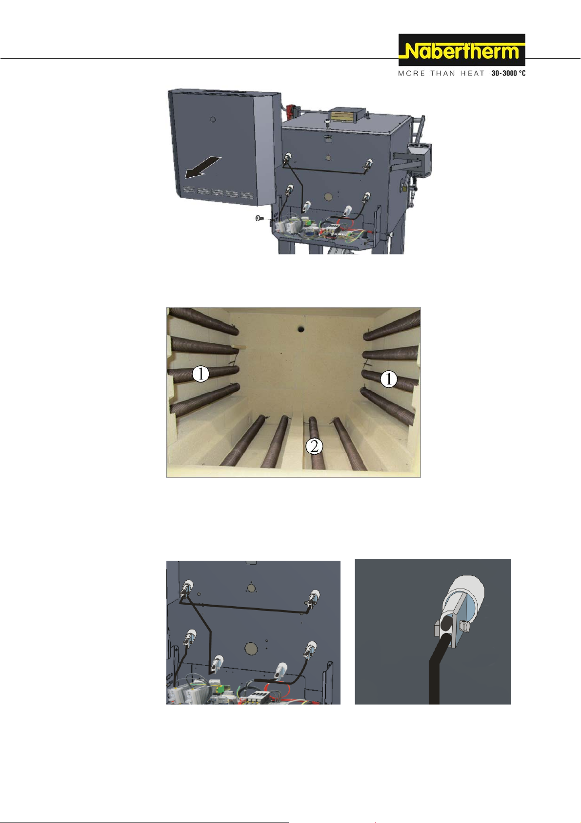
similar to picture
Fig. 35: Example: Removing Cover/s
Arrangement of the Heating Elements (depending on model)
similar to picture
1 Heating elements furnace interior
2 Heating elements (remove base plates) depending on model
Fig. 36: Example: Heating elements (depending on model)
Arrangement of the Connection Terminals (depending on model)
Fig. 37: Example: Connection terminals of the heating elements (similar to picture)
77
Page 78
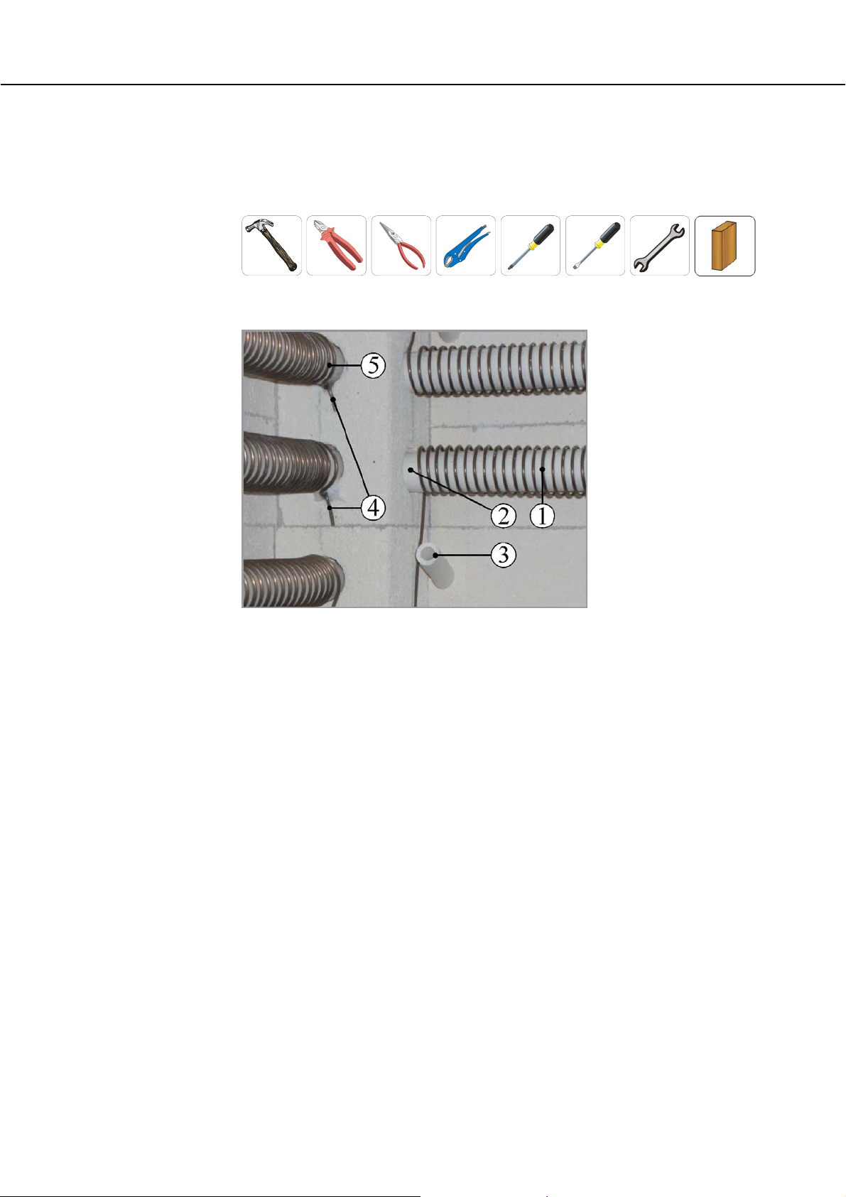
Tools Required by Customer for the Installation
The following tools are required to replace the heating elements. Hammer, cable cutter,
long-nose pliers, pipe wrench, screwdriver (depending on the age of the furnace, Phillips
screwdriver, flat-tip screwdriver, jaw wrench and a wood block to hammer in the ceramic
penetration pipes.
Replacing the Heating Elements (short description)
1 Heating element (heating coil)
2 Support tube
Fig. 38: Designation of the required attachments
similar to picture
3 Holding tube (depending on model)
4 Holding clamp/s
5 Fiber wadding
78
Page 79

7 Ceramic penetration pipe, 6 Fiber wadding
8 Connection terminal
9 Heating element end (twisted)
Fig. 39: Example: Connection terminal/s (similar to picture)
Removing the Heating Elements
Remove the protective paneling of the electrical connections.
Loosen the connection terminals at the ends of the heating coils. Replace ceramic
penetration pipe as necessary.
Draw out the existing holding clamps and ceramic tubes for holding the heating
element in place out of the masonry (old holding clamps are highly fragile. If a
holding clamp breaks, the piece still stuck in the masonry must be removed).
Remove heating coils carefully with the support tubes (Caution: older heating
elements are highly fragile)-
Installing the Heating Elements
Clean firing deposits from heating chamber, support tubes, support bricks, terminals
and ceramic penetrations.
Warning: We recommend using new support tubes, terminals and ceramic
penetration pipes (soiled support tubes/ceramic penetration pipes result in early failure
of the new heating elements).
The new heating elements have heating element ends (twisted) protected by a lug. Nip
the lugs before installation. Install the heating coil with the support tubes
Insert the holding clamps into the wall masonry. Warning: Never use the old holes for
the new holding clamps. This may result in problems with the Fi switch (if included)
Depending on the furnace model, ceramic tubes can also be installed as holders
instead of holding clamps.
Insulate the ceramic penetration pipes with a small amount of fiber wadding from
outside. Make the electric connections using the connection terminals: Hold the lower
part with a pliers and tighten the screw (6 Nm) firmly.
Recommendation: Retighten all the screws of the connection terminals of the heating
elements after one week of operation and, thereafter, once a year. Avoid placing any
stress, pressure or twist on the heating wire. If you fail to follow this instruction the
result is the immediate destruction of the sensitive heating elements.
If necessary trim any overlaying fibers to somewhat longer than one terminal width
(approx. 2-3 cm).
79
Page 80

Pos: 348 /TD/Einleitung/Technische Daten/Flansc he/ Drehmomente für Schrauben/Muttern M4_M5_M6_ M7_ M8 _ M10 - Tabelle @ 97\mod_1435573472082_51.docx @ 393604 @ @ 1
Check electrical connections and protective lines to ensure they are correctly
connected.
Screw tightening torque
Tighten power cable clamps and screws on the heating elements with a defined torque.
If this advice is not followed, the heating elements may be damaged.
Pos: 349 /TD/Transport_Montage_Inbetriebnahme/Er stinbetriebnahme/Die Bildung einer Oxidschi cht bei der Verwendung von Heizelementen - Heizwendel @ 99\ mod_1437112579759_51.docx @ 398170 @ @ 1
Thread diameter
Torque in Nm
Metric thread (M)
M 4 2.0
M 5 6.0
M 6 8.0
M 7 14.0
M 8 20.0
M 10 39.0
The formation of a layer of oxide is necessary for the correct function of the heating
element.
This procedure is for the first start-up and must be repeated after every replacement of
heating elements.
The duration of the oxidation firing can be found in the section entitled "Recommendation
for Heating the Furnace for the First Time".
Nest formation is a natural process and
requires no correction. Considerable nest
formation, however, can influence
temperature distribution.
Pos: 350 /TD/Allgemeine Hinweise (für alle Anleitungen) /Hinweis - Bei Verwendung von Begasungskästen wird ei ne Arbeitstemperatur bis zu 1100 °C (2012 °F).. . @ 123\ mod_1465290938112_51.docx @ 545676 @ @ 1
Note
If the protective gas boxes are used, a working temperature to 1100 °C (2012 °F) is
recommended; with working temperatures to 1150 °C (2102 °F) the boxes will suffer
increased wear.
80
Before
After (nest formation)
Page 81

Pos: 351 /TD/Ersatz-/Verschleißteile/Montage er folgt in umgekehrter Reihenfolge. @ 15\mod_13028585 12460_51.docx @ 115886 @ @ 1
Note
Re-install in reverse sequence.
Pos: 352 /TD/Allgemeine Hinweise (für alle Anleitungen) / Hinweis - Alle Schraub- und Steckverbindungen sind or dnungsgemäß zu überprüfen. @ 21\mod_1331807422171_5 1.docx @ 151860 @ @ 1
Pos: 353 /TD/Ersatz-/Verschleißteile/Übersc hrift - Thermoelement austauschen 1.1 @ 2\mod_118657956 9245_51.docx @ 20769 @ 2 @ 1
Note
Make sure that all screwed and plugged connections are in working order.
9.2 Replacing a Thermocouple
Pos: 354 /TD/Ersatz-/Verschleißteile/W arnung - Gefahren durch elektrischen Strom - Netzstecker ziehe n - für alle Öfen @ 3\mod_1189491390787_51.docx @ 21273 @ @ 1
Warning - Danger of Electric Shock!
Work on the electrical equipment may be done only by qualified, authorized electricians.
During work it must be ensured that the furnace and the switching equipment cannot be
activated by mistake (pull out the power plug) and that all moving parts in the furnace are
secured. Observe DGUV V3 or the corresponding national regulations in the country where
the furnace is installed. Wait until the furnace and the connected parts have cooled to room
temperature.
Pos: 355 /TD/Allgemeine Hinweise (für alle Anleitungen) / Warnung - Bei unsachgemäßer Installation ist die Funk tion und Sicherheit der Anlage nicht mehr ... @ 3\mod_1193759 200813_51.docx @ 26438 @ @ 1
Warning! General hazards!
If installed improperly, functioning and safety of the system can no longer be guaranteed.
The connection must be properly installed and put into operation by qualified personnel.
Pos: 356 /TD/Ersatz-/Verschleißteile/Vorsi cht - Beschädigung von Bauteilen! Thermoelement aus tausc hen @ 3\mod_1189492921935_51.docx @ 21312 @ @ 1
Caution - damage to components!
Thermocouples are extremely sensitive to breakage. Any strain on or rotation of the
thermocouples must be avoided. Failure to observe this rule will lead to the immediate
destruction of the sensitive thermocouples.
Pos: 357 /TD/Einleitung/Die in der Anleitung gezeig ten Abbi ldungen können abhängig von Funktion, ... Ofenmodell abweichen @ 24\mod_1337854352242_51.docx @ 161605 @ @ 1
Pos: 358 /TD/Ersatz-/Verschleißteile/Demon tage von Abdeckblechen durch umlaufende Schrauben lösen ... - Beschreibung @ 22\mod_1333008626711_51. doc x @ 153515 @ @ 1
Note
The pictures contained in the instruction manual may contain inaccuracies in terms of the
function, design and furnace model.
Use an appropriate tool to remove the screws all around the cover and keep them in a
secure place for later use. The cover must be lowered onto a soft material (such as foam
rubber). The number and position of the screws may differ from one furnace model to the
next. The furnace may look different than the picture depending on the furnace model and
additional equipment.
81
Page 82

Pos: 359 /TD/Ersatz-/Verschleißteile/Thermoe lement Rückwand demontieren - Kammerofen N 41/H - Grafik @ 32\ mod_1351080616503_51.docx @ 189090 @ @ 1
Pos: 360 /TD/Ersatz-/Verschleißteile/Thermoe lement austauschen - HT 04/16-HT 450/18-Öfen - Beschrei bung @ 22\mod_1333000959344_51.docx @ 153490 @ @ 1
Pos: 361 /TD/Ersatz-/Verschleißteile/Thermoe lement austauschen - Kammerofen N 41/H - Grafik @ 32\mod_13510 80720229_51.docx @ 189115 @ @ 1
Fig. 40: Removing the back furnace wall (similar to picture)
You can find the position and labeling of built-in thermocouples in the schematic
contained in the appendix.
First remove the two screws (A) from the thermocouple connection. Remove screw (B) and
pull out the thermocouple (C).
Insert the new thermocouple carefully into the thermal channel (C), install and connect in
reverse order. Make sure that the polarity of the electrical connections (D) is correct*).
82
A
B
Fig. 41: Removing the thermocouple/s (similar to picture)
C
Page 83

+-+
+
-
Pos: 362 /TD/Allgemeine Hinweise (für alle Anleitungen) /Hinweis - Die Anschlüsse der Verbindungsleitun gen vom Thermoelement zum Regler sind mit + und - @ 3\mod_1190123 241249_51.docx @ 21916 @ @ 1
Note
*) The connections of the connecting lines from the thermocouple to the controller are
labeled with and . It is absolutely essential to observe the correct polarity.
-
Pos: 363 /TD/Allgemeine Hinweise (für alle Anleitungen) / Hinweis - Alle Schraub- und Steckverbindungen sind or dnungsgemäß zu überprüfen. @ 21\mod_1331807422171_5 1.docx @ 151860 @ @ 1
Pos: 364 /TD/Betrieb_Bedienung/Controller/B 150/ B130/B170/C280/C290/C295/P320/Schaltplä ne/Überschrift - Elektrische Schaltpläne/Pn eumatikpläne @ 47\mod_1380029813550_51.docx @ 247718 @ 2 @ 1
to to
Note
Make sure that all screwed and plugged connections are in working order.
9.3 Electrical Schematics/Pneumatic Schematics
Pos: 365 /TD/Betrieb_Bedienung/Die mitgeliefert en Unterlagen beinhalten nicht zwangsläufig elektr ische Schaltpläne bzw. Pneuma ... @ 47\mod_1380028074616_51.docx @ 247668 @ @ 1
Note
The documents included do not always contain the electrical schematics and pneumatic
schematics.
If you need the respective schematics they can be ordered from Nabertherm Service.
Pos: 366 /TD/Service-Typenschild/Naberther m-Service @ 0\mod_1158658915997_51.docx @ 2861 @ 1 @ 1
10 Nabertherm Service
Contact Nabertherm Service at any time for maintenance and repair.
If you have any questions, problems, or requirements, contact Nabertherm GmbH. By mail,
phone or e-mail.
Mail
Nabertherm GmbH
Bahnhofstrasse 20
28865 Lilienthal/Germany
Phone or Fax
Phone: +49 (4298) 922-0
Fax: +49 (4298) 922-129
Web or E-mail
www.nabertherm.com
contact@nabertherm.de
Pos: 367 /TD/Service-Typenschild/Typenschil d gek lebt_108 x 84 mit CE @ 43\mod_1371118967603_51.docx @ 23358 0 @ @ 1
When you contact us, please have the type plate details of the furnace or controller at
hand.
Provide the following details from the type plate:
83
Page 84

Fig. 42: Example (type plate)
Pos: 368 /TD/Außerbetriebnahme_Demontage_Lagerung _Rücktransport/Überschrift - Außerbetri ebnahme, Demontage und Lagerung @ 0\mod_1167838295210_5 1.docx @ 5580 @ 1 @ 1
11 Shut-Down, Dismantling, and Storage
Pos: 369 /TD/Außerbetriebnahme_Demontage_Lagerung _Rücktransport/Außerbetriebnahme ... vom Betreiber zu ergänzen - 1 @ 0\mod_1158677947766_51.docx @ 2921 @ @ 1
To be Completed by the Operator
When the furnace is shut down, the following safety information must be observed to
prevent serious injury, damage to property, and damage to the environment.
The furnace may only be shut down by authorized, trained personnel.
The following operating materials/parts are to be disposed of by:
_________________________________________________________________
_________________________________________________________________
_________________________________________________________________
_________________________________________________________________
1
Furnace model
Serial number
2
Article number
3
Year of construction
4
Oils and other substances that are hazardous to water must be completely removed before
the furnace is dismantled for reuse or scrap.
Ensure that operating materials, lubricants, and consumables are disposed of in an
environmentally compliant manner. Regulations relating to proper waste recycling and
disposal must be observed.
The furnace may be lifted only at the intended points.
Use only the stated lifting and securing equipment to lift the furnace/parts.
Consider a total weight of ___________kg when choosing suitable lifting equipment.
For transportation, consider a permitted floor weight of at least ___________kg/m².
Before transporting the furnace, attach the following securing equipment:
_________________________________________________________________
_________________________________________________________________
_________________________________________________________________
_________________________________________________________________
Note
Read the sections on "Safety" and "Transportation"
84
Page 85

Pos: 370 /TD/Außerbetriebnahme_Demontage_Lagerung _Rücktransport/Hinweise für den Rücktranspor t d er Ofen-Anlage @ 4\mod_1202459053863_51.docx @ 30918 @ 2 @ 1
11.1 Transportation/Return Transportation
If you still have the original packaging, this is the safest way to send a furnace.
Otherwise:
Choose suitable, adequately sturdy packaging. During transportation, packages are often
stacked, bumped, or dropped; the packaging acts as external protection for your furnace.
+45 °
-5 °C
- Drain all piping and containers before transportation/return transportation
(e.g. cooling water). Pump off operating materials and di spose of properly.
- Do not subject the furnace to extreme cold or hot temperatures (direct sunlight).
Storage temperature -5 °C to 45 ° (-23 °F to 113 °F)
Humidity 5 % to 80 %, non condensing
- Place the furnace on a level floor to prevent distortion.
- Packaging and transportation may be carried out only by qualified and
authorized persons
If your furnace has transportation securing equipment (see "Transportation Securing
Equipment"), use this.
Otherwise, in general:
"Fix" and "secure" (adhesive tape) all moving parts and cushion and protect any projecting
parts against breakage.
Protect your electronic equipment against moisture and make sure that no loose packaging
material can get inside it.
Fill gaps in your packaging with soft but adequately firm material (e.g. foam mats) and
make sure that the equipment cannot slide around in the packaging.
If the goods are damaged during return transportation due to inadequate packaging
or some other breach of duty, the costs will be borne by the customer.
As a rule:
The furnace is sent without accessories, unless the technician expressly requests them.
Enclose a detailed description of the malfunction along with the furnace – this saves the
technician time and costs.
Don't forget to enclose the name and phone number of a contact in case there are any
questions.
Note
Return transportation may only be carried out according to the information given on the
packaging or in the transportation documents.
Note
Transportation and return transportation not covered by a warranty claim are paid for by
the customer.
Pos: 371 /Steuermodule/=== Seitenumbruch === @ 0\mod_11588 19844943_0.docx @ 2983 @ @ 1
85
Page 86

Pos: 372 /TD/Anhang/Überschrift - Konformitätserk lärung @ 2\mod_1186581095030_51.docx @ 20795 @ 1 @ 1
12 Declaration of Conformity
Pos: 373 /EG-Erklärungen/Kopfmodul/Konformitä tserklärung Maschinenrichtlinie @ 10\mod_12603 62199708_51.docx @ 69675 @ @ 1
EC Declaration of Conformity
Compliant with EC Directive 2006/42/EC on machinery, Annex II A
We,
Nabertherm GmbH
Bahnhofstr. 20, 28865 Lilienthal, Germany
Pos: 374 /EG-Erklärungen/Produktangaben/dass fo lgendes Produkt: @ 10\mod_1260343529474_51.doc x @ 69324 @ @ 1
hereby declare that the following product:
Pos: 375 /EG-Erklärungen/Produktangaben/N 7/H-N 11/ H-N11/HR-N17/HR-N31/H-N41/H-N61/H-N87/H @ 117\ mod_1460618526274_51.docx @ 463865 @ @ 1
Electrically Heated Chamber Furnaces
Model
Pos: 376 /EG-Erklärungen/Erklärungen/allen einsc hlägigen Bestimmungen der Richtlinie 2006/42/E G entspricht. @ 10\mod_1260357384257_51.docx @ 69527 @ @ 1
fulfills all the pertinent provisions contained in Directive 2006/42/EC.
Pos: 377 /EG-Erklärungen/Mitgeltende Richtlini en/Das bezeichnete Produkt entspricht weiterhi n a llen Bestimmungen der Richtlinien: @ 10\mod_12603435 93204_51.docx @ 69340 @ @ 1
The product named is also compliant with all the provisions of the following directives:
Pos: 378 /EG-Erklärungen/Mitgeltende Richtlini en/EG-Niederspannungsrichtlinie Nr. 2014/ 35/ EU @ 116\mod_1459500325444_51.docx @ 460798 @ @ 1
Directive 2014/35/EU for electrical equipment designed for use within certain voltage limits
Pos: 379 /EG-Erklärungen/Mitgeltende Richtlini en/EG-Richtlinie Elektromagnetische Vertr äg lichkeit Nr. 2014/30/EU @ 116\mod_145950036987 3_51. docx @ 460825 @ @ 1
Directive 2014/30/EU on electromagnetic compatibility
Pos: 380 /EG-Erklärungen/Erklärungen/Dokumen tationsverantwortliche @ 10\mod_1260355006988_5 1.docx @ 69493 @ @ 1
N 7/H N 11/H N 11/HR N 17/HR N 31/H N 41/H
N 61/H N 87/H
The signatories are authorized to compile the relevant technical documents. The address is the
stated manufacturer's address.
Pos: 381 /EG-Erklärungen/Erklärungen/Änderung des P r oduktes @ 10\mod_1260355011435_51.docx @ 69510 @ @ 1
Any change in the product not approved by the manufacturer invalidates this declaration.
Pos: 382.1 /EG-Erklärungen/Mitgeltende Normen/Fo lgende harmonisierte Normen wurden angewandt: @ 10\mo d_12 60360041778_51.docx @ 69544 @ @ 1
The following harmonized standards were applied:
Pos: 382.2 /EG-Erklärungen/Mitgeltende Normen/ Normen/DIN EN 60335-1 @ 40\mod_1366632640961_0.doc x @ 226100 @ @ 1
DIN EN 60335-1 (10.2012)
Pos: 382.3 /EG-Erklärungen/Mitgeltende Normen/ Normen/DIN EN 61000-6-1, DIN EN 61000-6-3 @ 32\mod_13515956 7282 5_0.docx @ 190568 @ @ 1
DIN EN 61000-6-1 (10.2007), DIN EN 61000-6-3 (09.2011)
Pos: 383 /EG-Erklärungen/Ort und Datum @ 0\mod_115501851365 1_0.docx @ 1093 @ @ 1
Lilienthal, 01.05.2016
Pos: 384 /EG-Erklärungen/Unterschriftkombina tionen/Unterschriften Oberschmidt/Adamek mit Unterschrift @ 65\mod_1407146497542_51.doc x @ 309030 @ @ 1
________________________ _______________________
Michael Oberschmidt Thomas Adamek
Vice President R & D Quality Management
=== Ende der Liste für Textmarke Inhalt ===
86
Page 87

87
Page 88

Headquarters: Reg: M01.0071 ENGLISCH
Nabertherm GmbH . Bahnhofstr. 20
.
28865 Lilienthal/Bremen, Germany . Tel +49 (4298) 922-0, Fax -129 . contact@nabertherm.de
.
www.nabertherm.com
 Loading...