

Page 1

Operating Instructions
Laboratory Furnaces (Muffle Furnaces)
L / LE / LT / LV / LVT -SKM -SW -HA
-> 10.2005
Original instructions
www.nabertherm.com
Made
in
Germany
Page 2

Copyright
Copyright by
Nabertherm GmbH
Bahnhofstrasse 20
28865 Lilienthal
Federal Republic of Germany
Reg: M01.0032 ENGLISCH
Rev: 2011-01
No responsibility is accepted for the correctness of this information. We
reserve the right to make technical alterations.
2
Page 3

1 Introduction ........................................................................................................................................................... 5
1.1 Product Description ........................................................................................................................................... 6
1.2 Overview of the Complete Oven ....................................................................................................................... 7
1.3 Key to the Model Names ................................................................................................................................... 9
1.4 Scope of Delivery ............................................................................................................................................ 10
2 Specifications ....................................................................................................................................................... 11
2.1 Warranty and Liability .................................................................................................................................... 16
3 Safety .................................................................................................................................................................... 17
3.1 Intended Use.................................................................................................................................................... 17
3.2 Requirements for the Oven Operator .............................................................................................................. 18
3.3 Requirements for the Operating Personnel ...................................................................................................... 19
3.4 Protective Clothing .......................................................................................................................................... 19
3.5 Basic Measures During Normal Operation ..................................................................................................... 20
3.6 Basic Measures in Case of Emergency ........................................................................................................... 20
3.6.1 What to do in an Emergency ....................................................................................................................... 20
3.7 Basic Measures for Servicing and Maintenance.............................................................................................. 21
3.8 Environmental Regulations ............................................................................................................................. 22
3.9 Explanation of the Symbols and Warnings ..................................................................................................... 23
3.10 General Risks with the Oven ........................................................................................................................... 26
4 Transportation, Installation, and Commissioning ............................................................................................ 27
4.1 Delivery ........................................................................................................................................................... 27
4.2 Unpacking ....................................................................................................................................................... 30
4.3 Transportation Securing Equipment/Packaging .............................................................................................. 31
4.4 Constructional and Connection Requirements ................................................................................................ 32
4.4.1 Installation (Oven Location) ....................................................................................................................... 32
4.5 Assembly, Installation, and Connection .......................................................................................................... 33
4.6 Assembly of a Vent ......................................................................................................................................... 33
4.6.1 Waste Gas System ...................................................................................................................................... 35
4.6.2 Connecting the Oven to the Power Supply ................................................................................................. 36
4.6.3 Insertion of the Base Plate .......................................................................................................................... 39
4.7 Commissioning ............................................................................................................................................... 41
4.8 Recommendations for Heating the Oven for the First Time ........................................................................... 41
4.9 Loading/charging ............................................................................................................................................ 42
5 Operation ............................................................................................................................................................. 44
5.1 Operating Controller B 180/P 330 ................................................................................................................... 44
5.2 Operating Controller R 6 ................................................................................................................................. 45
5.3 Over-Temperature Limit Controller with Manual Reset and Adjustable Cut-Off Temperature ..................... 46
5.4 Air Inflow Lever ............................................................................................................................................. 47
6 Servicing, Cleaning, and Maintenance .............................................................................................................. 48
6.1 Shutting the system down for maintenance ..................................................................................................... 49
6.2 Regular Maintenance of the Oven ................................................................................................................... 50
6.3 Operating and Auxiliary Materials .................................................................................................................. 50
6.4 Cleaning Products ........................................................................................................................................... 50
7 Faults .................................................................................................................................................................... 52
3
Page 4

7.1 Replacing a Fuse ............................................................................................................................................. 53
7.2 Separate the Snap-In Coupling (Plug) from the Furnace Housing .................................................................. 54
8 Spare Parts/Wearing Parts ................................................................................................................................. 55
9 Nabertherm Service ............................................................................................................................................ 56
10 Electrical Connections (Circuit Diagram) ......................................................................................................... 56
11 Shut-Down, Dismantling, and Storage............................................................................................................... 57
11.1 Environmental Regulations ............................................................................................................................. 57
11.2 Transportation/Return Transportation ............................................................................................................. 58
12 Declaration of Conformity .................................................................................................................................. 59
4
Page 5
Pos: 1 /TD/Einleitung/Überschrift - Einleitung 1 @ 0\ mod_1167823212238_51.doc @ 5139 @ 1 @ 1
1 Introduction
Pos: 2 /TD/Einleitung/Öfen @ 0\mod_1158157227533_51. d oc @ 2084 @ @ 1
Dear Customer,
Thank you for choosing a quality product from Nabertherm GmbH.
You can be proud that you have chosen an oven which has been especially tailored to suit
your manufacturing and production conditions.
This product is characterized by
professional workmanship
high performance due to its high efficiency
high-quality insulation
low power consumption
low noise level
simple installation
easy to maintain
high availability of spare parts
Your Nabertherm Team
Pos: 3 /=== Seitenumbruch === @ 0\mod_1158819844943_0.doc @ 2983 @ @ 1
Note
These documents are intended only for buyers of our products and may not be copied or
disclosed to third parties without our written consent.
(Law governing copyright and associated protective rights, German Copyright Law from
Sept. 9, 1965)
Protective Rights
Nabertherm GmbH owns all rights to drawings, other documents and authorizations, also in
case of applications for protective rights.
Note
All the figures in the instructions have a descriptive character; in other words, they do not
represent the exact details of the oven.
5
Page 6

Pos: 4 /TD/Einleitung/Produktbeschreibung/Öfen/ Überschrift - Produktbeschreibung 1.1 @ 0\mod_116 7821943807_51.doc @ 5103 @ 2 @ 1
1.1 Product Description
Pos: 5 /TD/Einleitung/Produktbeschreibung/Öfen/ Laborofen L-LE-L(T)-LV(T)-SKM-SW-HA - Pr oduktbeschreibung @ 14\mod_1299596880427_51.doc @ 113276 @ @ 1
These laboratory furnaces are a high-quality product which will give you many
years of reliable service if they are properly cared for and maintained. One basic
prerequisite is that the furnace is used the way it was designed to be used.
During development and production a high priority was placed on safety,
functionality and economy.
Laboratory Furnaces are attractive thanks to their many advantages. These
furnaces are all-rounders for research and laboratory applications. They are made
from expertly finished, high-quality materials and are easy to operate. These
furnaces are optimally designed for incinerating and heat treatment. The very best
insulation materials permit energy-saving operation and fast heating times thanks
to low heat storage and thermal conductivity. Laboratory furnaces attain furnace
chamber temperatures of max. 1100 °C (2012 °F), 1200 °C (2192 °F) or 1300 °C
(2372 °F).
Other characteristics of this product are:
All the models have a high-quality, multi-layered and energy-saving thermal
Double-wall housing means low outer temperatures and solid stability. All
Good temperature uniformity provided by special air supply and exhaust system
There are furnaces with drop-down doors or lift doors
Ceramic heating plates with integrated heating wire, protected against splattering
Model L/LT …/…/SW with scale and software (Controltherm MV) for annealing
All the models are equipped with a controller which provides considerable safety
Additional Equipment
Vent, vent with fan or catalytic converter.
Over-temperature limit controller with adjustable shut-down temperature for
Manual or automatic protective gas system Protective gas connection on the back
Digital interface RS 422, for example, for process control and documentation
Base plates and catch basins to protect of the furnace and to enable easy charging
Rectangular container, stackable for charging on several levels
Pos: 6 /=== Seitenumbruch === @ 0\mod_1158819844943_0.doc @ 2983 @ @ 1
insulation
furnaces have housings made of textured stainless steel sheet.
for models LV/LVT .../… and LT …/…HA. For models LV/LVT .../… the system
delivers more than 6 air changes a minute. The incoming air is pre-heated, so that
a good temperature uniformity is ensured.
and exhaust-air for models L/LT …/… and LV/LVT .../…
loss specifications
against operator mistakes. The furnace chamber temperature is measured and
regulated by a long-life thermocouple (NiCr-Ni Tmax < 1100 °C or PtRh-Pt Tmax
> 1100 °C).
thermal protective class 2 as specified in EN 60519-2 to protect the furnace and
the ware against overheating.
side of the furnace
provided by Controltherm MV software package.
6
Page 7
Pos: 7 /TD/Einleitung/Lieferumfang/Öfen/Übersc hrift - Gesamtübersicht der Anlage @ 1\mod_11743026 3699 2_51.doc @ 11332 @ 2 @ 1
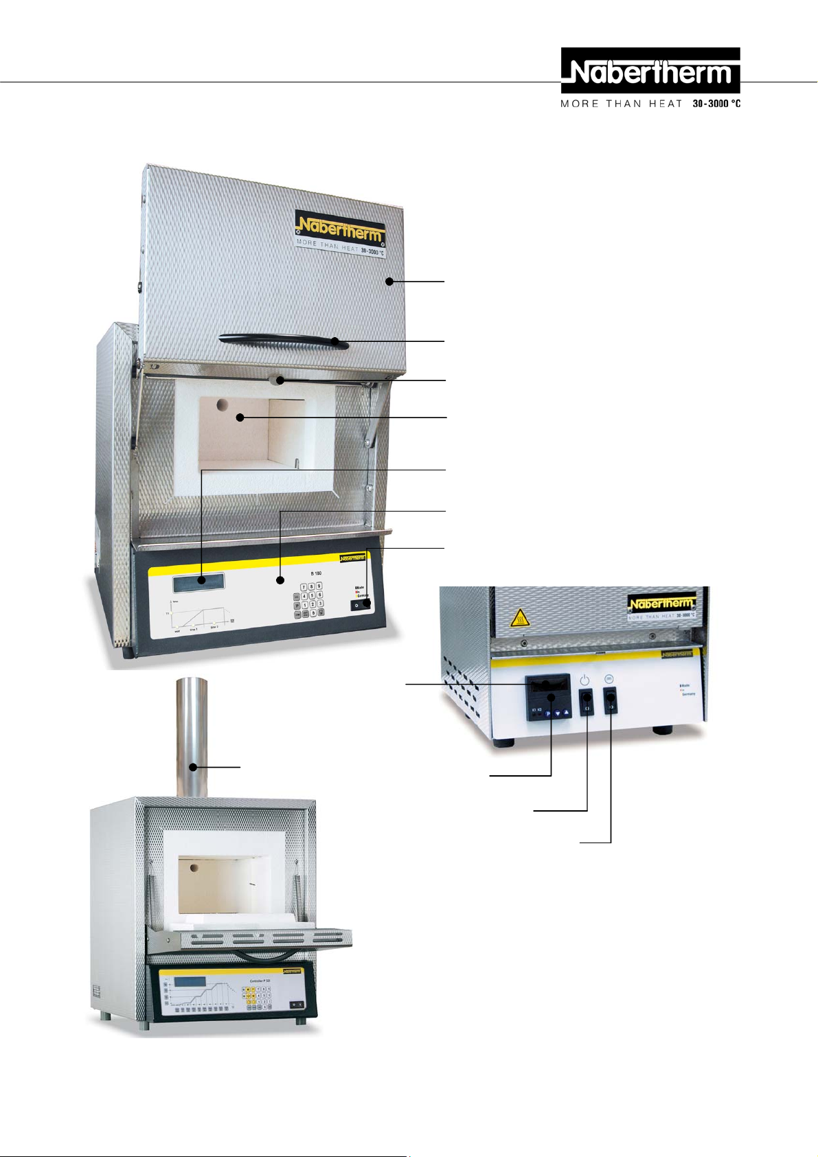
1.2 Overview of the Complete Oven
Pos: 8 /TD/Einleitung/Lieferumfang/Öfen/Gesa mtübersicht Laborofen L-LE-L(T)-LV(T)-SKM-SW -HA @ 14\mod_1295003962965_51.doc @ 111859 @ @ 1
Furnace door
Handle
Air for the regulation of fresh air
Furnace chamber
Display
Exhaust-air system
Display
Controller
Power switch (ON/OFF)
Controller
Power switch (ON/OFF)
Heating (ON/OFF)
7
Page 8
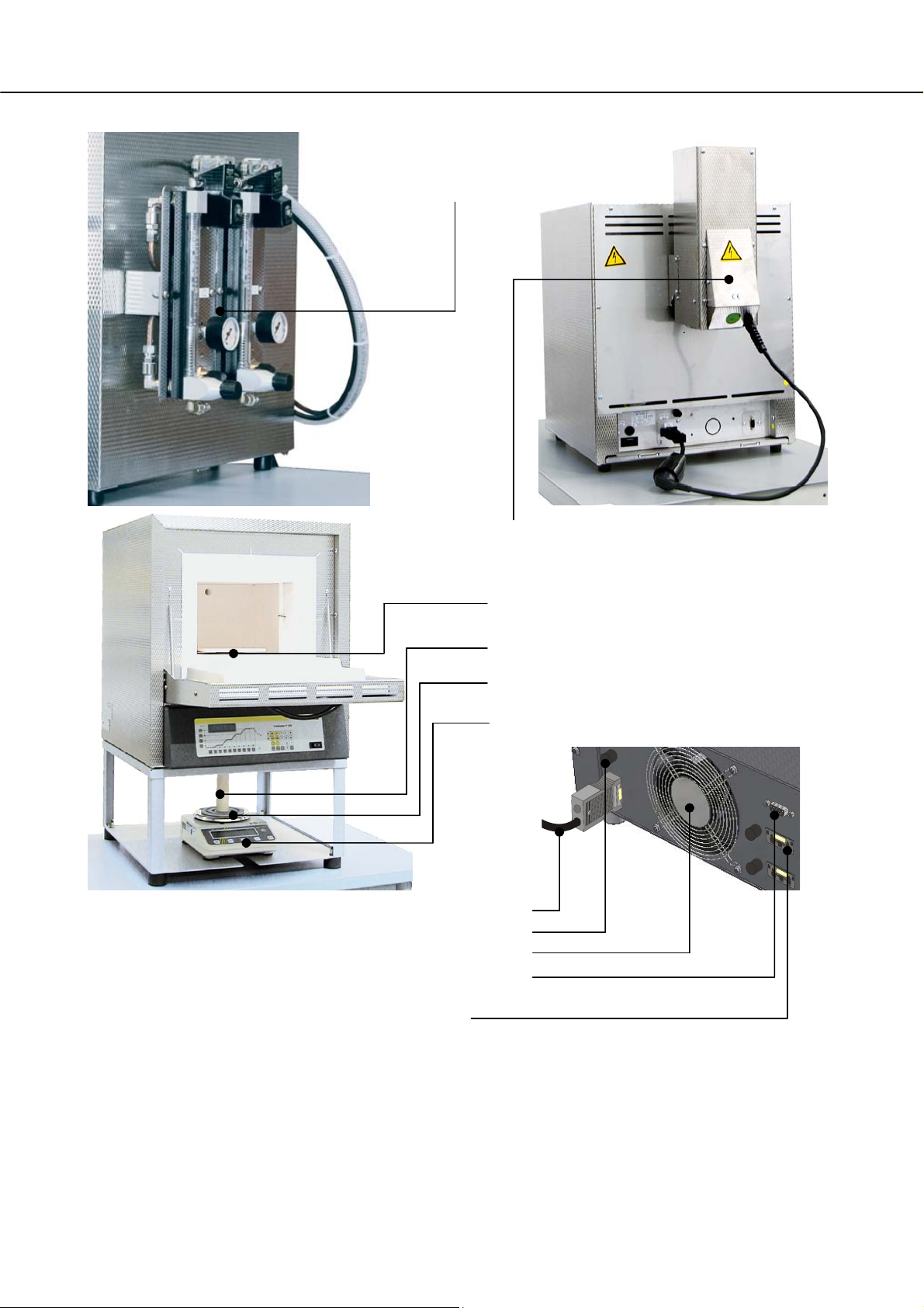
Gas supply system
(additional
equipment)
Vent, vent with fan or catalytic converter
(accessories)
Support plate in the furnace
chamber
Ceramic die
Support die
Scale
Backup power connection
(lock for backup power connection)
for example, for vent with fan or gas supply system (additional equipment)
Fig. 1: Example: Complete overview of various laboratory furnaces
Pos: 9 /=== Seitenumbruch === @ 0\mod_1158819844943_0.doc @ 2983 @ @ 1
Digital interface RS 422 (option)
Power line
Lock
Switchgear fan
8
Page 9
Pos: 10 /TD/Einleitung/Produktbeschreibung/ Öfen/Überschrift - Entschlüsselung der Modellbez ei chnung @ 2\mod_1184245078907_51.doc @ 19775 @ 2 @ 1
1.3 Key to the Model Names
Pos: 11 /TD/Einleitung/Produktbeschreibung/ Öfen/Entschlüssellung der Modellbezeichnung Labor ofen L-LE-L(T)-LV(T)-SKM-SW-HA @ 14\mod_1299593606 987_51.doc @ 113253 @ @ 1
Example Explanation
LT 9/11SKM
LT 9/11SKM
LT 9/11SKM
LT 9/11SKM
L = Laboratory furnace with drop-down door
LE = Laboratory furnace economy series
LT = Laboratory furnace with lift door
LV = Laboratory incinerator with drop-down door
LVT = Laboratory incinerator with lift door
1 = 1-liter furnace chamber (volume in L)
2 = 2-liter furnace chamber (volume in L)
3 = 3-liter furnace chamber (volume in L)
4 = 4-liter furnace chamber (volume in L)
5 = 5-liter furnace chamber (volume in L)
6 = 6-liter furnace chamber (volume in L)
9 = 9-liter furnace chamber (volume in L)
14 = 14-liter furnace chamber (volume in L)
15 = 15-liter furnace chamber (volume in L)
24 = 24-liter furnace chamber (volume in L)
40 = 40-liter furnace chamber (volume in L)
11 = Tmax 1100 °C (2012 °F)
12 = Tmax 1200 °C (2192 °F)
13 = Tmax 1300 °C (2372 °F)
HA = Laboratory furnace with recirculating air fan in the back wall
SKM = Furnace chamber made of ceramic muffle
SW = Scale furnace with support frame and scale
Pos: 12 /=== Seitenumbruch === @ 0\mod_1158819844943_0.doc @ 2983 @ @ 1
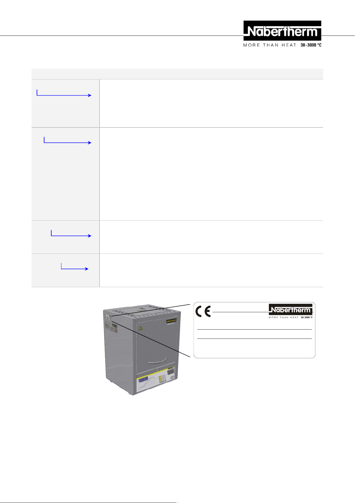
LT 9/11SKM
LC011H6SN 1100 °C 2011
230 V 1/N/PE~ 15.2 A 50/60 Hz 3.5 kW
www.nabertherm.de Made in Germany
Fig. 2: Example: Model designation (type plate)
SN xxxxxx
9
Page 10
Pos: 13 /TD/Einleitung/Lieferumfang/Öfen/Über schrift - Lieferumfang @ 0\mod_1167822508130_51. doc @ 5112 @ 2 @ 1
1.4 Scope of Delivery
Pos: 14 /TD/Einleitung/Lieferumfang/Öfen/Labor ofen L-LE-L(T)-LV(T)-SKM-SW-HA - Liefer umfang @ 14\mod_1299662508331_51.doc @ 113310 @ @ 1
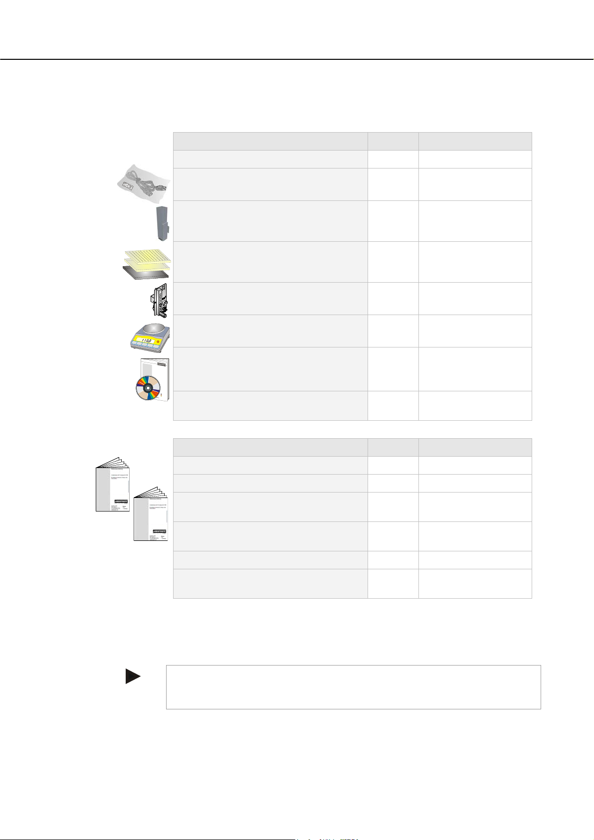
The scope of delivery includes:
Furnace components Quantity Comment
Laboratory furnace 1) 1 x Nabertherm GmbH
Power cable 1)
1 x Nabertherm GmbH
Vent ) 2)
1 x
Vent with fan 1) 2)
Catalytic converter 1) 2)
Ceramic ribbed plate
4)
Ceramic ceramic catch basin
Steel catch basin
Gas supply system 2)
1 x Nabertherm GmbH
Scale 2)
1 x Nabertherm GmbH
Process documentation
B
e
t
r
e
i
b
s
a
n
l
e
i
t
u
n
g
Controltherm MV software package 1) 2)
P
r
o
z
e
s
s
d
o
k
u
m
e
n
t
a
t
o
i
n
C
o
n
t
o
r
h
t
l
e
r
m
M
V
1 x Nabertherm GmbH
M
a
d
e
i
n
G
e
r
m
a
n
y
Other components, variable depending
on the particular furnace
- - - Consult the shipping
papers
Pos: 15 /=== Seitenumbruch === @ 0\mod_1158819844943_0.doc @ 2983 @ @ 1
Document type Quantity Comment
Instruction Manual Laboratory Furnace 1) 1 x Nabertherm GmbH
Operating Instructions for Controller 1) 1 x Nabertherm GmbH
Operating Instructions
1 x Nabertherm GmbH
gas supply system 1)
Operating Instructions
1 x Nabertherm GmbH
Controltherm MV software package 1)
Other documents, variable depending on
- - -
the particular furnace
1) = in scope of delivery depends on design/furnace model
2) = in scope of delivery depend on need, see shipping papers
3) = quantity depends on furnace model
4) = quantity depends on on need, see shipping papers
Caution
Make sure that all documents are carefully stored. All the functions of this furnace
were tested during manufacturing and prior to shipping.
10
Page 11
Pos: 16 /TD/Einleitung/Technische Daten/Öfen/ Üb er schrift - Technische Daten - mit Hinweis @ 0\mod_1167822840 737_51.doc @ 5121 @ 1 @ 1
2 Specifications
Pos: 17 /TD/Einleitung/Technische Daten/Öfen/ Mo de ll Muffelofen Klapptür -Tabelle für L 3/11 - L 40/11 bis L 1/ 12 - L 40/12 @ 14\mod_1294910652628_51.doc @ 111513 @ @ 1
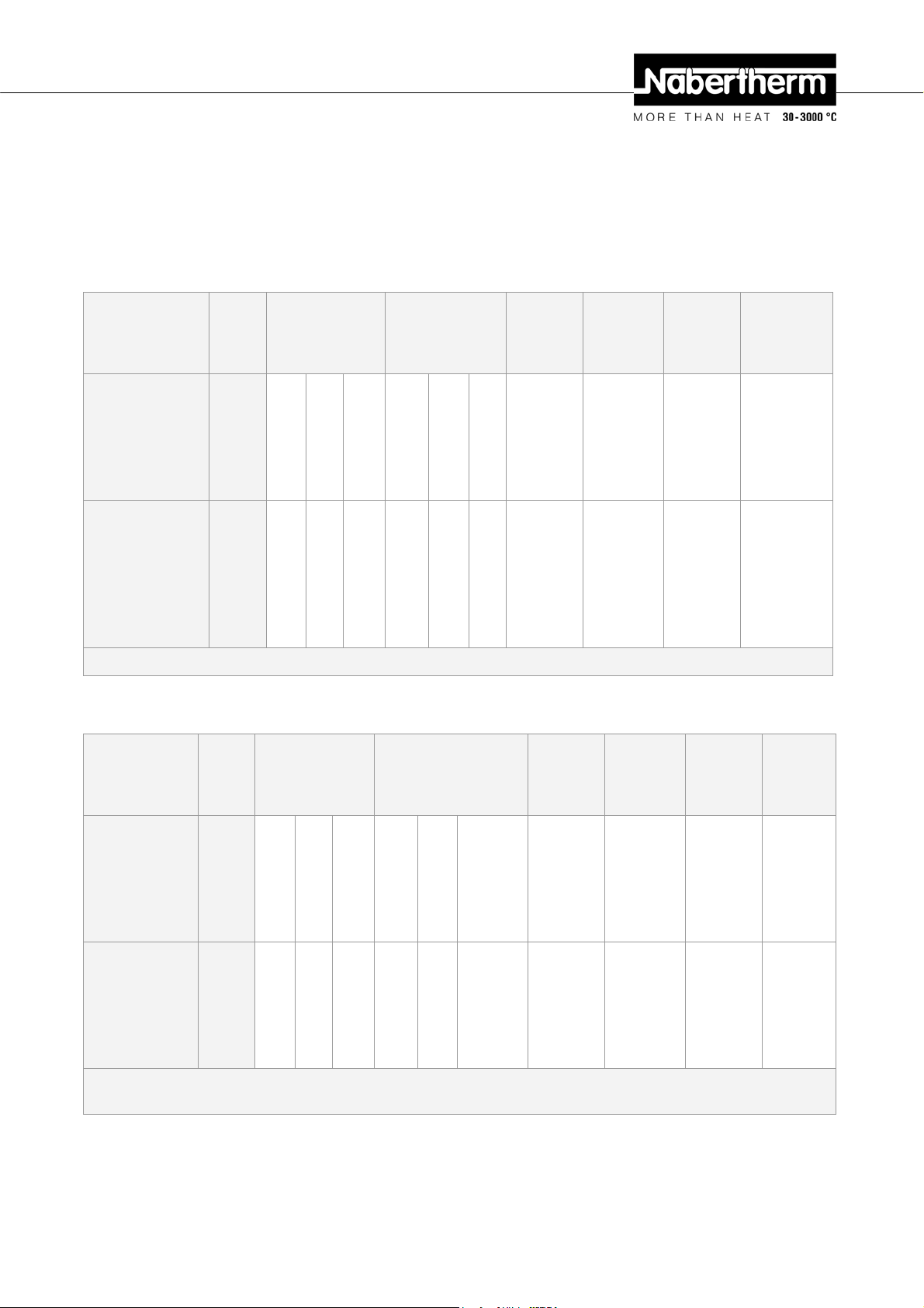
Muffle Furnace
Electrical specifications are on the type plate located on the side of the oven.
Model
Drop-Down Door
Tmax
°C
Dimensions
Interior in mm
w d h
Dimensions
Outer in mm
W D
Volume
in l
Capacity
kW max.
Weight
kg
Minutes
to
Tmax 1)
H
L 3/11 1100 160 140 100 380 370 420 3 1.2 20 60
L 5/11 1100 200 170 130 440 470 520 5 2.4 35 60
L 9/11 1100 230 240 170 480 550 570 9 3.0 45 75
L 15/11 1100 230 340 170 480 650 570 15 3.6 55 90
L 24/11 1100 280 340 250 560 660 650 24 4.5 75 95
L 40/11 1100 320 490 250 600 790 650 40 6.0 95 95
L 1/12 1200 90 115 110 250 265 340 1 1.5 10 25
L 3/12 1200 160 140 100 380 370 420 3 1.2 20 75
L 5/12 1200 200 170 130 440 470 520 5 2.4 35 75
L 9/12 1200 230 240 170 480 550 570 9 3.0 45 90
L 15/12 1200 230 340 170 480 650 570 15 3.6 55 105
L 24/12 1200 280 340 250 560 660 650 24 4.5 75 110
L 40/12 1200 320 490 250 600 790 650 40 6.0 95 110
1) = for connection to 230 V 1/N/PE or 400 V 3/N/PE
Pos: 18 /TD/Einleitung/Technische Daten/Öfen/ Mo de ll Muffelofen Hubtür -Tabelle für LT 3/11 - LT 40/11 bis LT 3/12 - LT 40/ 12 @ 14\mod_1294933924209_51.doc @ 111553 @ @ 1
Muffle Furnace
Model
Lift Door
Tmax
°C
Dimensions
Interior in mm
w d
Dimensions
Outer in mm
W D H
Volume
in l
Capacity
kW max.
Weight
kg
Minutes
to
Tmax 1)
h
LT 3/11 1100 160 140 100 380 370 420+165 3 1.2 20 60
LT 5/11 1100 200 170 130 440 470 520+220 5 2.4 35 60
LT 9/11 1100 230 240 170 480 550 570+290 9 3.0 45 75
LT 15/11 1100 230 340 170 480 650 570+290 15 3.6 55 90
LT 24/11 1100 280 340 250 560 660 650+335 24 4.5 75 95
LT 40/11 1100 320 490 250 600 790 650+335 40 6.0 95 95
LT 3/12 1200 160 140 100 380 370 420+165 3 1.2 20 75
LT 5/12 1200 200 170 130 440 470 520+220 5 2.4 35 75
LT 9/12 1200 230 240 170 480 550 570+290 9 3.0 45 90
LT 15/12 1200 230 340 170 480 650 570+290 15 3.6 55 105
LT 24/12 1200 280 340 250 560 660 650+335 24 4.5 75 110
LT 40/12 1200 320 490 250 600 790 650+335 40 6.0 95 110
1) = for connection to 230 V 1/N/PE or 400 V 3/N/PE
2) = incl. opened lift door
Pos: 19 /=== Seitenumbruch === @ 0\mod_1158819844943_0.doc @ 2983 @ @ 1
11
Page 12

Pos: 20 /TD/Einleitung/Technische Daten/Öfen/ Mo de ll Muffelofen Klapptür -Tabelle für L 5/13 - L 15/13 @ 14\ mod_12 9499 1083275_51.doc @ 111629 @ @ 1
Muffle Furnace
Model
Drop-Down
Door
Tmax
°C
Dimensions
Interior in mm
w d
h
Dimensions
Outer in mm
W D
H
Volume
in l
Capacity
kW max.
Weight
kg
Minutes
to
Tmax 1)
L 5/13 1300 200 170 130 440 470 520 5 2.4 45 45
L 9/13 1300 230 240 170 480 550 570 9 3.0 50 50
L 15/13 1300 230 340 170 480 650 570 15 3.6 60 60
1) = for connection to 230 V 1/N/PE or 400 V 3/N/PE
Pos: 21 /TD/Einleitung/Technische Daten/Öfen/ Mo de ll Muffelofen Hubtür -Tabelle für LT 5/13 - LT 15/13 @ 14\mod_12949 91040209_51.doc @ 111583 @ @ 1
Muffle Furnace
Model
Lift Door
Tmax
°C
Dimensions
Interior in mm
w d
Dimensions
Outer in mm
W D H
Volume
in l
Capacity
kW max.
Weight
kg
Minutes
to
Tmax 1)
h
LT 5/13 1300 200 170 130 440 470 520+220 5 2.4 42 45
LT 9/13 1300 230 240 170 480 550 570+290 9 3.0 60 50
LT 15/13 1300 230 340 170 480 650 570+290 15 3.6 70 60
1) = for connection to 230 V 1/N/PE or 400 V 3/N/PE
2) = incl. opened lift door
Pos: 22 /TD/Einleitung/Technische Daten/Öfen/ Mo de ll Kompakt-Muffelofen Klapptür -Tabelle für LE 1/ 11 - LE 14/11 @ 14\mod_1294992044264_51.doc @ 111652 @ @ 1
Compact Muffle Furnace
Model
Drop-Down
Door
Tmax
°C
Dimensions
Interior in mm
w d
h
Dimensions
Outer in mm
W D
H
Volume
in l
Capacity
kW max.
Weight
kg
Minutes
to
Tmax 1)
LE 1/11 1100 90 115 110 250 265 340 1 1.5 10 10
LE 2/11 1100 110 180 110 275 380 350 2 1.8 10 25
LE 4/11 1100 170 200 170 335 400 410 4 1.8 15 35
LE 6/11 1100 170 200 170 510 400 320 6 1.8 18 35
LE 14/11 1100 220 300 220 555 500 370 14 2.9 25 40
1) = for connection to 230 V 1/N/PE or 400 V 3/N/PE
Pos: 23 /TD/Einleitung/Technische Daten/Öfen/ Mo de ll Veraschungsofen Klapptür -Tabelle für LV 3/11 - LV 15/ 11 @ 14\mod_1294992766140_51.doc @ 111675 @ @ 1
Incinerator
Model
Drop-Down
Door
Tmax
°C
Dimensions
Interior in mm
w d
h
Dimensions
Outer in mm
W D
Hb+2)
Volume
in l
Capacity
kW max.
Weight
kg
Minutes
to
Tmax 1)
LV 3/11 1100 160 140 100 380 370 750 3 1.2 20 120
LV 5/11 1100 200 170 130 440 470 850 5 2.4 35 120
LV 9/11 1100 230 240 170 480 550 900 9 3.0 45 120
LV 15/11 1100 230 340 170 480 650 900 15 3.6 55 120
1) = for connection to 230 V 1/N/PE or 400 V 3/N/PE
2) = incl. exhaust air pipe (Ø 80 mm)
Pos: 24 /=== Seitenumbruch === @ 0\mod_1158819844943_0.doc @ 2983 @ @ 1
12
Page 13

Pos: 25 /TD/Einleitung/Technische Daten/Öfen/ Mo de ll Veraschungsofen Hubtür -Tabelle für LVT 3/11 - LVT 15/11 @ 14\ mod_1294992895007_51.doc @ 111698 @ @ 1
Incinerator
Model
Lift Door
Tmax
°C
Dimensions
Interior in mm
w d
Dimensions
Outer in mm
W D Hb+2)
Volume
in l
Capacity
kW max.
Weight
kg
Minutes
to
Tmax 1)
h
LVT 3/11 1100 160 140 100 380 370 750 3 1.2 20 120
LVT 5/11 1100 200 170 130 440 470 850 5 2.4 35 120
LVT 9/11 1100 230 240 170 480 550 900 9 3.0 45 120
LVT 15/11 1100 230 340 170 480 650 900 15 3.6 55 120
1) = for connection to 230 V 1/N/PE or 400 V 3/N/PE
2) = incl. exhaust air pipe (Ø 80 mm)
Pos: 26 /TD/Einleitung/Technische Daten/Öfen/ Mo de ll Muffelofen mit Keramikmuffel Klapptür/Hubtür -Tabelle für L 9/11/SKM - LT 9/11/SKM @ 14\mod_1294994910658 _51. doc @ 111721 @ @ 1
Muffle Furnace
Model
Drop-Down
Door/
Lift Door
Tmax
°C
Dimensions
Interior in mm
w d
h
Dimensions
Outer in mm
W D
H+Ha 2)
Volume
in l
Capacity
kW max.
Weight
kg
Minutes
to
Tmax 1)
L 9/11/SKM 1100 230 240 170 480 550 570 9 3.0 50 90
LT
1100 230 240 170 480 550 570+290 9 3.0 50 90
9/11/SKM
1) = for connection to 230 V 1/N/PE or 400 V 3/N/PE
2) = incl. opened lift door
Pos: 27 /TD/Einleitung/Technische Daten/Öfen/ Mo de ll Muffelofen mit Klapptür und Waage -Tabelle für L 9/11/ SW - L 9/12/SW @ 14\mod_1294995752712_51.doc @ 111744 @ @ 1
Muffle Furnace
Model
Drop-Down
Door
Tmax
°C
Dimensions
Interior in mm
w d
Dimensions
Outer in mm
W D H
Volume
in l
Capacity
kW max.
Weight
kg
Minutes
to
Tmax 1)
h
L 9/11/SW 1100 230 240 170 480 550 800 9 3.0 55 75
L 9/12/SW 1200 230 240 170 480 550 800 9 3.0 55 90
1) = for connection to 230 V 1/N/PE or 400 V 3/N/PE
Pos: 28 /TD/Einleitung/Technische Daten/Öfen/ Mo de ll Muffelofen mit Hubtür und Waage -Tabelle für LT 9/11/SW - LT 9/12/SW @ 14\mod_1294996314888_51.doc @ 111767 @ @ 1
Muffle Furnace
Model
Drop-Down
Door
Tmax
°C
Dimensions
Interior in mm
w d
Dimensions
Outer in mm
W D H
Volume
in l
Capacity
kW max.
Weight
kg
Minutes
to
Tmax 1)
h
LT 9/11/SW 1100 230 240 170 480 550 800+290 9 3.0 55 75
LT 9/12/SW 1200 230 240 170 480 550 800+290 9 3.0 55 90
1) = for connection to 230 V 1/N/PE or 400 V 3/N/PE
2) = incl. opened lift door
13
Page 14
Pos: 29 /TD/Einleitung/Technische Daten/Öfen/ Mo de ll Waage für Muffelofen L/LT 9/11-12/SW -Tabelle für EW -1500/3000/6000 @ 14\mod_1294996701851_51.doc @ 111790 @ @ 1
Scale
Type Readability
in g
Weight Range
in g
Stamp Weight
in g
Calibratio
n Value
in g
Minimum
Load
in g
EW-1500 0.01 1500 incl. stamp 850 0.1 0.5
EW-3000 0.01 1500 incl. stamp 850 0.1 0.5
EW-6000 0.10 1500 incl. stamp 850 1.0 5.0
Pos: 30 /TD/Einleitung/Technische Daten/Öfen/ Mo de ll Muffelofen Hubtür -Tabelle für LT 5/11HA - LT 15/11HA @ 14\ mod_ 1294 997879629_51.doc @ 111813 @ @ 1
Muffle Furnace
Model
Lift Door
Tmax
°C
Dimensions
Interior in mm
w d
Dimensions
Outer in mm
W D H
Volume
in l
Capacity
kW max.
Weight
kg
Minutes
to
Tmax 1)
h
LT 5/11HA 1100 200 160 130 440 470 520+220 5 2.4 36 60
LT 9/11HA 1100 230 230 170 480 550 570+290 9 3.0 46 60
LT 15/11HA 1100 230 330 170 480 650 570+290 15 3.6 56 75
1) = for connection to 230 V 1/N/PE or 400 V 3/N/PE
2) = incl. opened lift door
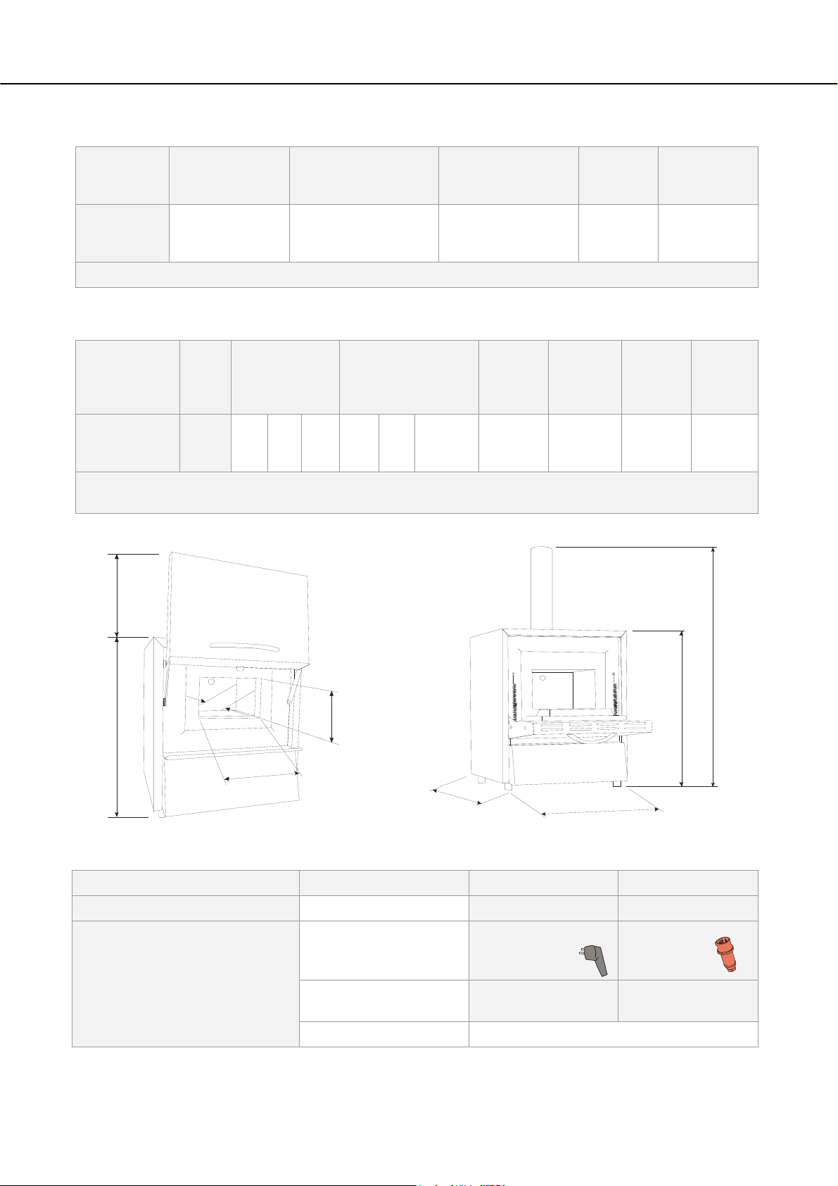
Pos: 31 /TD/Einleitung/Technische Daten/Öfen/ Mo de ll-Tabelle für Laboröfen L-LE-L(T)-LV(T)-SKM- SW -HA - Grafik - 1 @ 14\mod_1300087573327_51.doc @ 113363 @ @ 1
Ha
H
d
h
Hb
H
w
D
W
Fig. 3: Dimensions
Pos: 32 /TD/Einleitung/Technische Daten/Öfen/ Tabe lle für Laboröfen L/LT/LE/LV/LVT/ - Öfen - 1 @ 14\mod_1295001 050844_51.doc @ 111836 @ @ 1
Electrical connection
Model:
Power plug
1-phase: (1 N/PE) 3-phase: (3 N/PE)
to 3.6 kW from 4.5 kW
Protective contact plug
(with snap-in socket)
CEE plug
Voltage:
110 V – 240 V
380 V – 480 V
220 V – 240 V
14
Frequency: 50 or 60 Hz
Page 15

Thermal protection class
Protective type
Ambient conditions for electrical
equipment
Pos: 33 /TD/Einleitung/Technische Daten/Öfen/ Tabe lle Dauerschalldruckpegel < 80 dB(A) - 2 @ 1\mod_1170750985 488_51.doc @ 8913 @ @ 1
Emissions
Pos: 34 /=== Seitenumbruch === @ 0\mod_1158819844943_0.doc @ 2983 @ @ 1
Heating output in kW: see section "Specifications" or type plate on the
furnace
Furnaces:
as specified in DIN EN 60519-2
without safety controller Class 0
Furnaces: IP20
Temperature: Humidity: +5 °C to + 40 °C max. 80 % not
condensing
Continuous sound pressure
< 80 dB(A)
level:
15
Page 16

Pos: 35 /TD/Einleitung/Gewährleistung_Haftu ng/ Überschrift - Gewährleistung und Haftung 1.1 @ 0\mod_11 67822979492_51.doc @ 5130 @ 2 @ 1
2.1 Warranty and Liability
Pos: 36 /TD/Einleitung/Gewährleistung_Haftung/ Öfen und Schaltanlagen - Gewährleistung und Haftung @ 0\m od_1 157536440972_51.doc @ 1569 @ @ 1
As regards warranty and liability, the normal Nabertherm warranty terms apply,
unless individual terms and conditions have been agreed. However, the following
conditions also apply:
Warranty and liability claims for personal injury or damage to property shall be excluded if
they are attributable to one or more of the following causes:
Everyone involved in operation, installation, maintenance, or repair of the oven
must have read and understood the operating instructions. No liability will be
accepted for damage or disruptions to operation resulting from non-compliance
with the operating instructions.
Not using the oven as intended,
Improper installation, start-up, operation, or maintenance of the oven,
Operation of the oven with defective safety equipment or improperly installed or
non-functioning safety and protective equipment,
Not observing the references in the operating instructions to transportation,
storage, installation, start-up, operation, maintenance, or equipping the oven,
Making unauthorized changes to the oven,
Making unauthorized changes to the operating parameters,
Making unauthorized changes to the parameterization, the settings, or the program,
Original parts and accessories are designed especially for Nabertherm ovens.
Replace parts only with original Nabertherm parts. Otherwise the warranty will be
void. Nabertherm accepts absolutely no liability for damage caused by using parts
that are not original Nabertherm parts.
Catastrophes due to third-party causes and force majeure.
Pos: 37 /=== Seitenumbruch === @ 0\mod_1158819844943_0.doc @ 2983 @ @ 1
§
16
Page 17
Pos: 38 /TD/Sicherheit/Überschrift - Sicher heit @ 0\mod_1158843961540_51.doc @ 3103 @ 1 @ 1
3 Safety
Pos: 39 /TD/Sicherheit/Überschrift - Bestimmung sge mäße Verwendung @ 0\mod_1167823503921_51.doc @ 5148 @ 2 @ 1
3.1 Intended Use
Pos: 40 /TD/Sicherheit/Bestimmungsgemäße Verwendun g LHT-Hochtemperaturöfen (Tischmodell) @ 2\mod_118 234 7443948_51.doc @ 18724 @ @ 1
Safety
This Nabertherm system was designed and manufactured after careful selection of the
harmonized standards to be observed as well as other technical specifications. It therefore
corresponds to the state of the art, ensuring the highest possible degree of safety.
Only materials with known characteristics and melting temperatures may be used. Check
the material safety data sheets if necessary.
Use of the furnace for any other purpose whatsoever such as processing
products other than those intended or handling hazardous substances or
substances posing a health hazard constitutes improper use and must be
agreed upon with Nabertherm in writing.
Whether or not the materials used in the furnace can potentially corrode or destroy
the insulation or heating elements must be ascertained.
For furnaces with over-temperature limit controllers, the cutoff temperature must be set to
prevent overheating of the material.
Modifications to system equipment must be agreed upon with
Nabertherm in writing. It is not permitted to remove, bypass, or shut down safety devices.
The installation instructions and safety guidelines must be observed. Otherwise, the furnace
will not be considered as being used as designated, and all claims against Nabertherm
GmbH will be void.
Opening the furnace when hot (temperature greater than 200/392 °C/°F) can lead to
accelerated wear of the following components: insulation, heating elements, and furnace
housing.
Operating with power sources, products, operating equipment, additives,
etc. that are subject to the Ordinance on Hazardous Substances or cause
risks to the health of operating personnel in any way is not permitted.
Pos: 41 /TD/Allgemeine Hinweise (für alle Anleitungen) /Hinweis - Dieser Ofen verfügt über keine Sicherheit stechnik für Prozesse, in denen zündfähige Gem @ 8\mod_123 5038699771_51.doc @ 51483 @ @ 1
Pos: 42 /TD/Allgemeine Hinweise (für alle Anleitungen) /Hinweis - Dieses Produkt entspricht nicht der ATEX- Richtlinie und darf nicht ... @ 2\mod_1184228756893_5 1. doc @ 19686 @ @ 1
- This furnace is designed for commercial use. The furnace must not be used
for heating food, animals, wood, grain, etc.
- The furnace must not be used as a workplace heater.
- Do not use the furnace to melt ice or similar materials.
- Do not use the furnace as a clothes dryer.
Note
See safety instructions in the individual sections.
Note
The oven must not be operated with explosive gases or mixtures and it must be ensured that
explosive gases or mixtures do not form during the process.
This oven has no safety technology for processes in which ignitable mixtures could form,
e.g. debinding.
If the oven is to be used for such processes, the concentration of organic gases must never
exceed 3% of the lower explosive limit (LEL) in the oven. This requirement not only
applies to normal operation, but also especially to exceptions, such as process faults (e.g.
due to the failure of a unit, etc.).
Nabertherm offers a wide range of ovens and furnaces that were especially developed for
processes with ignitable gases.
17
Page 18
Note
This product does not
comply with the ATEX Directive and may not be used in ignitable
atmospheres. It must not be operated with explosive gases or mixtures or during processes
where explosive gases or mixtures are produced.
Pos: 44 /TD/Sicherheit/Überschrift - Anfor derungen an den Betreiber der Anlage @ 0\mod_1167823775531_51.doc @ 5157 @ 2 @ 1
3.2 Requirements for the Oven Operator
Pos: 45 /TD/Sicherheit/Anforderungen an den Betreiber der Anlage - RHTH, RHTC, LHT, Rohröfen @ 2\mod_1184570280797_ 51. doc @ 19913 @ @ 1
The set-up instructions and safety regulations must be followed, otherwise the oven will be
deemed to have been used improperly, effectively cancelling any claims against
Nabertherm GmbH.
This level of safety when operating the oven can be achieved only if all the necessary
measures have been taken. It depends on the oven operator's diligence in planning these
measures and controlling how they are carried out.
The operator must ensure that
all harmful gases are removed from the workplace, for example by an extraction
system,
the extraction system is switched on,
the workplace is properly ventilated,
the oven is operated only in a perfect operating condition and, in particular, that
the functions of the safety components are checked regularly.
the required personal protective equipment is available for and used by the
operating, maintenance, and repair personnel.
these operating instructions, including the supplier documentation, are kept near
the oven. These instructions must be available at all times for anyone working with
or on the oven;
all the safety and operating instruction signs on the oven can be read properly.
Damaged or unreadable signs must be replaced immediately,
oven personnel are informed regularly about all issues involving occupational
safety and environmental protection and are familiar with all the operating
instructions, especially those involving safety,
a risk assessment is carried out (in Germany, covered by Section 5 of the
Occupational Safety Act) to determine any other hazards that may result from the
working conditions particular to the oven's location,
all other instructions and safety guidelines that have been determined in a risk
assessment for the workplace are compiled in an operation manual (in Germany,
covered by Section 6 of the Ordinance Regulating the Use of Operating
Equipment).
operating personnel still in training initially perform their work at the oven under
the supervision of an experienced person. Successful completion of the training
period must be confirmed in writing.
Pos: 46 /=== Seitenumbruch === @ 0\mod_1158819844943_0.doc @ 2983 @ @ 1
18
Note
In Germany, the VBG and BGZ accident prevention regulations must be followed. The
accident prevention regulations applicable in the country where the oven is installed must
be followed.
Page 19

Pos: 47 /TD/Sicherheit/Überschrift - Anfor derungen an das Bedienpersonal @ 0\mod_1167825643423_51.doc @ 5166 @ 2 @ 1
3.3 Requirements for the Operating Personnel
Pos: 48 /TD/Sicherheit/Anforderungen an das Bedienper s onal @ 0\mod_1158218663482_51.doc @ 2155 @ @ 1
The oven may be operated only by persons who are trained, instructed, and authorized to do
so. These persons must know the operating instructions and act accordingly. The
authorizations of the operating personnel must be clearly defined.
Only adequately qualified and authorized persons may operate, maintain, or repair the oven.
Operating personnel are instructed regularly in all aspects of occupational safety and
environmental protection and are familiar with all the operating instructions, in particular,
safety instructions.
Only trained personnel may operate the control and safety equipment.
The operator should complete these details:
Operator____________________________________________________
The oven may only be transported by _____________________________
The oven may only be installed by _____________________________
The oven may only be commissioned by___________________________
Initial instructions may only be given by____________________________
Faults may only be rectified by _____________________________
The oven may only be maintained by _____________________________
The oven may only be cleaned by _____________________________
The oven may only be serviced by _____________________________
The oven may only be repaired by _____________________________
The oven may only be shut down by _____________________________
Pos: 49 /TD/Sicherheit/Überschrift - Schutzklei du ng @ 0\mod_1167825795750_51.doc @ 5175 @ 2 @ 1
3.4 Protective Clothing
Pos: 50 /TD/Sicherheit/Schutzkleidung - Schutzklei d ung tragen @ 5\mod_1220274995030_51.doc @ 42108 @ @ 1
Wear protective clothing
Pos: 51 /TD/Sicherheit/Schutzkleidung - Hitzebes tändige Handschuhe tragen @ 9\mod_1246542013306_51.doc @ 62473 @ @ 1
Wear heat-resistant gloves to protect your hands.
Pos: 52 /TD/Sicherheit/Schutzkleidung - Schutzbri lle tragen @ 5\mod_1220273954830_51.doc @ 42086 @ @ 1
Wear protective goggles.
Pos: 53 /=== Seitenumbruch === @ 0\mod_1158819844943_0.doc @ 2983 @ @ 1
19
Page 20
Pos: 54 /TD/Sicherheit/Überschrift - Grundlegende Maßnahmen bei Normalbetrieb @ 0\mod_1167825919827_51. doc @ 5184 @ 2 @ 1
3.5 Basic Measures During Normal Operation
Pos: 55 /TD/Sicherheit/Grundlegende Maßnahmen bei Norm al betrieb (LHT ../..-Tischmodell) @ 3\mod_1195478872113_51.doc @ 27827 @ @ 1
Risks during Normal Operation!
Before switching the oven on, check and ensure that only authorized persons are in the
working area of the oven and that no one can be injured as a result of operating the oven.
Before starting production each time, check and ensure that all the safety equipment works
properly.
Before starting production each time, check the oven for obvious damage and ensure that it
is operated only in a perfect condition. Report any defects to a supervisor immediately.
Before starting production each time, remove all materials and objects that are not needed
for production from the working area.
At least once every day (see also Servicing and Maintenance) check the following:
Check the oven for obvious external damage,
Check that all safety equipment is working as intended (e.g. emergency stop
button),
Check all hydraulic or pneumatic hoses, make sure that they are not leaking and
that they are connected properly (if applicable),
Check all gas and oil lines, make sure that they are not leaking and that they are
connected properly (if applicable),
Check that the fan works properly,
Pos: 57 /TD/Sicherheit/Überschrift - Grundlegende Maßnahmen im Notfall @ 1\mod_1170943369267_51.doc @ 9093 @ 2 @ 1
3.6 Basic Measures in Case of Emergency
Pos: 58 /TD/Sicherheit/Überschrift - Verhalten im No tf al l @ 1\mod_1170949904855_51.doc @ 9123 @ 3 @ 1
3.6.1 What to do in an Emergency
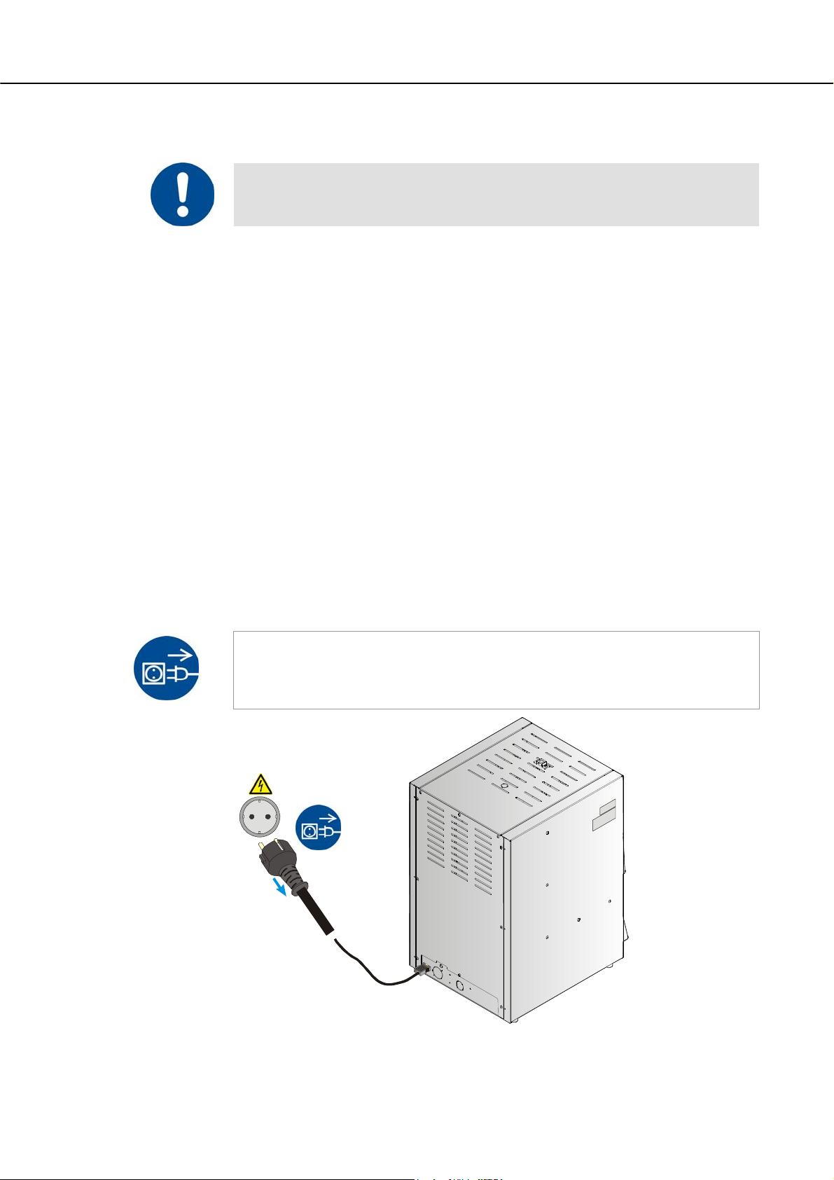
Pos: 59 /TD/Allgemeine Hinweise (für alle Anleitungen) /Hinweis - Das Stillsetzen im Notfall ist vorgeseh en dur ch Ziehen des Netzsteckers. @ 6\mod_1222062836860 _51. doc @ 42829 @ @ 1
Note
The power plug is to be pulled out to stop the oven in case of an emergency. Therefore,
the power plug must be accessible at all times when the oven is operating so that it can be
Pos: 60 /TD/Sicherheit/Grundlegende Maßnahmen im Notf a ll - Netzstecker ziehen LHT/HTC-Renishaw - Grafi k @ 10\ mod_1253804741998_51.doc @ 66279 @ @ 1
pulled out quickly in case of an emergency.
20
Fig. 4: Pulling the power plug
Page 21

Pos: 61 /TD/Allgemeine Hinweise (für alle Anleitungen) /Warnung - Bei unerwarteten Vorgängen im Ofen (z.B. star ke Rauchentwicklung oder Geruchsbelästigung) @ 4\mod_ 1205 306579737_51.doc @ 34218 @ @ 1
Risks during Normal Operation!
Switch the oven off immediately in case of unexpected occurrences in the oven (e.g. a lot of
smoke or unusual smells). Wait until the oven has cooled naturally to room temperature.
Pos: 62 /TD/Sicherheit/Sicherheitssymbole/W arnhinweise-ISO-ANSI/Warnsymbol_Gefahr - Elektrischer Schlag - Piktogramm elektr. Schlag - Hauptsc halter @ 9\mod_1247472185096_51.doc @ 63063 @ @ 1
DANGER
• Danger of electric shock.
• Risk of fatal injury.
• Work on electrical
equipment may be carried out only by
qualified electricians
or by trained personnel authorized by
Nabertherm.
• Before starting work, pull out the
power plug
Pos: 63 /TD/Sicherheit/Überschrift - Grundlegende Maßnahmen bei Wartung und Instandhaltung @ 0\mod_11678260 60620_51.doc @ 5193 @ 2 @ 1
3.7 Basic Measures for Servicing and Maintenance
Pos: 64 /TD/Sicherheit/Grundlegende Maßnahmen bei W artung und Instandhaltung @ 0\mod_1158222458436_51.doc @ 2188 @ @ 1
Maintenance work must be performed by authorized persons following the maintenance
instructions and the accident prevention regulations. We recommend that the maintenance
and repair work be carried out by the service team of Nabertherm GmbH. Non-compliance
may cause injuries, death, or considerable damage to property.
Switch off the oven and make sure it cannot be switched on again inadvertently (lock the
main switch and secure it with a padlock), or pull out the power plug.
Clear an adequate area around the oven to facilitate the repair work.
Suspended loads are dangerous. Working beneath a suspended load is prohibited. There is a
risk of fatal injury.
Relieve the pressure on hydraulic equipment before carrying out maintenance or repair
work (if applicable).
When cleaning ovens, control cabinets, or electrical equipment housings, never spray them
with water.
When maintenance or repair work has been completed, before recommencing production
ensure the following:
Check that loosened screw connections have been re-tightened,
Reinstall protective equipment, screens, and filters,
Remove all material, tools, and other equipment used for the maintenance or repair
work from the working area of the oven,
Remove any liquids that have leaked,
Check that all safety functions (e.g. emergency stop button) work properly,
Power cables may be replaced only with similar, approved cables.
Pos: 65 /=== Seitenumbruch === @ 0\mod_1158819844943_0.doc @ 2983 @ @ 1
21
Page 22

Pos: 66 /TD/Sicherheit/Überschrift - Umweltschutz vorschriften @ 0\mod_1167826189237_51.doc @ 5202 @ 2 @ 1
3.8 Environmental Regulations
Pos: 67 /TD/Sicherheit/Umweltschutzvorschr iften Schmierfette-Hydrauliköl-Kühlmittel @ 0\ mod_1158223424304_51.doc @ 2199 @ @ 1
All statutory duties regarding waste avoidance, proper recycling, and disposal must be
observed when work is carried out on and with the oven.
Problem materials that are no longer needed, such as lubricants or batteries, must not be
placed in normal waste disposal systems or allowed to enter the sewage system.
During installation, repair, and maintenance work, substances that are hazardous to water,
such as
lubricating grease and oils
hydraulic oils
refrigerants
solvent-based cleaning fluids must not be allowed to contaminate the soil or enter
the sewage system.
These substances must be stored, transported, collected, and disposed of in suitable
containers.
Note
The operator must ensure that national environmental regulations are observed.
Pos: 68 /TD/Sicherheit/Umweltschutzvorschr iften Elektronische Bauteile-Isolierung-Al tmetall @ 4\mod_1205143314853_51.doc @ 32563 @ @ 1
Pos: 69 /=== Seitenumbruch === @ 0\mod_1158819844943_0.doc @ 2983 @ @ 1
When it is delivered, this oven contains no substances that make a hazardous waste
classification necessary. However, residues of process materials may accumulate in the
oven insulation during operation. These may be hazardous to health and/or the
environment.
Dismantle the electronic components and dispose of them as electric scrap.
Remove the insulation and dispose of it as hazardous waste (See Servicing,
Cleaning, and Maintenance with Ceramic Fiber Material)
Dispose of the housing as scrap metal.
22
Page 23

Pos: 70 /TD/Sicherheit/Sicherheitssymbole/W arnhinweise-ISO-ANSI/Erläuterung ANSI Z535.6 @ 8\ mod_1243323558881_51.doc @ 57444 @ 2 @ 1
3.9 Explanation of the Symbols and Warnings
Note
NOTICE
In the following operating instructions, specific warnings are given to draw attention to
residual risks that cannot be avoided when the oven is operating. These residual risks
include dangers for humans/products/ the oven, and the environment.
The symbols used in the operating instructions are especially intended to draw attention to
safety information.
The symbols used cannot replace the text of the safety information. Therefore, always read
the entire text.
Graphic symbols correspond to ISO 3864. In accordance with the American National
Standard Institute (ANSI) Z535.6 the following warning information and words are used in
this document:
The general hazard symbol, in combination with the words CAUTION, WARNING and
DANGER warns about the risk of serious injury. Observe the following information to
prevent injury or death.
Refers to a hazard that could damage or destroy the equipment.
CAUTION
WARNING
DANGER
Refers to a hazard with a minor or medium risk of injury.
Refers to a hazard that could cause death, serious or irreversible injury.
Refers to a hazard that could directly cause death, serious or irreversible injury.
Structure of the warning: All warnings are structured as follows
Hazard symbol
Indicates the risk of injury
Signal word
Classifies the danger
WARNING
• Type and source of the danger
• Consequences of non-compliance
• Action to prevent danger
Graphical symbols (optional)
according to ISO 3864:
Consequences, measures, and
prohibitions
Reference texts:
• Type and source of the danger
• Possible consequences of noncompliance
• Measures/Prohibitions
23
Page 24

Pos: 71 /TD/Sicherheit/Sicherheitssymbole/W arnhinweise-ISO-ANSI/Überschrift - Hinweissy mbole in der Anleitung @ 9\mod_1247053429626_51.doc @ 62751 @ @ 1
Pos: 72 /TD/Sicherheit/Sicherheitssymbole/W arnhinweise-ISO-ANSI/Hinweis - Unter diesem Sy mbo l er halten Sie Anweisungshinweise und ... @ 9\mod_1247053932 311_51.doc @ 62785 @ @ 1
or
Hazard symbol
Indicates the risk of injury
Signal word
Classifies the danger
DANGER
• Type and source of the danger
• Consequences of non-compliance
• Action to prevent danger
Graphical symbols (optional)
according to ISO 3864:
Consequences, measures, and
prohibitions
Graphical symbols
(optional) according to ISO
3864:
Instructions or prohibitions
Reference texts:
• Type and source of the danger
• Possible consequences of noncompliance
• Measures/prohibitions
Information Symbols in the Instructions:
Note
Below this symbol you will find instructions and particularly useful information.
Pos: 73 /TD/Sicherheit/Sicherheitssymbole/W arnhinweise-ISO-ANSI/Piktogramm in der Anleitu ng - Gebot - Gebotszeichen - Wichtige Gebote sind zu befolgen @ 9\ mo d_12 47056175982_51.doc @ 62853 @ @ 1
Pos: 74 /TD/Sicherheit/Sicherheitssymbole/W arnhinweise-ISO-ANSI/Piktogramm in der Anleitu ng - Gebot - Wichtige Information für den Bediener @ 9\mod_1247053 200729_51.doc @ 62717 @ @ 1
Pos: 75 /TD/Sicherheit/Sicherheitssymbole/W arnhinweise-ISO-ANSI/Piktogramm in der Anleitu ng - Gebot - Wichtige Information für das Wartungspersona l @ 9\mod_1247053206042_51.doc @ 62734 @ @ 1
Pos: 76 /TD/Sicherheit/Sicherheitssymbole/W arnhinweise-ISO-ANSI/Piktogramm in der Anleitu ng - Gebot - Netzstecker ziehen @ 9\mod_1247055471526_51.doc @ 62836 @ @ 1
Pos: 77 /TD/Sicherheit/Sicherheitssymbole/W arnhinweise-ISO-ANSI/Piktogramm in der Anleitu ng - Gebot - Anheben mit mehreren Personen @ 9\mod_1247063058002_5 1.doc @ 62938 @ @ 1
Rule - Rule Sign
This symbol draws attention to important rules that must be followed. Rule signs protect
people against injury and show what is to be done in certain situations.
Rule - Important Information for Operators
This symbol draws the operator's attention to important information and operating
instructions that must be followed.
Rule - Important Information for Maintenance Personnel
This symbol draws the maintenance personnel's attention to important operating and
maintenance instructions (service) that must be followed.
Rule - Pull Out the Power Plug
This symbol tells the operator to pull out the power plug.
24
Page 25

Pos: 78 /TD/Sicherheit/Sicherheitssymbole/W arnhinweise-ISO-ANSI/Piktogramm in der Anleitu ng - Warnung - Heiße Oberfläche - Oberfläche nicht berühren @ 9\ mod_1247054774780_51.doc @ 62802 @ @ 1
Pos: 79 /TD/Sicherheit/Sicherheitssymbole/W arnhinweise-ISO-ANSI/Piktogramm in der Anleitu ng - Warnung - elektrischer Schlag - zur Vermeidung Anweisung f olgen @ 9\mod_1247055093892_51.doc @ 62819 @ @ 1
Pos: 80 /TD/Sicherheit/Sicherheitssymbole/W arnhinweise-ISO-ANSI/Piktogramm in der Anleitu ng - Warnung - Umkippen des Gerätes @ 9\mod_1247059198372_5 1. doc @ 62870 @ @ 1
Pos: 81 /TD/Sicherheit/Sicherheitssymbole/W arnhinweise-ISO-ANSI/Piktogramm in der Anleitu ng - Warnung - Schwebende Lasten @ 9\mod_1251450500309_51.doc @ 65454 @ @ 1
Pos: 82 /TD/Sicherheit/Sicherheitssymbole/W arnhinweise-ISO-ANSI/Piktogramm in der Anleitu ng - Warnung - Heben schwerer Lasten @ 9\mod_1247059891358_51.doc @ 62887 @ @ 1
Pos: 83 /TD/Sicherheit/Sicherheitssymbole/W arnhinweise-ISO-ANSI/Piktogramm in der Anleitu ng - Warnung - Umweltgefährdung @ 9\mod_1247060443419_51.doc @ 62904 @ @ 1
Pos: 84 /TD/Sicherheit/Sicherheitssymbole/W arnhinweise-ISO-ANSI/Piktogramm in der Anleitu ng - Warnung - Brandgefahr @ 9\mod_1251445272822_51.doc @ 65437 @ @ 1
Pos: 85 /TD/Sicherheit/Sicherheitssymbole/W arnhinweise-ISO-ANSI/Piktogramm in der Anleitu ng - Warnung - Explosionsgefährliche Stoffe @ 9\mod_124706114 8859_51.doc @ 62921 @ @ 1
Rule - Lift only with Several People
This symbol draws the personnel's attention to the fact that this device may only be lifted
and moved to its final destination by several people.
Warning - Hot Surface, Do Not Touch
This symbol warns the operator that the surface is hot and should not be touched.
Warning - Danger of Electric Shock
This symbol warns the operator that there is a risk of an electric shock if the following
warnings are not heeded.
Warning – Risk of Device Toppling Over
This symbol tells the operator that there is a risk of the device toppling over if the following
warnings are not heeded.
Warning – Suspended Load
This symbol warns the operator of potential dangers of suspended loads. Working below a
suspended load is strictly forbidden. Ignoring this can lead to fatal injury.
Warning – Danger if Heavy Loads Are Lifted
This symbol warns the operator of the potential dangers of lifting heavy loads. Ignoring this
can lead to injury.
Warning – Risk to the Environment
This symbol warns the operator of the risk to the environment if the following information
is not heeded. The operator must ensure that national environmental regulations are
observed.
Warning - Fire Danger
This symbol warns operators of the danger of fire if the following information is not
followed.
Warning – Risk of Explosive Substances or
Explosive Atmosphere
These symbols warn the operator of explosive substances or an explosive atmosphere
Pos: 86 /TD/Sicherheit/Sicherheitssymbole/W arnhinweise-ISO-ANSI/Piktogramm in der Anleitu ng - Gefahr - nicht mit Wasser überschütten @ 9\mod_1247826410 886_51.doc @ 63819 @ @ 1
Pos: 87 /TD/Sicherheit/Sicherheitssymbole/W arnhinweise-ISO-ANSI/Überschrift - Warnhi nweis symbole an der Anlage @ 9\mod_1247053700273_51.doc @ 62768 @ @ 1
Pos: 88 /TD/Sicherheit/Sicherheitssymbole/W arnhinweise-ISO-ANSI/Piktogramm an der Anlage - W ar nung - Gefahr vor heißer Oberfläche und Verbrennung @ 9\mod_1247 0529 57145_51.doc @ 62700 @ @ 1
Pos: 89 /TD/Sicherheit/Sicherheitssymbole/W arnhinweise-ISO-ANSI/Piktogramm an der Anlage - W arnung - Gefahren durch elektrischen Strom @ 9\mod_124705263982 4_51.doc @ 62683 @ @ 1
Pos: 90 /=== Seitenumbruch === @ 0\mod_1158819844943_0.doc @ 2983 @ @ 1
Prohibited - Important Information for Operators
This symbol warns the operator that water or cleaning products must NOT be poured over
the objects. A high-pressure cleaning device must also not be used.
Warning Signs on the Oven:
Warning - Hot Surface, Danger of Burning – Do Not Touch
You may not always realize that surfaces, such as oven components, oven walls, doors and
materials, and even liquids are hot. Do not touch the surface.
Warning - Danger of Electric Shock!
Warning, dangerous electric voltage
25
Page 26

Pos: 91 /TD/Sicherheit/Überschrift - Allgemeine Gefahren an der Anlage @ 0\mod_1168596796288_51.doc @ 6014 @ 2 @ 1
3.10 General Risks with the Oven
Pos: 92 /TD/Sicherheit/Allgemeine Gefahren (Ver br ennung, Quetschen, Strom) - Laboröfen @ 2\mod_118466602302 2_51.doc @ 19974 @ @ 1
Warning! General hazards!
- Risk of burning on the furnace housing and on the tube
- The door handle/grip can become very hot during operation; wear gloves.
- Risk of crushing on moving parts (door hinge, rotary tube drive,
lifting table, etc.)
- The switchgear cabinet (if present) and the terminal boxes on the system contain
dangerous electrical voltages.
- Do not insert any objects into the openings on the furnace housing, exhaust air holes, or
cooling slots on the
switchgear or furnace (if present). This poses a risk of electric shock.
Pos: 93 /TD/Allgemeine Hinweise (für alle Anleitungen) /Warnung - Es dürfen keine Gegenstände auf den/der Ofen/Sc haltanlage abgelegt/abgestellt werden... @ 4\mod_1203924555465_51.doc @ 31568 @ @ 1
Pos: 94 /=== Seitenumbruch === @ 0\mod_1158819844943_0.doc @ 2983 @ @ 1
Warning! General hazards!
No objects may be placed or set down on the furnace or switchgear. Doing so creates a fire
or explosion hazard.
26
Page 27
Pos: 95 /TD/Transport_Montage_Inbetriebnahme/E r stinbetriebnahme/Überschrift - Transport, Montage und Erstinbetriebnahme @ 0\mod_1158844227416_51. doc @ 3112 @ 1 @ 1
4 Transportation, Installation, and Commissioning
Pos: 96 /TD/Transport_Montage_Inbetriebnahme/Er stinbetriebnahme/Überschrift - Anliefer ung @ 0\mod_1167826534889_51.doc @ 5220 @ 2 @ 1
4.1 Delivery
Pos: 97 /TD/Transport_Montage_Inbetriebnahme/Er stinbetriebnahme/Anlieferung - (Hinweise a l lgemein) @ 0\mod_1158233508887_51.doc @ 2223 @ @ 1
Check that Everything is Complete
Compare the delivered items with the delivery note and the purchase order documents.
Immediately notify the carrier and Nabertherm GmbH of any missing or damaged parts, as
complaints at a later date cannot be acknowledged.
Danger of Injury
When the oven is being lifted, parts of the oven or the oven itself could topple over, slip, or
fall. Before the oven is lifted, make sure no one is in the working area. Wear safety
footwear and a hard hat.
Safety Instructions
Forklifts must be operated only by authorized personnel. The operator bears sole
responsibility for safe operation and the load.
When the oven is being lifted, make sure that the ends of the forks or the load do
not catch on neighboring goods. Use a crane to move tall parts, such as control
cabinets.
Use only lifting equipment with sufficient load-bearing capacity.
Lifting gear must be attached only to positions that have been designated for this
purpose.
Attachments, piping, or cable conduits must never be used to affix lifting gear.
Unpackaged parts should only be lifted with ropes or straps.
Attach transportation equipment only to positions intended for this purpose.
Lifting and securing equipment must conform to the provisions contained in
accident prevention regulations.
Consider the weight of the oven when choosing lifting and securing equipment.
(see Specifications)
Stainless steel parts (including mounting elements) must always be kept separate
from unalloyed steel parts.
Do not remove corrosion protection until immediately prior to assembly.
Risks during Normal Operation!
Suspended loads are dangerous. Working beneath a suspended load is prohibited. There is a
risk of fatal injury.
Pos: 98 /=== Seitenumbruch === @ 0\mod_1158819844943_0.doc @ 2983 @ @ 1
Note
Safety and accident prevention guidelines applicable for forklift trucks must be followed.
27
Page 28
Pos: 99 /TD/Transport_Montage_Inbetriebnahme/Er stinbetriebnahme/Anlieferung von Öfen mit eine m Hub wagen @ 2\mod_1184672460200_51.doc @ 20000 @ @ 1
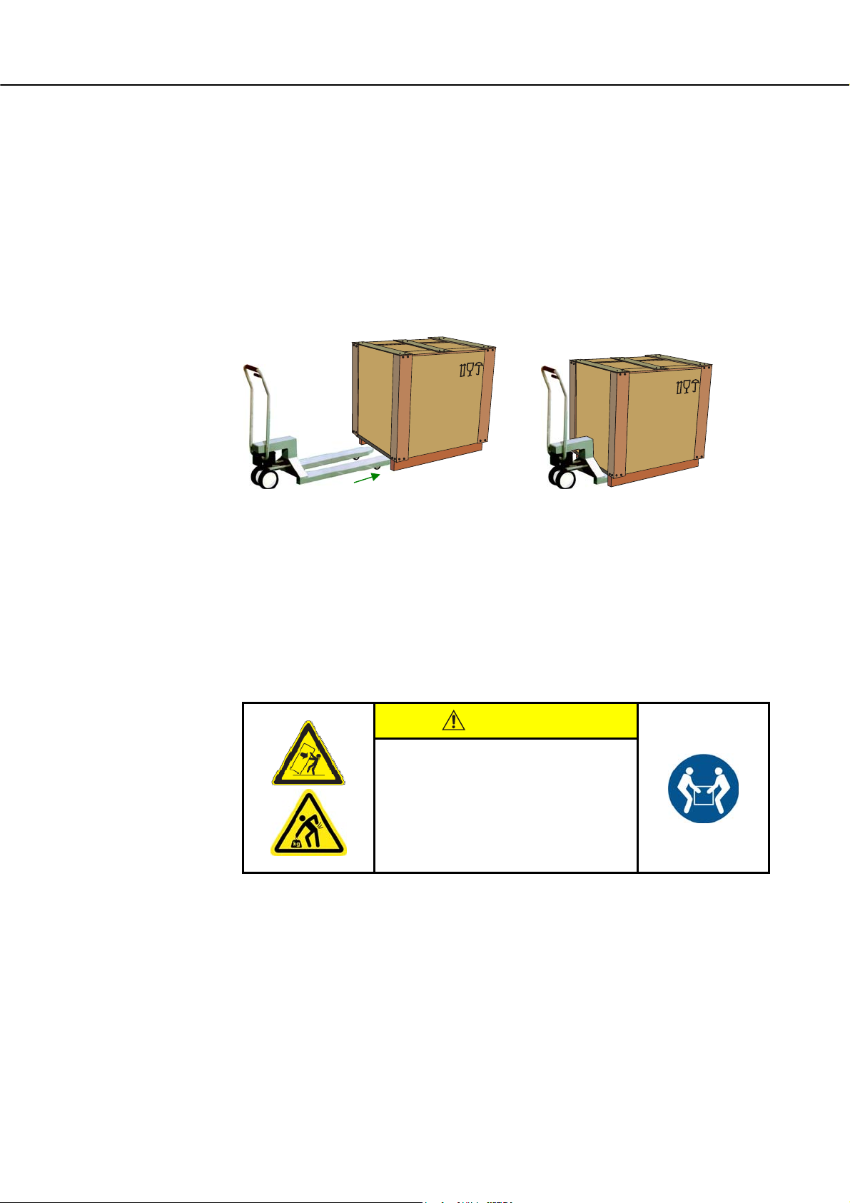
Transportation with a Pallet Truck
Observe the maximum permitted capacity of the pallet truck.
1. Our ovens are delivered ex works on wooden frames to facilitate unloading.
Transport the oven in its original packaging and with suitable equipment to prevent
any damage. Remove the packaging only when the oven is in its final location.
When transporting the oven, make sure it is secured against sliding, toppling over,
and damage. The oven should be transported and installed by at least two persons.
Do not store the oven in damp rooms or outdoors.
2. Push the pallet truck underneath the transportation frame. Make sure that the pallet
truck is completely beneath the frame. Pay attention to neighboring goods.
Pos: 100 /TD/Sicherheit/Sicherheitssymbole/ W arnhinweise-ISO-ANSI/Warnsymbol_Vorsic ht - Rutschen/Kippen des Gerätes - Piktogramm Kippen/He ben/ Anheben @ 9\mod_1247064081950_51.doc @ 62955 @ @ 1
Pos: 101 /=== Seitenumbruch === @ 0\mod_1158819844943_0. doc @ 2983 @ @ 1
Fig. 5: Pallet truck is pushed completely beneath the transportation frame
3. Lift the oven carefully and pay attention to its center of gravity. When the oven is
being lifted, make sure that the ends of the forks or the load do not catch on
neighboring goods.
4. Make sure that the oven is balanced safely; if not, attach securing equipment. Push
the oven carefully, slowly and with the pallet truck at its lowest position. Do not
transport the oven on inclines.
5. Carefully lower the oven at its final position. Pay attention to neighboring goods.
Try not to set it down too abruptly.
CAUTION
• Device may slip or topple over.
• Damage to the device.
• Risk of injury from lifting
heavy loads.
• Transport device only in original
packaging.
• Several people must carry the device.
28
Page 29
Pos: 102 /TD/Transport_Montage_Inbetriebnahme/E r stinbetriebnahme/Legende für Packstücke z.B. zerbrechlich @ 1\mod_1173776713307_51.doc @ 10746 @ @ 1
Symbols:
The international standard symbols for handling packaging are defined in ISO R/780
(International Organization for Standardization) and in DIN 55 402 (German Institute for
Standardization).
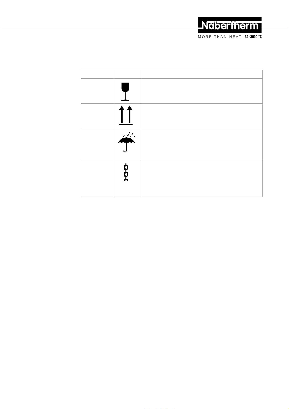
Description Symbol Explanation
Pos: 103 /=== Seitenumbruch === @ 0\mod_1158819844943_0. doc @ 2983 @ @ 1
Fragile
This side up
Keep dry
Sling here
This symbol is to be attached to fragile goods. Goods
marked like this are to be handled carefully and must not be
thrown or tied up.
The freight must be transported, transshipped, and stored in
such a way that the arrows point upward. The freight must
not be rolled, folded, or stored on edge. However, the
package does not have to be packed on top of other freight.
Products with this symbol must be protected against high air
moisture, hence, they must be stored under cover. If
particularly heavy or bulky packages cannot be stored in
halls or sheds, they must be covered carefully with a
tarpaulin or similar.
The symbol shows only where the sling should be attached,
not the method of slinging. If the symbols are at an equal
distance from the middle or center of gravity of the package,
the package hangs straight if the slings are the same length.
If this is not the case, the sling on one side has to be
shortened.
29
Page 30

Pos: 104 /TD/Transport_Montage_Inbetriebnahme/Er stinbetriebnahme/Überschrift - Auspac ken @ 2\mod_1184739517985_51.doc @ 20013 @ 2 @ 1
4.2 Unpacking
Pos: 105 /TD/Allgemeine Hinweise (für alle Anleitungen) /Hinweis - Allgemeiner Hinweis zur Verpackung (z. B. Laboröfen) @ 3\mod_1192437185846_51.doc @ 23509 @ @ 1
Pos: 106 /TD/Transport_Montage_Inbetriebnahme/E r stinbetriebnahme/Auspacken Laborofen - LHT- Tisc hmodell , R, RT - Teil 1 @ 2\mod_1184739616497_51.doc @ 20026 @ @ 1
Wear protective
gloves
Note
The oven packaging prevents damage during transportation. Make sure that you remove all
packaging material (also inside the oven chamber). Keep the packaging and transportation
securing equipment in case it is needed for future transportation or storage.
At least two people are needed to carry/transport the oven, more for larger ovens.
Pos: 107 /TD/Transport_Montage_Inbetriebnahme/Er stinbetriebnahme/Auspacken Hochtemperatur ofen - HTCT 01/14-16-Tischmodell - Teil 2 @ 12\mod_1281942490 665_51.doc @ 96845 @ @ 1
Pos: 108 /TD/Transport_Montage_Inbetriebnahme/Er stinbetriebnahme/Auspacken-Tragen Labor ofen - LHT-Tischmodell - Teil 3 @ 3\mod_1192436920381_5 1. doc @ 23483 @ @ 1
1
2
1. Check the transportation packaging for possible damage.
2. Remove tensioning straps from the transportation packaging.
3. Slacken screws and remove wooden casing from the covering box (if available).
4
5
6
4. Carefully lift the cardboard box and remove it from the pallet.
5. Remove the foam insert in the box. The box contains a packaging unit for
accessories (Example: exhaust air tube, insert plate, power cable). Compare the
delivered items with the delivery note and the order documents, see "Delivery".
6. Carefully lift the furnace out of the packaging unit.
3
30
Page 31
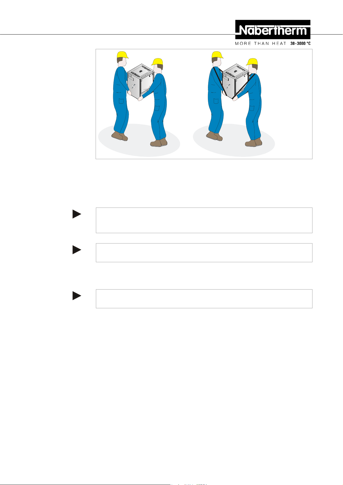
7. To carry, grip furnace from below at the sides and make sure you have a firm grip.
8. For furnaces weighing more than 25 kg, transport work must be carried out by at
least 2 people. If transport straps are used, they must be attached crosswise only.
Ensure that they are secure.
Note
In Germany, the general accident protection guidelines of VBG or BGZ must be observed.
The national accident prevention regulations of the country of operation apply.
Note
Save the packaging for possible shipping or for storing the furnace.
Pos: 110 /TD/Transport_Montage_Inbetriebnahme/Er stinbetriebnahme/Überschrift - Transpor tsi c herung/Verpackung @ 0\mod_1167826775847_51.doc @ 5229 @ 2 @ 1
4.3 Transportation Securing Equipment/Packaging
Pos: 111 /TD/Transport_Montage_Inbetriebnahme/E r stinbetriebnahme/Verpackung - Allgemeine Hin weise zur Verpackung - keine spezielle Transportsi c herung @ 1\mod_1171004073117_51.doc @ 9153 @ @ 1
Note
No special transportation securing equipment is available for this oven
The oven packaging prevents damage during transportation. Make sure that you remove all
packaging material (also inside the oven chamber). All packaging material can be recycled.
The packaging was designed so that no special description is necessary.
Pos: 112 /=== Seitenumbruch === @ 0\mod_1158819844943_0. doc @ 2983 @ @ 1
31
Page 32

Pos: 113 /TD/Transport_Montage_Inbetriebnahme/E r stinbetriebnahme/Überschrift - Baulic he- und Anschlussvoraussetzungen @ 0\mod_1167826890943_ 51.doc @ 5238 @ 2 @ 1
4.4 Constructional and Connection Requirements
Pos: 114 /TD/Transport_Montage_Inbetriebnahme/E r stinbetriebnahme/Überschrift - Auf stellung ( Standort des Ofens) @ 2\mod_1184848718972_51.doc @ 20166 @ 3 @ 1
4.4.1 Installation (Oven Location)
Pos: 115 /TD/Transport_Montage_Inbetriebnahme/Er stinbetriebnahme/Standort eines LHT-Ofens @ 2\ mod_1184852454302_51.doc @ 20179 @ @ 1
When setting up the furnace, the following safety instructions must be followed:
The furnace must be installed in a dry room in accordance with the safety
instructions.
The table/supporting surface must be flat to enable the furnace to be installed
straight. The furnace must be placed on a noncombustible base (stone, metal,
etc.).
The carrying capacity of the table must be designed to bear the weight of the
furnace incl. accessories.
The floor covering must be made of nonflammable material so that hot material
falling out of the furnace will not cause the floor covering to ignite.
Despite good insulation, the furnace radiates heat from its external surfaces. If necessary,
this heat must be conducted away (a ventilation engineer must be consulted if required).
In addition, the furnace must be positioned a minimum safety distance (S) of 0.5 m on each
side and 1 m at the top away from combustible materials. In individual cases, more space
must be chosen in order to match the local conditions. The minimum distance away from
noncombustible materials may be reduced to 0.2 m at the sides.
Should gases or vapors escape from the charge, then sufficient air supply and ventilation at
the installation location or an appropriate exhaust gas line must be provided.
A suitable exhaust for the burner exhaust must be provided by the customer.
Pos: 116 /TD/Sicherheit/Sicherheitssymbole/W arnhinweise-ISO-ANSI/Warnsymbol_Gefahr - Brandgefahr - Piktogramm Brandgefahr @ 9\mod_1247148035738_ 51.doc @ 63010 @ @ 1
Pos: 117 /TD/Allgemeine Hinweise (für alle Anleitungen) /Hinweis - Vor Inbetriebnahme des Ofens sollte die ser 24 Stunden am Aufstellungsort akklimatisiert .. @ 3\mod_1195568014336_51.doc @ 27871 @ @ 1
S
S
S
S
Noncombustible base
Fig. 6: Installation (Oven Location)
DANGER
• Fire- danger to health.
• Risk of fatal injury.
• Adequate ventilation must be ensured at the
installation location to conduct waste heat and any
exhaust gases away.
Note
Before starting the oven for the first time, allow it to acclimatize at its installation location
for 24 hours.
32
Page 33

Pos: 119 /TD/Transport_Montage_Inbetriebnahme/E r stinbetriebnahme/Überschrift - Montage, Ins tallation und Anschluss @ 0\mod_1167827976269_51. doc @ 5292 @ 2 @ 1
4.5 Assembly, Installation, and Connection
Pos: 120 /TD/Transport_Montage_Inbetriebnahme/E r stinbetriebnahme/Überschrift - Montage eines A bz ugskamins @ 14\mod_1300115306448_51.doc @ 113409 @ 2 @ 1
4.6 Assembly of a Vent
Pos: 121 /TD/Transport_Montage_Inbetriebnahme/E r stinbetriebnahme/Abzugskamin Laboröfen - all gemeiner Text @ 14\mod_1300115642723_51.doc @ 113432 @ @ 1
Which vents are supplied vary depending on the application/order (doe s not apply
to protective gas connection):
Pos: 122 /TD/Transport_Montage_Inbetriebnahme/ Er stinbetriebnahme/Abzugskamin Laboröfen - A bzugs kamin zum Anschluss an ein Abluftrohr @ 14\mod_13001161 4377 6_51.doc @ 113455 @ @ 1
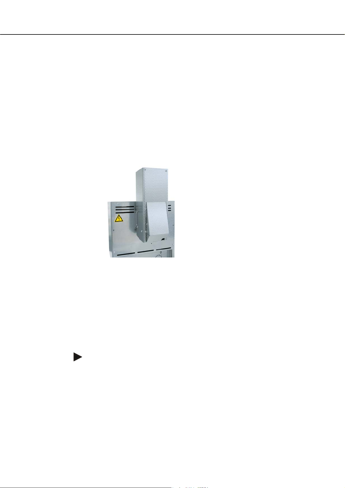
Vent (not for LV models)
Vent which exhausts the escaping gases and vapors through the exhaust air
connecting piece (back wall) and releases them overhead. Exhaust air cross
section: 40 x 30 mm
Install by slipping the vent onto the connecting piece on the back wall of the
furnace and fasten it with the screws included in the scope of delivery.
Pos: 123 /TD/Transport_Montage_Inbetriebnahme/E r stinbetriebnahme/Abzugskamin Laboröfen - Abzugs kamin mit Ventilator @ 14\mod_1300116418296_51.doc @ 113478 @ @ 1
Pos: 124 /TD/Transport_Montage_Inbetriebnahme/E r stinbetriebnahme/Abzugskamin Laboröfen - K ata lysator @ 14\mod_1300116553629_51.doc @ 113501 @ @ 1
Fig. 7: Vent
Vent with fan (not for LV models)
Supports the venting of gases and vapors from the furnace chamber. Exhaust air
cross section: 85 x 60 mm
Install by slipping the vent onto the connecting piece on the back wall of the
furnace and fasten it with the screws included in the scope of delivery. Plug the
connecting plug into the socket on the back of the switchgear (optional) or in an
external socket.
Fig. 8: Vent with fan
Vent with fan and catalytic converter (not for LV models)
Heats the gases and vapors from the furnace chamber to approx. 600 °C and feeds
it through the catalytic converter honeycomb. The converter incinerates most of
33
Page 34
the organic substances, i.e. breaks them down into carbon dioxide and steam. This
largely eliminates any annoying odors (for example, during dewaxing).
Warning! Inorganic substances such as heavy metals halogens, silicons and
particulates (even in small quantities) will destroy the catalytic converter!
The temperature of the catalytic converter must be checked; from the start of the
program the converter must be operating at approx. 600 °C. A statement cannot be
made regarding residues which may be released into the environment. This is
largely dependent on the individual materials/embedding masses used and their
compositions. Exhaust air cross section: 120 x 120 mm
Installation: Fasten the U-shaped brackets to the back wall of the furnace using the
screws included in the scope of delivery, slide the included section of pipe onto the
connecting piece of the furnace and screw the vent (with CAT) firmly to the
bracket. Plug the power plug into the socket on the back side (optional) of the
switchgear or into an external socket.
Pos: 125 /TD/Transport_Montage_Inbetriebnahme/E r stinbetriebnahme/Abzugskamin Laboröfen - Mon tag e eines Abgasrohres bei LV-Ofenmodelle @ 14\mod_1300118 616710_51.doc @ 113547 @ @ 1
Pos: 126 /=== Seitenumbruch === @ 0\mod_1158819844943_0. doc @ 2983 @ @ 1
Fig. 9: Catalytic converter
Installation of a Exhaust Gas Pipe on LV(T) …/… Models
These models come with a special exhaust gas pipe.
Begin the installation by fastening the rectangular pipe to the inner housing of the
furnace with the screws included in the scope of delivery, then by fastening the
rounds section to the outer housing. The screws included in the scope of delivery
are for this purpose.
Operating the furnace without this pipe results in a reduced air flow which is
insufficient for an incinerating process.
Caution
The installation of a catalytic converter or vent with fan is not possible on these
models.
34
Page 35
A
A
Pos: 127 /TD/Transport_Montage_Inbetriebnahme/Er stinbetriebnahme/Überschrift - Abgasf ührung @ 0\mod_1167828513042_51.doc @ 5310 @ 3 @ 1
4.6.1 Waste Gas System
Pos: 128 /TD/Transport_Montage_Inbetriebnahme/Er stinbetriebnahme/Abgasführung Laborofen L- LE-L(T)-LV(T)-SKM-SW-HA @ 14\mod_1300178990365_5 1. doc @ 113593 @ @ 1
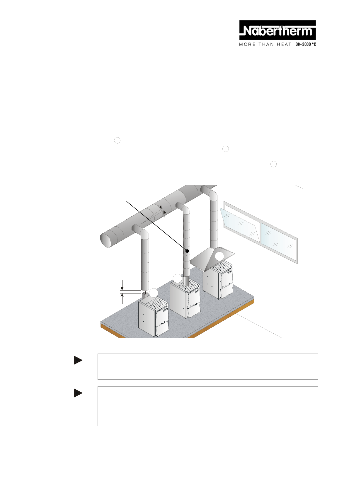
We recommend connecting an exhaust air pipe to the furnace to remove the
exhaust gases.
For this purpose you can use a commercially available, metal exhaust gas pipe
with NW80 to NW120. It must be installed continuously rising and fastened to the
wall or ceiling. Center the pipe over the furnace vent (for models with vent fan or
catalytic converter, NW 120 is necessary.
The exhaust gas pipe must not be installed with a tight fit to the furnace vent pipe
since this would prevent any bypass effect. This is necessary so that not too much
fresh air is sucked in by the furnace. (An exception are the LV furnaces: Here the
exhaust gas pipe NW80 can be slid directly onto the furnace vent pipe.)
Vent
Exhaust air (model LV/LVT) or vent with fan
directly onto the exhaust air pipe or vent.
Furnaces without exhaust air pipe or with catalytic converter
recommend feeding the exhaust air through a flue.
: Position the exhaust air piping approx. 50 mm over the vent.
B
: Exhaust air piping can be slid
C
: We
Exhaust air piping
C
B
50 mm
Fig. 10: Example: Various ways of removing the exhaust air
Caution
The exhaust gases can only be vented if the workspace is ventilated with an
adequate fresh-air opening.
Caution
The customer is responsible for providing the masonry and roofing work necessary
for venting the exhaust. The size and design of the exhaust air system must be
decided by a ventilation expert. The accident prevention regulations applicable in
the country where the furnace is installed must be followed.
Pos: 129 /=== Seitenumbruch === @ 0\mod_1158819844943_0. doc @ 2983 @ @ 1
35
Page 36

Pos: 130 /TD/Transport_Montage_Inbetriebnahme/E r stinbetriebnahme/Überschrift - 1.1.1 Ansc hluss an das Elektronetz @ 0\mod_1168599727688_51.doc @ 6050 @ 3 @ 1
4.6.2 Connecting the Oven to the Power Supply
Pos: 131 /TD/Transport_Montage_Inbetriebnahme/E r stinbetriebnahme/Anschluss an das Elektronet z - Laborofen-1phasig mit Snap-In-Buchse @ 10\mod_12 538 71914414_51.doc @ 66303 @ @ 1
On the building side, the required services must be provided, i.e. the carrying capacity of
the installation surface, provision of power (electricity), etc.
The furnace must be installed in accordance with its intended use. The power
connection values must correspond to the values on the furnace type plate.
The power socket must be located close to the furnace and must be easily
accessible. The safety requirements are not met if the furnace is not connected to a
socket with grounding contact.
On use of an extension cable or a multipoint socket, the maximum electrical rating
must not be exceeded. Do not use the furnace with an extension cable if you are
uncertain whether grounding is guaranteed.
The power cable must not be damaged. Do not place any objects on the power
cable. Route the cable so that nobody can tread on or stumble over it.
A damaged power cable must be replaced immediately.
Ensure that the furnace's connection cable is routed so that it is protected.
Note
Before connecting the voltage supply, make sure that the power switch is in the "Off" or
"0" position.
Type plate
2.
1.
klick
Fig. 11: Illustrated power cable enclosed in the scope of delivery
1. First connect the enclosed power cable to the intended mains power connector on the
furnace.
2. Now connect the enclosed power cable to the power connection. Only use a socket
with grounding contact to supply power.
36
Page 37

k
Pos: 132 /TD/Transport_Montage_Inbetriebnahme/E r stinbetriebnahme/Anschluss an das Elektronet z - Laborofen-3phasig mit Netzzuleitung @ 14\mod_1300 113354020_51.doc @ 113386 @ @ 1
Abb. 12: Reconnect the power cable
1.
2.
1.
Type plate
klic
Fig. 13: Power connection with power line
1. Connect the power cable to the power connection. Only use a socket with grounding
contact to supply power.
Grounding of the furnace and switching system (compliant with VDE 0100, part 410) is a
prerequisite for the current-operated e.l.c.b. system of the heater.
Test the ground resistance (compliant with VDE 0100); see also accident prevention
guidelines.
Electrical systems and equipment compliant with BGV A3.
Note
For wiring and electrical connections, see the attached wiring diagram. The electrical
equipment of the machine can also be seen in the wiring diagram.
Note
The national regulations of the country of operation apply.
37
Page 38

Warning - danger due to electrical current!
Work on the electrical equipment may only be performed by qualified, authorized
electricians.
Pos: 133 /TD/Allgemeine Hinweise (für alle Anleitungen) /Hinweis - Verdrahtung und Elektrische Anschlüsse en tnehmen Sie dem beiliegendem Schaltplan. @ 5\mod_12199238 93347_51.doc @ 41881 @ @ 1
Pos: 134 /TD/Sicherheit/Sicherheitssymbole/W arnhinweise-ISO-ANSI/Warnsymbol_Achtung - falsche Netzspannung - Piktogramm Gebotszeichen @ 9\ mod_1247475231381_51.doc @ 63131 @ @ 1
Pos: 135 /TD/Sicherheit/Sicherheitssymbole/W arnhinweise-ISO-ANSI/Warnsymbol_Gefahr - Brandgefahr - Piktogramm Brandgefahr @ 9\mod_1247148035738_ 51.doc @ 63010 @ @ 1
Note
For wiring and electrical connections, see the attached circuit diagram. The electrical
equipment of the machine can also be seen in the circuit diagram.
NOTICE
• Danger from incorrect voltage
• Damage to the oven.
• Check voltage before connecting and
commissioning the oven.
• Compare the voltage with the details
on the type plate.
DANGER
• Fire- danger to health.
• Risk of fatal injury.
• Adequate ventilation must be ensured at the
installation location to conduct waste heat and any
exhaust gases away.
Pos: 136 /=== Seitenumbruch === @ 0\mod_1158819844943_0. doc @ 2983 @ @ 1
38
Page 39
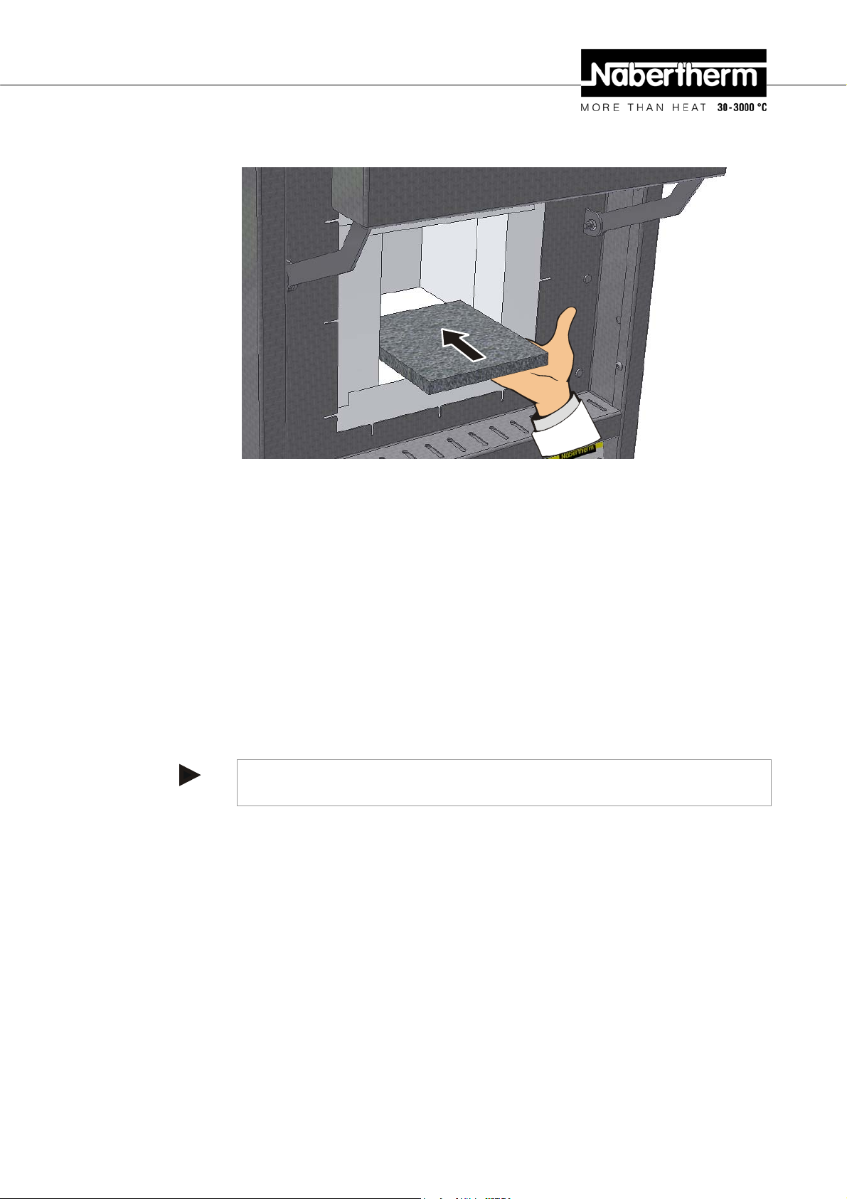
Pos: 137 /TD/Transport_Montage_Inbetriebnahme/Er stinbetriebnahme/Überschrift - Einlegen der Bodenplatte LHT-Ofen @ 2\mod_1185287183100_51.doc @ 20422 @ 3 @ 1
4.6.3 Insertion of the Base Plate
Pos: 138 /TD/Transport_Montage_Inbetriebnahme/Er stinbetriebnahme/Einlegen der Einlegepla t te (Bodenplatte) LHT/HTC/HTCT-Öfen @ 2\mod_1185287451 644_ 51.doc @ 20435 @ @ 1
Fig. 14: Inserting the ceramic insert plate
Swivel the furnace lift-door carefully away upwards. Carefully place the ceramic insert
plate/s (quantity of insert plates dependent on furnace model) centrally on the base of the
furnace. When inserting the ceramic insert plate/s, ensure that the door collar and the
heating elements are not damaged. Under all circumstances, avoid coming into contact with
the heating elements when inserting the insert plate/s; this may lead to the immediate
destruction of the heating elements.
The base of the furnace is manufactured from high-quality, fireproof material which is
extremely sensitive to impact. The ceramic insert plate has the task of protecting the base of
the furnace. Damaged insert plate/s must be immediately replaced with new ones (see
chapter entitled "Replacement/Wearing Parts").
The furnace must not be commissioned without the insert plate.
If possible, the load must be positioned centrally in the working chamber on the ceramic
insert plate. This guarantees even heating.
After loading, the furnace lift-door must be closed carefully.
Pos: 139 /=== Seitenumbruch === @ 0\mod_1158819844943_0. doc @ 2983 @ @ 1
Note
It must be ensured that the load on the furnace base does not exceed 2 kg.
39
Page 40
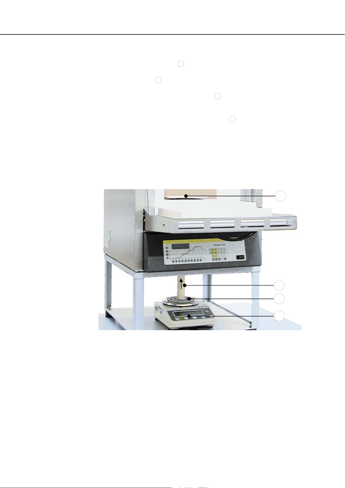
Pos: 140 /TD/Transport_Montage_Inbetriebnahme/Er stinbetriebnahme/Laboröfen - Montage der W aage am L( T).../.../SW-Ofenmodell @ 14\mod_1300119303359_51.doc @ 113570 @ @ 1
Installing the Scale on the L(T).../.../SW Model
Insert the ceramic stamp
1
included in the scope of delivery from below into the
hole in the floor of the furnace.
Place the scale
2
in the frame under the furnace. At the same time raise the pipe
carefully and place it on the supporting surface of the scale.
To hold the pipe in place the support die
3
must be slide into the space between
the pipe and the supporting surface of the scale. This is done by carefully raising
the pipe.
In the furnace chamber, slide the ceramic plate
4
with its guide onto the pipe and
orient it precisely. The pipe must be free-standing on the scale and must not have
any contact with the furnace insulation to avoid falsifying the measurement
results.
Connect the scale with the power plug.
The function of the scale: This information can be found in the instructions
enclosed with the scale.
Separate instruction manual for MV software (optional)
Pos: 141 /=== Seitenumbruch === @ 0\mod_1158819844943_0. doc @ 2983 @ @ 1
4
1
3
2
Fig. 15: Scale
40
Page 41
Pos: 142 /TD/Transport_Montage_Inbetriebnahme/Er stinbetriebnahme/Überschrift - Erstinbetr iebnahme @ 0\mod_1167828977720_51.doc @ 5337 @ 2 @ 1
4.7 Commissioning
Pos: 143 /TD/Transport_Montage_Inbetriebnahme/Er stinbetriebnahme/Erstinbetriebnahme L HT02,04,08 Öfen - 1 @ 2\mod_1186641509092_51.doc @ 20833 @ @ 1
The oven may be put into operation only by qualified persons and in compliance with the
safety instructions.
Read the section on "Safety". When the oven is put into operation, the following safety
information must also be observed to prevent serious injury, damage to the oven, and
damage to other property.
Make sure that the instructions and information in the controller instructions are observed
and followed.
The oven may be used only for its intended purpose.
Ensure that only authorized persons remain in the working area of the oven and that no
other persons are put at risk when the oven is put into operation.
Before starting the oven for the first time, make sure that all tools, foreign parts, and
transportation securing equipment have been removed.
Activate all safety equipment (power switch, emergency stop button if applicable) before
putting the oven into operation.
Incorrectly wired connections may destroy electric/electronic components.
Observe the special protective measures (e.g. grounding, …) for components that are at
risk.
Faulty connections can cause the oven to start unexpectedly.
Before you switch on the oven, make sure that you know what to do in case of faults or
emergencies.
Before starting the oven for the first time, check the electrical connections and control
displays.
Before placing materials in the oven, check whether they could harm or destroy the
insulation or the heating elements. Materials that could damage the insulation include:
alkalis, alkaline earths, metal vapors, metal oxides, chlorine compounds, phosphorous
compounds, and halogens.
Pos: 144 /TD/Allgemeine Hinweise (für alle Anleitungen) /Hinweis - Vor Inbetriebnahme des Ofens sollte die ser 24 Stunden am Aufstellungsort akklimatisiert .. @ 3\mod_1195568014336_51.doc @ 27871 @ @ 1
Note
Before starting the oven for the first time, allow it to acclimatize at its installation location
Pos: 145 /TD/Transport_Montage_Inbetriebnahme/E r stinbetriebnahme/Überschrift - Empfehlun g f ür das erste Aufheizen des Ofens @ 0\mod_1167829134269_51.doc @ 5346 @ 2 @ 1
for 24 hours.
4.8 Recommendations for Heating the Oven for the First Time
Pos: 146 /TD/Transport_Montage_Inbetriebnahme/E r stinbetriebnahme/Empfehlung für das erste Aufh eizen des Laborofens L-LE-L(T)-LV(T)-SKM-SW- HA @ 14\mod_1300196013048_51.doc @ 113620 @ @ 1
The furnace must first be heated up to dry out the masonry and generate a
protective oxidated layer on the heating elements.
During the heating up the furnace may give off unpleasant odors, which is due to
the release of binding agents from the insulation material. We recommend that the
furnace location be well ventilated during the first warm-up phase.
Warm up the empty furnace over a period of roughly 6 hours
°F). Hold this temperature for roughly 1 hour.
Warm up LE …/… models to 1000 °C (1832 °F) (without the warm-up ramp).
After the first warm-up phase, let the furnace cool down naturally to room
temperature.
The furnace is now ready to operate
1) Warm-up ramp
1)
to 1050 °C (1922
41
Page 42

Caution
This procedure must be performed at the time the furnace is commissioned,
following the replacement of heating elements or to regenerate the oxidated layer.
Pos: 147 /TD/Betrieb_Bedienung/Überschrif t - Beschickung/Chargierung @ 0\mod_1167835476044_51. doc @ 5418 @ 2 @ 1
4.9 Loading/charging
Pos: 148 /TD/Transport_Montage_Inbetriebnahme/E r stinbetriebnahme/Beschickung des Laborofens L- LE-L(T)-LV(T)-SKM-SW-HA @ 14\mod_1300202800375_ 51. doc @ 113716 @ @ 1
Charging the Furnace
The insulation is made of high-quality refractory material but is highly sensitive to
impact. Avoid contact when charging to prevent any damage.
To obtain a temperature distribution which is as uniform as possible it is
advantageous to leave space between the pieces and between the pieces and the
side walls. Nabertherm supplies insert plates (base plate) and the like to help you
make use of the furnace chamber.
Loading a very large quantity of ware into the furnace chamber can substantially
lengthen the heating-up time.
The furnace heating system is interrupted if the door is opened. After the door is
reclosed, it is automatically switched on again (not applicable to LE …/… models).
If it can be at all avoided, do not open the furnace when it is hot. When it is
necessary to open the furnace at a high temperature, the time should be kept to an
absolute minimum. Make sure that operators wear the appropriate protective
clothing and that the workspace is adequately ventilated.
Always make sure that the door is completely closed.
Stainless steel sheet can discolor (especially if the furnace is opened while hot).
This does not impair functionality in any way. This is no reason for a complaint.
Caution LE …/… Models:
Continuous operation at maximum temperature can lead to increased wear of the
heating elements and the door seal. We recommend operating at approx. 50 °C
below the maximum temperature.
Caution for LT …/…HA Models:
The recirculating air motor starts when the program begins and cuts out again
automatically when the program ends and the furnace chamber temperature has
dropped to below 80 °C (176 °F). Above this temperature the furnace must not be
switched off or disconnected from its power source. If this caution is not observed
the recirculating air motor may be damaged.
Pos: 149 /TD/Transport_Montage_Inbetriebnahme/E r stinbetriebnahme/Risse in der Isolierung und an den sei tlichen keramischen Platten @ 14\mod_13001987861 91_5 1.doc @ 113693 @ @ 1
42
Warning - Danger of Electric Shock!
For the protection of the operator and the furnace the heating program must be
stopped before the furnace is loaded. Ignoring this warning can result in electric
shock.
Cracks in the insulation
The insulation of the furnace and/or the side heating plates in the furnace
(depending on the furnace model) are made of very high-quality refractory material.
Thermal expansion causes cracks in the insulation even after only a few warm-up
cycles and, in some circumstances, in the side heating plates as well. But these
have no impact on the function or quality of the furnace. This is no reason for a
complaint.
Page 43

Pos: 150 /TD/Betrieb_Bedienung/Zulufthebel für Hubtür- und Klapptürmodellen mit Katalysator-Abluf tgebläse und LV-Modelle - 2 @ 3\mod_1188983024989_51.doc @ 21131 @ @ 1
D
Pos: 151 /=== Seitenumbruch === @ 0\mod_1158819844943_0. doc @ 2983 @ @ 1
Before After
Fig. 16: Example: Cracks in the insulation after a few warm-up cycles.
Notice for the Use of Catalytic Converters and Exhaust Vent Fan:
The air feed lever must always be set to because the exhaust gases cannot be
adequately vented from the furnace chamber.
Information for LV/LVT …/… Models:
These models have an independent, air feed system which cannot be regulated.
The fresh air is fed through holes in the back wall into the upper heating plate
where it is pre-heated and comes back out in front, above the furnace chamber. In
the setting of the air feed lever fresh air is also fed in which is not pre-heated.
For complete feed air pre-heating select the
connection/operation the lever must be set to
setting. During protective gas
.
43
Page 44

Pos: 152 /TD/Betrieb_Bedienung/Überschrif t - Bedienung 1 @ 3\mod_1186740685002_51.doc @ 20988 @ 1 @ 1
5 Operation
Pos: 153 /TD/Betrieb_Bedienung/Überschrif t - Bedienung - Controller B 180/P 330 1.1 @ 9\mod_1249568365976_51.doc @ 64713 @ 2 @ 1
5.1 Operating Controller B 180/P 330
Pos: 154 /TD/Betrieb_Bedienung/Bedienung Laborof ens L-LE-L(T)-LV(T)-SKM-SW-HA ... Controller B180/ P330 @ 14\mod_1300204429027_51.doc @ 113799 @ @ 1
OFF/ON
Fig. 17: Example: Controller
1. The control power is switched on and off with the power switch (1). When
the control voltage is switched on the heating space temperature is displayed by
the controller (2) in the LED.
2. The desired heating and cooling program is set at the controller (2). The
description of the controller is in a separate instruction manual.
3. Temperature value of the over-temperature limit controller (3) (optional) must
be set 30 °C higher than the setting on the controller. Description of the overtemperature limit controller (OTLC) is contained in the instruction manual of
the controller B 180/P 330.
2
3 (optional)
2132iEurotherm
27x12,7
1
Pos: 155 /=== Seitenumbruch === @ 0\mod_1158819844943_0. doc @ 2983 @ @ 1
Caution
Continuous operation at maximum temperature can lead to increased wear of the
heating elements and the door seal. We recommend operating at approx. 50 °C
below the maximum temperature.
Caution
Description of the controller B 180/P 330 is contained in a separate instruction
manual.
44
Page 45
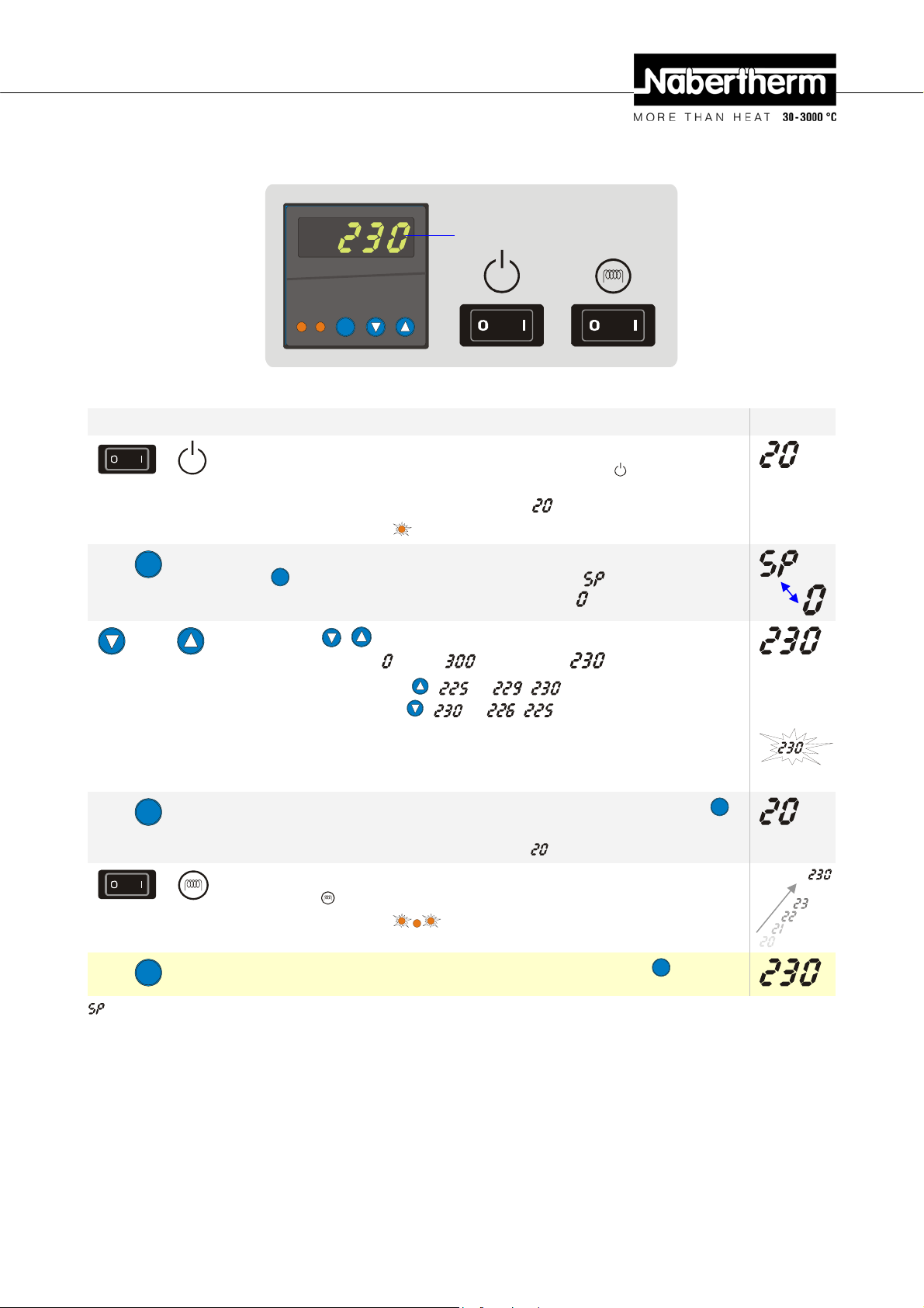
Pos: 156 /TD/Betrieb_Bedienung/Überschrif t - Bedienung - Controller R6 1.1 @ 9\mod_1249568510166_51.doc @ 64730 @ 2 @ 1
5.2 Operating Controller R 6
Pos: 157 /TD/Betrieb_Bedienung/Bedienung Control ler R6 @ 9\mod_1249472399873_51.doc @ 64633 @ @ 1
Display
K1 K2
P
Fig. 18: Controller R 6
Key Description Display
Switch on oven I
OFF/ON
The oven is switched on and off with the power switch "
power is switched on, the current oven temperature (actual temperature) is
shown on the controller display (Example:
When the K1 lamp "
" remains on, this means that the controller is ready.
°C).
". When the
To adjust the required oven temperature (temperature set point), press the
Press P
"P" button once. The display alternates between " " and the last
temperature set point in the entry level (Example: °C)
Press
Use the "
set point) between
Increase the value with
Reduce the value with
Wait 2 seconds until the new temperature set point is integrated automatically (display flashes
1x)
(For the required temperature set point you can choose a temperature range from 5°C above
room temperature to 300°C).
" buttons to set the required oven temperature (temperature
°C and °C (Example: °C)
( … , )
( … , )
Press P
(or the display changes
automatically after 15 seconds)
OFF/ON
Press P
= Set point
Pos: 158 /=== Seitenumbruch === @ 0\mod_1158819844943_0. doc @ 2983 @ @ 1
The display changes automatically after 15 seconds or if you press the "P"
button again
(The current oven temperature is displayed. Example °C).
Switch on heating I The heating process is started.
Use the "
When the K2 lamp "
" switch to switch the heating on and off.
" flashes, this means that the heating is ready.
You can check the temperature set point at any time with the "P" button.
45
Page 46
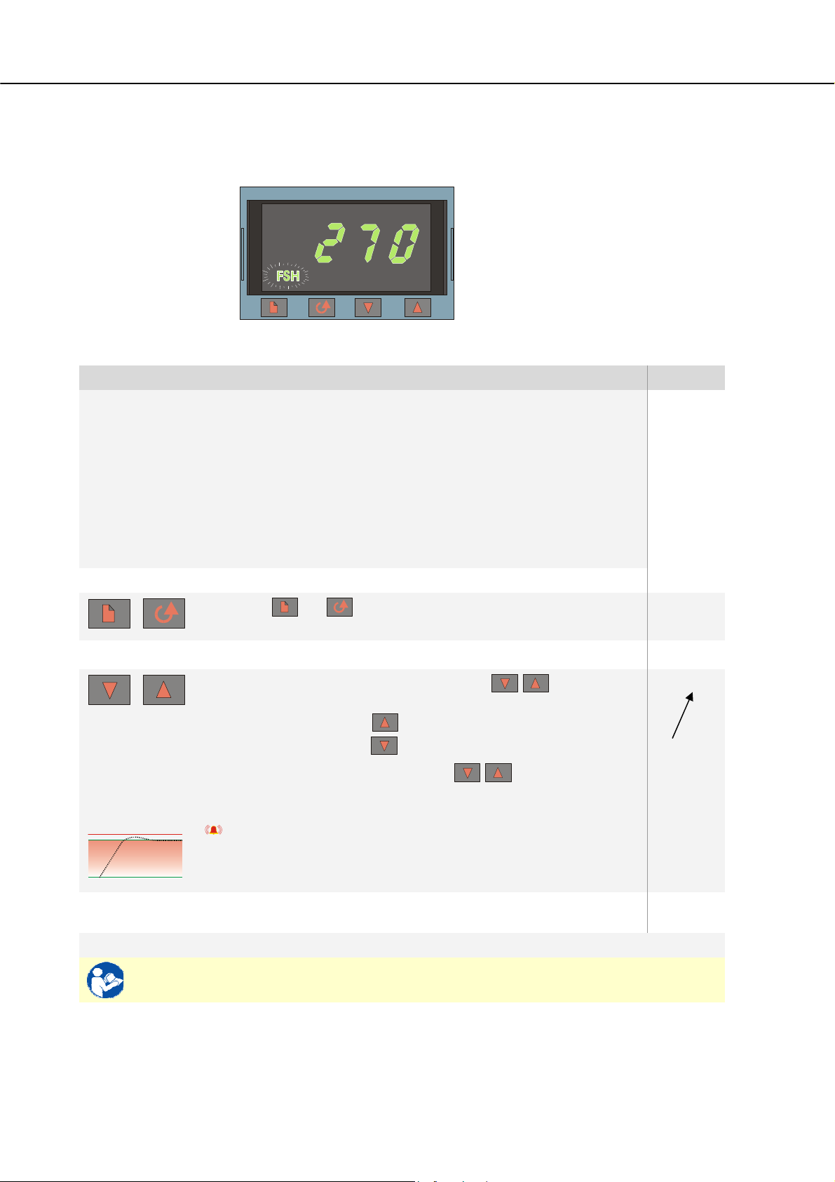
Pos: 159 /TD/Betrieb_Bedienung/Überschrif t - Temperaturwählbegrenzer mit einstellbarer Abschal ttemperatur 1.1 @ 9\mod_1250158374029_51.doc @ 65123 @ 2 @ 1
5.3 Over-Temperature Limit Controller with Manual Reset and Adjustable Cut-Off
Temperature
Pos: 160 /TD/Betrieb_Bedienung/Bedienung Tempera tur wählbegrenzer (TWB) Eurotherm 2132i @ 10\mod_125302 5652 302_51.doc @ 65993 @ @ 1
2132i
Fig. 19: Over-temperature limit controller with manual reset 2132i
Key Description Display
The over-temperature limit controller with manual reset monitors the
temperature in the oven chamber. The display shows the last trigger
temperature that was set. If the temperature in the oven chamber
exceeds the set trigger temperature, the heating is switched off to
protect the oven and the load. "FSH" alarm flashes on the overtemperature limit controller.
When the temperature in the oven chamber falls below the value set
on the over-temperature limit controller , the following buttons have
to be pressed to release the heating so that the oven can continue to
operate:
Release heating:
Press and simultaneously. The alarm on the overtemperature limit controller is reset and this releases the heating.
Adjust the trigger temperature:
Set the required trigger temperature with the button
270 °C
260 °C
(Example 270 °C)
Increase the value with (260 … 269, 270)
Reduce the value with (270 … 261, 260)
To change the value quickly: hold the button depressed for
longer.
Wait 2 seconds until the new trigger temperature is integrated automatically (display
flashes 1x).
Note:
Premature triggering of the over-temperature limit controller can be avoided if the
difference between the adjustable temperature in the oven chamber and the trigger
temperature is not below 10°C.
260 °C
FSH
270
260
The display jumps back to the start screen showing the trigger
temperature. The current trigger temperature is displayed.
Entry finished.
For more information about operation, see the separate instructions for the
Pos: 161 /TD/Sicherheit/Sicherheitssymbole/W arnhinweise-ISO-ANSI/Warnsymbol_Achtung - Einstellung am TWB/TWW - Piktogramm Gebotszeichen ! @ 9\mod_12475 72076550_51.doc @ 63296 @ @ 1
46
Eurotherm 2132i
270 °C
Page 47
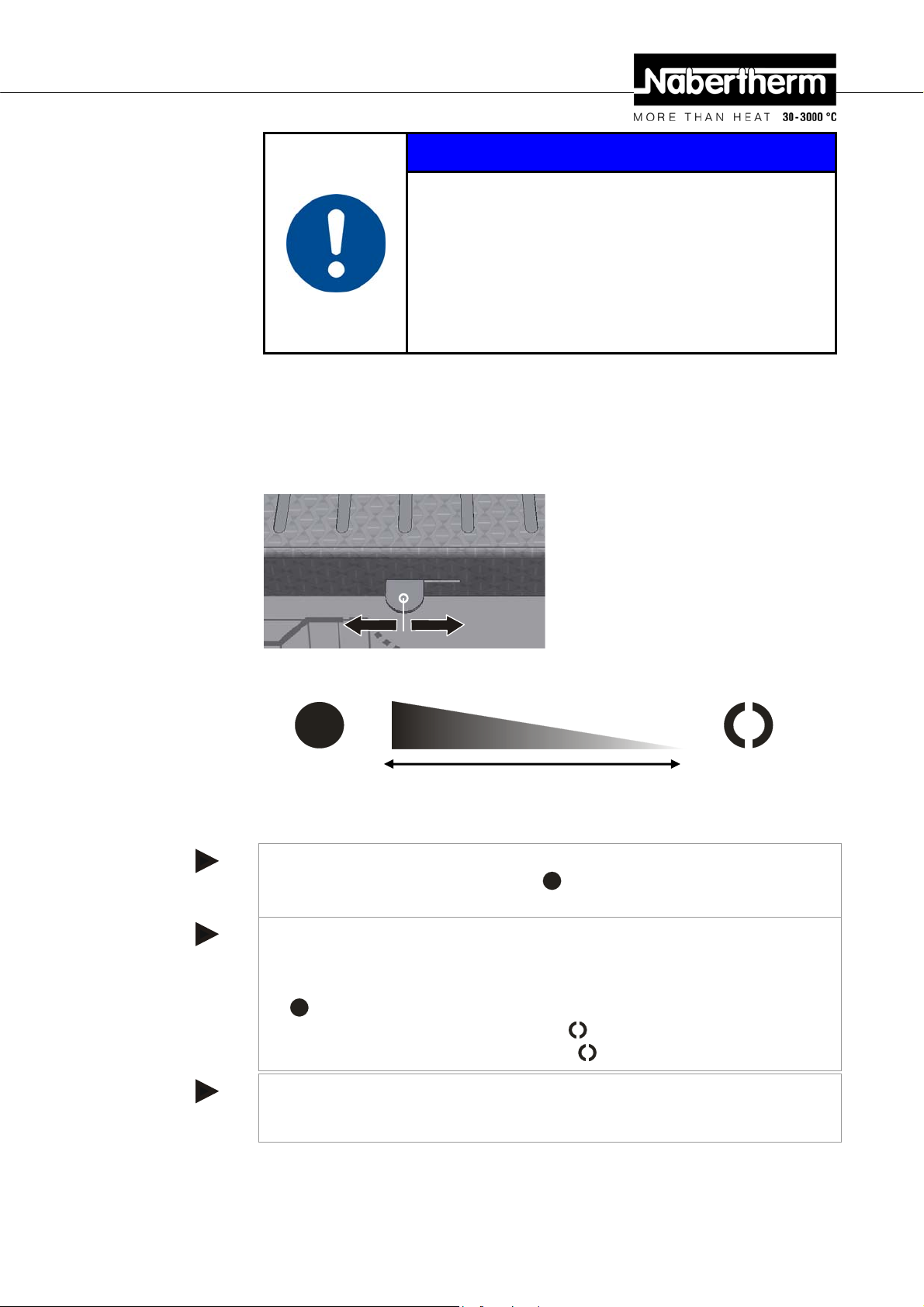
Pos: 163 /TD/Betrieb_Bedienung/Überschrif t - Zulufthebel @ 3\mod_1188982021389_51.doc @ 21118 @ 2 @ 1
5.4 Air Inflow Lever
Pos: 164 /TD/Betrieb_Bedienung/Zulufthebel für Hubtür- und Klapptürmodellen - 1 @ 3\mod_1188977524741_51. doc @ 21106 @ @ 1
D
The volume of air fed to the furnace can be adjusted with the fresh air lever. The fresh air
lever is located at the side of the door at the bottom. The position is explained by the
symbols beside and on the lever.
F
i
g
.
20
:
Fres Fig. 1: Fresh air lever
NOTICE
• Overheating
• Damage to the batch
• If, as a result of excessive heat, a batch is likely to be damaged
by the pre-set response temperature of the over-temperature limit
controller with manual/automatic reset or if the batch itself
becomes a source of danger for the oven or its surroundings, the
temperature setting on the over-temperature limit controller with
manual/automatic reset must be reduced to the maximum
permissible value.
Pos: 165 /TD/Betrieb_Bedienung/Zulufthebel für Hubtür- und Klapptürmodellen mit Katalysator-Abluf tgebläse und LV-Modelle - 2 @ 3\mod_1188983024989_51.doc @ 21131 @ @ 1
D
Pos: 166 /TD/Betrieb_Bedienung/Hinweis - Zulufth ebe l für Hubtür- und Klapptürmodellen - Temperaturgleic hmäßigkeit - 2 @ 12\mod_1283334296574_51.doc @ 97705 @ @ 1
Pos: 167 /=== Seitenumbruch === @ 0\mod_1158819844943_0. doc @ 2983 @ @ 1
Fresh air lever is Fresh air lever is
max. open closed
Fig. 21: Regulating the feed of fresh air (symbols)
Notice for the Use of Catalytic Converters and Exhaust Vent Fan:
The air feed lever must always be set to because the exhaust gases cannot be
adequately vented from the furnace chamber.
Information for LV/LVT …/… Models:
These models have an independent, air feed system which cannot be regulated.
The fresh air is fed through holes in the back wall into the upper heating plate
where it is pre-heated and comes back out in front, above the furnace chamber. In
the setting of the air feed lever fresh air is also fed in which is not pre-heated.
For complete feed air pre-heating select the
connection/operation the lever must be set to
Note
setting. During protective gas
.
If the fresh air lever is open, under certain circumstances this may affect temperature
uniformity in the furnace chamber.
47
Page 48
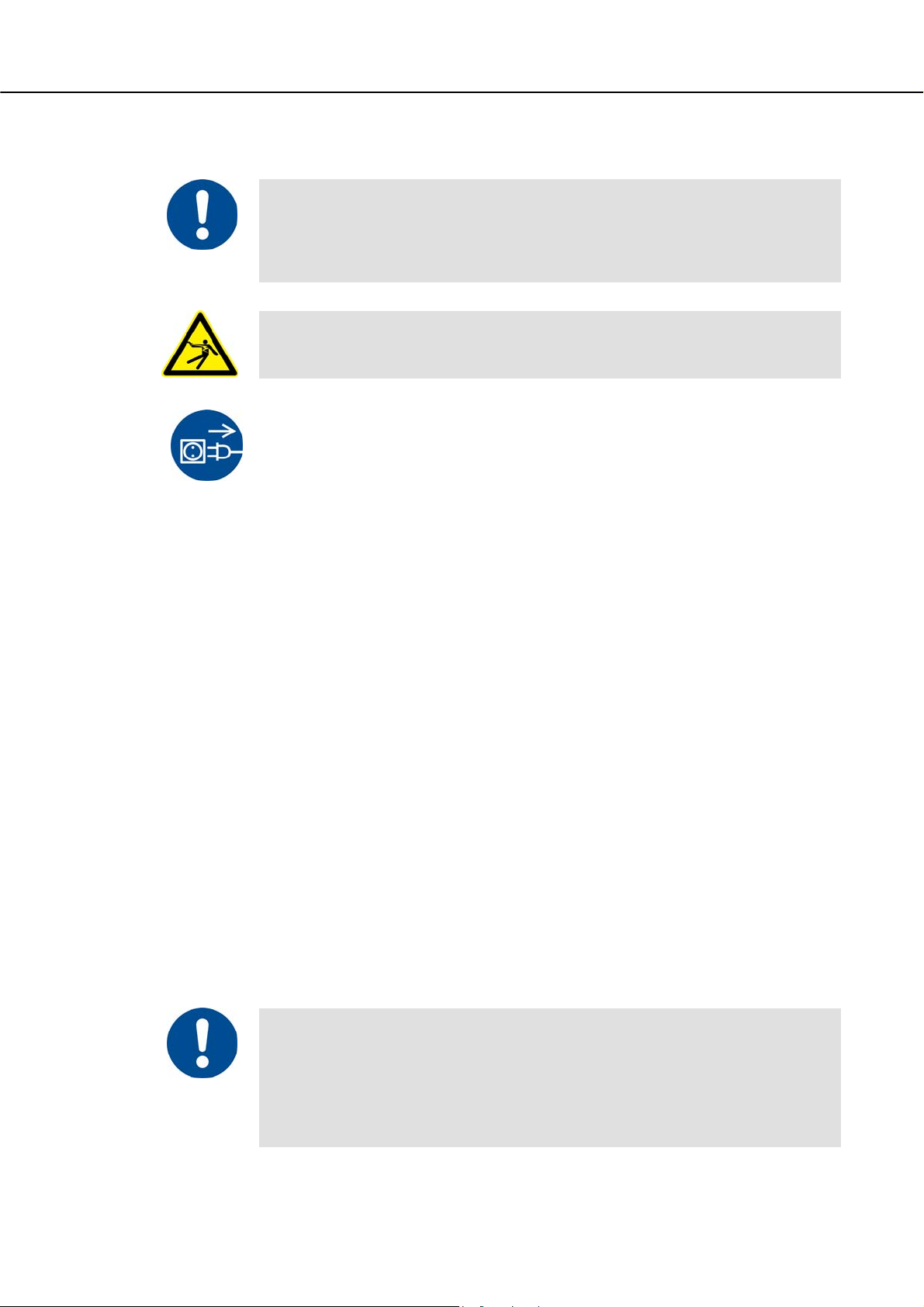
Pos: 168 /TD/Wartung_Reinigung_Instandhaltung/ Überschrift - Wartung, Reinigung und Instandhaltun g @ 0\mod_1167835785730_51.doc @ 5436 @ 1 @ 1
6 Servicing, Cleaning, and Maintenance
Pos: 169 /TD/Wartung_Reinigung_Instandhaltung/ Wartung, Reinigung und Instandhaltung - Laboröfen @ 3\ mo d_11 88908437969_51.doc @ 21071 @ @ 1
Warning! General hazards!
Cleaning, lubrication, and maintenance tasks may only be performed by authorized experts
following the maintenance instructions and accident protection guidelines. We recommend
that maintenance and repair be performed by Nabertherm GmbH Service. Failure to comply
runs the risk of bodily injury, death, or significant property damage!
Pos: 170 /TD/Allgemeine Hinweise (für alle Anleitungen) /Hinweis - Dieser Ofen enthält in der Isolierung ker a misches Fasermaterial. @ 3\mod_1190114970393_51.doc @ 21866 @ @ 1
Warning - danger due to electrical current!
Work on the electrical equipment may only be performed by qualified, authorized
electricians!
During maintenance work, the voltage supply to the furnace and/or switching system must
be switched off to prevent unintentional commissioning. Disconnect the mains power
connector due to reasons of safety.
Operators may only correct malfunctions which are obviously due to operational error!
Wait until the furnace chamber and attaching parts have cooled to room temperature.
The furnace must be visually inspected at regular intervals for damage. The interior of the
furnace must also be cleaned as required (e.g. vacuuming out) Attention: Do not bang
against the heating elements to avoid breaking them.
While work is being performed on the furnace, the furnace and work room must
additionally be ventilated with fresh air.
Safety systems removed during maintenance tasks must be replaced after the work.
Warning of swinging loads in the workshop (e.g. crane systems). Work under a lifted load
(e.g. a lifted furnace or switching system) is not permitted.
Safety switches and any limit switches present must be checked for function periodically
(BGV A3) or according to the national guidelines of the country of operation.
To ensure proper temperature regulation of the furnace, the thermocouple must be checked
for damage before every process.
If necessary, retighten the element holders (see chapter "Replacing the Heating Element").
Before carrying out this work, the voltage supply to the furnace and/or switching system
must be switched off (disconnect mains power connector). The regulations (BGV A3) or
corresponding national regulations in the relevant country of operation must be observed.
There are one or more contactors in the control system. The contacts of these circuit
breakers are wearing parts and must therefore be serviced and/or replaced regularly (BGV
A3) or according to the national guidelines of the country of operation.
The switching system cabinet (if available) contains vent grilles with integrated filter mats.
These must be cleaned and/or replaced at regular intervals in order to ensure sufficient
intake and outflow of air from the switching system. During melting operation, the
switching cabinet door must always be firmly closed.
This furnace contains ceramic fiber material in the insulation.
Active handling of these fibers (e.g., exchange of the insulation) in the Federal Republic of
Germany is subject to the conditions of the Ordinance on Hazardous Substances, Annex V,
No. 7 ("Artificial mineral fibers") of June 12, 1998. In the rest of the European Union,
ceramic fibers are categorized as follows by Directive 97/69/EC of the Commission of
December 5, 1997 CARC. Cat. 2; R 49; Xi R 38. Work with the fiber insulation must
therefore be done in such a way that as little fiber dust as possible is released.
48
Page 49

The following points must be noted when handling ceramic fiber:
- Dust development during processing should be minimized.
- Contact with skin and eyes should be avoided. The effects caused by
fibers on the skin or in the eyes may cause mechanical irritation, as a result of
which reddening and itching may occur.
- When processing large quantities of ceramic fibers, loose work clothing with
long sleeves, gloves and safety glasses should be worn.
- When working with ceramic fiber insulation inside furnaces, a half/quarter mask
with P2 filter should additionally be worn.
The furnace and its operating equipment must be regularly checked in accordance with the
regulations of the employer's liability insurance association (BGV A3) or the corresponding
national regulations in the relevant country of use!
Pos: 172 /TD/Wartung_Reinigung_Instandhaltung/ Überschrift - Stillsetzung der Anlage für War tungsarbeiten @ 0\mod_1167835907715_51.doc @ 5445 @ 2 @ 1
6.1 Shutting the system down for maintenance
Pos: 173 /TD/Wartung_Reinigung_Instandhaltung/ Stillsetzung der Anlage für Wartungsarbeiten - Labor öfen @ 3\mod_1188977196773_51.doc @ 21093 @ @ 1
Warning! General hazards!
Cleaning, lubrication, and maintenance tasks may only be performed by authorized experts
following the maintenance instructions and accident protection guidelines. We recommend
that maintenance and repair be performed by Nabertherm GmbH Service. Failure to comply
runs the risk of bodily injury, death, or significant property damage!
Wait until the furnace chamber and attached parts have cooled to room
temperature
The furnace must be completely emptied.
Notify operating personnel and specify a supervisor.
Switch off the main switch and disconnect the mains power connector.
Lock the main switch and secure against restoration of power using a padlock.
Attach a warning sign on the main switch.
Seal off a large area around the servicing area.
Check for disconnection of power.
Ground and short-circuit the working area.
Cover any nearby parts still under power.
Pos: 174 /TD/Ersatz-/Verschleißteile/W ar nung - Gefahren durch elektrischen Strom - für alle Öfen @ 3\mod_1189491 390787_51.doc @ 21273 @ @ 1
Pos: 175 /=== Seitenumbruch === @ 0\mod_1158819844943_0. doc @ 2983 @ @ 1
Warning! General hazards!
Do not touch any object without first checking its temperature.
Warning - Danger of Electric Shock!
Work on the electrical equipment may be done only by qualified, authorized electricians.
During maintenance work it must be ensured that the oven and the switching equipment
cannot be activated by mistake (pull out the power plug) and that all moving parts in the
oven are secured. Observe BGV A3 or the corresponding national regulations in the
country where the oven is installed. Wait until the oven and the connected parts have
cooled to room temperature.
49
Page 50

Pos: 176 /TD/Wartung_Reinigung_Instandhaltung/ Überschrift - Regelmäßige Wartungsarbeiten am Ofen @ 0\ mod_1167836306681_51.doc @ 5463 @ 2 @ 1
6.2 Regular Maintenance of the Oven
Pos: 177 /TD/Wartung_Reinigung_Instandhaltung/ Regelmäßige Wartungsarbeiten (Wartungstabelle) HTC 01/15 - Renishaw @ 10\mod_1255433729380_51.doc @ 67002 @ @ 1
Position/
Maintenance Point
Day Week Month Quarter Year Personnel
Safety test in accordance
with BGV A3 or
corresponding national
regulations
Safety and
limit switches
(if available)
Furnace chamber, flue
outlets and flue
Seal surfaces:
door lining/furnace lining Visual check
Heating elements Visual check (visible
Check for even power
consumption of heating
Thermocouple Visual check (visible
Set setpoint Test according to work
Measure Maintenance Interval Operating Qualifi
According to
regulations
Function test
Clean and check for
damage, vacuum out
carefully
part of the heating
element in the furnace
chamber)
Function test
part of the
thermocouple in the
furnace chamber)
schedules
According to regulations
●
x
x
■ x
●
●
●
●
x
x
●
x
x
x
ed
Key: ■ = clean ● = check, replace x = performance by
Fig. 22: Maintenance table
Pos: 178 /TD/Allgemeine Hinweise (für alle Anleitungen) /Warnung - Arbeiten an der elektrischen Ausrüstung dür fen nur von ... @ 2\mod_1184228021019_51.doc @ 19673 @ @ 1
Warning - Danger of Electric Shock!
Work on the electrical equipment may be done only by qualified, authorized electricians.
Pos: 179 /TD/Allgemeine Hinweise (für alle Anleitungen) /Hinweis - Wartungsarbeiten dürfen nur von autori sierten Fachpersonen unter Beachtung von ... @ 1\mod_1173971704689_51.doc @ 11131 @ @ 1
Note
Maintenance work must be performed by authorized personnel following the maintenance
instructions and the accident prevention regulations. We recommend that the maintenance
and repair work be carried out by the service team of Nabertherm GmbH.
Pos: 180 /TD/Wartung_Reinigung_Instandhaltung/ Überschrift - Betrieb- und Hilfsmittel @ 0\mod_1167 837161458_51.doc @ 5499 @ 2 @ 1
6.3 Operating and Auxiliary Materials
Pos: 181 /TD/Wartung_Reinigung_Instandhaltung/ Überschrift - Reinigungsmittel 1.1 @ 0\mod_1167837 229 988_51.doc @ 5508 @ 2 @ 1
6.4 Cleaning Products
Pos: 182 /TD/Wartung_Reinigung_Instandhaltung/ Reinigungsmittel (für alle Öfen) @ 0\mod_115865759 2397 _51.doc @ 2843 @ @ 1
Follow the procedure for shutting down the furnace system (in the "Operation"
section). Then the power plug must be pulled out of the socket. Wait until the
furnace cools down naturally.
Use commercially available detergent which is either water-based or noncombustible and free of any solvents to clean the housing of any deposits; use a
vacuum cleaner for the interior.
50
Page 51

Follow the labeling and the instructions on the packaging of the detergent.
Wipe the surface with a damp, lint-free cloth. The following detergents can also be
used:
This list must be completed by the operator.
Pos: 183 /TD/Sicherheit/Sicherheitssymbole/W arnhinweise-ISO-ANSI/Warnsymbol_Gefahr - Gefahren beim Reinigen - Piktogramm Elektr.-Netzstec ker-Spritzen @ 9\mod_1247825736695_51.doc @ 63802 @ @ 1
Component and
Detergent
location
Outer surfaces
(frames *)
Outer surface
Use commercially available detergent which is either wateror non-combustible and free of any solvents for cleaning *)
Stainless still cleaner
(stainless steel)
Interior Carefully clean with a vacuum cleaner
(avoid the heating elements)
Insulation
materials
Door seal
(if included)
Carefully clean with a vacuum cleaner
(avoid the heating elements)
Use commercially available detergent which is either wateror non-combustible and free of any solvents for cleaning
Instrument panel Wipe the surface with a damp, lint-free cloth. (e.g. glass
cleaner)
You must be sure that the cleaner does not damage the water-soluble and, hence,
*)
environmentally safe paint (the clear should be tried first on an interior, normally unseen
location).
Fig. 23: Detergent
Do the cleaning from beginning to end without breaks to protect the surfaces.
Remove the detergent completely from the surfaces by wiping them with a damp,
lint-free cloth.
After cleaning all the supply lines, check all the connections for leaks, loose
connections, abrasion and damage; report any shortcomings found immediately!
Please follow the section entitled "Environmental Protection Rules and
Regulations"
Caution
The furnace, the furnace chamber and attached components must NOT be
cleaned using a high-pressure cleaner.
DANGER
Pos: 184 /=== Seitenumbruch === @ 0\mod_1158819844943_0. doc @ 2983 @ @ 1
• Danger of electric shock.
• Risk of fatal injury
• Before cleaning, pull out the power
plug.
• Do NOT pour water or cleaning
products over the inside or outside
surfaces
• Allow oven to dry completely before
operating it again
51
Page 52

Pos: 185 /TD/Störungen/Fehlersuche/Öfen/Übersc hrift - Störungen @ 0\mod_1167837724781_51.doc @ 5526 @ 1 @ 1
7 Faults
Pos: 186 /TD/Störungen/Fehlersuche/Öfen/Stör ungstabelle Ofen (allgemeine Hinweise) @ 1\mod_1171363 750459_51.doc @ 9646 @ @ 1
Pos: 187 /TD/Störungen/Fehlersuche/Öfen/Stör ungstabelle Laborofen LHT-Tischmodell @ 4\mod_1205479 967638_51.doc @ 34312 @ @ 1
Type of fault Possible causes Fault rectification
Work on the electrical system may be done only by qualified, authorized electricians.
Operators may only rectify faults that are obviously due to operating errors.
Call the local electrician for faults that you cannot localize.
If you have any questions, problems, or requirements, contact Nabertherm GmbH. By mail,
phone, or e-mail See "Nabertherm Service".
Controller does not switch on. -No voltage available.
-Controller defective.
Controller indicates fault. -See separate instructions for
controller.
No heating chamber heating after
starting program.
-Error in program input.
-Connection fuse(s) defective.
-Heating element defective
Very slow heating chamber
-Connection fuse(s) defective. -Check connection fuse(s),
heating.
Selected end temperature is not
reached.
Pos: 188 /=== Seitenumbruch === @ 0\mod_1158819844943_0. doc @ 2983 @ @ 1
-Lack of heater output due to
undervoltage.
-Heating element defective
-Check connection fuse(s),
renew if necessary.
-Check controller fuses (if
available), renew if necessary.
-Check plug connector.
-See separate instructions for
controller.
-Check heating program (see
separate instructions for controller)
-Check connection fuse(s),
renew if necessary.
Notify
Nabertherm Service if the new
fuse trips on screwing in.
-Have checking carried out by
Nabertherm Service.
renew if necessary.
Notify Nabertherm Service if the
new fuse trips on screwing in.
-Have checking carried out by
Nabertherm Service.
52
Page 53

Pos: 189 /TD/Ersatz-/Verschleißteile/Übersc hrift - Sicherung austauschen 1.1 @ 9\mod_12496280904 92_5 1.doc @ 64803 @ 2 @ 1
7.1 Replacing a Fuse
Pos: 190 /TD/Ersatz-/Verschleißteile/Sic herung austauschen - Version A mit Werkzeug @ 9\mod_1249897945 401 _51.doc @ 64903 @ @ 1
A fuse is located on the back of the oven beside the power cable connection. The fuse is an
important component of the power supply system and protects the oven and its components
against damage and fire. When you insert a new fuse, make sure that the fuse rating is
suitable for the voltage used by your oven.
Carry out the procedure to switch off the oven (see "Operation"). Then pull the power plug
out of the socket.
NOTICE
• Damage to the oven and its components
• Use of a fuse that is NOT suitable for the respective voltage
may damage the oven and its components and is a fire
hazard.
• Use only a suitable fuse type. Check that the fuse type has the
correct nominal current value.
Fuse holder
Fig. 24: The fuse is located in the back wall of the oven.
Insert a suitable flat blade screwdriver into the slot of the fuse holder. To remove
the fuse holder, press it in and turn it anti-clockwise. After a few turns, pull the
fuse holder out carefully with your fingertips.
Fig. 25: Release and pull out the fuse holder
Remove the fuse from the fuse holder.
Replace the defective fuse with a similar fuse.
Before you replace the fuse, make sure that it has the correct nominal current. For
the correct fuse (fuse link), see "Spare/Wearing Parts".
53
Page 54

Fuse (fuse link)
T 16 A
H 500V
Nominal current
(Example)
Fig. 26: Remove fuse
Note
The nominal current is engraved into the metal cap of the fuse or can be found imprinted
directly on the fuse.
Insert the new fuse into the fuse holder. Make sure that the fuse is pushed fully
into the holder.
Replace the fuse holder slowly and carefully. To fix the fuse holder, insert the flat
blade screwdriver into the slot and turn it in a clockwise direction with some
pressure.
T 16 A
H 500V
Fig. 27: Insert fuse
Check that the power cable is not damaged. The power cable must not be
damaged. Power cables may be replaced only with similar, approved cables.
Reconnect the power cable (see "Connecting the Oven to the Power Supply")
Switch on the oven's power switch (see "Operation")
Pos: 192 /TD/Betrieb_Bedienung/Überschrif t - Snap-In-Kupplung (Stecker) vom Ofengehäuse trennen 1.1 @ 12\ m od_1 282113872192_51.doc @ 96923 @ 2 @ 1
7.2 Separate the Snap-In Coupling (Plug) from the Furnace Housing
Pos: 193 /TD/Betrieb_Bedienung/Bedienung Snap- I n-Kupplung (Stecker) vom Ofengehäuse trennen @ 12\mod_1282 114156861_51.doc @ 96945 @ @ 1
With a small flat blade screwdriver carefully push the locking latch 1 upward while
2
pulling the plug
out of the coupling 3.
1
3
2
Pos: 194 /=== Seitenumbruch === @ 0\mod_1158819844943_0. doc @ 2983 @ @ 1
54
Fig. 28: Separate the snap-in coupling (plug) from the furnace housing
Page 55

Pos: 195 /TD/Ersatz-/Verschleißteile/Übersc hrift - Ersatz-/Verschleißteile @ 0\mod_11641252 52056_51.doc @ 4243 @ 1 @ 1
8 Spare Parts/Wearing Parts
Pos: 196 /TD/Ersatz-/Verschleißteile/Ersatz- /Verschleißteile allgemeiner Text -Ersatz teile bestellen-Verfügbarkeit von Ersatz- und Ver sc h @ 13\mod_1290428577708_51.doc @ 108720 @ @ 1
Ordering Spare Parts:
Our Nabertherm Service team is available to you all around the world. Due to our
considerable production depth we deliver most spare parts from the warehouse
overnight or can make them ready for delivery within short deadlines. You can
order Nabertherm spare parts easily and simply directly from the factory. If you
cannot find the spare part you want we will be glad to help you. Spare parts can be
ordered in writing, by phone or on the Internet -> see the section entitled
"Nabertherm Service".
Availability of Spare Parts and Wearing Parts:
Although Nabertherm has many spare parts and wearing parts on stock, we cannot
guaranty the short-term availability of all of them. We recommend that certain parts
be ordered in advance. If you need any assistance when selecting spare parts and
Pos: 197 /TD/Ersatz-/Verschleißteile/Ersatz teilliste - Laborofen L-LE-L(T)-LV(T)-SKM-SW -HA @ 14\mod_1300284991707_51.doc @ 113846 @ @ 1
Model
No. Designation
1 Furnace
1.3 Fiber wool
1.2
2 Electrical/controllers
2.1 Controller P 330
2.2 Controller P 180
2.3 Controller R 6
2.4 Rocker switch
2.5 G back-up set 2 A
2.6 G back-up set 10 A
2.7 G back-up set 16 A
Power cable
2.8
(xx = country code required)
3 Tools
wearing parts, the staff at Nabertherm will be glad to set aside time for you.
Part number
691600518 *)
520100258
520100257
635001141
541700200
541500182
541500215
541500303
V0013xx
*) = Quantity depending on need
Pos: 198 /TD/Ersatz-/Verschleißteile/Legende f ür Ersatzteile Trockenschrank @ 10\mod_125257851 0636 _51.doc @ 65905 @ @ 1
Symbols
Can be replaced by the customer with tools and instructions.
Can be replaced by trained personnel with tools and instructions.
Pos: 199 /TD/Ersatz-/Verschleißteile/Hinwei s - Originalteile und Zubehör sind speziell für Naber ther m-Ofenanlagen ... @ 8\mod_1242719812994_51.doc @ 56963 @ @ 1
Pos: 200 /TD/Ersatz-/Verschleißteile/Für den Aus- und Einbau von Ersatz-/Verschleißteilen, wenden Si e sich an unseren Nabertherm-Service. @ 4\mod_120403 4379624_51.doc @ 31716 @ @ 1
Pos: 201 /=== Seitenumbruch === @ 0\mod_1158819844943_0. doc @ 2983 @ @ 1
NT Nabertherm Service required
Note
Original parts are designed especially for Nabertherm ovens. Replace parts only with
original Nabertherm parts. Otherwise the warranty will be void. Nabertherm accepts
absolutely no liability for damage caused by using parts that are not original Nabertherm
parts.
Note
Contact our Nabertherm Service for removing and installing replacement and wear parts.
See section on "Nabertherm Service". Work on the electrical equipment may only be
performed by qualified and authorized specialist electricians. This applies also to repairs
not described below.
55
Page 56

Pos: 202 /TD/Service/Nabertherm-Service @ 0\mod_1 1586 58915997_51.doc @ 2861 @ 1 @ 1
9 Nabertherm Service
Contact Nabertherm Service at any time for maintenance and repair.
If you have any questions, problems, or requirements, contact Nabertherm GmbH. By mail,
phone or e-mail.
Mail
Nabertherm GmbH
Bahnhofstrasse 20
28865 Lilienthal/Germany
Phone or Fax
Phone: +49 (4298) 922-0
Fax: +49 (4298) 922-129
Pos: 203 /TD/Service/Typenschild geklebt für elektr i sch beheizte Produkte @ 14\mod_1298369786322_51.doc @ 112503 @ @ 1
Pos: 205 /TD/Betrieb_Bedienung/Controller/ B150/ B130/B170/C280/C290/C295/P320/Schaltplä ne/Überschrift - Elektrischer Anschluss (Schal tplan) @ 0\mod_1169476874919_51.doc @ 7492 @ 1 @ 1
Web or e-mail
www.nabertherm.com
contact@nabertherm.com
When you contact us, please have the type plate details of the oven or controller at
hand.
Provide the following details from the type plate:
1
Kiln model
Serial number
2
Article number
xxxxxxxxxxx
xxxxxxxxxxx xxxx °C 20xx
xxx V x/N/PE~ xx.x A 50/60 Hz x.x kW
www.nabertherm.de Made in Germany
1
3
SN xxxxxx
3
2
Year of construction
4
4
Fig. 29: Example (type plate)
10 Electrical Connections (Circuit Diagram)
Pos: 206 /TD/Betrieb_Bedienung/Den Schaltplan zu di eser Anlage finden Sie im beigefügtem Anhang @ 7\mod_12327081 369 48_51.doc @ 48393 @ @ 1
Note
See the Appendix for the wiring diagram for this system.
Pos: 207 /=== Seitenumbruch === @ 0\mod_1158819844943_0. doc @ 2983 @ @ 1
56
Page 57

Pos: 208 /TD/Außerbetriebnahme_Demontage_Lagerung _Rücktransport/Überschrift - Außerbetri ebnah me, Demontage und Lagerung @ 0\mod_1167838295210_51. doc @ 5580 @ 1 @ 1
11 Shut-Down, Dismantling, and Storage
Pos: 209 /TD/Sicherheit/Überschrift - Umweltschut zvorschriften @ 0\mod_1167826189237_51.doc @ 5202 @ 2 @ 1
11.1 Environmental Regulations
Pos: 210 /TD/Sicherheit/Umweltschutzvorschr iften Elektronische Bauteile-Isolierung-Al tmetall @ 4\mod_1205143314853_51.doc @ 32563 @ @ 1
When it is delivered, this oven contains no substances that make a hazardous waste
classification necessary. However, residues of process materials may accumulate in the
oven insulation during operation. These may be hazardous to health and/or the
environment.
Dismantle the electronic components and dispose of them as electric scrap.
Remove the insulation and dispose of it as hazardous waste (See Servicing,
Cleaning, and Maintenance with Ceramic Fiber Material)
Dispose of the housing as scrap metal.
Pos: 211 /TD/Allgemeine Hinweise (für alle Anleitungen) /Hinweis - Nationalen Vorschriften des jeweili gen Ver wendungslandes sind zu beachten. @ 10\mod_1258644 986266_51.doc @ 68881 @ @ 1
Note
Observe the national regulations of the country in which the kiln will be used.
Pos: 212 /=== Seitenumbruch === @ 0\mod_1158819844943_0. doc @ 2983 @ @ 1
57
Page 58

Pos: 213 /TD/Außerbetriebnahme_Demontage_Lagerung _Rücktransport/Hinweise für den Rücktransport d er Ofen-Anlage @ 4\mod_1202459053863_51.doc @ 30918 @ 2 @ 1
11.2 Transportation/Return Transportation
If you still have the original packaging, this is the safest way to send an oven.
Otherwise:
Choose suitable, adequately sturdy packaging. During transportation, packages are often
stacked, bumped, or dropped; the packaging acts as external protection for your oven.
+45
-5°C
- Drain all piping and containers before transportation/return transportation
(e.g. cooling water). Pump off operating materials and di spose of properly.
- Do not subject the oven to extreme cold or hot temperatures (direct sunlight).
Storage temperature -5°C to 45 ° (-23°F to 113°F )
Humidity 5% to 80%, non condensing
- Place the oven on a level floor to prevent distortion.
- Packaging and transportation may be carried out only by qualified and
authorized persons
If your oven has transportation securing equipment (see "Transportation Securing
Equipment"), use this.
Otherwise, in general:
"Fix" and "secure" (adhesive tape) all moving parts and cushion and protect any projecting
parts against breakage.
Protect your electronic equipment against moisture and make sure that no loose packaging
material can get inside it.
Fill gaps in your packaging with soft but adequately firm material (e.g. foam mats) and
make sure that the equipment cannot slide around in the packaging.
If the goods are damaged during return transportation due to inadequate packaging
or some other breach of duty, the costs will be borne by the customer.
As a rule:
The oven is sent without accessories, unless the technician expressly requests them.
Enclose a detailed description of the fault along with the oven – this saves the technician
time and costs.
Don't forget to enclose the name and phone number of a contact in case there are any
questions.
Pos: 214 /=== Seitenumbruch === @ 0\mod_1158819844943_0. doc @ 2983 @ @ 1
58
Note
Return transportation may only be carried out according to the information given on the
packaging or in the transportation documents.
Note
Transportation and return transportation not covered by a warranty claim are paid for by
the customer.
Page 59

Pos: 215 /TD/Anhang/Überschrift - Konformitätserk lärung @ 2\mod_1186581095030_51.doc @ 20795 @ 1 @ 1
12 Declaration of Conformity
Pos: 216 /EG-Erklärungen/Kopfmodul/Konformitä tserklärung Maschinenrichtlinie @ 10\mod_12603 62199708_51.doc @ 69675 @ @ 1
EC Declaration of Conformity
Compliant with EC Directive 2006/42/EC on machinery, Annex II A
We,
Nabertherm GmbH
Bahnhofstr. 20, 28865 Lilienthal, Germany
Pos: 217 /EG-Erklärungen/Produktangaben/dass fo lgendes Produkt: @ 10\mod_1260343529474_51.doc @ 69324 @ @ 1
hereby declare that the following product:
Pos: 218 /EG-Erklärungen/Produktangaben/Produk tangabe ohne Seriennummer @ 0\mod_1155111253956_51.doc @ 1117 @ @ 1
Product
Model
Pos: 219 /EG-Erklärungen/Erklärungen/allen einsc hlägigen Bestimmungen der Richtlinie 2006/42/E G entspricht. @ 10\mod_1260357384257_51.doc @ 69527 @ @ 1
fulfills all the pertinent provisions contained in Directive 2006/42/EC.
Pos: 220 /EG-Erklärungen/Mitgeltende Richtlini en/Das bezeichnete Produkt entspricht weiterhin a llen Bestimmungen der Richtlinien: @ 10\mod_12603435 93204_51.doc @ 69340 @ @ 1
The product named is also compliant with all the provisions of the following directives:
Pos: 221 /EG-Erklärungen/Mitgeltende Richtlini en/EG-Niederspannungsrichtlinie Nr. 2006/ 95/ EG @ 10\mod_1260343663580_51.doc @ 69356 @ @ 1
Directive 2006/95/EC for electrical equipment designed for use within certain voltage limits
Pos: 222 /EG-Erklärungen/Mitgeltende Richtlini en/EG-Richtlinie Elektromagnetische Verträg lichkeit Nr. 2004/108/EG @ 10\mod_1260343708459_51. doc @ 69372 @ @ 1
Directive 2004/108/EC on electromagnetic compatibility
Pos: 223 /EG-Erklärungen/Erklärungen/Dokumen tationsverantwortliche @ 10\mod_1260355006988_5 1.doc @ 69493 @ @ 1
Laboratory Furnaces (Muffle Furnaces)
L / LE / LT / LV / LVT -SKM -SW -HA
The signatories are authorized to compile the relevant technical documents. The address is the
stated manufacturer's address.
Pos: 224 /EG-Erklärungen/Erklärungen/Änderung des P r oduktes @ 10\mod_1260355011435_51.doc @ 69510 @ @ 1
Any change in the product not approved by the manufacturer invalidates this declaration.
Pos: 225 /EG-Erklärungen/Mitgeltende Normen/Nor men/DIN EN 746-1 @ 12\mod_1274876233014_0.doc @ 76323 @ @ 1
DIN EN 746-1 (02.2010)
Pos: 226 /EG-Erklärungen/Mitgeltende Normen/Nor men/DIN EN 60204-1 @ 10\mod_1260360451094_0.doc @ 69608 @ @ 1
DIN EN 60204-1 (06.2007)
Pos: 227 /EG-Erklärungen/Mitgeltende Normen/Nor men/DIN EN 60519-1, DIN EN 60519-2 @ 10\mod_1260361125756_0. doc @ 69643 @ @ 1
DIN EN 60519-1 (05.2004), DIN EN 60519-2 (05.2007)
Pos: 228 /EG-Erklärungen/Mitgeltende Normen/Nor men/DIN EN 61000-6-2, DIN EN 61000-6-4 @ 10\mod_126036131065 3_0. doc @ 69659 @ @ 1
DIN EN 61000-6-2 (03.2006), DIN EN 61000-6-4 (09.2007)
Pos: 229 /EG-Erklärungen/Mitgeltende Normen/Folg ende harmonisierte Normen wurden angewandt: @ 10\mod_12603 60041778_51.doc @ 69544 @ @ 1
The following harmonized standards were applied:
Pos: 230 /EG-Erklärungen/Ort und Datum @ 0\mod_115501851365 1_0.doc @ 1093 @ @ 1
Lilienthal, 12.01.2011
Pos: 231 /EG-Erklärungen/Unterschriftkombina tionen/Unterschriften Adamek/Bartilla mit Unter schrift @ 0\mod_1157379942170_51.doc @ 1193 @ @ 1
________________________ _______________________
Thomas Adamek Wolfgang Bartilla
Quality Management Research and Development
=== Ende der Liste für Textmarke Inhalt ===
59
Page 60

Headquarters: Reg: M01.0032 ENGLISCH
Nabertherm GmbH . Bahnhofstr. 20
.
28865 Lilienthal/Bremen, Germany . Tel +49 (4298) 922-0, Fax -129 . contact@nabertherm.de
.
www.nabertherm.com
 Loading...