

Page 1

Operating Instructions
Laboratory Furnaces (Muffle Furnaces)
L .../...
LE .../...
LT .../...
LV .../...
LVT .../...
-SKM -SW -HA
-> 10.2005
Original instructions
www.nabertherm.com
Made
in
Germany
Page 2

2
Copyright
Copyright by
Nabertherm GmbH
Bahnhofstrasse 20
28865 Lilienthal
Federal Republic of Germany
Reg: M01.0032 ENGLISCH
Rev: 2014-06
No responsibility is accepted for the correctness of this information. We
reserve the right to make technical alterations.
Page 3

3
1 Introduction ........................................................................................................................................................... 5
1.1 Product Description ........................................................................................................................................... 6
1.2 Overview of the Complete Furnace ................................................................................................................... 7
1.3 Safeguarding against Dangers Posed by Over-Temperature ............................................................................. 9
1.3.1 Key to the Model Names ............................................................................................................................ 10
1.4 Scope of Delivery ............................................................................................................................................ 11
2 Specifications ....................................................................................................................................................... 12
2.1 Warranty and Liability .................................................................................................................................... 16
3 Safety .................................................................................................................................................................... 17
3.1 Intended Use.................................................................................................................................................... 17
3.2 Requirements for the Furnace Operator .......................................................................................................... 18
3.3 Requirements for the Operating Personnel ...................................................................................................... 19
3.4 Protective Clothing .......................................................................................................................................... 20
3.5 Basic Measures During Normal Operation ..................................................................................................... 20
3.6 Basic Measures in Case of Emergency ........................................................................................................... 21
3.6.1 What to do in an Emergency ....................................................................................................................... 21
3.7 Basic Measures for Servicing and Maintenance.............................................................................................. 22
3.8 Environmental Regulations ............................................................................................................................. 22
3.9 Explanation of the Symbols and Warnings ..................................................................................................... 23
3.10 General Risks with the Furnace ....................................................................................................................... 26
4 Transportation, Installation, and Commissioning ............................................................................................ 27
4.1 Delivery ........................................................................................................................................................... 27
4.2 Unpacking ....................................................................................................................................................... 29
4.3 Transportation Securing Equipment/Packaging .............................................................................................. 31
4.4 Constructional and Connection Requirements ................................................................................................ 31
4.4.1 Installation (Furnace Location) ................................................................................................................... 31
4.5 Assembly, Installation, and Connection .......................................................................................................... 32
4.6 Assembly of a Vent ......................................................................................................................................... 32
4.6.1 Venting Exhaust Fumes .............................................................................................................................. 34
4.6.2 Connecting the Furnace to the Power Supply ............................................................................................. 35
4.6.3 Insertion of the Base Plate .......................................................................................................................... 37
4.7 Commissioning ............................................................................................................................................... 38
4.8 Recommendations for Heating the Furnace for the First Time ....................................................................... 39
4.9 Loading/Charging ........................................................................................................................................... 39
5 Operation ............................................................................................................................................................. 41
5.1 Operating Controller B 180/P 330 ................................................................................................................... 41
5.2 Operating Controller R 6 ................................................................................................................................. 42
5.3 Over-Temperature Limiter with Manual Reset and Adjustable Cut-Off Temperature ................................... 43
5.4 Air Inflow Lever ............................................................................................................................................. 44
6 Servicing, Cleaning, and Maintenance .............................................................................................................. 45
6.1 Shutting the System Down for Maintenance ................................................................................................... 46
6.2 Regular Maintenance of the Furnace ............................................................................................................... 47
6.3 Operating and Auxiliary Materials .................................................................................................................. 48
6.4 Cleaning Products ........................................................................................................................................... 48
Page 4

4
7 Malfunctions ........................................................................................................................................................ 49
7.1 Replacing a Fuse ............................................................................................................................................. 50
7.1.1 Fuse Located Outside the Switchgear ......................................................................................................... 50
7.1.2 Fuse Located Inside the Switchgear ............................................................................................................ 51
7.2 Separate the Snap-In Coupling (Plug) from the Furnace Housing .................................................................. 53
8 Spare Parts/Wearing Parts ................................................................................................................................. 54
8.1 Electrical Schematics/Pneumatic Schematics ................................................................................................. 55
9 Nabertherm Service ............................................................................................................................................ 55
10 Shut-Down, Dismantling, and Storage............................................................................................................... 56
10.1 Environmental Regulations ............................................................................................................................. 56
10.2 Transportation/Return Transportation ............................................................................................................. 56
11 Declaration of Conformity .................................................................................................................................. 58
Page 5
5
Pos: 1 /TD/Einleitung/Überschrift - Einleitung 1 @ 0\mod_ 116 7823212238_51.docx @ 5139 @ 1 @ 1
1 Introduction
Pos: 2 /TD/Einleitung/Öfen @ 0\mod_1158157227533_51.d ocx @ 2084 @ @ 1
Dear Customer,
Thank you for choosing a quality product from Nabertherm GmbH.
You can be proud that you have chosen a furnace which has been especially tailored to suit
your manufacturing and production conditions.
This product is characterized by
professional workmanship
high performance due to its high efficiency
high-quality insulation
low power consumption
low noise level
simple installation
easy to maintain
high availability of spare parts
Your Nabertherm Team
Note
These documents are intended only for buyers of our products and may not be copied or
disclosed to third parties without our written consent. (Law governing copyright and
associated protective rights, German Copyright Law from Sept. 9, 1965)
Protective Rights
Nabertherm GmbH owns all rights to drawings, other documents and authorizations, also in
case of applications for protective rights.
Note
All the figures in the instructions have a descriptive character; in other words, they do not
represent the exact details of the furnace.
Pos: 3 /TD/Einleitung/Die in der Anleitung gezeigten Abbi l dungen können abhängig von Funktion, Ausführung ... @ 24\mod_1337854352242_51.doc x @ 1616 05 @ @ 1
Note
The pictures contained in the instruction manual may contain inaccuracies in terms of the
function, design and furnace model.
Pos: 4 /TD/Einleitung/Produktbeschreibung/Öfen/ Überschrift - Produktbeschreibung 1.1 @ 0\mod_1167821 943807_51.docx @ 5103 @ 2 @ 1
Page 6

6
1.1 Product Description
Pos: 5 /TD/Einleitung/Produktbeschreibung/Öfen/P r oduktbeschreibung-Laborofen L-LE-L(T)-LV ( T)-SKM-SW-HA @ 14\mod_1299596880427_51.docx @ 113276 @ @ 1
These laboratory furnaces are a high-quality product which will give you many years of
reliable service if they are properly cared for and maintained. One basic prerequisite is that
the furnace is used the way it was designed to be used.
During development and production a high priority was placed on safety, functionality and
economy.
Laboratory Furnaces are attractive thanks to their many advantages. These furnaces are
all-rounders for research and laboratory applications. They are made from expertly finished,
high-quality materials and are easy to operate. These furnaces are optimally designed for
incinerating and heat treatment. The very best insulation materials permit energy-saving
operation and fast heating times thanks to low heat storage and thermal conductivity.
Laboratory furnaces attain furnace chamber temperatures of max. 1100 °C (2012 °F), 1200
°C (2192 °F) or 1300 °C (2372 °F).
Other Characteristics of this Product are:
All the models have a high-quality, multi-layered and energy-saving thermal
insulation
Double-wall housing means low outer temperatures and solid stability. All furnaces
have housings made of textured stainless steel sheet.
Good temperature uniformity provided by special air supply and exhaust system for
models LV/LVT .../… and LT …/…HA. For models LV/LVT .../… the system
delivers more than 6 air changes a minute. The incoming air is pre-heated, so that a
good temperature uniformity is ensured.
There are furnaces with drop-down doors or lift doors
Ceramic heating plates with integrated heating wire, protected against splattering and
exhaust-air for models L/LT …/… and LV/LVT .../…
Model L/LT …/…/SW with scale and software (Controltherm MV) for annealing loss
specifications
All the models are equipped with a controller which provides considerable safety
against operator mistakes. The furnace chamber temperature is measured and
regulated by a long-life thermocouple (NiCr-Ni Tmax < 1100 °C or PtRh-Pt Tmax >
1100 °C).
Additional Equipment
Vent, vent with fan or catalytic converter.
Over-temperature limiter with adjustable shut-down temperature for thermal
protective class 2 as specified in EN 60519-2 to protect the furnace and the ware
against overheating.
Manual or automatic protective gas system Protective gas connection on the back side
of the furnace
Digital interface RS 422, for example, for process control and documentation
provided by Controltherm MV software package.
Base plates and catch basins to protect of the furnace and to enable easy charging
Rectangular container, stackable for charging on several levels
Page 7
7
Pos: 6 /TD/Einleitung/Lieferumfang/Öfen/Übersc hr ift - Gesamtübersicht der Anlage @ 1\mod_1174302636992_5 1.docx @ 11332 @ 2 @ 1
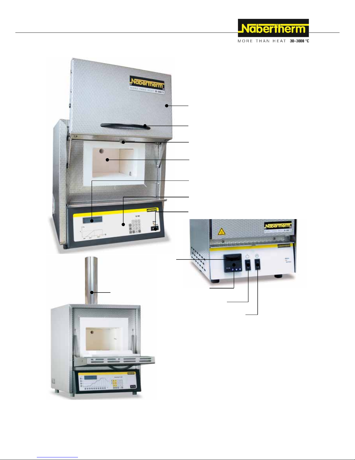
1.2 Overview of the Complete Furnace
Pos: 7 /TD/Einleitung/Lieferumfang/Öfen/Gesa mtübersicht Laborofen L-LE-L(T)-LV(T)-SKM-SW- HA @ 14\ mod_ 129 5003962965_51.docx @ 111859 @ @ 1
Furnace door
Handle
Furnace chamber
Air for the regulation of fresh air
Display
Controller
Power switch (ON/OFF)
Display
Controller
Power switch (ON/OFF)
Heating (ON/OFF)
Exhaust-air system
Page 8
8
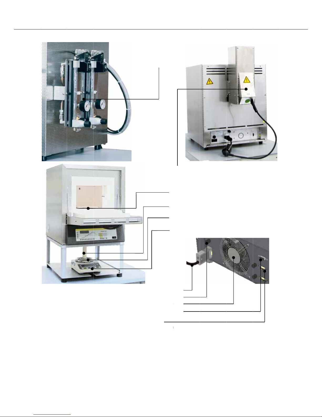
Fig. 1: Exa
m
Backup po
w
(lock for ba
c
for example
,
ple: Complet
e
er connectio
n
kup power c
o
for vent wit
h
e
overview o
f
D
nnection)
fan or gas s
u
various labo
r
Gas s
u
(addit
i
igital interfa
c
pply system
(
atory furnac
e
pply syste
m
i
onal equipm
e
V
(
Powe
r
Switchge
a
L
e RS 422 (op
additional eq
u
s
Scale
Ceramic die
Support plate
nt)
ent, vent wi
t
accessories)
Support die
line
r fan
ock
tion)
u
ipment)
in the furnac
e
h fan or catal
e
chamber
ytic converte
r
Page 9

9
Pos: 8 /TD/Einleitung/Produktbeschreibung/Öfen/ Überschrift - Absicherung von Gefahren bei Übertemper atur @ 37\mod_1362489730884_51.docx @ 213987 @ 2 @ 1
Safety control circuit
1.3 Safeguarding against Dangers Posed by Over-Temperature
Pos: 9 /TD/Einleitung/Produktbeschreibung/Öfen/S i cherheitseinrichtung - Überwachung der Ofenraumte mperatur (TWB-TWW) - Beschreibung @ 37\mod_1362491214270 _51.docx @ 214092 @ @ 1
Over-temperature limiters with manual reset/with automatic reset to protect against overtemperature in the furnace chamber are available for Nabertherm GmbH furnaces either as
a standard feature (depending on the model series) or as additional equipment (customized
design).
The over-temperature limiter with manual reset/with automatic reset monitors the furnace
chamber temperature. The display shows the most recently set cut-off temperature. If the
furnace chamber temperature rises about the pre-set cut-off temperature the heating is shut
down to protect the furnace, the charge and/or the operating equipment.
Pos: 10 /TD/Sicherheit/Sicherheitssymbole/W arnhinweise-ISO-ANSI/Warnsymbol_Gefahr - Absic herung von Gefahren bei Übertemperatur am TWB-TWW @ 37\mod_136249 0404 893_51.docx @ 214067 @ @ 1
DANGER
• Danger caused by incorrectly entered cut-off
temperature at the over-temperature limiter with
manual reset/over-temperature limiter with automatic
reset.
• Mortal danger
• If, as a result of over-temperature from the charge and/or the
operating equipment, a charge is likely to be damaged at this preset cut-off temperature of the over-temperature limiter with
manual reset/over-temperature limiter with automatic reset, or if
the charge itself becomes a source of danger for the furnace or its
surroundings, the cut-off temperature must be reduced at the
over-temperature limiter with manual reset/automatic reset to the
maximum permissible value.
Pos: 11 /TD/Betrieb_Bedienung/Vor Inbetriebnahme des Ofens ist die Bedienungsanleitung... (TWB-TWW) - Text @ 37\mod_1362494080225_51.docx @ 214142 @ @ 1
Read the operating instructions of the over-temperature limiter with manual reset/with
automatic reset before starting the furnace. The safety sticker must be removed from the
over-temperature limiter with manual reset/with automatic reset. Any time a change is
made in the heat treatment program, the maximum permissible cut-off temperature (alarm
trigger temperature) at the over-temperature limiter with manual reset/with automatic reset
must be checked or re-entered.
Pos: 12 /TD/Betrieb_Bedienung/die maximale Solltemper atur des Wärmeprogramms Controller zwischen 5 °C und 30 °C (TW B- TWW) @ 39\mod_1363784610371_51.docx @ 218500 @ @ 1
We recommend setting the maximum setpoint temperature of the heating program in the
limiter between 5 °C and 30 °C, depending on the physical characteristics of the furnace,
below the trigger temperature of the over-temperature limiter with manual reset/with
automatic reset. This prevents an unwanted triggering of the over-temperature limiter with
manual reset/with automatic reset.
Pos: 13 /TD/Betrieb_Bedienung/Aufkleber vom TWB/TWW abziehen - Grafik @ 37\mod_1362492020088_51.docx @ 214117 @ @ 1
Description and function, see the
Operating Instructions of the overtemperature limit controller/guard
Fig. 2: Removing the sticker
Page 10

10
Pos: 14 /TD/Einleitung/Produktbeschreibung/ Öfen/ Überschrift - Entschlüsselung der Modellbezeic hnung @ 2\ mod
_
1.3.1 Ke
Pos: 15 /TD/Einleitung/Produktbeschreibung/ Öfen/ Entschlüssellung der Modellbezeichnung Laborofen L- LE-L(T)-L
V
Example
LT 9/11SK
M
LT 9/11SK
M
LT 9/11SK
M
LT 9/11SK
M
Pos: 16 /TD/Einleitung/Lieferumfang/Öfen/Über sc hrift - Lieferumfang @ 0\mod_1167822508130_51.doc x @ 5112
@ _
1184245078907_51.docx @ 19775 @ 3 @ 1
y to the
M
V
(T)-SKM-SW-HA @ 14\mod_1299593606987_51.docx @ 113253 @ @ 1
@
2 @ 1
odel Na
m
Explanati
o
L = L
a
LE = L
a
LT = L
a
LV = L
a
LVT = L
a
1 = 1
-
2 = 2
-
3 = 3
-
4 = 4
-
5 = 5
-
6 = 6
-
9 = 9
-
14 = 14-l
i
15 = 15-l
i
24 = 24-l
i
40 = 40-l
i
11 = Tmax
12 = Tmax
13 = Tmax
HA =
L
SKM =
F
SW =
S
Fig. 3: Exa
m
es
n
boratory fur
n
boratory fur
n
boratory fur
n
boratory inci
n
boratory inci
n
liter furnace
c
liter furnace
c
liter furnace
c
liter furnace
c
liter furnace
c
liter furnace
c
liter furnace
c
i
ter furnace c
h
i
ter furnace c
h
i
ter furnace c
h
i
ter furnace c
h
1100 °C (20
1
1200 °C (21
9
1300 °C (23
7
aboratory f
u
urnace cha
m
cale furnace
ple: Model
d
ace with dro
p
ace econom
y
ace with lift
d
nerator with
d
nerator with l
c
hamber (vol
u
c
hamber (vol
u
c
hamber (vol
u
c
hamber (vol
u
c
hamber (vol
u
c
hamber (vol
u
c
hamber (vol
u
amber (volu
m
amber (volu
m
amber (volu
m
amber (volu
m
2 °F)
2 °F)
2 °F)
rnace with re
c
ber made of
c
with support
d
esignation (
t
-down door
series
oo
r
rop-down do
ift doo
r
me in L)
me in L)
me in L)
me in L)
me in L)
me in L)
me in L)
e in L)
e in L)
e in L)
e in L)
irculating ai
r
eramic muff
l
frame and sc
a
ype plate)
www.naberthe
r
LT 9/11S
K
LC011H6S
N
230 V 1/N/
P
fan in the ba
c
e
le
m.de
M
E~ 15.2 A
ck wall
Made
SN
x
1100 °C
50/60 Hz 3.5
k
in German
y
xxxxx
2011
W
Page 11

1.4 Sco
Pos: 17 /TD/Einleitung/Lieferumfang/Öfen/Liefer u mfang - Laborofen L-LE-L(T)-LV(T)-SKM-SW-HA @ 14\mod_129
9
Pos: 18 /TD/Betrieb_Bedienung/Die mitgelieferten Unt erlagen beinhalten nicht zwangsläufig elektrisc he Schaltplän
e
pe of Deli
9
662508331_51.docx @ 113310 @ @ 1
e
bzw. Pneuma ... @ 47\mod_1380028074616_51.docx @ 247668 @ @ 1
B
e
t
r
i
e
b
s
a
n
l
e
i
t
u
n
P
r
o
z
e
s
s
d
o
k
u
m
e
n
t
a
t
i
o
C
o
n
t
r
o
l
t
h
e
r
m
M
V
very
The scop
e
Furnace
Laborato
Power c
a
Vent ) 2)
Vent wit
h
Catalytic
Ceramic
Ceramic
Steel cat
c
Base Pla
t
Gas sup
p
Scale 2)
Process
d
Controlt
h
Other co
m
p
articula
r
Docume
n
Instructi
o
Operatin
g
Operatin
g
gas supp
l
Operatin
g
Controlt
h
Other do
c
p
articula
r
1) = in s
c
2) = in s
c
3) = qua
n
4) = qua
n
Caution
Make sure
t
tested duri
n
Note
The docu
m
schematics
.
If you nee
d
n
g
M
a
d
e
i
n
G
e
r
m
a
n
y
o
n
of deliver
y
components
r
y furnace 1)
ble 1)
fan 1) 2)
converter 1)
2
ribbed plate
ceramic catc
h
h basin
e 1)
ly system 2)
ocumentatio
n
erm MV sof
t
ponents, va
r
furnace
t type
n Manual La
b
Instructions
Instructions
y system 1)
Instructions
erm MV sof
t
uments, vari
a
furnace
ope of deliv
e
ope of deliv
e
tity depends
tity depends
t
hat all docu
m
g manufactu
r
ents included
the respectiv
includes:
2)
basin
ware packag
e
iable depend
i
b
oratory Fur
n
for Controll
e
ware packag
e
a
ble dependi
n
ry depends o
n
ry depend o
n
on furnace
m
on on need,
s
ents are care
f
ing and prior
do not alwa
y
e schematics
Q
111
431
1
1) 2)
1
ng on the
-
Q
ace 1)
1
r 1)
1
1
1)
1
g on the
-
design/furn
a
need, see shi
p
odel
ee shipping p
f
ully stored.
A
to shipping.
s contain the
e
t
hey can be o
r
uantity C
x
N
x
N
x
)
)
x
N
x
N
x
N
- - C
pa
uantity C
x
N
x
N
x
N
x
N
- -
ce model
ping papers
a
pers
ll the functi
o
lectrical sch
e
dered from
N
omment
abertherm G
m
abertherm G
m
abertherm G
m
abertherm G
m
abertherm G
m
onsult the shi
pers
omment
abertherm G
m
abertherm G
m
abertherm G
m
abertherm G
m
ns of this fur
n
matics and p
n
abertherm S
e
1
1
bH
bH
bH
bH
bH
p
ping
bH
bH
bH
bH
ace were
n
eumatic
rvice.
Page 12
12
Pos: 19 /TD/Einleitung/Technische Daten/Öfen/Über schrift - Technische Daten - mit Hinweis @ 0\mod_1167822840737_ 51.docx @ 5121 @ 1 @ 1
2 Specifications
Electrical specifications are on the type plate located on the side of the furnace.
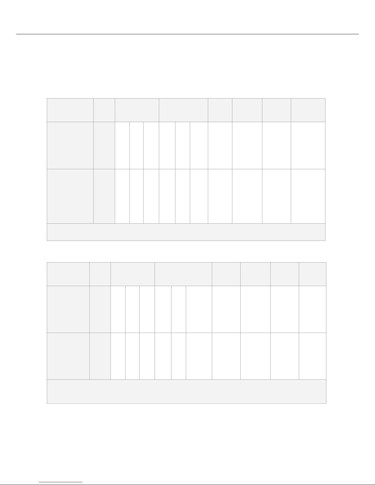
Pos: 20 /TD/Einleitung/Technische Daten/Öfen/Mode ll Muffelofen Klapptür -Tabelle für L 3/11 - L 40/11 bis L 1/12 - L 40/ 12 @ 14\mod_1294910652628_51.docx @ 111513 @ @ 1
Muffle Furnace
Model
Drop-Down Door
Tmax
°C
Dimensions
Interior in mm
w d h
Dimensions
Outer in mm
W D H
Volume
in l
Heating
power in
kW*
Weight
kg
Minutes
to
Tmax1
L 3/11 1100 160 140 100 380 370 420 3 1.2 20 60
L 5/11 1100 200 170 130 440 470 520 5 2.4 35 60
L 9/11 1100 230 240 170 480 550 570 9 3.0 45 75
L 15/11 1100 230 340 170 480 650 570 15 3.5 55 90
L 24/11 1100 280 340 250 560 660 650 24 4.5 75 95
L 40/11 1100 320 490 250 600 790 650 40 6.0 95 95
L 1/12 1200 90 115 110 250 265 340 1 1.5 10 25
L 3/12 1200 160 140 100 380 370 420 3 1.2 20 75
L 5/12 1200 200 170 130 440 470 520 5 2.4 35 75
L 9/12 1200 230 240 170 480 550 570 9 3.0 45 90
L 15/12 1200 230 340 170 480 650 570 15 3.5 55 105
L 24/12 1200 280 340 250 560 660 650 24 4.5 75 110
L 40/12 1200 320 490 250 600 790 650 40 6.0 95 110
1
for connection to 230 V 1/N/PE or 400 V 3/N/PE
*Depending on furnace design connected load might be higher
Pos: 21 /TD/Einleitung/Technische Daten/Öfen/Mode ll Muffelofen Hubtür -Tabelle für LT 3/11 - LT 40/11 bis LT 3/12 - LT 40/ 12 @ 14\ mod_1294933924209_51.docx @ 111553 @ @ 1
Muffle Furnace
Model
Lift Door
Tmax
°C
Dimensions
Interior in mm
w d h
Dimensions
Outer in mm
W D H+Ha2
Volume
in l
Heating
power in
kW*
Weight
kg
Minutes
to
Tmax1
LT 3/11 1100 160 140 100 380 370 420+165 3 1.2 20 60
LT 5/11 1100 200 170 130 440 470 520+220 5 2.4 35 60
LT 9/11 1100 230 240 170 480 550 570+290 9 3.0 45 75
LT 15/11 1100 230 340 170 480 650 570+290 15 3.5 55 90
LT 24/11 1100 280 340 250 560 660 650+335 24 4.5 75 95
LT 40/11 1100 320 490 250 600 790 650+335 40 6.0 95 95
LT 3/12 1200 160 140 100 380 370 420+165 3 1.2 20 75
LT 5/12 1200 200 170 130 440 470 520+220 5 2.4 35 75
LT 9/12 1200 230 240 170 480 550 570+290 9 3.0 45 90
LT 15/12 1200 230 340 170 480 650 570+290 15 3.5 55 105
LT 24/12 1200 280 340 250 560 660 650+335 24 4.5 75 110
LT 40/12 1200 320 490 250 600 790 650+335 40 6.0 95 110
1
for connection to 230 V 1/N/PE or 400 V 3/N/PE
2
incl. opened lift door
*Depending on furnace design connected load might be higher
Pos: 22 /TD/Einleitung/Technische Daten/Öfen/Mode ll Muffelofen Klapptür -Tabelle für L 5/13 - L 15/13 @ 14\mod_129499 1083275_51.docx @ 111629 @ @ 1
Page 13

13
Muffle Furnace
Model
Drop-Down Door
Tmax
°C
Dimensions
Interior in mm
w d h
Dimensions
Outer in mm
W D H
Volume
in l
Heating
power in
kW*
Weight
kg
Minutes
to
Tmax1
L 5/13 1300 200 170 130 440 470 520 5 2.4 45 45
L 9/13 1300 230 240 170 480 550 570 9 3.0 50 50
L 15/13 1300 230 340 170 480 650 570 15 3.5 60 60
1
for connection to 230 V 1/N/PE or 400 V 3/N/PE
*Depending on furnace design connected load might be higher
Pos: 23 /TD/Einleitung/Technische Daten/Öfen/Mode ll Muffelofen Hubtür -Tabelle für LT 5/13 - LT 15/13 @ 14\mod_12949 9104 0209_51.docx @ 111583 @ @ 1
Muffle Furnace
Model
Lift Door
Tmax
°C
Dimensions
Interior in mm
w d h
Dimensions
Outer in mm
W D H+Ha2
Volume
in l
Heating
power in
kW*
Weight
kg
Minutes
to
Tmax1
LT 5/13 1300 200 170 130 440 470 520+220 5 2.4 42 45
LT 9/13 1300 230 240 170 480 550 570+290 9 3.0 60 50
LT 15/13 1300 230 340 170 480 650 570+290 15 3.5 70 60
1
for connection to 230 V 1/N/PE or 400 V 3/N/PE
2
incl. opened lift door
*Depending on furnace design connected load might be higher
Pos: 24 /TD/Einleitung/Technische Daten/Öfen/Mode ll Kompakt-Muffelofen Klapptür -Tabelle für LE 1/11 - LE 14/11 @ 14\mod_1294992044264_51.docx @ 111652 @ @ 1
Compact Muffle Furnace
Model
Drop-Down Door
Tmax
°C
Dimensions
Interior in mm
w d h
Dimensions
Outer in mm
W D H
Volume
in l
Heating
power in
kW*
Weight
kg
Minutes
to
Tmax1
LE 1/11 1100 90 115 110 250 265 340 1 1.5 10 10
LE 2/11 1100 110 180 110 275 380 350 2 1.8 10 25
LE 4/11 1100 170 200 170 335 400 410 4 1.8 15 35
LE 6/11 1100 170 200 170 510 400 320 6 1.8 18 35
LE 14/11 1100 220 300 220 555 500 370 14 2.9 25 40
1
for connection to 230 V 1/N/PE or 400 V 3/N/PE
*Depending on furnace design connected load might be higher
Pos: 25 /TD/Einleitung/Technische Daten/Öfen/Mode ll Veraschungsofen Klapptür -Tabelle für LV 3/11 - LV 15/ 11 @ 14\ mod_1294992766140_51.docx @ 111675 @ @ 1
Incinerator
Model
Drop-Down Door
Tmax
°C
Dimensions
Interior in mm
w d h
Dimensions
Outer in mm
W D Hb2
Volume
in l
Heating
power in
kW*
Weight
kg
Minutes
to
Tmax1
LV 3/11 1100 160 140 100 380 370 750 3 1.2 20 120
LV 5/11 1100 200 170 130 440 470 850 5 2.4 35 120
LV 9/11 1100 230 240 170 480 550 900 9 3.0 45 120
LV 15/11 1100 230 340 170 480 650 900 15 3.5 55 120
1
for connection to 230 V 1/N/PE or 400 V 3/N/PE
2
incl. exhaust air pipe (Ø 80 mm)
*Depending on furnace design connected load might be higher
Page 14

14
Pos: 26 /TD/Einleitung/Technische Daten/Öfen/Mode ll Veraschungsofen Hubtür -Tabelle für LVT 3/11 - LVT 15/11 @ 14\mod_1 294992895007_51.docx @ 111698 @ @ 1
Incinerator
Model
Lift Door
Tmax
°C
Dimensions
Interior in mm
w d h
Dimensions
Outer in mm
W D Hb2
Volume
in l
Heating
power in
kW*
Weight
kg
Minutes
to
Tmax1
LVT 3/11 1100 160 140 100 380 370 750 3 1.2 20 120
LVT 5/11 1100 200 170 130 440 470 850 5 2.4 35 120
LVT 9/11 1100 230 240 170 480 550 900 9 3.0 45 120
LVT 15/11 1100 230 340 170 480 650 900 15 3.5 55 120
1
for connection to 230 V 1/N/PE or 400 V 3/N/PE
2
incl. exhaust air pipe (Ø 80 mm)
*Depending on furnace design connected load might be higher
Pos: 27 /TD/Einleitung/Technische Daten/Öfen/Mode ll Muffelofen mit Keramikmuffel Klapptür/Hubtür - Tabelle für L 9/11/SKM - LT 9/11/SKM @ 14\mod_1294994910658_51.doc x @ 111721 @ @ 1
Muffle Furnace
Model
Drop-Down
Door/
Lift Door
Tma
x
°C
Dimensions
Interior in mm
w d h
Dimensions
Outer in mm
W D H+Ha2
Volume
in l
Heating
power in
kW*
Weight
kg
Minutes
to
Tmax1
L 9/11/SKM 1100 230 240 170 480 550 570 9 3.0 50 90
LT 9/11/SKM 1100 230 240 170 480 550 570+290 9 3.0 50 90
1
for connection to 230 V 1/N/PE or 400 V 3/N/PE
2
incl. opened lift door
*Depending on furnace design connected load might be higher
Pos: 28 /TD/Einleitung/Technische Daten/Öfen/Mode ll Muffelofen mit Klapptür und Waage -Tabelle für L 9/11/SW - L 9/ 12/SW @ 14\mod_1294995752712_51.docx @ 111744 @ @ 1
Muffle Furnace
Model
Drop-Down
Door
Tmax
°C
Dimensions
Interior in mm
w d h
Dimensions
Outer in mm
W D H
Volume
in l
Heating
power in
kW*
Weight
kg
Minutes
to
Tmax1
L 9/11/SW 1100 230 240 170 480 550 800 9 3.0 55 75
L 9/12/SW 1200 230 240 170 480 550 800 9 3.0 55 90
1
for connection to 230 V 1/N/PE or 400 V 3/N/PE
*Depending on furnace design connected load might be higher
Pos: 29 /TD/Einleitung/Technische Daten/Öfen/Mode ll Muffelofen mit Hubtür und Waage -Tabelle für LT 9/11/SW - LT 9/12/ SW @ 14\mod_1294996314888_51.docx @ 111767 @ @ 1
Muffle Furnace
Model
Drop-Down
Door
Tmax
°C
Dimensions
Interior in mm
w d h
Dimensions
Outer in mm
W D H+Ha2
Volume
in l
Heating
power in
kW*
Weight
kg
Minutes
to
Tmax1
LT 9/11/SW 1100 230 240 170 480 550 800+290 9 3.0 55 75
LT 9/12/SW 1200 230 240 170 480 550 800+290 9 3.0 55 90
1
for connection to 230 V 1/N/PE or 400 V 3/N/PE
2
incl. opened lift door
*Depending on furnace design connected load might be higher
Pos: 30 /TD/Einleitung/Technische Daten/Öfen/Mode ll Waage für Muffelofen L/LT 9/11-12/SW -Tabelle für EW- 2200/4200/6200/12000 @ 14\mod_1294996701851_51.docx @ 111790 @ @ 1
Page 15
15
Scale
Type Readability
in g
Weight Range
in g
Stamp Weight
in g
Calibration Value
in g
Minimum Load
in g
EW-2200 0.01 2200 incl. plunger 850 0.1 0.5
EW-4200 0.01 4200 incl. plunger 850 0.1 0.5
EW-6200 0.01 6200 incl. plunger 850 - 1.0
EW-12000 0.10 12000 incl. plunger 850 1.0 5.0
Pos: 31 /TD/Einleitung/Technische Daten/Öfen/Mode ll Muffelofen Hubtür -Tabelle für LT 5/11HA - LT 15/11HA @ 14\mod_1294 997879629_51.docx @ 111813 @ @ 1
Muffle Furnace
Model
Lift Door
Tmax
°C
Dimensions
Interior in mm
w d h
Dimensions
Outer in mm
W D H+Ha2
Volume
in l
Heating
power in
kW*
Weight
kg
Minutes
to
Tmax1
LT 5/11HA 1100 200 160 130 440 470 520+220 5 2.4 36 60
LT 9/11HA 1100 230 230 170 480 550 570+290 9 3.0 46 60
LT 15/11HA 1100 230 330 170 480 650 570+290 15 3.5 56 75
1
for connection to 230 V 1/N/PE or 400 V 3/N/PE
2
incl. opened lift door
*Depending on furnace design connected load might be higher
Pos: 32 /TD/Einleitung/Technische Daten/Öfen/Mode ll-Tabelle für Laboröfen L-LE-L(T)-LV(T)-SKM-SW -HA - Grafik - 1 @ 14\mod_1300087573327_51.docx @ 113363 @ @ 1
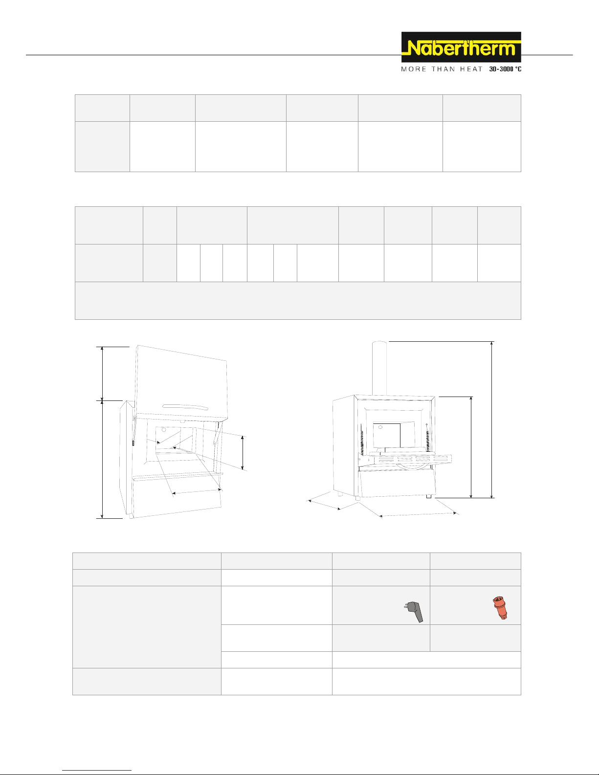
Fig. 4: Dimensions
Pos: 33 /TD/Einleitung/Technische Daten/Öfen/Tabe lle für Laboröfen L/LT/LE/LV/LVT/ - Öfen - 1 @ 14\mod_12950010508 44_51.docx @ 111836 @ @ 1
Electrical connection
1-phase: (1 N/PE) 3-phase: (3 N/PE)
Model:
to 3.6 kW from 4.5 kW
Power plug
Protective contact plug
(with snap-in socket)
CEE plug
Voltage:
110 V – 240 V
220 V – 240 V
380 V – 480 V
Frequency: 50 or 60 Hz
Heating output in kW: see section "Specifications" or type plate on the
furnace
w
d
D
h
Hb
H
Ha
W
H
Page 16

16
Thermal protection class
Furnaces:
as specified in DIN EN 60519-2
without safety controller Class 0
Protective type
Furnaces: IP20
Ambient conditions for electrical
equipment
Temperature: Humidity: +5 °C to + 40 °C max. 80 % not
condensing
Pos: 34 /TD/Einleitung/Technische Daten/Öfen/Tabe lle Dauerschalldruckpegel < 80 dB(A) - 2 @ 1\mod_1170750985488_ 51.docx @ 8913 @ @ 1
Emissions
Continuous sound pressure
level:
< 80 dB(A)
Pos: 35 /TD/Einleitung/Gewährleistung_Haftung/ Überschrift - Gewährleistung und Haftung 1.1 @ 0\mod_116782 2979492_51.docx @ 5130 @ 2 @ 1
2.1 Warranty and Liability
Pos: 36 /TD/Einleitung/Gewährleistung_Haftung/ Öfe n und Schaltanlagen - Gewährleistung und Haftung @ 0\mod_1157 536440972_51.docx @ 1569 @ @ 1
§
As regards warranty and liability, the normal Nabertherm warranty terms apply,
unless individual terms and conditions have been agreed. However, the following
conditions also apply:
Warranty and liability claims for personal injury or damage to property shall be excluded if
they are attributable to one or more of the following causes:
Everyone involved in operation, installation, maintenance, or repair of the furnace
must have read and understood the operating instructions. No liability will be accepted
for damage or disruptions to operation resulting from non-compliance with the
operating instructions.
Not using the furnace as intended,
Improper installation, start-up, operation, or maintenance of the furnace,
Operation of the furnace with defective safety equipment or improperly installed or
non-functioning safety and protective equipment,
Not observing the references in the operating instructions to transportation, storage,
installation, start-up, operation, maintenance, or equipping the furnace,
Making unauthorized changes to the furnace,
Making unauthorized changes to the operating parameters,
Making unauthorized changes to the parameterization, the settings, or the program,
Original parts and accessories are designed especially for Nabertherm furnaces.
Replace parts only with original Nabertherm parts. Otherwise the warranty will be
void. Nabertherm accepts absolutely no liability for damage caused by using parts that
are not original Nabertherm parts.
Catastrophes due to third-party causes and force majeure.
Page 17
17
Pos: 37 /TD/Sicherheit/Überschrift - Sicherhei t @ 0\mod_1158843961540_51.docx @ 3103 @ 1 @ 1
3 Safety
Pos: 38 /TD/Sicherheit/Überschrift - Bestimmungsge mäße Verwendung @ 0\mod_1167823503921_51.docx @ 5148 @ 2 @ 1
3.1 Intended Use
Pos: 39 /TD/Sicherheit/Bestimmungsgemäße Verwendung L HT-Hochtemperaturöfen (Tischmodell) @ 2\mod_1182347443 948_51.docx @ 18724 @ @ 1
Safety
This Nabertherm system was designed and manufactured after careful selection of the
harmonized standards to be observed as well as other technical specifications. It therefore
corresponds to the state of the art, ensuring the highest possible degree of safety.
Only materials with known characteristics and melting temperatures may be used. Check
the material safety data sheets if necessary.
Use of the furnace for any other purpose whatsoever such as processing
products other than those intended or handling hazardous substances or
substances posing a health hazard constitutes improper use and must be
agreed upon with Nabertherm in writing.
Whether or not the materials used in the furnace can potentially corrode or destroy
the insulation or heating elements must be ascertained.
For furnaces with over-temperature limiters, the cutoff temperature must be set to prevent
overheating of the material.
Modifications to system equipment must be agreed upon with
Nabertherm in writing. It is not permitted to remove, bypass, or shut down safety devices.
The installation instructions and safety guidelines must be observed. Otherwise, the furnace
will not be considered as being used as designated, and all claims against Nabertherm
GmbH will be void.
Opening the furnace when hot (temperature greater than 200/392 °C/°F) can lead to
accelerated wear of the following components: insulation, heating elements, and furnace
housing.
Operating with power sources, products, operating equipment, additives,
etc. that are subject to the Ordinance on Hazardous Substances or cause
risks to the health of operating personnel in any way is not permitted.
- This furnace is designed for commercial use. The furnace must not be used
for heating food, animals, wood, grain, etc.
- The furnace must not be used as a workplace heater.
- Do not use the furnace to melt ice or similar materials.
- Do not use the furnace as a clothes dryer.
Note
See safety instructions in the individual sections.
Page 18
18
Pos: 40 /TD/Allgemeine Hinweise (für alle Anleitungen)/ Hinweis - Dieser Ofen verfügt über keine Sicherheitstechni
k
Pos: 41 /TD/Allgemeine Hinweise (für alle Anleitungen)/ Hinweis - Dieses Produkt entspricht nicht der ATEX-Ric htli
n
Pos: 42 /TD/Sicherheit/Überschrift - Anforder ungen an den Betreiber der Anlage @ 0\mod_1167823775531_51.do
c
3.2 Req
Pos: 43 /TD/Sicherheit/Anforderungen an den Betreiber der Anlage - RHTH, RHTC, LHT, Rohröfen @ 2\mod_1184
k
für Prozesse, ..-nicht brennbare Gase @ 8\mod_12350 3869 9771_51.docx @ 51483 @ @ 1
n
ie und darf nicht ..-nicht brennbare Gase @ 2\mod_1184228 756893_51.docx @ 19686 @ @ 1
c
x @ 5157 @ 2 @ 1
uirement
s
4
570280797_51.docx @ 19913 @ @ 1
Caution
Operating
t
mixtures c
r
This furna
c
mixtures,
fo
If the furn
a
gas mixtur
e
pre-requisi
t
situations
s
You must
e
N
aberther
m
involving t
h
Note
This produ
c
atmospher
e
where expl
o
for the
F
The set-up
b
e deemed
N
aberther
m
This level
o
measures h
measures a
n
The oper
a
al
l
sy
th
e
th
e
th
e
th
e
th
eop
th
e
th
ewi
al
lDa
fu
rsafins
a
rOcwo
al
lass
he furnace w
i
eated as a res
e features no
r example d
e
ce is still use
d
s in the furn
a
e applies not
uch as p
r
oce
s
nsure that th
e
offers a bro
a
e use of co
m
t does not c
o
s. It must not
sive gases o
r
urnace O
instructions a
n
to have been
u
GmbH.
f safety whe
n
a
ve been tak
e
d controllin
g
tor must e
n
harmful gas
e
s
tem,
extraction s
y
workplace i
s
furnace is o
p
functions of
required pe
r
erating, main
t
se operating
furnace. Th
e
th or on the f
u
the safety an
maged or un
r
nace person
n
ety and envi
r
tructions, es
p
isk assessme
n
cupational S
a
rking condit
i
other instruc
t
essment for
t
th explosive
g
ult of heating
safety techn
o
binding.
for such pr
o
ce must neve
only to norm
a
s disruptions
furnace is a
d
d range of f
u
bustible gas
m
mply with th
e
be operated
w
mixtures ar
e
perator
nd safety reg
u
used improp
e
operating th
e
n. It depends
how they ar
e
sure that
s are remove
d
stem is swit
c
properly ve
n
erated only i
n
the safety co
m
sonal protect
i
tenance, and
r
instructions,
i
se instructio
n
rnace;
d operating i
n
eadable sign
s
el are inform
e
onmental pr
o
ecially those
t is carried o
u
fety Act) to
d
ons particula
r
tions and saf
e
he workplac
e
ases or mixt
u
/drying, is pr
o
logy for proc
cesses despit
e
r exceed 3%
o
l operation
b
(caused, for
e
equately ven
t
rnaces which
ixtures.
ATEX Dire
c
ith explosiv
e
produced.
lations must
rly, effective
l
e
furnace can
on the furnac
carried out.
from the w
o
hed on,
tilated,
n
a perfect o
p
ponents are
ve equipmen
t
epair person
n
ncluding the
s must be av
a
struction sig
n
must be repl
d regularly
a
tection and a
r
involving sa
f
t (in Germa
n
etermine an
y
to the furna
c
ty guidelines
are compile
d
res, includin
g
hibited.
e
sses which
p
this fact, the
f the lower e
x
u
t, in particul
xample, by t
h
ilated and ve
n
were especia
l
tive and ma
y
gases or mi
x
b
e followed,
o
y cancelling
a
be achieved
o
operator's d
i
rkplace, for
e
erating condi
t
checked reg
u
is available
f
el.
upplier docu
m
ilable at all
t
i
s on the furn
a
a
ced immedi
a
b
out all issue
s
e familiar wi
t
ty,
y, covered b
y
other hazard
s
e's location,
that have bee
n
in an operati
g
explosive g
a
roduce comb
u
concentratio
n
x
plosion limi
t
ar, to excepti
o
e failure of a
n
ted.
l
ly developed
not
b
e used
i
tures or duri
n
therwise the
ny claims ag
a
nly if all the
i
ligence in pl
a
xample by a
n
t
ion and, in p
a
larly.
or and used
b
mentation, ar
e
mes for anyo
ce can be re
a
tely,
s involving o
c
h all the ope
r
Section 5 of
s that may re
s
n determined
on manual (i
n
ses or
stible
of organic
(LEL). This
nal
power unit).
for processe
s
n ignitable
g processes
furnace will
inst
n
ecessary
nning these
extraction
rticular, that
y the
kept near
n
e working
d properly.
cupational
ating
the
ult from the
in a risk
Germany,
Page 19

Pos: 44 /TD/Allgemeine Hinweise (für alle Anleitungen)/ Hinweis - In Deutschland ist die allgemeine Unfallverhü tung
a
Pos: 45 /TD/Sicherheit/Überschrift - Anforder ungen an das Bedienpersonal @ 0\mod_1167825643423_51.docx @
3.3 Req
Pos: 46 /TD/Sicherheit/Anforderungen an das Bedienpers onal @ 0\mod_1158218663482_51.docx @ 2155 @ @
1
g
svorschriften VBG bzw. BGZ zu beachten. @ 3\mod_1193667801 739_ 51.docx @ 26122 @ @ 1
5166 @ 2 @ 1
uirement
s
1
co
E
q
O
nrepantraad
peadev
Note
In German
y
The nation
a
for the
O
Everyone i
n
have read
a
damage or
d
instruction
s
Only adeq
u
furnace.
Operating
p
environme
n
safety instr
u
Only train
e
The oper
a
Oper
a
__
The f
u
__
The f
u
__
The f
u
__
Initia
l
__
Malf
u
__
The f
u
__
The f
u
__
The f
u
__
The f
u
__
The f
u
__
vered by Sec
t
uipment).
ly sufficientl
y
air the syste
m
d must confir
m
ining progra
m
ditional train
i
rformed by a
u
ditional train
i
idenced by t
h
, the general
l accident pr
e
perating
volved in op
nd understoo
d
d
isruptions to
.
ately qualifie
ersonnel are
tal protectio
n
ctions.
d personnel
m
tor should
tor
__________
_
rnace may o
n
__________
_
rnace may o
n
__________
_
rnace may o
n
__________
_
instructions
m
__________
_
nctions may
o
__________
_
rnace may o
n
__________
_
rnace may o
n
__________
_
rnace may o
n
__________
_
rnace may o
n
__________
_
rnace may o
n
__________
_
ion 6 of the
O
y qualified a
n
. This perso
n
their partic
must be do
c
ng must also
thorized, tra
i
ng must be p
a
e names and
s
accident prot
e
vention regu
l
Personn
e
eration, insta
l
the operati
n
operation re
s
d and authori
z
instructed re
g
and are fam
i
ay operate t
h
complete t
h
__________
_
ly be transp
o
__________
_
ly be install
e
__________
_
ly be commi
s
__________
_
ay only be
g
__________
_
nly be rectif
i
__________
_
ly be mainta
i
__________
_
ly be cleane
d
__________
_
ly be service
__________
_
ly be repaire
d
__________
_
ly be shut d
o
__________
_
rdinance Re
g
d authorized
p
nel must be
t
ipation in the
umented in
d
take place. T
h
ned individu
a
instakingly
d
ignatures of
t
ction guideli
ations of the
l
lation, maint
e
g instruction
s
ulting from
n
ed persons
m
ularly in all
a
liar with all t
h
e control and
ese detail
s
__________
_
rted by
__________
_
d by
__________
_
sioned by
__________
_
iven by
__________
_
ed by
__________
_
ned by
__________
_
by
__________
_
d by
__________
_
by
__________
_
wn by
__________
_
ulating the U
p
ersonnel ma
y
rained in ho
w
training with
etail. In case
a
e additional
t
ls familiar w
i
ocumented a
n
he participati
n
n
es of VBG
o
c
ountry of op
nance, or rep
.
N
o liability
w
on-complian
c
ay operate,
m
spects of occ
u
e operating i
n
safety equip
m
:
_
_________
_
_
_________
_
_
_________
_
_
_________
_
_
_________
_
_
_________
_
_
_________
_
_
_________
_
_
_________
_
_
_________
_
_
_________
_
se of Operati
n
y
operate, m
a
to operate t
h
a personal si
g
a
n operator is
raining may
o
th the syste
m
d participati
o
ng employee
s
r BGZ must
b
eration apply
.
air of the fur
n
will be accep
t
e with the op
aintain, or r
e
pational saf
e
nstructions, i
n
ent.
__________
_
__________
_
__________
_
__________
_
__________
_
__________
_
__________
_
__________
_
__________
_
__________
_
__________
_
1
9
g
intain and
e furnace
nature. The
replaced,
nly be
. The
n must be
.
e observed.
ace must
ed for
erating
pair the
ty and
particular,
_______
_______
_______
_______
_______
_______
_______
_______
_______
_______
_______
Page 20

20
Pos: 47 /TD/Sicherheit/Sicherheitssymbole/W arnhinweise-ISO-ANSI/Warnsymbol_Gefahr - Absic herung von Gefahren bei Übertemperatur am TWB-TWW @ 37\mod_136249 0404 893_51.docx @ 214067 @ @ 1
DANGER
• Danger caused by incorrectly entered cut-off
temperature at the over-temperature limiter with
manual reset/over-temperature limiter with automatic
reset.
• Mortal danger
• If, as a result of over-temperature from the charge and/or the
operating equipment, a charge is likely to be damaged at this preset cut-off temperature of the over-temperature limiter with
manual reset/over-temperature limiter with automatic reset, or if
the charge itself becomes a source of danger for the furnace or its
surroundings, the cut-off temperature must be reduced at the
over-temperature limiter with manual reset/automatic reset to the
maximum permissible value.
Pos: 48 /TD/Sicherheit/Überschrift - Schutzkleidu ng @ 0\mod_1167825795750_51.docx @ 5175 @ 2 @ 1
3.4 Protective Clothing
Pos: 49 /TD/Sicherheit/Schutzkleidung - Schutzkleid ung tragen @ 5\mod_1220274995030_51.docx @ 42108 @ @ 1
Wear protective clothing
Pos: 50 /TD/Sicherheit/Schutzkleidung - Hitzebeständi g e Handschuhe tragen @ 9\mod_1246542013306_51.doc x @ 62473 @ @ 1
Wear heat-resistant gloves to protect your hands.
Pos: 51 /TD/Sicherheit/Schutzkleidung - Schutzbril le tragen @ 5\mod_1220273954830_51.docx @ 42086 @ @ 1
Wear protective goggles.
Pos: 52 /TD/Sicherheit/Überschrift - Grundlegende Maß nah men bei Normalbetrieb @ 0\mod_1167825919827_51.doc x @ 5184 @ 2 @ 1
3.5 Basic Measures During Normal Operation
Pos: 53 /TD/Sicherheit/Grundlegende Maßnahmen bei Normal betrieb (LHT ../..-Tischmodell) (2012-11-07 14:33:12) @ 3\mod_1195478872113_51.docx @ 27827 @ @ 1
Risks during Normal Operation!
Before switching the furnace on, check and ensure that only authorized persons are in the
working area of the furnace and that no one can be injured as a result of operating the
furnace.
Before starting production each time, check and ensure that all the safety equipment works
properly.
Before starting production each time, check the furnace for obvious damage and ensure that
it is operated only in a perfect condition. Report any defects to a supervisor immediately.
Before starting production each time, remove all materials and objects that are not needed
for production from the working area.
At least once every day (see also Servicing and Maintenance) check the following:
Check the furnace for obvious external damage,
Page 21

21
Check that all safety equipment is working as intended (e.g. emergency stop button),
Check all hydraulic or pneumatic hoses, make sure that they are not leaking and that
they are connected properly (if applicable),
Check all gas and oil lines, make sure that they are not leaking and that they are
connected properly (if applicable),
Check that the fan works properly (if applicable)
Pos: 54 /TD/Sicherheit/Überschrift - Grundlegende Maß nah men im Notfall @ 1\mod_1170943369267_51.docx @ 9093 @ 2 @ 1
3.6 Basic Measures in Case of Emergency
Pos: 55 /TD/Sicherheit/Überschrift - Verhalten im Notf al l @ 1\mod_1170949904855_51.docx @ 9123 @ 3 @ 1
3.6.1 What to do in an Emergency
Pos: 56 /TD/Allgemeine Hinweise (für alle Anleitungen)/ Hinweis - Das Stillsetzen im Notfall ist vorgesehen durc h Ziehen des Netzsteckers. @ 6\mod_1222062836860_51.doc x @ 42829 @ @ 1
Note
The power plug is to be pulled out to stop the furnace in case of an emergency.
Therefore, the power plug must be accessible at all times when the furnace is operating so
that it can be pulled out quickly in case of an emergency.
Pos: 57 /TD/Sicherheit/Grundlegende Maßnahmen im Notfa ll - Netzstecker ziehen (alle Anleitungen) - Grafik @ 36\ mod_1360079722854_51.docx @ 208920 @ @ 1
Fig. 5: Pull the power plug (similar to picture)
Pos: 58 /TD/Allgemeine Hinweise (für alle Anleitungen)/ Warnung - Bei unerwarteten Vorgängen im Ofen (z.B. starke Rauc hent wicklung oder Geruchsbelästigung) @ 4\mod_120530657973 7_51.docx @ 34218 @ @ 1
Risks during Normal Operation!
Switch the furnace off immediately in case of unexpected occurrences in the furnace (e.g. a
lot of smoke or unusual smells). Wait until the furnace has cooled naturally to room
temperature.
Pos: 59 /TD/Sicherheit/Sicherheitssymbole/W arnhinweise-ISO-ANSI/Warnsymbol_Gefahr - Elektri sc her Schlag - Piktogramm elektr. Schlag - Hauptschalter @ 9\ mod_1247472185096_51.docx @ 63063 @ @ 1
DANGER
• Danger of electric shock.
• Risk of fatal injury.
• Work on electrical
equipment may be carried out only by
qualified electricians
or by trained personnel authorized by
Nabertherm.
• Before starting work, pull out the
power plug
Page 22

22
Pos: 60 /TD/Sicherheit/Überschrift - Grundlegende Maß nah men bei Wartung und Instandhaltung @ 0\mod_116782
3.7 Bas
Pos: 61 /TD/Sicherheit/Grundlegende Maßnahmen bei War tung und Instandhaltung @ 0\mod_1158222458436_51
.
Pos: 62 /TD/Sicherheit/Überschrift - Umweltschutzvor schriften @ 0\mod_1167826189237_51.docx @ 5202 @ 2 @
3.8 Env
Pos: 63 /TD/Sicherheit/Umweltschutzvorschri ften Schmierfette-Hydrauliköl-Kühlmittel @ 0\mod_11 58223424304_5
1
Pos: 64 /TD/Sicherheit/Umweltschutzvorschri ften Elektronische Bauteile-Isolierung-Altmetal l @ 4\mod_120514331
4
2
6060620_51.docx @ 5193 @ 2 @ 1
ic Measu
r
.docx @ 2188 @ @ 1
1
ironment
a
1.docx @ 2199 @ @ 1
4
853_51.docx @ 32563 @ @ 1
es for Se
r
Maintenan
c
instruction
s
and repair
w
may cause
i
Switch off
t
main switc
h
Clear an a
d
Suspended
risk of fata
l
Relieve th
e
work (if ap
p
When clea
n
them with
w
When mai
n
ensure the
f
Chec
k
Reins
t
Remo
work
f
Remo
Chec
k
Power
l Regula
t
All statuto
r
observed
w
Problem m
a
p
laced in n
o
During ins
t
such as
lubric
hydra
u
refrig
e
solve
n
sewa
g
These subs
t
containers.
Note
The operat
o
When it is
d
classificati
o
furnace ins
u
environme
n
vicing a
n
e work must
and the acci
d
ork be carri
e
i
njuries, deat
h
t
he furnace a
n
and secure i
equate area a
r
loads are dan
g
injury.
pressure on
h
p
licable).
ing furnaces,
ater.
tenance or re
p
ollowing:
that loosene
d
all protectiv
e
ve all materi
a
rom the wor
k
ve any liquid
s
that all safet
y
cables may b
e
ions
y duties rega
r
hen work is
c
terials that a
r
rmal waste
d
allation, repa
i
a
ting grease
a
lic oils
rants
-based clea
n
e system.
ances must b
r must ensur
e
elivered, thi
s
n necessary.
lation durin
g
t.
d Mainte
n
be performe
d
ent preventi
o
d out by the
s
, or consider
a
d make sure
i
t with a padl
o
ound the fur
n
gerous. Wor
k
ydraulic equ
i
control cabi
n
p
air work has
screw conn
e
equipment,
s
l, tools, and
o
ing area of t
h
that have le
a
y
functions (
e
e replaced on
l
ding waste a
v
arried out on
e no longer
n
isposal syste
m
r, and maint
e
nd oils
ing fluids m
u
e stored, tran
s
that nationa
l
furnace con
t
However, res
operation. T
h
ance
by authorize
d
n regulations
ervice team
o
ble damage
t
i
t cannot be s
w
ck), or pull o
u
ace to facilit
a
ing beneath
a
pment befor
e
ets, or electri
been comple
t
ctions have
b
creens, and f
i
ther equipme
e furnace,
ked,
.g. emergenc
y
l
y with simil
a
oidance, pro
p
and with the
f
eeded, such
a
s or allowe
d
nance work,
s
st not be allo
w
ported, colle
c
environmen
t
ains no subst
a
idues of proc
e
h
ese may be
h
persons foll
o
. We recom
m
f Naberther
m
o property.
itched on a
g
t the power
p
te the repair
w
suspended l
o
carrying out
c
al equipmen
t
ed, before re
c
een re-tighte
n
lters,
n
t used for th
e
stop button)
r, approved c
a
er recycling,
urnace.
s lubricants o
r
to enter the
s
ubstances th
a
ed to conta
m
ted, and disp
o
al regulation
s
nces that ma
k
ss materials
m
azardous to
h
owing the m
a
end that the
m
GmbH. No
n
ain inadverte
n
lug.
w
ork.
ad is prohibi
t
maintenance
t housings, n
e
ommencing
p
ed,
e maintenanc
e
work proper
l
a
bles.
and disposal
r batteries, m
u
ewage syste
m
t are hazardo
u
inate the soi
l
osed of in sui
t
are observe
d
e a hazardo
u
ay accumul
a
ealth and/or
t
intenance
aintenance
-compliance
n
tly (lock the
ed. There is
a
o
r repair
ver spray
oduction
or repair
y,
must be
st not be
.
u
s to water,
or enter the
t
able
.
s waste
te in the
he
Page 23

23
Dismantle the electronic components and dispose of them as electric scrap.
Remove the insulation and dispose of it as hazardous waste (See Servicing, Cleaning,
and Maintenance with Ceramic Fiber Material)
Dispose of the housing as scrap metal.
Pos: 65 /TD/Sicherheit/Sicherheitssymbole/W arnhinweise-ISO-ANSI/Erläuterung ANSI Z535.6 @ 8\mod_124 3323558881_51.docx @ 57444 @ 2 @ 1
3.9 Explanation of the Symbols and Warnings
Note
In the following operating instructions, specific warnings are given to draw attention to
residual risks that cannot be avoided when the furnace is operating. These residual risks
include dangers for humans/products/ the furnace, and the environment.
The symbols used in the operating instructions are especially intended to draw attention to
safety information.
The symbols used cannot replace the text of the safety information. Therefore, always read
the entire text.
Graphic symbols correspond to ISO 3864. In accordance with the American National
Standard Institute (ANSI) Z535.6 the following warning information and words are used in
this document:
The general hazard symbol, in combination with the words CAUTION, WARNING and
DANGER warns about the risk of serious injury. Observe the following information to
prevent injury or death.
NOTICE
Refers to a hazard that could damage or destroy the equipment.
CAUTION
Refers to a hazard with a minor or medium risk of injury.
WARNING
Refers to a hazard that could cause death, serious or irreversible injury.
DANGER
Refers to a hazard that could directly cause death, serious or irreversible injury.
Structure of the Warning: All Warnings are Structured as Follows
WARNING
• Type and source of the danger
• Consequences of non-compliance
• Action to prevent danger
Hazard symbol
Indicates the risk of injury
Signal word
Classifies the danger
Graphical symbols (optional)
according to ISO 3864:
Consequences, measures, and
prohibitions
Reference texts:
• Type and source of the danger
• Possible consequences of noncompliance
• Measures/Prohibitions
Page 24

24
Pos: 66 /TD/Sicherheit/Sicherheitssymbole/W arnhinweise-ISO-ANSI/Überschrift - Hinweissymbole i n der Anleitung
Pos: 67 /TD/Sicherheit/Sicherheitssymbole/W arnhinweise-ISO-ANSI/Hinweis - Unter diesem Symbol erha lten Sie
A
Pos: 68 /TD/Sicherheit/Sicherheitssymbole/W arnhinweise-ISO-ANSI/Piktogramm in der Anleitung - Gebo t - Geb ot s
z
Pos: 69 /TD/Sicherheit/Sicherheitssymbole/W arnhinweise-ISO-ANSI/Piktogramm in der Anleitung - Gebo t - W ichtig
Pos: 70 /TD/Sicherheit/Sicherheitssymbole/W arnhinweise-ISO-ANSI/Piktogramm in der Anleitung - Gebo t - W ichtig
Pos: 71 /TD/Sicherheit/Sicherheitssymbole/W arnhinweise-ISO-ANSI/Piktogramm in der Anleitung - Gebo t - Ne tzs te
@ 9\mod_1247053429626_51.docx @ 62751 @ @ 1
A
nweisungshinweise und ... @ 9\mod_1247053932311_51.doc x @ 62785 @ @ 1
zeichen - Wichtige Gebote sind zu befolgen @ 9\mod_124705617 5982_51.docx @ 62853 @ @ 1
g
e Information für den Bediener @ 9\mod_1247053200729_51.doc x @ 627 17 @ @ 1
g
e Information für das Wartungspersonal @ 9\mod_12470532060 42_51.docx @ 62734 @ @ 1
e
cker ziehen @ 9\mod_1247055471526_51.docx @ 62836 @ @ 1
or
Informati
o
Note
Below this
s
Rule - Rul
e
This symbo
l
p
eople agai
n
Rule - Imp
This symbo
l
instructions
Rule - Imp
This symbo
l
maintenanc
e
Rule - Pull
This symbo
l
Graphic
a
accordi
n
Consequ
e
p
rohibiti
o
Hazard s
y
Indicates
t
•
•
•
n Symbol
s
ymbol you w
Sign
draws attent
i
st injury and
ortant Infor
m
draws the o
p
that must be
f
ortant Infor
m
draws the m
a
instructions
Out the Po
w
tells the ope
r
l symbols (o
g
to ISO 386
4
nces, measu
r
ns
mbol
he risk of inj
u
Type and s
o
Consequen
c
Action to pr
e
in the Inst
r
ill find instru
c
on to import
a
show what is
mation for
O
erator's atten
t
ollowed.
mation for
M
intenance pe
(service) that
wer Plug
ator to pull o
u
ptional)
4:
es, and
ry
DANGE
R
urce of the
d
es of non-co
m
vent dange
r
uctions:
tions and pa
r
nt rules that
m
to be done i
n
perators
ion to import
a
aintenanc
e
rsonnel's atte
n
must be follo
u
t the power
p
Refe
r
• Typ
e
• Pos
s
comp
l
• Me
a
anger
pliance
ticularly use
fu
ust be follo
w
certain situa
t
nt informati
o
Personne
l
tion to impo
r
w
ed.
lug.
ence texts:
and source
o
ible consequ
e
iance
sures/prohibi
t
Grap
h
(opti
o
3864:
Instru
S
C
l informatio
n
ed. Rule sig
n
ions.
n and operat
i
tant operatin
g
f the danger
nces of non-
ions
hical symbol
nal) accordi
n
ctions or pro
h
ignal word
lassifies the
d
.
s protect
ng
and
s
to ISO
ibitions
anger
Page 25

Pos: 72 /TD/Sicherheit/Sicherheitssymbole/W arnhinweise-ISO-ANSI/Piktogramm in der Anleitung - Gebo t - Anheb
e
Pos: 73 /TD/Sicherheit/Sicherheitssymbole/W arnhinweise-ISO-ANSI/Piktogramm in der Anleitung - W ar nung - Hei
ß
Pos: 74 /TD/Sicherheit/Sicherheitssymbole/W arnhinweise-ISO-ANSI/Piktogramm in der Anleitung - W ar nung - elek
t
Pos: 75 /TD/Sicherheit/Sicherheitssymbole/W arnhinweise-ISO-ANSI/Piktogramm in der Anleitung - W ar nung - Um
k
Pos: 76 /TD/Sicherheit/Sicherheitssymbole/W arnhinweise-ISO-ANSI/Piktogramm in der Anleitung - W ar nung - Sch
w
Pos: 77 /TD/Sicherheit/Sicherheitssymbole/W arnhinweise-ISO-ANSI/Piktogramm in der Anleitung - W ar nung - Heb
e
Pos: 78 /TD/Sicherheit/Sicherheitssymbole/W arnhinweise-ISO-ANSI/Piktogramm in der Anleitung - W ar nung - Um
w
Pos: 79 /TD/Sicherheit/Sicherheitssymbole/W arnhinweise-ISO-ANSI/Piktogramm in der Anleitung - W ar nung - Bra
n
Pos: 80 /TD/Sicherheit/Sicherheitssymbole/W arnhinweise-ISO-ANSI/Piktogramm in der Anleitung - W ar nung - Expl
o
Pos: 81 /TD/Sicherheit/Sicherheitssymbole/W arnhinweise-ISO-ANSI/Piktogramm in der Anleitung - Gefahr - nicht
m
e
n mit mehreren Personen @ 9\mod_1247063058002_51.docx @ 62938 @ @ 1
ß
e Oberfläche - Oberfläche nicht berühren @ 9\mod_1247054774780 _51.docx @ 62802 @ @ 1
t
rischer Schlag - zur Vermeidung Anweisung folgen @ 9\mod_ 124 7055093892_51.docx @ 62819 @ @ 1
k
ippen des Gerätes @ 9\mod_1247059198372_51.docx @ 62870 @ @ 1
w
ebende Lasten @ 9\mod_1251450500309_51.docx @ 65454 @ @ 1
e
n schwerer Lasten @ 9\mod_1247059891358_51.docx @ 62887 @ @ 1
w
eltgefährdung @ 9\mod_1247060443419_51.doc x @ 62904 @ @ 1
n
dgefahr @ 9\mod_1251445272822_51.docx @ 65437 @ @ 1
l
osionsgefährliche Stoffe @ 9\mod_1247061148859_51.d ocx @ 62921 @ @ 1
m
it Wasser überschütten @ 9\mod_1247826410886_51.doc x @ 63819 @ @ 1
Rule - Lift
This symbo
l
and moved
t
Warning -
This symbo
l
Warning -
This symbo
l
warnings ar
e
Warning –
This symbo
l
warnings ar
e
Warning –
This symbo
l
suspended l
o
Warning –
This symbo
l
can lead to i
Warning –
This symbo
l
is not heede
d
observed.
Warning -
This symbo
l
followed.
Warning –
These symb
o
Prohibite
d
This symbo
l
the objects.
A
only with S
e
draws the p
e
o its final de
s
Hot Surfac
e
warns the o
p
Danger of
E
warns the o
p
not heeded.
Risk of De
v
tells the ope
r
not heeded.
Suspende
d
warns the o
p
ad is strictly
Danger if
H
warns the o
p
n
jury.
Risk to the
warns the o
p
. The operat
o
Fire Dange
r
warns opera
t
Risk of Ex
p
o
ls warn the
o
- Importan
t
warns the o
p
A
high-press
u
everal Peo
p
rsonnel's atte
n
tination by s
e
, Do Not T
o
erator that th
e
lectric Sh
o
erator that th
e
ice Toppli
n
ator that ther
e
Load
erator of pot
e
forbidden. Ig
n
eavy Load
s
erator of the
p
Environm
e
erator of the
r
r must ensur
e
ors of the da
n
losive Sub
perator of ex
p
Informati
o
erator that w
a
re cleaning
d
le
tion to the f
a
veral people.
uch
surface is h
o
ck
re is a risk o
f
g Over
is a risk of t
h
ntial dangers
n
oring this c
a
Are Lifted
otential dan
g
nt
isk to the en
v
e
that nationa
l
ger of fire if
t
s
tances or
E
p
losive subst
a
n for Oper
a
ter or cleani
n
evice must al
s
ct that this d
e
t and should
n
an electric s
h
e device top
p
of suspended
n
lead to fata
l
ers of lifting
h
ironment if t
h
environmen
t
t
he following
xplosive
A
nces or an e
x
t
ors
g products m
u
o not be use
d
vice may onl
y
not be touch
e
ock if the fo
l
ling over if
t
loads. Work
i
injury.
heavy loads.
I
e following
i
al regulation
s
information
i
tmosphere
plosive atmo
s
ust NOT be
p
.
2
5
be lifted
d.
lowing
he following
ng below a
gnoring this
nformation
are
s not
phere
oured over
Page 26

26
Pos: 82 /TD/Sicherheit/Sicherheitssymbole/W arnhinweise-ISO-ANSI/Überschrift - Warnhinweissy mbole an der Anl
a
Pos: 83 /TD/Sicherheit/Sicherheitssymbole/W arnhinweise-ISO-ANSI/Piktogramm an der Anlage - Warnung - Gefah
Pos: 84 /TD/Sicherheit/Sicherheitssymbole/W arnhinweise-ISO-ANSI/Piktogramm an der Anlage - Warnung - Gefah
Pos: 85 /TD/Sicherheit/Überschrift - Allgemeine Gefahr en an der Anlage @ 0\mod_1168596796288_51.docx @ 60
1
3.10 Ge
n
Pos: 86 /TD/Sicherheit/Allgemeine Gefahren (Verbr ennung, Quetschen, Strom) - Rohröfen @ 2\mod_1184666023
0
Pos: 87 /TD/Allgemeine Hinweise (für alle Anleitungen)/ Warnung - Es dürfen keine Gegenstände auf den/der Ofen
/
a
ge @ 9\mod_1247053700273_51.docx @ 62768 @ @ 1
h
r vor heißer Oberfläche und Verbrennung @ 9\mod_124705295714 5_51.docx @ 62700 @ @ 1
h
ren durch elektrischen Strom @ 9\mod_1247052639824_51. docx @ 62683 @ @ 1
14 @ 2 @ 1
eral Risk
s
0
22_51.docx @ 19974 @ @ 1
n
/Schaltanlage abgelegt/abgestellt werden... @ 4\mod_1203924555465_5 1.docx @ 31568 @ @ 1
Warning
S
Warning -
You may n
o
and materia
l
Warning -
Warning, d
a
with the
Warning!
- Risk of b
u
- The door
- Risk of c
r
lifting ta
b
- The swit
c
dangerous
e
- Do not in
s
cooling slo
t
switchge
a
Warning!
N
o objects
m
or explosio
n
igns on th
e
Hot Surfac
e
t always real
i
s, and even li
Danger of
E
ngerous elec
t
Furnace
General H
a
rning on the
h
andle/grip c
a
ushing on m
o
le, etc.)
hgear cabinet
lectrical volt
ert any obje
c
t
s on the
r or furnace
(
General Ha
z
m
ay be place
d
hazard.
Furnace:
, Danger o
f
ze that surfac
quids are hot
.
lectric Sh
o
ric voltage
zards!
furnace hous
i
n become ve
ving parts (d
o
(if present)
a
ages.
ts into the op
e
if present). T
h
z
ards!
or set down
Burning –
es, such as fu
r
Do not touc
h
ck!
ng and on th
e
ry hot during
or hinge, rot
a
nd the termin
a
nings on the
is poses a ri
s
on the furna
c
Do Not Tou
c
nace compo
n
the surface.
tube
operation; w
e
ry tube drive
l boxes on t
h
furnace hous
i
k of electric
s
e or switchge
ch
ents, furnace
ar gloves.
,
e system con
t
ng, exhaust
a
hock.
ar. Doing so
c
walls, doors
t
ain
ir holes, or
reates a fire
Page 27

27
Pos: 88 /TD/Sicherheit/Sicherheitssymbole/W arnhinweise-ISO-ANSI/Warnsymbol_Gefahr - Absic herung von Gefahren bei Übertemperatur am TWB-TWW @ 37\mod_136249 0404 893_51.docx @ 214067 @ @ 1
DANGER
• Danger caused by incorrectly entered cut-off
temperature at the over-temperature limiter with
manual reset/over-temperature limiter with automatic
reset.
• Mortal danger
• If, as a result of over-temperature from the charge and/or the
operating equipment, a charge is likely to be damaged at this preset cut-off temperature of the over-temperature limiter with
manual reset/over-temperature limiter with automatic reset, or if
the charge itself becomes a source of danger for the furnace or its
surroundings, the cut-off temperature must be reduced at the
over-temperature limiter with manual reset/automatic reset to the
maximum permissible value.
Pos: 89 /TD/Transport_Montage_Inbetriebnahme/Er sti n betriebnahme/Überschrift - Transport, Montage und Er stinbetriebnahme @ 0\mod_1158844227416_51.doc x @ 3112 @ 1 @ 1
4 Transportation, Installation, and Commissioning
Pos: 90 /TD/Transport_Montage_Inbetriebnahme/Er sti n betriebnahme/Überschrift - Anlieferung @ 0\mod_1167 826534889_51.docx @ 5220 @ 2 @ 1
4.1 Delivery
Pos: 91 /TD/Transport_Montage_Inbetriebnahme/Er sti n betriebnahme/Anlieferung - (Hinweise allgemein) @ 0\ mod_1158233508887_51.docx @ 2223 @ @ 1
Check that Everything is Complete
Compare the delivered items with the delivery note and the purchase order documents.
Immediately notify the carrier and Nabertherm GmbH of any missing or damaged parts, as
complaints at a later date cannot be acknowledged.
Danger of Injury
When the furnace is being lifted, parts of the furnace or the furnace itself could topple over,
slip, or fall. Before the furnace is lifted, make sure no one is in the working area. Wear
safety footwear and a hard hat.
Safety Instructions
Forklifts must be operated only by authorized personnel. The operator bears sole
responsibility for safe operation and the load.
When the furnace is being lifted, make sure that the ends of the forks or the load do
not catch on neighboring goods. Use a crane to move tall parts, such as control
cabinets.
Use only lifting equipment with sufficient load-bearing capacity.
Lifting gear must be attached only to positions that have been designated for this
purpose.
Attachments, piping, or cable conduits must never be used to affix lifting gear.
Unpackaged parts should only be lifted with ropes or straps.
Attach transportation equipment only to positions intended for this purpose.
Lifting and securing equipment must conform to the provisions contained in accident
prevention regulations.
Consider the weight of the furnace when choosing lifting and securing equipment.
(see Specifications)
Stainless steel parts (including mounting elements) must always be kept separate from
unalloyed steel parts.
Do not remove corrosion protection until immediately prior to assembly.
Page 28

28
Pos: 92 /TD/Transport_Montage_Inbetriebnahme/Er sti n betriebnahme/Anlieferung von Öfen mit einem Hubwagen
@
Pos: 93 /TD/Sicherheit/Sicherheitssymbole/W arnhinweise-ISO-ANSI/Warnsymbol_Vorsicht - Rutsc hen/Kippen des
@
2\mod_1184672460200_51.docx @ 20000 @ @ 1
Gerätes - Piktogramm Kippen/Heben/Anheben @ 9\mod_124706 4081950_51.docx @ 62955 @ @ 1
Risks du
r
Suspended
risk of fata
l
Note
Safety and
Transport
a
Observe th
e
1. Our
Tra
n
prev
loca
top
p
leas
t
2. Pus
h
truc
k
Fig. 6: Pall
e
3. Lift
is b
e
nei
g
4. Ma
k
Pus
h
not
t
5. Car
e
Try
ing Normal
loads are dan
injury.
accident prev
tion with a
P
maximum p
furnaces are
d
sport the fur
n
ent any dam
a
t
ion. When tr
a
ling over, an
d
two persons
.
the pallet tr
u
is complete
t truck is pu
s
the furnace c
a
ing lifted, m
a
hboring goo
d
e sure that th
e
the furnace
c
ransport the
f
fully lower t
h
not to set it d
o
•
•
•
•
•
Operation!
gerous. Wor
k
ention guidel
i
allet Truc
k
ermitted cap
a
elivered ex
w
ace in its ori
g
ge. Remove
t
a
nsporting th
e
damage. Th
e
Do not stor
e
ck underneat
h
ly
b
eneath th
e
hed complet
e
refully and
p
ke sure that t
h
s.
e
furnace is b
a
arefully, slo
w
urnace on in
c
e furnace at
i
wn too abru
p
Device may
Damage to
t
Risk of inju
r
heavy loads.
Transport d
e
packaging.
Several peo
p
ing beneath
a
nes applicabl
city of the pa
l
orks on woo
d
inal packagi
n
he packaging
furnace, ma
k
furnace sho
u
the furnace
h
the transpo
r
frame. Pay
a
l
y
beneath t
h
ay attention t
o
h
e ends of th
e
lanced safel
y
ly and with
t
lines.
ts final positi
o
tly.
CAUTIO
N
slip or toppl
e
he device.
y
from lifting
vice only in
o
le must carry
suspended l
o
e for forklift
t
let truck.
en frames to
g and with s
u
only when th
e sure it is s
e
ld be transp
o
in damp roo
tation frame.
ttention to ne
e transportati
o
its center of
forks or the
l
; if not, attac
h
he pallet truc
k
n. Pay atten
t
over.
riginal
the device.
ad is prohibi
t
rucks must b
e
facilitate unl
o
itable equip
m
e furnace is i
n
cured agains
t
rted and inst
a
ms or outdo
o
Make sure th
a
ighboring go
o
on frame
gravity. Wh
e
oad do not c
a
securing eq
u
k
at its lowes
t
ion to neighb
ed. There is
a
followed.
ading.
ent to
its final
sliding,
lled by at
rs.
t the pallet
ds.
n the furnace
tch on
ipment.
position. Do
o
ring goods.
Page 29

Pos: 94 /TD/Transport_Montage_Inbetriebnahme/Er stinbetriebnahme/Legende für Packstücke z.B. zer brechlich @
4.2 Un
p
Pos: 96 /TD/Allgemeine Hinweise (für alle Anleitungen)/ Hinweis -
A
llgemeiner Hinweis zur Verpackung (z.B. Labor
ö
Pos: 97 /TD/Transport_Montage_Inbetriebnahme/Er sti n betriebnahme/Auspacken kleine Öfen mit Stülpkar ton - Tei
l
Wear p
r
1\mod_1173776713307_51.docx @ 10746 @ @ 1
acking
ö
fen) @ 3\mod_1192437185846_51.docx @ 23509 @ @ 1
l 1 @ 2\mod_1184739616497_51.docx @ 20026 @ @ 1
otective
gloves
Symbols:
The intern
a
(Internatio
n
Institute fo
r
Descripti
o
Fragile
This side u
p
Keep dry
Sling here
Note
The furnac
e
all packagi
n
transportat
i
At least tw
o
1. Che
c
2. Re
m
3. Sla
c
tional standa
r
al Organizat
i
Standardiza
t
n Symb
o
packaging p
g material (
a
on securing e
people are
n
k the transp
o
ove tensioni
n
ken screws a
n
d symbols fo
r
on for Stand
a
ion).
l Expla
n
This s
y
marke
d
throw
n
The fr
e
such a
w
not be
r
p
ackag
Produc
moistu
r
p
articu
l
halls o
r
tarpaul
i
The sy
m
not the
distanc
the pa
c
If this
i
shorte
n
revents dama
lso inside the
quipment in
c
eeded to carr
y
rtation pack
a
g straps fro
m
d remove w
o
handling pa
c
rdization) an
d
ation
mbol is to be
like this are
t
or tied up.
ight must be
t
w
ay that the
a
olled, folded
,
e does not ha
v
ts with this s
y
e, hence, the
y
l
arly heavy o
r
sheds, they
m
i
n or similar.
bol shows
o
method of sl
i
e from the m
i
kage hangs s
t
s not the cas
e
ed.
ge during tra
n
furnace cha
m
ase it is need
e
/transport th
e
ging for poss
i
the transpor
t
oden casing
f
kaging are d
e
in DIN 55 4
0
attached to f
r
o be handled
ransported, t
r
rrows point
u
or stored on
e to be pack
e
mbol must b
e
must be sto
r
bulky packa
g
ust be cover
e
n
ly where th
e
nging. If the
s
ddle or cente
r
raight if the s
l
, the sling on
sportation.
M
ber). Keep t
h
d for future
t
furnace, mo
r
ble damage.
a
tion packagi
n
rom the cove
r
fined in ISO
02 (German
agile goods.
G
carefully an
d
ansshipped,
a
pward. The f
r
edge. Howev
d on top of o
protected a
g
ed under cov
e
es cannot be
ed carefully
w
sling should
ymbols are
a
of gravity o
f
lings are the
s
one side has
t
ake sure that
e packaging
a
ransportation
re for larger
fu
ng.
r
ing box (if a
v
2
9
R/780
oods
must not be
nd stored in
eight must
e
r, the
t
her freight.
ainst high air
r. If
stored in
ith a
be attached,
t
an equal
the package,
ame length.
o be
you remove
nd
or storage.
rnaces.
ailable 3a).
Page 30

30
Pos: 98 /TD/Transport_Montage_Inbetriebnahme/Er sti n betriebnahme/Auspacken Hochtemperaturofen - H TCT 01/1 4-16-Tischmodell - Teil 2 @ 12\mod_1281942490665_51.doc x @ 96845 @ @ 1
4. Carefully lift the cardboard box and remove it from the pallet.
5. Remove the foam insert in the box. The box contains a packaging unit for
accessories (Example: exhaust air tube, insert plate, power cable). Compare the
delivered items with the delivery note and the order documents, see "Delivery".
6. Carefully lift the furnace out of the packaging unit.
Pos: 99 /TD/Transport_Montage_Inbetriebnahme/Er sti n betriebnahme/Auspacken-Tragen Laborofen - L HT-Tisc hmodell - Teil 3 @ 3\mod_1192436920381_51.docx @ 23483 @ @ 1
7. To carry, grip furnace from below at the sides and make sure you have a firm grip.
8. For furnaces weighing more than 25 kg, transport work must be carried out by at
least 2 people. If transport straps are used, they must be attached crosswise only.
Ensure that they are secure.
Note
In Germany, the general accident protection guidelines of VBG or BGZ must be observed.
The national accident prevention regulations of the country of operation apply.
Note
Save the packaging for possible shipping or for storing the furnace.
4
5
6
Page 31

31
Pos: 100 /TD/Transport_Montage_Inbetriebnahme/Er s tinbetriebnahme/Überschrift - Transportsicher ung/Verpackung @ 0\mod_1167826775847_51.docx @ 5229 @ 2 @ 1
4.3 Transportation Securing Equipment/Packaging
Pos: 101 /TD/Transport_Montage_Inbetriebnahme/Er s tinbetriebnahme/Verpackung - Allgemeine Hinweis e zur Verpackung - keine spezielle Transportsicherung @ 1\ mod_1171004073117_51.docx @ 9153 @ @ 1
Note
No special transportation securing equipment is available for this furnace
The furnace packaging prevents damage during transportation. Make sure that you remove
all packaging material (also inside the furnace chamber). All packaging material can be
recycled. The packaging was designed so that no special description is necessary.
Pos: 102 /TD/Transport_Montage_Inbetriebnahme/Er s tinbetriebnahme/Überschrift - Bauliche- und Ansc hlussvoraussetzungen @ 0\mod_1167826890943_51.doc x @ 5238 @ 2 @ 1
4.4 Constructional and Connection Requirements
Pos: 103 /TD/Transport_Montage_Inbetriebnahme/Er s tinbetriebnahme/Überschrift - Aufstellung (Sta ndort des Ofens) @ 2\mod_1184848718972_51.docx @ 20166 @ 3 @ 1
4.4.1 Installation (Furnace Location)
Pos: 104 /TD/Transport_Montage_Inbetriebnahme/Er s tinbetriebnahme/Standort eines LHT-Ofens @ 2\mod_118 4852454302_51.docx @ 20179 @ @ 1
When setting up the furnace, the following safety instructions must be followed:
The furnace must be installed in a dry room in accordance with the safety instructions.
The table/supporting surface must be flat to enable the furnace to be installed straight.
Place the furnace on a non flammable surface (fire safety class A DIN 4102 –
Example: concrete, tiles, glass, aluminum or steel) so that any hot material falling
from the furnace cannot ignite the surface.
The carrying capacity of the table must be designed to bear the weight of the furnace
incl. accessories.
The floor covering must be made of nonflammable material so that hot material
falling out of the furnace will not cause the floor covering to ignite.
Despite good insulation, the furnace radiates heat from its external surfaces. If necessary,
this heat must be conducted away (a ventilation engineer must be consulted if required).
In addition, the furnace must be positioned a minimum safety distance (S) of 0.5 m on each
side and 1 m at the top away from combustible materials. In individual cases, more space
must be chosen in order to match the local conditions. The minimum distance away from
noncombustible materials may be reduced to 0.2 m at the sides.
Should gases or vapors escape from the charge, then sufficient air supply and ventilation at
the installation location or an appropriate exhaust gas line must be provided.
A suitable exhaust for the burner exhaust must be provided by the customer.
Fig. 7: Installation (Furnace Location)
Noncombustible base
S
S
S
S
Page 32

32
Pos: 105 /TD/Sicherheit/Sicherheitssymbole/W arnhinweise-ISO-ANSI/Warnsymbol_Gefahr - Brandgef ahr - Piktogramm Brandgefahr @ 9\mod_1247148035738_51.doc x @ 63010 @ @ 1
DANGER
• Fire- danger to health.
• Risk of fatal injury.
• Adequate ventilation must be ensured at the
installation location to conduct waste heat and any
exhaust gases away.
Pos: 106 /TD/Allgemeine Hinweise (für alle Anleitungen)/ Hinweis - Vor Inbetriebnahme des Ofens sollte dieser 24 Stun den am Aufstellungsort akklimatisiert .. @ 3\mod_1195568 014336_51.docx @ 27871 @ @ 1
Note
Before starting the furnace for the first time, allow it to acclimatize at its installation
location for 24 hours.
Pos: 107 /TD/Sicherheit/Sicherheitssymbole/W arnhinweise-ISO-ANSI/Warnsymbol_Gefahr - Gefahren dur ch automatische Löscheinrichtungen (Wasser_Lösc hgas) @ 55\mod_1391587048048_51.docx @ 269740 @ @ 1
DANGER
• Danger associated with the use of an atomatic extinguishing
system
• Mortal danger posed by electrocution through wetness,
suffocation caused by extinguishing gas, etc.
• If automatic extinguishing systems are in place to fight fires and
protect the building, e.g. sprinkler systems, care must be taken
during their planning and installation that no additional hazards are
created, for example by extinguishing a pilot light, mixing
hardening oil and extinguishing water, the disablement of
electrical equipment, etc.
Pos: 108 /TD/Transport_Montage_Inbetriebnahme/Er s tinbetriebnahme/Überschrift - Montage, Insta ll ati on und Anschluss @ 0\mod_1167827976269_51.docx @ 5292 @ 2 @ 1
4.5 Assembly, Installation, and Connection
Pos: 109 /TD/Transport_Montage_Inbetriebnahme/Er s tinbetriebnahme/Überschrift - Montage eines Abzugsk amins @ 14\mod_1300115306448_51.docx @ 113409 @ 2 @ 1
4.6 Assembly of a Vent
Pos: 110 /TD/Transport_Montage_Inbetriebnahme/Er s tinbetriebnahme/Abzugskamin Laboröfen - allge meiner Text @ 14\mod_1300115642723_51.docx @ 113432 @ @ 1
Which vents are supplied vary depending on the application/order (does not apply to
protective gas connection):
Pos: 111 /TD/Transport_Montage_Inbetriebnahme/Er s tinbetriebnahme/Überschrift - Abzugskamin (nic ht für LV-Modelle) @ 32\mod_1351603254120_51.docx @ 190545 @ @ 1
Vent (not for LV Models)
Pos: 112 /TD/Transport_Montage_Inbetriebnahme/Er s tinbetriebnahme/Abzugskamin Laboröfen - Abzugs ka min zum Anschluss an ein Abluftrohr @ 14\mod_1300116143776_5 1.docx @ 113455 @ @ 1
Vent which exhausts the escaping gases and vapors through the exhaust air connecting
piece and releases them overhead. Exhaust air cross section: 40 x 30 mm
Install by slipping the vent onto the connecting piece on the back wall of the furnace
and fasten it with the screws included in the scope of delivery.
Fig. 8: Vent
Page 33

33
Pos: 113 /TD/Transport_Montage_Inbetriebnahme/Er s tinbetriebnahme/Überschrift - Abzugskamin mit Venti lator (nicht für LV-Modelle) @ 32\mod_1351603366132_ 51.docx @ 190720 @ @ 1
Vent with fan (not for LV Models)
Pos: 114 /TD/Transport_Montage_Inbetriebnahme/Er s tinbetriebnahme/Abzugskamin Laboröfen - Abzugska min mit Ventilator @ 14\mod_1300116418296_51.doc x @ 113478 @ @ 1
Supports the venting of gases and vapors from the furnace chamber. Exhaust air cross
section: 85 x 60 mm
Install by slipping the vent onto the connecting piece on the back wall of the furnace
and fasten it with the screws included in the scope of delivery. Plug the connecting
plug into the socket on the back of the switchgear (optional) or in an external socket
Fig. 9: Vent with fan
Pos: 115 /TD/Transport_Montage_Inbetriebnahme/Er s tinbetriebnahme/Überschrift - Abzugskamin mit Lüf ter und Katalysator (nicht für LV-Modelle) @ 32\mod_13516 0345 9333_51.docx @ 190745 @ @ 1
Vent with Fan and Catalytic Converter (not for LV Models)
Pos: 116 /TD/Transport_Montage_Inbetriebnahme/Er s tinbetriebnahme/Abzugskamin Laboröfen - Kataly sat or @ 14\mod_1300116553629_51.docx @ 113501 @ @ 1
Heats the gases and vapors from the furnace chamber to approx. 600 °C and feeds it
through the catalytic converter honeycomb. The converter incinerates most of the
organic substances, i.e. breaks them down into carbon dioxide and steam. This largely
eliminates any annoying odors (for example, during dewaxing).
Warning! Inorganic substances such as heavy metals halogens, silicons and
particulates (even in small quantities) will destroy the catalytic converter!
The temperature of the catalytic converter must be checked; from the start of the
program the converter must be operating at approx. 600 °C. A statement cannot be
made regarding residues which may be released into the environment. This is largely
dependent on the individual materials/embedding masses used and their compositions.
Exhaust air cross section: 120 x 120 mm
Installation: Fasten the U-shaped brackets to the back wall of the furnace using the
screws included in the scope of delivery, slide the included section of pipe onto the
connecting piece of the furnace and screw the vent (with CAT) firmly to the bracket.
Plug the power plug into the socket on the back side (optional) of the switchgear or
into an external socket.
Fig. 10: Catalytic converter
Page 34

34
Pos: 117 /TD/Transport_Montage_Inbetriebnahme/Er s tinbetriebnahme/Überschrift - Montage eines Abgasro hres bei LV(T) .../...-Modellen @ 32\mod_1351603737398_51.docx @ 190770 @ @ 1
Installation of an Exhaust Gas Pipe on LV(T) …/… Models
Pos: 118 /TD/Transport_Montage_Inbetriebnahme/Er s tinbetriebnahme/Abzugskamin Laboröfen - Montage ei nes Abgasrohres bei LV-Ofenmodelle @ 14\mod_13001186167 10_51.docx @ 113547 @ @ 1
These models come with a special exhaust gas pipe.
Begin the installation by fastening the rectangular pipe to the inner housing of the
furnace with the screws included in the scope of delivery, then by fastening the rounds
section to the outer housing. The screws included in the scope of delivery are for this
purpose.
Operating the furnace without this pipe results in a reduced air flow which is
insufficient for an incinerating process.
Pos: 119 /TD/Transport_Montage_Inbetriebnahme/Er s tinbetriebnahme/Hinweis - Die Montage von Katalysa tor oder Abzugskamin mit Lüfter ist bei ... @ 32\mod_1351605388177_ 51.docx @ 190795 @ @ 1
Caution
The installation of a catalytic converter or vent with fan is not possible on these models.
Pos: 120 /TD/Transport_Montage_Inbetriebnahme/Er s tinbetriebnahme/Überschrift - 1.1.1 Abluftführ ung @ 0\ mod_1167828513042_51.docx @ 5310 @ 3 @ 1
4.6.1 Venting Exhaust Fumes
Pos: 121 /TD/Transport_Montage_Inbetriebnahme/Er s tinbetriebnahme/Abgasführung Laborofen L-LE-L( T)-LV(T)-SKM-SW-HA @ 14\mod_1300178990365_51.docx @ 113593 @ @ 1
We recommend connecting an exhaust air pipe to the furnace to remove the exhaust gases.
For this purpose you can use a commercially available, metal exhaust gas pipe with NW80
to NW120. It must be installed continuously rising and fastened to the wall or ceiling.
Center the pipe over the furnace vent (for models with vent fan or catalytic converter, NW
120 is necessary.
The exhaust gas pipe must not be installed with a tight fit to the furnace vent pipe since this
would prevent any bypass effect. This is necessary so that not too much fresh air is sucked
in by the furnace. (An exception are the LV furnaces: Here the exhaust gas pipe NW80 can
be slid directly onto the furnace vent pipe.)
Vent : Position the exhaust air piping approx. 50 mm over the vent.
Exhaust air (model LV/LVT) or vent with fan : Exhaust air piping can be slid directly
onto the exhaust air pipe or vent.
Furnaces without exhaust air pipe or with catalytic converter : We recommend
feeding the exhaust air through a flue.
Fig. 11: Example: Various ways of removing the exhaust air
A
B
C
50 mm
C
B
A
Exhaust air piping
Page 35

35
Caution
The exhaust gases can only be vented if the workspace is ventilated with an adequate freshair opening.
Caution
The customer is responsible for providing the masonry and roofing work necessary for
venting the exhaust. The size and design of the exhaust air system must be decided by a
ventilation expert. The accident prevention regulations applicable in the country where the
furnace is installed must be followed.
Pos: 122 /TD/Transport_Montage_Inbetriebnahme/Er s tinbetriebnahme/Überschrift - 1.1.1 Anschluss an d as E l ektronetz @ 0\mod_1168599727688_51.docx @ 6050 @ 3 @ 1
4.6.2 Connecting the Furnace to the Power Supply
Pos: 123 /TD/Transport_Montage_Inbetriebnahme/Er s tinbetriebnahme/Anschluss an das Elektronetz - Labor ofen-1phasig mit Snap-In-Buchse @ 10\mod_125387191 4414 _51.docx @ 66303 @ @ 1
On the building side, the required services must be provided, i.e. the carrying capacity of
the installation surface, provision of power (electricity), etc.
The furnace must be installed in accordance with its intended use. The power
connection values must correspond to the values on the furnace type plate.
The power socket must be located close to the furnace and must be easily accessible.
The safety requirements are not met if the furnace is not connected to a socket with
grounding contact.
On use of an extension cable or a multipoint socket, the maximum electrical rating
must not be exceeded. Do not use the furnace with an extension cable if you are
uncertain whether grounding is guaranteed.
The power cable must not be damaged. Do not place any objects on the power cable.
Route the cable so that nobody can tread on or stumble over it.
A damaged power cable must be replaced immediately.
Ensure that the furnace's connection cable is routed so that it is protected.
Note
Before connecting the voltage supply, make sure that the power switch is in the "Off" or
"0" position.
Fig. 12: Illustrated power cable enclosed in the scope of delivery
1. First connect the enclosed power cable to the intended mains power connector on the
furnace.
2. Now connect the enclosed power cable to the power connection. Only use a socket
with grounding contact to supply power.
klick
Page 36
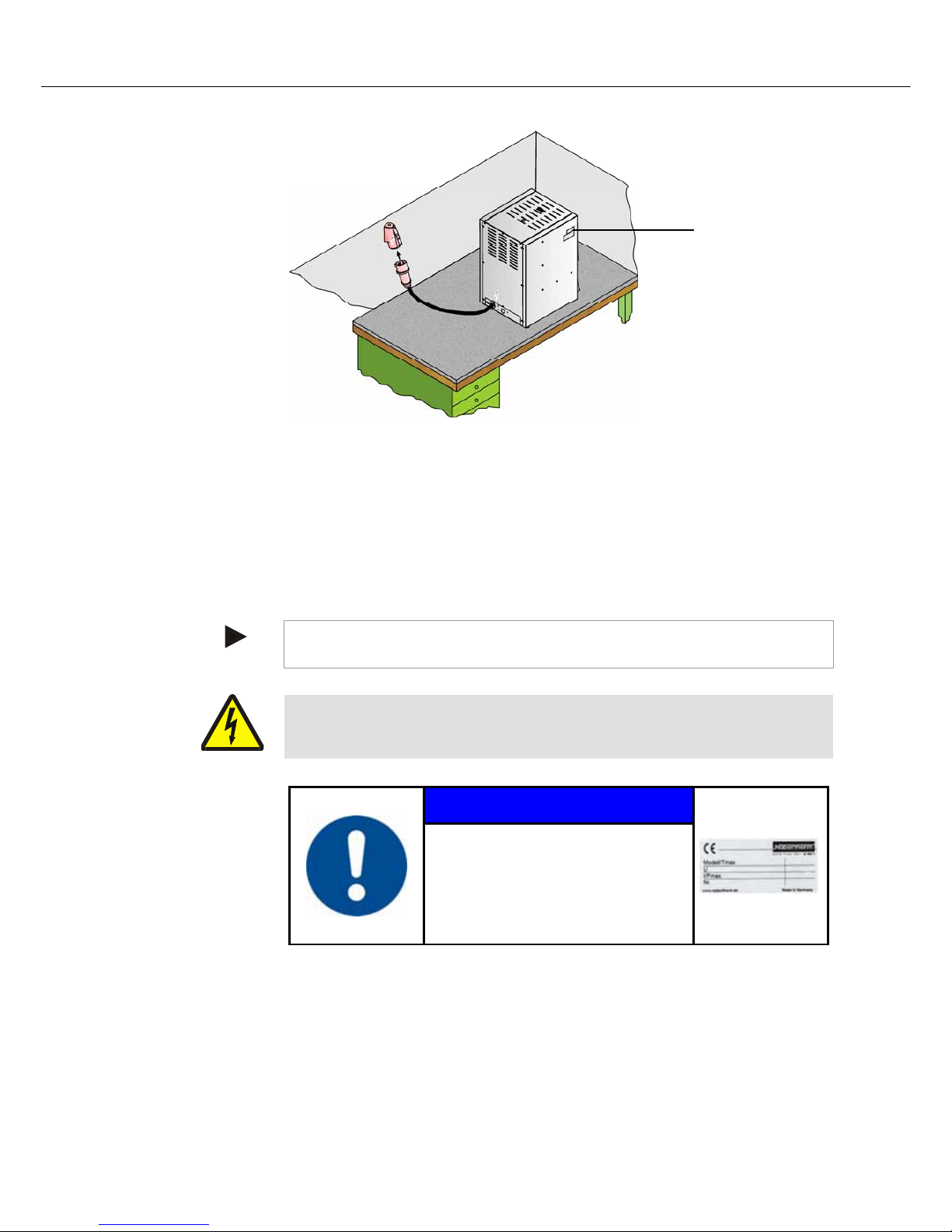
36
Pos: 124 /TD/Transport_Montage_Inbetriebnahme/Er s tinbetriebnahme/Anschluss an das Elektronetz - Labor ofen-3phasig mit Netzzuleitung @ 14\mod_13001133540 20_51.docx @ 113386 @ @ 1
Fig. 13: Power connection with power line
1. Connect the power cable to the power connection. Only use a socket with grounding
contact to supply power.
Grounding of the furnace and switching system (compliant with VDE 0100, part 410) is a
prerequisite for the current-operated e.l.c.b. system of the heater.
Test the ground resistance (compliant with VDE 0100); see also accident prevention
guidelines.
Electrical systems and equipment compliant with BGV A3.
Note
The national regulations of the country of operation apply.
Warning - danger due to electrical current!
Work on the electrical equipment may only be performed by qualified, authorized
electricians.
Pos: 125 /TD/Sicherheit/Sicherheitssymbole/W arnhinweise-ISO-ANSI/Warnsymbol_Achtung - falsc he Netzspannung - Piktogramm Gebotszeichen @ 9\mod_12474752 31381_51.docx @ 63131 @ @ 1
NOTICE
• Danger from incorrect voltage
• Damage to the furnace.
• Check voltage before connecting and
commissioning the furnace.
• Compare the voltage with the details
on the type plate.
Type plate
1.
Page 37

37
Pos: 126 /TD/Sicherheit/Sicherheitssymbole/W arnhinweise-ISO-ANSI/Warnsymbol_Gefahr - Brandgef ahr - Piktogramm Brandgefahr @ 9\mod_1247148035738_51.doc x @ 63010 @ @ 1
DANGER
• Fire- danger to health.
• Risk of fatal injury.
• Adequate ventilation must be ensured at the
installation location to conduct waste heat and any
exhaust gases away.
Pos: 127 /TD/Transport_Montage_Inbetriebnahme/Er s tinbetriebnahme/Überschrift - Einlegen der Bodenp la tte LHT-Ofen @ 2\mod_1185287183100_51.docx @ 20422 @ 3 @ 1
4.6.3 Insertion of the Base Plate
Pos: 128 /TD/Transport_Montage_Inbetriebnahme/Er s tinbetriebnahme/Einlegen der Einlegeplatte (Bodenp latte) HT 04/16-HT 450/18-Öfen - Text (1) @ 21\mod_13311106137 20_51.docx @ 151215 @ @ 1
Carefully place the insert plate(s) *) (number of insert plates depends on the furnace
model), distributed across the floor of the furnace, starting from the middle. When placing
the insert plate(s) make sure that neither the door collar nor the heating elements are
damaged. Absolutely avoid touching the heating elements when inserting the heating
plate(s). Contacting the heating elements can result in their immediate destruction.
The furnace floor is made of high-quality refractory material but this material is highly
sensitive to impact or pressure.
Some models are supplied with one insert plate as a standard in order to prevent the soft
furnace floor from being damaged. Nabertherm accepts no liability for damage (e.g.
depressions) in the furnace floor resulting from not using these insert plates. *) Damaged
insert plate(s) must be immediately replaced with new ones (see the section "Spare
Parts/Wearing Parts").
The charge must be positioned in the furnace chamber, on the floor, as centered as possible.
This ensures uniform heating.
After charging, the furnace door must be closed carefully.
*) in scope of delivery depending on the design/furnace model
Pos: 129 /TD/Transport_Montage_Inbetriebnahme/Er s tinbetriebnahme/Hinweis - Es ist darauf zu achten, dass die B e lastung des Bodens 2 kg/dm2 nicht überschreitet @ 2\mod_11852 87451644_51.docx @ 20435 @ @ 1
Note
It must be ensured that the load on the furnace base does not exceed 2 kg/dm
2
.
Pos: 130 /TD/Transport_Montage_Inbetriebnahme/Er s tinbetriebnahme/Einlegen der Einlegeplatte (Bodenp latte) LHT/HTC/HTCT-Öfen - Grafik (1) @ 21\mod_1331045 3140 67_51.docx @ 151165 @ @ 1
In scope of delivery depends on design/furnace model
Fig. 14: Inserting the ceramic insert plate
Pos: 131 /TD/Transport_Montage_Inbetriebnahme/Er s tinbetriebnahme/Laboröfen - Montage der Waage am L(T).../.../SW-Ofenmodell @ 14\mod_1300119303359_51.docx @ 113570 @ @ 1
Page 38

38
Installing the Scale on the L(T).../.../SW Model
Insert the ceramic stamp included in the scope of delivery from below into the hole
in the floor of the furnace.
Place the scale in the frame under the furnace. At the same time raise the pipe
carefully and place it on the supporting surface of the scale.
To hold the pipe in place the support die must be slide into the space between the
pipe and the supporting surface of the scale. This is done by carefully raising the pipe.
In the furnace chamber, slide the ceramic plate with its guide onto the pipe and
orient it precisely. The pipe must be free-standing on the scale and must not have any
contact with the furnace insulation to avoid falsifying the measurement results.
Connect the scale with the power plug.
The function of the scale: This information can be found in the instructions enclosed
with the scale.
Separate instruction manual for MV software (optional)
Fig. 15: Scale
Pos: 132 /TD/Transport_Montage_Inbetriebnahme/Er s tinbetriebnahme/Überschrift - Erstinbetriebn ahme @ 0\mod_1167828977720_51.docx @ 5337 @ 2 @ 1
4.7 Commissioning
Pos: 133 /TD/Transport_Montage_Inbetriebnahme/Er s tinbetriebnahme/Erstinbetriebnahme LHT/N/NR/ TR/NAC/RHTH-RHTV - Öfen - 1 @ 2\mod_1186641509092_51.doc x @ 20833 @ @ 1
The furnace may be put into operation only by qualified persons and in compliance with the
safety instructions.
Read the section on "Safety". When the furnace is put into operation, the following safety
information must also be observed to prevent serious injury, damage to the furnace, and
damage to other property.
Make sure that the instructions and information in the controller instructions are observed
and followed.
The furnace may be used only for its intended purpose.
Ensure that only authorized persons remain in the working area of the furnace and that no
other persons are put at risk when the furnace is put into operation.
1
2
3
4
1
2
3
4
Page 39

39
Before starting the furnace for the first time, make sure that all tools, foreign parts, and
transportation securing equipment have been removed.
Activate all safety equipment (power switch, emergency stop button if applicable) before
putting the furnace into operation.
Incorrectly wired connections may destroy electric/electronic components.
Observe the special protective measures (e.g. grounding, …) for components that are at
risk.
Faulty connections can cause the furnace to start unexpectedly.
Before you switch on the furnace, make sure that you know what to do in case of faults or
emergencies.
Before starting the furnace for the first time, check the electrical connections and control
displays.
Before placing materials in the furnace, check whether they could harm or destroy the
insulation or the heating elements. Materials that could damage the insulation include:
alkalis, alkaline earths, metal vapors, metal oxides, chlorine compounds, phosphorous
compounds, and halogens.
Pos: 134 /TD/Allgemeine Hinweise (für alle Anleitungen)/ Hinweis - Vor Inbetriebnahme des Ofens sollte dieser 24 Stun den am Aufstellungsort akklimatisiert .. @ 3\mod_1195568 014336_51.docx @ 27871 @ @ 1
Note
Before starting the furnace for the first time, allow it to acclimatize at its installation
location for 24 hours.
Pos: 135 /TD/Transport_Montage_Inbetriebnahme/Er s tinbetriebnahme/Überschrift - Empfehlung für das erste Aufheizen des Ofens @ 0\mod_1167829134269_51.doc x @ 5346 @ 2 @ 1
4.8 Recommendations for Heating the Furnace for the First Time
Pos: 136 /TD/Transport_Montage_Inbetriebnahme/Er s tinbetriebnahme/Empfehlung für das erste Aufheizen de s Laborofens L-LE-L(T)-LV(T)-SKM-SW-HA @ 14\mod_130 0196 013048_51.docx @ 113620 @ @ 1
The furnace must first be heated up to dry out the masonry and generate a protective
oxidated layer on the heating elements.
During the heating up the furnace may give off unpleasant odors, which is due to the
release of binding agents from the insulation material. We recommend that the furnace
location be well ventilated during the first warm-up phase.
Warm up the empty furnace over a period of roughly 6 hours
1)
to 1050 °C (1922 °F).
Hold this temperature for roughly 1 hour.
Warm up LE …/… models to 1000 °C (1832 °F) (without the warm-up ramp).
After the first warm-up phase, let the furnace cool down naturally to room
temperature.
The furnace is now ready to operate
1) Warm-up ramp
Caution
This procedure must be performed at the time the furnace is commissioned, following the
replacement of heating elements or to regenerate the oxidated layer.
Pos: 137 /TD/Betrieb_Bedienung/Überschrift - Beschickung/Chargierung @ 0\mod_1167835476044_51.docx @ 541 8 @ 2 @ 1
4.9 Loading/Charging
Pos: 138 /TD/Transport_Montage_Inbetriebnahme/Er s tinbetriebnahme/Beschickung des Laborofens L-LE- L( T)-LV(T)-SKM-SW-HA @ 14\mod_1300202800375_51.doc x @ 113716 @ @ 1
Charging the Furnace
The insulation is made of high-quality refractory material but is highly sensitive to impact.
Avoid contact when charging to prevent any damage.
To obtain a temperature distribution which is as uniform as possible it is advantageous to
leave space between the pieces and between the pieces and the side walls. Nabertherm
supplies insert plates (base plate) and the like to help you make use of the furnace chamber.
Page 40

40
Loading a very large quantity of ware into the furnace chamber can substantially lengthen
the heating-up time.
The furnace heating system is interrupted if the door is opened. After the door is reclosed, it
is automatically switched on again (not applicable to LE …/… models).
If it can be at all avoided, do not open the furnace when it is hot. When it is necessary to
open the furnace at a high temperature, the time should be kept to an absolute minimum.
Make sure that operators wear the appropriate protective clothing and that the workspace is
adequately ventilated.
Always make sure that the door is completely closed.
Stainless steel sheet can discolor (especially if the furnace is opened while hot). This does
not impair functionality in any way. This is no reason for a complaint.
Caution LE …/… Models:
Continuous operation at maximum temperature can lead to increased wear of the heating
elements and the door seal. We recommend operating at approx. 50 °C below the
maximum temperature.
Caution for LT …/…HA Models:
The recirculating air motor starts when the program begins and cuts out again automatically
when the program ends and the furnace chamber temperature has dropped to below 80 °C
(176 °F). Above this temperature the furnace must not be switched off or disconnected
from its power source. If this caution is not observed the recirculating air motor may be
damaged.
Warning - Danger of Electric Shock!
For the protection of the operator and the furnace the heating program must be stopped
before the furnace is loaded. Ignoring this warning can result in electric shock.
Pos: 139 /TD/Transport_Montage_Inbetriebnahme/Er s tinbetriebnahme/Risse in der Isolierung und an den sei tlic hen keramischen Platten @ 14\mod_1300198786191_51.doc x @ 113693 @ @ 1
Cracks in the Insulation
The insulation of the furnace and/or the side heating plates in the furnace (depending on the
furnace model) are made of very high-quality refractory material. Thermal expansion
causes cracks in the insulation even after only a few warm-up cycles and, in some
circumstances, in the side heating plates as well. But these have no impact on the function
or quality of the furnace. This is no reason for a complaint.
Before After
Fig. 16: Example: Cracks in the insulation after a few warm-up cycles.
Page 41

41
Pos: 140 /TD/Betrieb_Bedienung/Zulufthebel für Hubtür - und Klapptürmodellen mit Katalysator-Abluftgebl äse und LV-Modelle - 2 @ 3\mod_1188983024989_51.docx @ 21131 @ @ 1
D
Notice for the Use of Catalytic Converters and Exhaust Vent Fan:
The air feed lever must always be set to because the exhaust gases cannot be adequately
vented from the furnace chamber.
Information for LV/LVT …/… Models:
These models have an independent, air feed system which cannot be regulated. The fresh
air is fed through holes in the back wall into the upper heating plate where it is pre-heated
and comes back out in front, above the furnace chamber. In the setting of the air feed
lever fresh air is also fed in which is not pre-heated. For complete feed air pre-heating
select the setting. During protective gas connection/operation the lever must be set to
.
Pos: 141 /TD/Betrieb_Bedienung/Überschrift - Bedienung 1 @ 3\mod_1186740685002_51.docx @ 20988 @ 1 @ 1
5 Operation
Pos: 142 /TD/Betrieb_Bedienung/Überschrift - B edi enung - Controller B 180/P 330 1.1 @ 9\mod_1249568365976_51.docx @ 64713 @ 2 @ 1
5.1 Operating Controller B 180/P 330
Pos: 143 /TD/Betrieb_Bedienung/Bedienung Laborofens L- LE-L(T)-LV(T)-SKM-SW-HA ... Controller B180/P330 @ 14\ mod_1300204429027_51.docx @ 113799 @ @ 1
Fig. 17: Example: Controller
1. The control power is switched on and off with the power switch (1). When the
control voltage is switched on the heating space temperature is displayed by the controller
(2) in the LED.
2. The desired heating and cooling program is set at the controller (2). The description
of the controller is in a separate instruction manual.
3. Temperature value of the over-temperature limiter (3) (optional) must be set 30 °C
higher than the setting on the controller. Description of the over-temperature limiter
(OTL) is contained in the instruction manual of the controller B 180/P 330.
Caution
Continuous operation at maximum temperature can lead to increased wear of the heating
elements and the door seal. We recommend operating at approx. 50 °C below the
maximum temperature.
Caution
Description of the controller B 180/P 330 is contained in a separate instruction manual.
2132iEurotherm
27x12,7
2
OFF/ON
1
3 (optional)
Page 42

42
Pos: 144 /TD/Betrieb_Bedienung/Überschrift - B edi enung - Controller R6 1.1 @ 9\mod_1249568510166_51.docx @ 64730 @ 2 @ 1
5.2 Operating Controller R 6
Pos: 145 /TD/Betrieb_Bedienung/Bedienung Controller R6 @ 9\mod_1249472399873_51.docx @ 64633 @ @ 1
Fig. 18: Controller R 6
Key Description Display
Switch on furnace I
The furnace is switched on and off with the power switch " ". When the
power is switched on, the current furnace temperature (actual temperature) is
shown on the controller display (Example: °C).
When the K1 lamp " " remains on, this means that the controller is ready.
Press
To adjust the required furnace temperature (temperature set point), press the
" " button once. The display alternates between " " and the last
temperature set point in the entry level (Example: °C)
Press
Use the " " buttons to set the required furnace temperature
(temperature set point) between °C and °C (Example: °C)
Increase the value with ( … , )
Reduce the value with ( … , )
Wait 2 seconds until the new temperature set point is integrated automatically (display flashes
1x)
(For the required temperature set point you can choose a temperature range from 5°C above
room temperature to 300°C).
Press
(or the display changes
automatically after 15 seconds)
The display changes automatically after 15 seconds or if you press the " "
button again
(The current furnace temperature is displayed. Example °C).
Switch on heating I The heating process is started.
Use the " " switch to switch the heating on and off.
When the K2 lamp " " flashes, this means that the heating is ready.
Press
You can check the temperature set point at any time with the " " button.
= Set point
P
K1 K2
P
P
P
P
P
P
OFF/ON
OFF/ON
Display
Page 43

Pos: 146 /TD/Betrieb_Bedienung/Überschrift - Temperaturwählbegrenzer mit einstellbarer Abschaltte mperatur 1.1
@
5.3 Ov
eTem
Pos: 147 /TD/Betrieb_Bedienung/Bedienung Temperatur wählbegrenzer (TWB) Eurotherm 2132i @ 10\mod_12530
2
Key
@
9\mod_1250158374029_51.docx @ 65123 @ 2 @ 1
r-Temper
a
perature
2
5652302_51.docx @ 65993 @ @ 1
260 °C
270 °C
ture Lim
Fig. 19: O
v
Descriptio
n
The over-t
e
temperatur
e
temperatur
e
exceeds th
e
protect the
temperatur
e
When the t
e
on the ove
r
p
ressed to
r
operate:
Release he
Press
temperatur
e
Adjust the
Set the req
u
(Example
2
Increase th
e
Reduce the
To change
t
longer.
Wait 2 secon
d
flashes 1x).
Note:
Premature tri
g
b
etween the a
d
not below 10
°
The displa
y
temperatur
e
Entry finis
h
For more i
n
Eurotherm
ter with
M
er-temperatu
r
mperature li
m
in the furna
c
that was set.
set trigger te
m
furnace and t
h
limiter.
mperature i
n
-temperatu
r
elease the he
a
a
ting:
and si
m
limiter is re
s
trigger tem
p
ired trigger t
e
70 °C)
value with
value with
he value qui
c
s until the new t
r
gering of the ov
e
justable temper
a
C.
jumps back
t
. The curren
t
ed.
formation ab
o
2132i
anual R
e
e limiter wit
h
iter with ma
n
e chamber.
T
If the tempe
r
mperature, th
e load. "FS
H
the furnace
c
e limiter , th
e
ting so that t
h
ultaneously.
T
et and this re
l
erature:
mperature
w
(260 …
2
(270 …
2
kly: hold the
igger temperatu
r
-temperature li
m
ture in the furna
c
o the start sc
r
trigger temp
e
out operation
,
set and
A
manual rese
t
ual reset mo
n
he display sh
o
ature in the f
u
e heating is s
w
" alarm flash
e
hamber falls
b
following b
u
e furnace ca
n
he alarm on
t
eases the he
a
ith the
69, 270)
61, 260)
bu
e is integrated a
u
iter can be avoi
d
c
e chamber and
t
een showing
rature is dis
p
see the sepa
r
2132
i
djustable
2132i
itors the
ws the last t
r
rnace chamb
e
itched off to
s on the ove
r
elow the va
l
ttons have to
continue to
t
he over-
t
ing.
button
tton depresse
tomatically (dis
p
ed if the differe
n
h
e trigger tempe
r
the trigger
layed.
ate instructio
n
Cut-Off
Dis
p
igger
er
-
260
FS
H
l
ue set
be
d for
lay
n
ce
ature is
260
270
n
s for the
4
3
lay
°C
270
°C
Page 44

44
Pos: 148 /TD/Sicherheit/Sicherheitssymbole/W arnhinweise-ISO-ANSI/Warnsymbol_Gefahr - Absicherung von Gef
a
Pos: 149 /TD/Betrieb_Bedienung/Überschrift - Zulufthebel @ 3\mod_1188982021389_51.docx @ 21118 @ 2 @ 1
5.4 Air
I
Pos: 150 /TD/Betrieb_Bedienung/Zulufthebel für Hub tür - und Klapptürmodellen - 1 @ 3\mod_1188977524741_51.
d
D
Pos: 151 /TD/Betrieb_Bedienung/Zulufthebel für Hubtür - und Klapptürmodellen mit Katalysator-
A
bluftgebläse und
LD a
hren bei Übertemperatur am TWB-TWW @ 37\mod_1362490404893_51. docx @ 214067 @ @ 1
nflow Le
v
d
ocx @ 21106 @ @ 1
LV
-Modelle - 2 @ 3\mod_1188983024989_51.docx @ 21131 @ @ 1
er
The volum
e
lever is loc
a
symbols b
e
F
i
g
.
20
:
F
r
e
s
Fig. 1: Fre
s
Fresh air l
max. ope
n
Fig. 21: Re
Notice fo
r
The air fee
d
vented fro
m
Informati
o
These mod
e
air is fed t
h
and comes
b
•
•
•
of air fed to
ted at the si
d
side and on t
h
h air lever (fi
g
e
ver is
g
ulating the
fe
the Use of
lever must
a
the furnace
c
n for LV/L
V
ls have an in
rough holes i
n
b
ack out in fr
o
Danger cau
s
temperatur
e
manual rese
t
reset.
Mortal dan
g
If, as a resul
t
operating e
q
set cut-off t
e
manual rese
t
the charge i
t
surrounding
s
over-temper
a
maximum p
e
the furnace c
a
e of the door
e lever.
gure similar)
eed of fresh
a
Catalytic C
lways be set
t
chamber.
T …/… Mo
d
dependent, ai
r
the back w
a
ont, above th
e
ed by incor
r
at the over-
t
/over-tempe
er
of over-tem
p
uipment, a c
h
mperature of
/over-temper
a
self becomes
, the cut-off
t
a
ture limiter
w
rmissible va
l
a
n be adjuste
d
at the bottom
.
ir (symbols)
onverters a
o becaus
e
els:
r
feed system
ll into the up
p
furnace cha
m
DANGE
R
ectly entere
d
emperature
r
ature limite
erature from
t
arge is likely
the ove
r
-tem
p
ture limiter
w
a source of d
a
emperature
m
ith manual r
e
ue.
with the fre
s
The positio
n
nd Exhaust
the exhaust
g
which canno
t
er heating pl
a
ber. In the
cut-off
limiter with
r with auto
m
the charge an
to be damag
e
erature limit
e
ith automati
c
nger for the
f
ust be reduc
e
e
set/automati
c
h air lever. T
h
is explained
Fresh ai
r
close
d
Vent Fan:
ases cannot
b
be regulated
te where it i
s
setting of t
h
atic
d
/or the
d at this pre-
r with
reset, or if
urnace or its
d at the
reset to the
h
e fresh air
b
y the
lever is
e adequately
. The fresh
pre-heated
e air feed
Page 45

45
lever fresh air is also fed in which is not pre-heated. For complete feed air pre-heating
select the setting. During protective gas connection/operation the lever must be set to
.
Pos: 152 /TD/Betrieb_Bedienung/Hinweis - Zulufthebe l für Hubtür- und Klapptürmodellen - Temperaturgleichmäßi gkeit - 2 @ 12\mod_1283334296574_51.docx @ 97705 @ @ 1
Note
If the fresh air lever is open, under certain circumstances this may affect temperature
uniformity in the furnace chamber.
Pos: 153 /TD/Wartung_Reinigung_Instandhaltung/Ü ber schrift - Wartung, Reinigung und Instandhaltung @ 0\ mod_ 1167 835785730_51.docx @ 5436 @ 1 @ 1
6 Servicing, Cleaning, and Maintenance
Pos: 154 /TD/Wartung_Reinigung_Instandhaltung/W artung, Reinigung und Instandhaltung - Laboröfen @ 3\mod_11 8890 8437969_51.docx @ 21071 @ @ 1
Warning! General Hazards!
Cleaning, lubrication, and maintenance tasks may only be performed by authorized experts
following the maintenance instructions and accident protection guidelines. We recommend
that maintenance and repair be performed by Nabertherm GmbH Service. Failure to comply
runs the risk of bodily injury, death, or significant property damage!
Warning - Danger due to Electrical Current!
Work on the electrical equipment may only be performed by qualified, authorized
electricians!
During maintenance work, the voltage supply to the furnace and/or switching system must
be switched off to prevent unintentional commissioning. Disconnect the mains power
connector due to reasons of safety.
Operators may only correct malfunctions which are obviously due to operational error!
Wait until the furnace chamber and attaching parts have cooled to room temperature.
The furnace must be visually inspected at regular intervals for damage. The interior of the
furnace must also be cleaned as required (e.g. vacuuming out) Attention: Do not bang
against the heating elements to avoid breaking them.
While work is being performed on the furnace, the furnace and work room must
additionally be ventilated with fresh air.
Safety systems removed during maintenance tasks must be replaced after the work.
Warning of swinging loads in the workshop (e.g. crane systems). Work under a lifted load
(e.g. a lifted furnace or switching system) is not permitted.
Safety switches and any limit switches present must be checked for function periodically
(BGV A3) or according to the national guidelines of the country of operation.
To ensure proper temperature regulation of the furnace, the thermocouple must be checked
for damage before every process.
If necessary, retighten the element holders (see chapter "Replacing the Heating Element").
Before carrying out this work, the voltage supply to the furnace and/or switching system
must be switched off (disconnect mains power connector). The regulations (BGV A3) or
corresponding national regulations in the relevant country of operation must be observed.
There are one or more contactors in the control system. The contacts of these circuit
breakers are wearing parts and must therefore be serviced and/or replaced regularly (BGV
A3) or according to the national guidelines of the country of operation.
The switching system cabinet (if available) contains vent grilles with integrated filter mats.
These must be cleaned and/or replaced at regular intervals in order to ensure sufficient
intake and outflow of air from the switching system. During melting operation, the
switching cabinet door must always be firmly closed.
Page 46

46
Pos: 155 /TD/Allgemeine Hinweise (für alle Anleitungen)/ Hinweis - Dieser Ofen enthält in der Isolierung keramisc h
e
Pos: 156 /TD/Wartung_Reinigung_Instandhaltung/Ü ber schrift - Stillsetzung der Anlage für Wartungsarbei te n @ 0\
m
6.1 Shu
Pos: 157 /TD/Wartung_Reinigung_Instandhaltung/Sti llsetzung der Anlage für Wartungsarbeiten @ 15\mod_1304 6
7
Pos: 158 /TD/Sicherheit/Sicherheitssymbole/W arnhinweise-ISO-ANSI/Warnung - Berühren Sie keinen Gegens tand
,
e
s Fasermaterial. @ 3\mod_1190114970393_51.docx @ 21866 @ @ 1
m
od_1167835907715_51.docx @ 5445 @ 2 @ 1
tting the
S
7
1946911_51.docx @ 116773 @ @ 1
, ohne ihn zuvor auf seine Temperatur überprüft zu haben. @ 25\ mod _134 1394122108_51.docx @ 166785 @ @ 1
This Fur
n
Active han
d
Germany i
s
N
o. 7 ("Ar
t
ceramic fi
b
December
5
therefore b
e
The Follo
w
- Dust dev
e
- Contact
w
fibers o
n
which re
d
- When pr
o
long sle
e
- When w
o
with P2
f
The furnac
e
regulations
national re
g
ystem D
o
Warning!
Cleaning, l
u
following t
h
that mainte
n
runs the ris
k
Wait until
The f
u
Infor
m
Switc
h
Lock
t
p
adlo
c
Attac
h
Clean
Chec
k
Grou
n
Cove
r
Warning
-
Do not tou
c
ace contai
n
ling of these
subject to th
e
ificial miner
a
ers are categ
o
, 1997 CAR
C
done in suc
h
ing Point
s
lopment dur
i
ith skin and
e
the skin or i
n
dening and i
cessing larg
e
ves, gloves a
n
rking with c
e
ilter should a
and its oper
a
of the emplo
y
ulations in t
h
wn for
M
General Ha
brication, a
n
e maintenan
c
n
ance and re
p
k
of bodily in
j
the furnace
c
rnace must b
operating p
e
off main s
w
he main swit
c
k.
a warning s
i
up the maint
e
for disconne
d and short-c
any nearby
p
Dangers D
h any object
s Ceramic
F
fibers (e.g.,
e
e
conditions
o
l fibers") of J
u
rized as foll
o
. Cat. 2; R 4
a way that a
must be N
o
ng processin
g
e
yes should b
the eyes ma
y
tching may o
c
quantities of
d safety glas
ramic fiber i
n
dditionally b
e
ting equipm
e
er's liability
e relevant co
u
aintenan
c
zards!
d maintenan
c
c
e instruction
air be perfor
m
ury, death, o
r
hamber an
d
e completely
rsonnel and
n
itch and/or d
i
ch (if availab
l
gn on the ma
i
nance area a
s
ction of pow
e
ircuit the wo
r
arts still und
e
uring Nor
m
without first
h
iber Mater
i
xchange of t
h
f the Ordina
n
u
ne 12, 1998.
ws by Direct
i
9
; Xi R 38.
W
s little fiber d
u
o
ted when
H
should be
m
e avoided. T
h
cause mech
a
cur.
ceramic fibe
r
ses should be
sulation insi
d
worn.
nt must be re
i
nsurance ass
o
ntry of use!
e
e tasks may
o
s and acciden
t
ed by Nabe
r
significant
p
attached pa
emptied
ame supervi
s
sconnect the
p
e) and secur
e
n switch
far as possi
b
r.
king area.
r power.
al Operatio
n
aving check
e
al in the In
s
e insulation)
i
ce on Hazard
In the rest of
ve 97/69/EC
o
ork with the
f
st as possibl
e
andling C
e
i
nimized.
e effects cau
s
nical irritatio
n
s, loose wor
k
worn.
e furnaces, a
h
g
ularly check
ciation (BG
V
nly be perfor
m
t
protection g
u
therm GmbH
roperty dama
g
ts have cool
e
ors
ower cord.
against resto
r
le.
!
d its tempera
t
ulation.
in the Federa
l
ous Substanc
e
the Europea
n
of the Comm
i
f
iber insulati
o
is released.
ramic Fibe
r
ed by
n, as a result
o
clothing wit
h
half/quarter
m
ed in accord
a
A3) or the
c
ed by autho
r
u
idelines. W
e
Service. Fail
u
ge!
ed to room t
e
r
ation of pow
ture.
Republic of
s, Annex V,
Union,
ssion of
n must
:
f
ask
n
ce with the
orrespondin
g
ized experts
recommend
re to compl
y
mperature.
e
r using a
Page 47

Pos: 159 /TD/Ersatz-/Verschleißteile/War nung - Gefahren durch elektrischen Strom - Netzstecker ziehen - f ür alle
Ö
Pos: 160 /TD/Wartung_Reinigung_Instandhaltung/Ü ber schrift - Wartungsarbeiten am Ofen @ 0\mod_1167836306
6
6.2 Reg
Pos: 161 /TD/Wartung_Reinigung_Instandhaltung/Rege lmäßige Wartungsarbeiten (Wartungstabelle) H TCT 01/16
_
Position/
Maintenan
c
Safety test in a
c
with BGV A3
o
corresponding
n
regulations
Safety and
limit switches
(if available)
Furnace chamb
outlets and flu
e
Seal surfaces:
door lining/fur
n
Heating eleme
n
Check for even
consumption o
f
Thermocouple
Check the setp
o
over-temperatu
included)
Key:
Fig. 22: Mai
n
Pos: 162 /TD/Allgemeine Hinweise (für alle Anleitungen)/ Warnung - Arbeiten an der elektrischen Ausrüstung dürfe
n
Pos: 163 /TD/Allgemeine Hinweise (für alle Anleitungen)/ Hinweis - Wartungsarbeiten dürfen nur von autorisi er ten F
a
Ö
fen @ 3\mod_1189491390787_51.docx @ 21273 @ @ 1
6
81_51.docx @ 5463 @ 2 @ 1
ular Main
t
_
HTC 01/15-Renishaw und M01.0032 @ 10\mod_1255433729380_51. doc x @ 67002 @ @ 1
e Point
M
cordance
r
ational
Are
F
er, flue
C
d
c
ace lining
V
ts
V
p
e
c
power
heating
F
V
pth
f
u
int oft he
re limiter (if St
e
t
e
c
t
e
■
tenance tabl
e
n
nur von ... @ 2\mod_1184228021019_51.docx @ 19673 @ @ 1
F
achpersonen unter Beachtung von ... @ 1\mod_1173971704689_51.docx @ 11131 @ @ 1
Warning
-
Work on t
h
During wo
r
activated b
y
secured. O
b
the furnace
temperatur
e
t
enance
o
easure
ccording to
gulations
unction test
lean and check
f
amage, vacuum
o
arefully
isual check
isual check (vis
i
art of the heatin
g
lement in the fur
n
hamber)
unction test
isual check (vis
i
art of the
ermocouple in t
h
rnace chamber)
et the cut-off
mperature at th
e
mperature limi
t
e
orrectly for the c
h
mperature.
= clean
Warning
-
Work on t
h
Note
Maintenan
c
instruction
s
and repair
w
Danger of
e electrical e
q
k it must be
e
mistake (pu
l
serve BGV
A
is installed.
W
.
f the Fur
n
Main
Day
Accor
d
or
ut
●
ble
ace
●
ble
e
●
over-
r
h
arge
●
● = check
Danger of
e electrical e
q
e work must
and the acci
d
ork be carri
e
Electric Sh
o
uipment ma
y
nsured that t
h
ll out the po
w
3 or the corr
e
ait until the
ace
tenance Inte
r
Week
ing to regulatio
n
, replace
Electric Sh
o
uipment ma
y
be performe
d
ent preventi
o
d out by the
s
ck!
be done onl
y
e furnace an
d
er plug) and
t
sponding na
t
furnace and t
h
val
Month
Q
s
■
x = perfor
m
ck!
be done onl
y
by authorize
d
n regulations
ervice team
o
by qualified
,
the switchin
g
hat all movin
g
ional regulati
e connected
p
uarter
Y
●
●
ance by
by qualified
,
personnel f
o
. We recom
m
f Naberther
m
authorized e
l
g equipment
c
g parts in the
ons in the co
u
parts have co
o
Op
e
g
ear Per
s
x
x
x
x
x
authorized e
l
llowing the
m
end that the
m
GmbH.
4
7
ectricians.
annot be
furnace are
ntry where
led to room
ratin Qua
l
ed
onnel
x
x
x
ectricians.
aintenance
aintenance
ifi
Page 48

48
Pos: 164 /TD/Wartung_Reinigung_Instandhaltung/Ü ber schrift - Betrieb- und Hilfsmittel @ 0\mod_116783716145 8_51.docx @ 5499 @ 2 @ 1
6.3 Operating and Auxiliary Materials
Pos: 165 /TD/Wartung_Reinigung_Instandhaltung/Ü ber schrift - Reinigungsmittel 1.1 @ 0\mod_1167837229988_ 51.docx @ 5508 @ 2 @ 1
6.4 Cleaning Products
Pos: 166 /TD/Wartung_Reinigung_Instandhaltung/Rei nigungsmittel (für alle Öfen) @ 0\mod_1158657592397_51. docx @ 2843 @ @ 1
Follow the procedure for shutting down the furnace system (in the "Operation" section).
Then the power plug must be pulled out of the socket. Wait until the furnace cools down
naturally.
Use commercially available detergent which is either water-based or non-combustible and
free of any solvents to clean the housing of any deposits; use a vacuum cleaner for the
interior.
Follow the labeling and the instructions on the packaging of the detergent.
Wipe the surface with a damp, lint-free cloth. The following detergents can also be used:
This list must be completed by the operator.
Component and
location
Detergent
Outer surfaces
(frames *)
Use commercially available detergent which is either water-or noncombustible and free of any solvents for cleaning *)
Outer surface
(stainless steel)
Stainless still cleaner
Interior Carefully clean with a vacuum cleaner
(avoid the heating elements)
Insulation materials Carefully clean with a vacuum cleaner
(avoid the heating elements)
Door seal
(if included)
Use commercially available detergent which is either water-or noncombustible and free of any solvents for cleaning
Instrument panel Wipe the surface with a damp, lint-free cloth. (e.g. glass cleaner)
*)
You must be sure that the cleaner does not damage the water-soluble and, hence, environmentally safe
paint (the clear should be tried first on an interior, normally unseen location).
Fig. 23: Detergent
Do the cleaning from beginning to end without breaks to protect the surfaces.
Remove the detergent completely from the surfaces by wiping them with a damp, lint-free
cloth.
After cleaning all the supply lines, check all the connections for leaks, loose connections,
abrasion and damage; report any shortcomings found immediately!
Please follow the section entitled "Environmental Protection Rules and Regulations"
Caution
The furnace, the furnace chamber and attached components must NOT be cleaned using a
high-pressure cleaner.
Page 49

49
Pos: 167 /TD/Sicherheit/Sicherheitssymbole/W arnhinweise-ISO-ANSI/Warnsymbol_Gefahr - Gefahren bei m Reinigen - Piktogramm Elektr.-Netzstecker- Spr itzen @ 9\mod_1247825736695_51.docx @ 63802 @ @ 1
DANGER
• Danger of electric shock.
• Risk of fatal injury
• Before cleaning, pull out the power
plug.
• Do NOT pour water or cleaning
products over the inside or outside
surfaces
• Allow furnace to dry completely before
operating it again
Pos: 168 /TD/Störungen/Fehlersuche/Öfen/Überschr ift - Störungen @ 0\mod_1167837724781_51.docx @ 5526 @ 1 @ 1
7 Malfunctions
Pos: 169 /TD/Störungen/Fehlersuche/Öfen/Störungs tabelle Ofen (allgemeine Hinweise) @ 1\mod_11713637504 59_5 1.docx @ 9646 @ @ 1
Work on the electrical system may be done only by qualified, authorized electricians.
Operators may only rectify malfunctions that are obviously due to operating errors.
Call the local electrician for malfunctions that you cannot localize.
If you have any questions, problems, or requirements, contact Nabertherm GmbH. By mail,
phone, or e-mail See "Nabertherm Service".
Pos: 170 /TD/Störungen/Fehlersuche/Öfen/Störungs tabelle Laboröfen/LHT-Tischmodell/HTC/Herdwagen öfen_1 @ 4\mod_1205479967638_51.docx @ 34312 @ @ 1
Type of malfunction Possible causes Malfunction rectification
Controller does not switch on. -No voltage available.
-Controller defective.
-Check connection fuse(s),
renew if necessary.
-Check controller fuses (if
available), renew if necessary.
-Check plug connector.
Controller indicates malfunction. -See separate instructions for
controller.
-See separate instructions for controller.
No heating chamber heating after
starting program.
-Error in program input.
-Connection fuse(s) defective.
-Heating element defective
-Check heating program (see
separate instructions for controller)
-Check connection fuse(s),
renew if necessary.
Notify
Nabertherm Service if the new
fuse trips on screwing in.
-Have checking carried out by
Nabertherm Service.
Very slow heating chamber
heating.
-Connection fuse(s) defective. -Check connection fuse(s),
renew if necessary.
Notify Nabertherm Service if the new
fuse trips on screwing in.
Selected end temperature is not
reached.
-Lack of heater output due to
undervoltage.
-Heating element defective
-Have checking carried out by
Nabertherm Service.
Page 50

50
Pos: 171 /TD/Ersatz-/Verschleißteile/Übersc hr ift - Sicherung austauschen 1.1 @ 9\mod_1249628090492_51. doc x @ 64803 @ 2 @ 1
7.1 Replacing a Fuse
Pos: 172 /TD/Ersatz-/Verschleißteile/Überschr ift - Sicherung befindlich außerhalb der Schaltanlage @ 23\ m od_1 335524783012_51.docx @ 156345 @ 3 @ 1
7.1.1 Fuse Located Outside the Switchgear
Pos: 173 /TD/Ersatz-/Verschleißteile/Einbauor t der Sicherung - Außerhalb des Schaltanlagengehäuses @ 23\mod _13 35939130737_51.docx @ 156460 @ @ 1
A fuse is located on the back of the furnace beside the power cable connection. The fuse is
an important component of the power supply system and protects the furnace and its
components against damage and fire. When you insert a new fuse, make sure that the fuse
rating is suitable for the voltage used by your furnace.
Pos: 174 /TD/Sicherheit/Sicherheitssymbole/W arnhinweise-ISO-ANSI/Warnsymbol_Achtung - Verwend ung ei ner Sicherung @ 23\mod_1335526283205_51.docx @ 156405 @ @ 1
NOTICE
• Damage to the furnace and its components
• Use of a fuse that is NOT suitable for the respective voltage
may damage the furnace and its components and is a fire
hazard.
• Use only a suitable fuse type. Check that the fuse type has the
correct nominal current value.
Pos: 175 /TD/Sicherheit/Sicherheitssymbole/W arnhinweise-ISO-ANSI/Befolgen Sie das Verfahren zu m Aussc halten der Ofenanlage (siehe ... @ 23\mod_1335940466853_ 51.docx @ 156485 @ @ 1
Carry out the procedure to switch off the furnace (see "Operation"). Then pull the power
plug out of the socket. Allow the furnace to cool naturally.
Pos: 176 /TD/Ersatz-/Verschleißteile/Sicher ung austauschen - Version A mit Werkzeug @ 9\mod_1249897945401_51. docx @ 64903 @ @ 1
Fig. 24: The fuse is located in the back wall of the furnace.
Insert a suitable flat blade screwdriver into the slot of the fuse holder. To remove the
fuse holder, press it in and turn it anti-clockwise. After a few turns, pull the fuse
holder out carefully with your fingertips.
Fig. 25: Release and pull out the fuse holder
Remove the fuse from the fuse holder.
Replace the defective fuse with a similar fuse.
Before you replace the fuse, make sure that it has the correct nominal current. For the
correct fuse (fuse link), see "Spare/Wearing Parts".
Fuse holder
Page 51

51
Fig. 26: Remove fuse
Note
The nominal current is engraved into the metal cap of the fuse or can be found imprinted
directly on the fuse.
Insert the new fuse into the fuse holder. Make sure that the fuse is pushed fully into
the holder.
Replace the fuse holder slowly and carefully. To fix the fuse holder, insert the flat
blade screwdriver into the slot and turn it in a clockwise direction with some pressure.
Fig. 27: Insert fuse
Check that the power cable is not damaged. The power cable must not be damaged.
Power cables may be replaced only with similar, approved cables.
Reconnect the power cable (see "Connecting the Furnace to the Power Supply")
Switch on the furnace's power switch (see "Operation")
Pos: 177 /TD/Ersatz-/Verschleißteile/Überschr ift - Sicherung befindlich innerhalb der Schaltanlage @ 23\ mod_1335518320707_51.docx @ 156320 @ 3 @ 1
7.1.2 Fuse Located Inside the Switchgear
Pos: 178 /TD/Ersatz-/Verschleißteile/Einbauor t der Sicherung - Innerhalb des Schaltanlagengehäuses @ 23\ mod_1335525353708_51.docx @ 156380 @ @ 1
A Fuse is located inside the switchgear cabinet. The fuse is an important component of the
power supply system and protects the furnace and its components against damage and fire.
When you insert a new fuse, make sure that the fuse rating is suitable for the voltage used
by your furnace.
T 16 A
H 500V
T 16 A
H 500V
Fuse (fuse link)
Nominal current
(Example)
Page 52

52
Pos: 179 /TD/Sicherheit/Sicherheitssymbole/W arnhinweise-ISO-ANSI/Warnsymbol_Achtung - Ver wendung ei ner S
i
Pos: 180 /TD/Sicherheit/Sicherheitssymbole/W arnhinweise-ISO-
A
NSI/Befolgen Sie das Verfahren zum Ausschalte
n
Pos: 181 /TD/Ersatz-/Verschleißteile/Demontage d er Schaltanlagenabdeckung -Text-Grafik @ 23\mod_133 5529 50
8
Pos: 182 /TD/Ersatz-/Verschleißteile/Sicher ung austauschen - Version C Sicherungshalterung - Laboröfen - Grafik
@
icherung @ 23\mod_1335526283205_51.docx @ 156405 @ @ 1
n
der Ofenanlage (siehe ... @ 23\mod_1335940466853_51. doc x @ 156485 @ @ 1
8641_51.docx @ 156430 @ @ 1
@ 33\mod_1353937962552_51.docx @ 199234 @ @ 1
Carry out t
h
plug out of
Removin
g
The numb
next.
Fig. 28: Re
Remove th
e
Fig. 29: In
s
•
•
•
e procedure
t
the socket. A
the switc
h
er and positi
m
ove rear w
a
screws fro
m
ert fuse
1
Damage to
t
Use of a fus
e
may dama
g
hazard.
Use only a s
u
correct nom
i
o switch off
t
llow the furn
a
gear cove
r
on of the sc
r
ll (figure sim
i
the rear wall
2
he furnace a
that is NO
T
e the furnac
e
itable fuse t
y
nal current v
a
he furnace (s
e
ce to cool na
t
ews may di
f
lar
and keep the
m
NOTICE
n
d its compo
suitable for
and its com
p
pe. Check th
a
lue.
e "Operatio
n
urally.
fer from on
e
in a secure
nents
the respecti
v
ponents and
t the fuse ty
p
"). Then pull
furnace m
o
place for late
r
3
e voltage
is a fire
e has the
the power
del to the
use.
Page 53

53
Pos: 183 /TD/Ersatz-/Verschleißteile/Sicher ung austauschen - Version C Sicherungshalterung - Beschr ei bung @ 23\mod_1335946646277_51.docx @ 156510 @ @ 1
Remove the fuse from the fuse holder.
Replace the defective fuse with a similar fuse.
Before you replace the fuse, make sure that it has the correct nominal current.
Fig. 30: Fuse (fuse link)
Note
The nominal current is engraved into the metal cap of the fuse or can be found imprinted
directly on the fuse.
Insert the new fuse into the fuse holder. Make sure that the fuse is pushed fully into
the holder.
Check that the power cable is not damaged. The power cable must not be damaged.
Power cables may be replaced only with similar, approved cables.
Pos: 184 /TD/Ersatz-/Verschleißteile/Montage der vorher gelösten Teile erfolgt in umgekehrter Reihenfolge @ 23\ mod_1335949647529_51.docx @ 156535 @ @ 1
Note
Assemble the loosened parts in the reverse sequence.
Pos: 185 /TD/Betrieb_Bedienung/Überschrift - Snap-In-Kupplung (Stecker) vom Ofengehäuse trennen 1.1 @ 12\mod_1 2821 13872192_51.docx @ 96923 @ 2 @ 1
7.2 Separate the Snap-In Coupling (Plug) from the Furnace Housing
Pos: 186 /TD/Betrieb_Bedienung/Bedienung Snap-I n- Kupplung (Stecker) vom Ofengehäuse trennen @ 12\mod_12821141 56861_51.docx @ 96945 @ @ 1
With a small flat blade screwdriver carefully push the locking latch (1) upward while
pulling the plug (2) out of the coupling (3).
Fig. 31: Separate the snap-in coupling (plug) from the furnace housing
T 4 A
250V
T 4 A
250V
Nominal current (Example)
Page 54

54
Pos: 187 /TD/Ersatz-/Verschleißteile/Übersc hr ift - Ersatz-/Verschleißteile @ 0\mod_116412525205 6_51. docx @ 4
2
8 Spar
e
Pos: 188 /TD/Ersatz-/Verschleißteile/Ersatz-/ Verschleißteile allgemeiner Text -Ersatzteil e bes tellen-Verfügbarkeit v
o
Pos: 189 /TD/Ersatz-/Verschleißteile/Ersatztei lliste - Laborofen L-LE-L(T)-LV(T)-SKM-SW- HA @ 14\mod_1300284
9
Model
No. Desi
g
1 Fur
n
1.3 Fiber
1.2
2 Elec
t
2.1 Cont
r
2.2 Cont
r
2.3 Cont
r
2.4 Roc
k
2.5 G ba
c
2.6 G ba
c
2.7 G ba
c
2.8
Pow
e
(xx
=
3 Tool
s
3.1
*) = Quantit
y
Pos: 190 /TD/Ersatz-/Verschleißteile/Legende für Ersatzteile Trockenschrank @ 10\mod_1252578510636_51. docx
2
43 @ 1 @ 1
Parts/W
e
o
n Ersatz- und Versch @ 13\mod_1290428577708_51.docx @ 108720 @ @ 1
9
91707_51.docx @ 113846 @ @ 1
nation
ace
wool
rical/control
l
oller P 330
oller B 180
oller R 6
er switch
-up set 2 A
-up set 10
A
-up set 16
A
r cable
country cod
e
depending
o
x
@ 65905 @ @ 1
aring Pa
r
Ordering
Our Naber
t
considerab
l
can make t
h
p
arts easil
y
looking for
you. Spare
entitled "N
a
Availabili
t
Although
N
the short-t
e
advance. If
at Naberth
e
l
ers
required)
n need
Symbols
Can b
Can
b
NT Nabe
r
ts
Spare Part
s
herm Service
e production
em ready fo
r
and simply
d
in the spare
p
parts can be
o
bertherm Se
r
y
of Spare P
a
abertherm h
a
rm availabili
t
you need an
y
rm will be gl
a
Part
691
6
5201
5201
540
2
541
7
541
5
541
5
541
5
V00
1
e replaced by
e replaced b
y
therm Servic
e
:
team is avail
a
depth we del
i
delivery wit
h
irectly from
t
art list or in
t
rdered in wri
vice".
rts and We
a
s many spare
y of all of th
e
assistance
w
a
d to set asid
e
number
00518*)
00255
00254
00170
00200
00182
00215
00303
3xx
the customer
trained pers
o
required
ble to you al
l
ver most spa
r
in short dea
d
he factory. If
he separate s
p
ting, by phon
e
ring Parts:
parts and we
a
m. We reco
m
hen selecting
time for yo
u
with tools a
n
nnel with to
o
around the
w
e parts from t
lines. You ca
n
you fail to fi
n
are part list
w
or on the In
t
ring parts on
mend that ce
r
spare parts a
n
.
d
instructions
ls and instruc
t
orld. Due to
he warehous
e
n
order Nabe
r
d the spare p
a
e would be
h
ernet -> see
t
stock, we ca
n
tain parts be
o
d wearing p
a
.
tions.
our
overnight or
therm spare
rt you are
appy to help
h
e section
not guaranty
rdered in
rts, the staff
Page 55

55
Pos: 191 /TD/Ersatz-/Verschleißteile/Hinweis - Originalteile und Zubehör sind speziell für Naberther m- Ofen anlagen ... @ 8\mod_1242719812994_51.docx @ 56963 @ @ 1
Note
Original parts are designed especially for Nabertherm furnaces. Replace parts only with
original Nabertherm parts. Otherwise the warranty will be void. Nabertherm accepts
absolutely no liability for damage caused by using parts that are not original Nabertherm
parts.
Pos: 192 /TD/Ersatz-/Verschleißteile/Für den Aus- und Ei nbau von Ersatz-/Verschleißteilen, wenden Sie sic h an unseren Nabertherm-Service. @ 4\mod_1204034379624_ 51. docx @ 31716 @ @ 1
Note
Contact our Nabertherm Service for removing and installing replacement and wear parts.
See section on "Nabertherm Service". Work on the electrical equipment may only be
performed by qualified and authorized specialist electricians. This applies also to repairs
not described below.
Pos: 193 /TD/Betrieb_Bedienung/Controller/B150/ B13 0/B170/C280/C290/C295/P320/Schaltpläne/ Überschrift - Elektrische Schaltpläne/Pneumatikpl äne @ 47\mod_1380029813550_51.docx @ 247718 @ 2 @ 1
8.1 Electrical Schematics/Pneumatic Schematics
Pos: 194 /TD/Betrieb_Bedienung/Die mitgelieferten Unterlagen beinhalten nicht zwangsläufig elektrisc he Schaltpläne bzw. Pneuma ... @ 47\mod_1380028074616_51.docx @ 247668 @ @ 1
Note
The documents included do not always contain the electrical schematics and pneumatic
schematics.
If you need the respective schematics they can be ordered from Nabertherm Service.
Pos: 195 /TD/Service-Typenschild/Nabertherm-Ser vice @ 0\mod_1158658915997_51.docx @ 2861 @ 1 @ 1
9 Nabertherm Service
Contact Nabertherm Service at any time for maintenance and repair.
If you have any questions, problems, or requirements, contact Nabertherm GmbH. By mail,
phone or e-mail.
Mail
Nabertherm GmbH
Bahnhofstrasse 20
28865 Lilienthal/Germany
Phone or Fax
Phone: +49 (4298) 922-0
Fax: +49 (4298) 922-129
Web or E-mail
www.nabertherm.com
contact@nabertherm.de
When you contact us, please have the type plate details of the furnace or controller at
hand.
Page 56

56
Pos: 196 /TD/Service-Typenschild/Typenschild gek lebt_für elektrisch beheizte Produkte_Teile- Nr. xxxxx @ 43\mod
_
Pos: 197 /TD/Außerbetriebnahme_Demontage_Lagerung _Rücktransport/Überschrift -
A
ußerbetriebnahme, Demon
t
10 Shut
-
Pos: 198 /TD/Sicherheit/Überschrift - Umweltschutz vorschriften @ 0\mod_1167826189237_51.docx @ 5202 @ 2
@
10.1 Env
Pos: 199 /TD/Sicherheit/Umweltschutzvorschri ften Elektronische Bauteile-Isolierung-Alt me ta ll @ 4\mod_12051433
1
Pos: 200 /TD/Allgemeine Hinweise (für alle Anleitungen)/ Hinweis - Nationalen Vorschriften des jeweiligen Ver wend
u
Pos: 201 /TD/Außerbetriebnahme_Demontage_Lagerung _Rücktransport/Hinweise für den Rücktransport der Ofen
-
10.2 Tra
n
-5 °C
d
_1371118967603_51.docx @ 233580 @ @ 1
n
tage und Lagerung @ 0\mod_1167838295210_51.docx @ 5580 @ 1 @ 1
Down, Di
s
@
1
ironment
a
1
4853_51.docx @ 32563 @ @ 1
ungslandes sind zu beachten. @ 10\mod_1258644986266_5 1. docx @ 68881 @ @ 1
-
Anlage @ 4\mod_1202459053863_51.docx @ 30918 @ 2 @ 1
sportati
o
+45 °
Provide th
e
Fig. 32: Ex
mantlin
g
l Regula
t
When it is
d
classificati
o
furnace ins
u
environme
n
Dism
a
Remo
and
M
Dispo
Note
Observe th
e
n/Return
If you still
Otherwise:
Choose sui
t
stacked, b
u
- Drain all
(e.
g
. cool
i
- Do not s
u
Storage t
e
Humidit
y
- Place the
- Packa
gin
authoriz
e
If your fur
n
Equipment
"
Otherwise,
Nabertherm G
m
Bahnhofstr. 20,
2
Tel +49 (04298)
9
info@naberther
m
1
3
following d
e
ample (type
p
, and Sto
r
ions
elivered, thi
s
n necessary.
lation durin
g
t.
ntle the elect
r
ve the insulat
i
aintenance
w
se of the hou
s
national reg
u
Transpor
t
have the ori
g
able, adequa
t
mped, or dro
p
piping and
c
ng water). P
ubj
ect the fu
r
mperature
-
5 % to 80
%
furnace on
a
g
and transp
d persons
ace has trans
p
), use this.
in general:
b
H
8865 Lilienthal/Breme
22-0, Fax +49 (4298)
.de
www.nabertherm.
d
2
tails from the
late)
age
furnace con
t
However, res
operation. T
h
ronic compo
n
ion and dispo
ith Ceramic
F
ing as scrap
m
u
lations of th
e
ation
inal packa
gi
ely sturdy pa
c
ped; the pac
k
ontainers be
f
mp off ope
r
nace to extr
e
5 °C to 45 °
(
, non conde
n
level floor t
o
ortation ma
y
ortation sec
u
n ,German
y
922-129
d
e
4
type plate:
FSA
Y
ains no subst
a
idues of proc
e
h
ese may be
h
ents and disp
se of it as ha
z
iber Materia
l
etal.
country in
w
ng, this is th
e
kaging. Dur
i
aging acts as
ore transpo
r
ating materi
a
me cold or
h
-23 °F to 11
3
sing
prevent dis
be carried
o
ring equipm
e
Made
in
Germany
1
2
3
4
urnace mod
e
erial numbe
r
rticle numb
e
ear of const
r
nces that ma
k
ss materials
m
azardous to
h
o
se of them a
s
ardous waste
)
hich the furn
a
safest way
t
n
g transporta
t
external prot
e
tation/retur
n
ls and disp
o
ot temperat
u
°F)
t
ortion.
ut only by q
u
nt (see "Tran
s
el
r
r
ruction
e a hazardo
u
ay accumul
a
ealth and/or
t
s electric scr
a
(See Servici
n
ace will be u
s
o send a fur
n
ion, package
s
e
ction for yo
u
transporta
t
se of proper
l
res (direct s
u
alified and
s
portation Se
c
s waste
te in the
he
p.
g, Cleaning,
ed.
ace.
are often
r furnace.
ion
.
nlight).
uring
Page 57

57
"Fix" and "secure" (adhesive tape) all moving parts and cushion and protect any projecting
parts against breakage.
Protect your electronic equipment against moisture and make sure that no loose packaging
material can get inside it.
Fill gaps in your packaging with soft but adequately firm material (e.g. foam mats) and
make sure that the equipment cannot slide around in the packaging.
If the goods are damaged during return transportation due to inadequate packaging
or some other breach of duty, the costs will be borne by the customer.
As a rule:
The furnace is sent without accessories, unless the technician expressly requests them.
Enclose a detailed description of the malfunction along with the furnace – this saves the
technician time and costs.
Don't forget to enclose the name and phone number of a contact in case there are any
questions.
Note
Return transportation may only be carried out according to the information given on the
packaging or in the transportation documents.
Note
Transportation and return transportation not covered by a warranty claim are paid for by
the customer.
Pos: 202 /Steuermodule=== Seitenumbruch === @ 0\mod_11588198 44943_0.docx @ 2983 @ @ 1
Page 58

58
Pos: 203 /TD/Anhang/Überschrift - Konformitätserk lär ung @ 2\mod_1186581095030_51.docx @ 20795 @ 1 @ 1
11 Decl
a
Pos: 204 /EG-Erklärungen/Kopfmodul/Konformitätser klärung Maschinenrichtlinie @ 10\mod_126036219 9708 _51.d
o
Pos: 205 /EG-Erklärungen/Produktangaben/dass fo lgen des Produkt: @ 10\mod_1260343529474_51.docx @ 6932
4
hereby de
c
Pos: 206 /EG-Erklärungen/Produktangaben/Produk tangabe ohne Seriennummer @ 0\mod_1155111253956_51.do
c
Pos: 207 /EG-Erklärungen/Erklärungen/allen einsc hl ägigen Bestimmungen der Richtlinie 2006/42/EG entspr i cht.
@
fulfills all
t
Pos: 208 /EG-Erklärungen/Mitgeltende Richtlinien/ Das bezeichnete Produkt entspricht weiterhin allen B es timmung
e
The produ
c
Pos: 209 /EG-Erklärungen/Mitgeltende Richtlinien/ EG-Niederspannungsrichtlinie Nr. 2006/95/EG @ 10\ mod_1260
3
Di
r
Pos: 210 /EG-Erklärungen/Mitgeltende Richtlinien/ EG-Richtlinie Elektromagnetische Verträglic hkeit Nr. 2004/108/E
G
Di
r
Pos: 211 /EG-Erklärungen/Erklärungen/Dokumenta tionsverantwortliche @ 10\mod_1260355006988_51. doc x @ 6
9
The signa
t
stated ma
n
Pos: 212 /EG-Erklärungen/Erklärungen/Änderung des Pr od uktes @ 10\mod_1260355011435_51.docx @ 69510
@
Any chan
g
Pos: 213 /EG-Erklärungen/Mitgeltende Normen/Nor men/D I N EN 746-1 @ 12\mod_1274876233014_0.docx @ 763
2
DI
N
Pos: 214 /EG-Erklärungen/Mitgeltende Normen/Nor men/D I N EN 60204-1 @ 10\mod_1260360451094_0.docx @ 6
9
DI
N
Pos: 215 /EG-Erklärungen/Mitgeltende Normen/Nor men/D I N EN 60519-1, DIN EN 60519-2 @ 20\mod_132282033
6
DI
N
Pos: 216 /EG-Erklärungen/Mitgeltende Normen/Nor men/D I N EN 61000-6-2, DIN EN 61000-6-4 @ 20\mod_132282
0
DI
N
Pos: 217 /EG-Erklärungen/Mitgeltende Normen/Folgende h armonisierte Normen wurden angewandt: @ 10\mod_1
2
The follo
w
Pos: 218 /EG-Erklärungen/Ort und Datum @ 0\mod_115501851365 1_0.docx @ 1093 @ @ 1
Lilienthal,
Pos: 219 /EG-Erklärungen/Unterschriftkombinati on en/Unterschriften Adamek/Bartilla mit Untersc hrift @ 0\mod_115
________
_
Thomas A
d
Quality Man
=== Ende der Liste für Textmarke Inhalt ===
ration of
o
cx @ 69675 @ @ 1
4 @ @ 1
lare that th
e
o
cx @ 1117 @ @ 1
Prod
Mod
e
10\mod_1260357384257_51.docx @ 69527 @ @ 1
he pertine
n
e
n der Richtlinien: @ 10\mod_1260343593204_51.docx @ 69340 @ @ 1
t named is
3
43663580_51.docx @ 69356 @ @ 1
ective 200
6
G @ 10\mod_1260343708459_51.docx @ 69372 @ @ 1
ective 200
4
9
493 @ @ 1
ories are
a
ufacturer's
@ 1
e in the pr
o
2
3 @ @ 1
EN 746-
1
9
608 @ @ 1
EN 6020
4
6
293_0.docx @ 143735 @ @ 1
EN 6051
9
2
0280887_0.docx @ 143710 @ @ 1
EN 6100
0
2
60360041778_51.docx @ 69544 @ @ 1
ing harmo
n
12.01.201
1
5
7379942170_51.docx @ 1193 @ @ 1
________
_
d
amek
agement
Conformi
E
Co
m
Bahnh
followin
g
uct
l
t provisio
n
also comp
l
/95/EC fo
r
/108/EC o
n
uthorized
t
address.
duct not a
p
(02.2010)
-1 (06.20
0
-1 (10.201
-6-2 (03.2
0
ized stand
a
______
t
y
C Decla
r
pliant wit
h
on ma
c
Nab
e
ofstr. 20,
product:
Lab
o
L .../.
s containe
d
iant with a
l
electrical
e
electrom
a
o compile
proved by
t
7)
1), DIN E
N
06), DIN
E
rds were a
p
ation of
C
EC Direc
t
hinery, An
n
We,
rtherm
G
28865 Lili
ratory Furn
a
..LE .../...LT
SW -HA
in Directi
v
l the provi
s
quipment
d
gnetic co
m
the releva
n
t
he manufa
c
60519-2 (
N 61000-
6
plied:
onformit
y
ive 2006/4
2
ex II A
mbH
enthal, G
e
ces (Muffle
.../...LV .../..
e 2006/42/
E
ions of the
esigned fo
r
patibility
n
t technic
a
turer inva
l
05.2007)
-4 (09.201
______
_
Wolfga
n
Researc
h
/EC
rmany
Furnaces)
LVT .../...-S
K
C.
following
d
use withi
n
l documen
t
idates this
d
1)
________
_
g Bartilla
and Develop
m
M -
irectives:
certain vo
l
s. The ad
d
eclaration.
________
ment
tage limits
ress is th
e
Page 59

59
Page 60

Headquarters: Reg: M01.0032 ENGLISCH
Nabertherm GmbH . Bahnhofstr. 20
.
28865 Lilienthal/Bremen, Germany . Tel +49 (4298) 922-0, Fax -129 . contact@nabertherm.de
.
www.nabertherm.com
 Loading...