

Page 1

Operating Instructions
High-Temperature Furnace
(Tabletop Model)
HTCT 01/14 - HTCT 01/16
-> 08.2010
Original instructions
www.nabertherm.com
Made
in
Germany
Page 2

Copyright
© Copyright by
Nabertherm GmbH
Bahnhofstrasse 20
28865 Lilienthal
Federal Republic of Germany
Reg: M01.0016 ENGLISCH
Rev: 2010-08
No responsibility is accepted for the correctness of this information. We
reserve the right to make technical alterations.
2
Page 3

1 Introduction...........................................................................................................................................................5
1.1 Product Description ......................................................................................................................................... 6
1.2 Overview of the Complete Oven ..................................................................................................................... 7
1.3 Key to the Model Names................................................................................................................................. 8
1.4 Scope of Delivery ............................................................................................................................................ 9
2 Specifications .......................................................................................................................................................10
2.1 Warranty and Liability................................................................................................................................... 11
3 Safety.................................................................................................................................................................... 12
3.1 Intended Use..................................................................................................................................................12
3.2 Requirements for the Oven Operator............................................................................................................. 13
3.3 Requirements for the Operating Personnel.................................................................................................... 14
3.4 Protective Clothing........................................................................................................................................14
3.5 Basic Measures During Normal Operation.................................................................................................... 14
3.6 Basic Measures in Case of Emergency.......................................................................................................... 15
3.6.1 What to do in an Emergency..................................................................................................................... 15
3.7 Basic Measures for Servicing and Maintenance............................................................................................16
3.8 Environmental Regulations ...........................................................................................................................17
3.9 Explanation of the Symbols and Warnings....................................................................................................18
3.10 General Risks with the Oven ......................................................................................................................... 21
4 Transportation, Installation, and Commissioning............................................................................................21
4.1 Delivery ......................................................................................................................................................... 21
4.2 Unpacking...................................................................................................................................................... 24
4.3 Transportation Securing Equipment/Packaging ............................................................................................25
4.4 Constructional and Connection Requirements............................................................................................... 27
4.4.1 Installation (Oven Location) ..................................................................................................................... 27
4.5 Assembly, Installation, and Connection ........................................................................................................ 28
4.5.1 Waste Gas System ....................................................................................................................................28
4.5.2 Connecting the Oven to the Power Supply ............................................................................................... 29
4.5.3 Installation/Connection if a Transformer is Used.....................................................................................30
4.5.4 Insertion of the Base Plate ........................................................................................................................ 32
4.6 Commissioning..............................................................................................................................................33
4.7 Recommendations for Heating the Oven for the First Time.......................................................................... 33
5 Operation .............................................................................................................................................................34
5.1 Over-Temperature Limit Controller with Manual Reset and Adjustable Cut-Off Temperature.................... 35
5.2 Air Inflow Lever............................................................................................................................................36
5.3 Loading/charging........................................................................................................................................... 37
6 Servicing, Cleaning, and Maintenance.............................................................................................................. 38
6.1 Shutting the system down for maintenance...................................................................................................39
6.2 Regular Maintenance of the Oven ................................................................................................................. 40
6.3 Operating and Auxiliary Materials ................................................................................................................ 41
6.4 Cleaning Products.......................................................................................................................................... 41
7 Faults.................................................................................................................................................................... 42
8 Spare Parts/Wearing Parts................................................................................................................................. 43
8.1 Replacing a Heating Element ........................................................................................................................ 45
3
Page 4

8.2 Replacing a Thermocouple............................................................................................................................48
8.3 Replacement/Readjustment of the Door Insulation Structure........................................................................ 51
8.4 Replacing a Fuse............................................................................................................................................ 52
8.5 Separate the Snap-In Coupling (Plug) from the Furnace Housing ................................................................53
8.6 Repairing the Insulation................................................................................................................................. 53
9 Electrical Connections (Circuit Diagram)......................................................................................................... 54
10 Nabertherm Service ............................................................................................................................................ 55
11 Shut-Down, Dismantling, and Storage...............................................................................................................56
11.1 Transportation/Return Transportation ........................................................................................................... 57
12 Declaration of Conformity.................................................................................................................................. 58
13 For Your Notes.................................................................................................................................................... 59
4
Page 5
Pos: 1 /TD/Einleitung/Überschrift - Einleitung 1 @ 0\ mod_1167823212238_51.doc @ 5139 @ 1
1 Introduction
Pos: 2 /TD/Einleitung/Öfen @ 0\mod_1158157227533_51. d oc @ 2084 @
Dear Customer,
Thank you for choosing a quality product from Nabertherm GmbH.
You can be proud that you have chosen an oven which has been especially tailored to suit
your manufacturing and production conditions.
This product is characterized by
• professional workmanship
• high performance due to its high efficiency
• high-quality insulation
• low power consumption
• low noise level
• simple installation
• easy to maintain
• high availability of spare parts
Your Nabertherm Team
Pos: 3 /=== Seitenumbruch === @ 0\mod_1158819844943_0.doc @ 2983 @
Note
These documents are intended only for buyers of our products and may not be copied or
disclosed to third parties without our written consent.
(Law governing copyright and associated protective rights, German Copyright Law from
Sept. 9, 1965)
Protective Rights
Nabertherm GmbH owns all rights to drawings, other documents and authorizations, also in
case of applications for protective rights.
Note
All the figures in the instructions have a descriptive character; in other words, they do not
represent the exact details of the oven.
5
Page 6

Pos: 4 /TD/Einleitung/Produktbeschreibung/Öfen/ Überschrift - Produktbeschreibung 1.1 @ 0\mod_1167821943807_51.doc @ 5103 @ 2
1.1 Product Description
Pos: 5 /TD/Einleitung/Produktbeschreibung/Öfen/ HTCT 01/14-16 - Hochtemperaturöfen (Tischmodelle) - Produktbeschreibung @ 12\mod_1274281343978 _51.doc @ 75906 @
This high-temperature laboratory furnace is a quality product which will give you many
years of reliable service if it is properly cared for and maintained. One basic requirement is
that the furnace is used for the purposes for which it was intended.
During development and production high priority was placed on safety, functionality and
economy.
High-temperature furnaces in the HTCT range. Designed as table-top models, these
compact high-temperature furnaces offer many benefits. These furnaces are all-rounders in
research facilities and laboratories. They are made from expertly finished, high-quality
materials and are easy to operate. The furnaces are also ideally suited for sintering technical
ceramics, such as zirconium oxide dental bridges. The very best insulation materials permit
energy-saving operation and fast heating times thanks to low heat storage and thermal
conductivity. High-temperature furnaces in the HTCT range reach a chamber temperature
of max. 1400°C (2552°F),1500°C (2732°F) or 1600°C (2912°F).
Other features of this product are:
• High-quality silicon carbide (SiC) heating elements
• Heating elements are easy to replace
• High-quality fiber material designed for the furnace temperatures
• Stainless steel structured housing
• Double-wall housing with additional fan cooling for low external temperatures
• Adjustable fresh air opening, exhaust air vent in the top
• Lift door, with the hot side facing away from the operator
• Type S thermocouples
• Switchgear with semi-conductor relays calibrated for the heating elements
Additional equipment
• Over-temperature limit controller with manual reset for thermal protection class 2 in
accordance with EN 60519-2 as a temperature limiter to protect the furnace and the
load
• Rectangular batch containers, can be stacked for charging in several levels
• Manual or automatic gas supply system
• RS 422 digital interface, can be used, for example, for process control and
documentation via Controltherm MV software package
Pos: 6 /=== Seitenumbruch === @ 0\mod_1158819844943_0.doc @ 2983 @
6
Page 7

Pos: 7 /TD/Einleitung/Lieferumfang/Öfen/Übersc hrift - Gesamtübersicht der Anlage @ 1\mod_1174302636992_51.doc @ 11332 @ 2
1.2 Overview of the Complete Oven
Pos: 8 /TD/Einleitung/Lieferumfang/Öfen/Gesa mtübersicht HTCT 01/16 - Hochtemperaturöfen (Tischmodelle) @ 12\mod_1274282061719_51.doc @ 75923 @
Exhaust air tube
Lift door
Lift door handle
Thermocouple
Exhaust air tube
Heating element
Insert plate (to protect the base of the
furnace)
Collar insulation
Fresh air lever to control the feed of
fresh air
Over-temperature limit controller with
manual reset (accessory)
Controller
Power switch (ON/OFF)
Switchgear fan
Rear side of oven
Fuse
RS 422 digital interface
Power cable with snap-in coupling
Additional power connection (fuse for additional power
connection), e.g. for manual or automatic gas supply system
(accessory)
Fig. 1: Overview: The example here is a high-temperature furnace, Model HTCT 01/.. with accessories
Pos: 9 /=== Seitenumbruch === @ 0\mod_1158819844943_0.doc @ 2983 @
Pos: 10 /TD/Einleitung/Produktbeschreibung/ Öfen/Überschrift - Entschlüsselung der Modellbezeichnung @ 2\mod_1184245078907_51.doc @ 19775 @ 2
7
Page 8
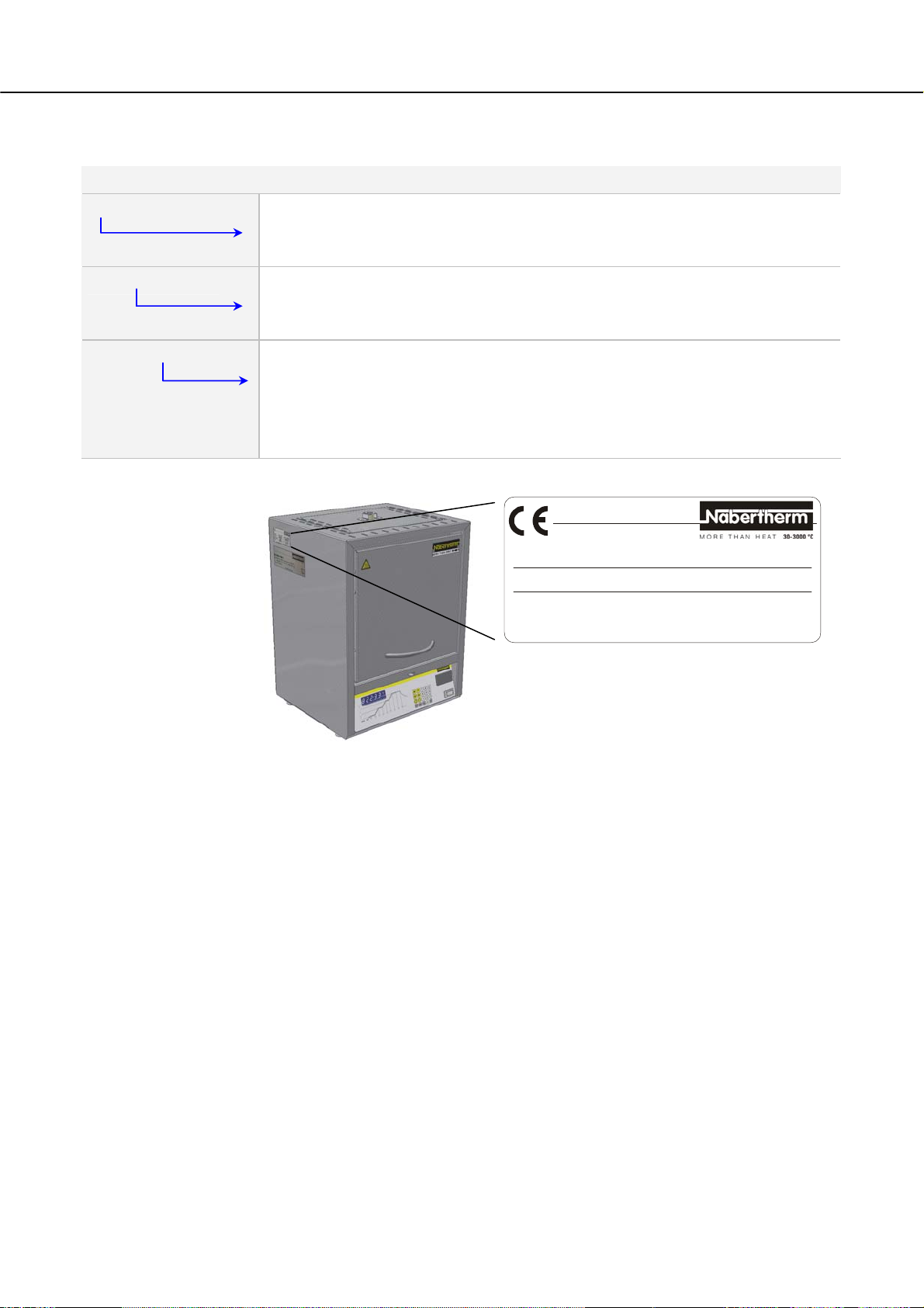
1.3 Key to the Model Names
Pos: 11 /TD/Einleitung/Produktbeschreibung/ Öfen/Entschlüssellung der Modellbezeichnung HTCT 01/14-16 @ 12\mod_1274282170968_51.doc @ 75940 @
Example Explanation
HTCT 01/16
HTCT = high-temperature furnace (tabletop model)
HTCT 01/16
01 = 1-liter furnace chamber (volume in L)
HTCT 01/16
14 = Tmax 1400 °C (2552 °F)
15 = Tmax 1500 °C (2732 °F)
16 = Tmax 1600 °C (2912 °F)
Pos: 12 /=== Seitenumbruch === @ 0\mod_1158819844943_0.doc @ 2983 @
HTCT 01/16
LC011H6SN 1600 °C 2010
220-240 V 1/N/PE~ 15.2 A 50 Hz 3.5 kW
www.nabertherm.de Made in Germany
Fig. 2: Example model designation (type plate)
SN xxxxxx
8
Page 9

Pos: 13 /TD/Einleitung/Lieferumfang/Öfen/Über schrift - Lieferumfang @ 0\mod_1167822508130_51.doc @ 5112 @ 2
1.4 Scope of Delivery
Pos: 14 /TD/Einleitung/Lieferumfang/Öfen/HTC T 01/ 14-16 - Hochtemperaturöfen - Lieferumfang @ 12\mod_1274282244951_51.doc @ 75957 @
The scope of supply includes:
System component Quantity Comment
HTCT ../.. high-temperature furnace (tabletop
1 x Nabertherm GmbH
model)
Allen key
Exhaust air pipe
1 x Nabertherm GmbH
1 x Nabertherm GmbH
Insert plate
1 x Nabertherm GmbH
T
4
A
2
5
0
V
V
A
0
4
5
2
T
H
Fuse *)
1 x *) Nabertherm GmbH
Mains power cable *)
1 x Nabertherm GmbH
Gas supply system *)
1 x Nabertherm GmbH
Tansformer *)
1 x Nabertherm GmbH
Other components depending on variant - - - See delivery documents
Pos: 15 /=== Seitenumbruch === @ 0\mod_1158819844943_0.doc @ 2983 @
Type of document Quantity Comment
Operating instructions, HTCT ../.. high-
1 x Nabertherm GmbH
temperature furnace (tabletop model)
Operating instructions, controller *) 1 x Nabertherm GmbH
Operating instructions, gas supply system *) 1 x Nabertherm GmbH
Other documents depending on variant - - -
*) = in scope of delivery depending on variant
Note
Please carefully retain all documents. During fabrication and before delivery, all the
functions of this furnace system have been tested.
9
Page 10
Pos: 16 /TD/Einleitung/Technische Daten/Öfen/ Üb er schrift - Technische Daten - mit Hinweis @ 0\mod_1167822840737_51.doc @ 5121 @ 1
2 Specifications
Pos: 17 /TD/Einleitung/Technische Daten/Öfen/ Mo de ll-Tabelle für HTCT - 01/14-16 @ 12\mod_1274282376965_51.doc @ 75974 @
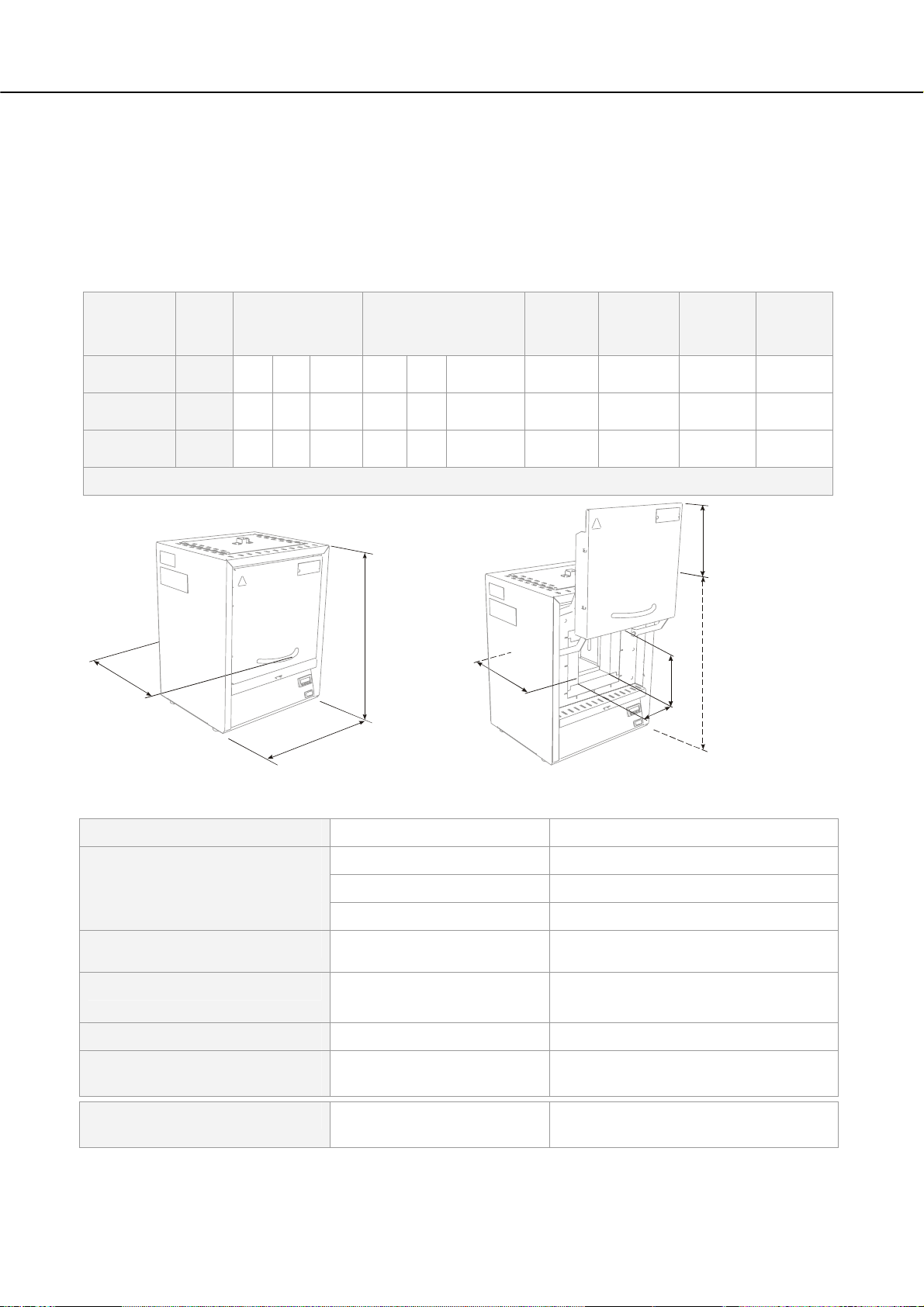
High-temperature furnace
Electrical specifications are on the type plate located on the side of the oven.
Model Tmax
°C
Dimensions,
interior in mm
w d h
Dimensions,
exterior in mm
W D H+c
Volume
in L
Output
kW
Weight
kg
Minutes
to
Tmax
HTCT 01/14 1400 110 120 120 340 300 500+185 1 max. 3.5 25 40
HTCT 01/15 1500 110 120 120 340 300 500+185 1 max. 3.5 25 50
HTCT 01/16 1600 110 120 120 340 300 500+185 1 max. 3.5 25 60
c
D
H
d
H
h
w
W
Fig. 3: Dimensions of high-temperature furnace
Pos: 18 /TD/Einleitung/Technische Daten/Öfen/ Tabe lle für HTCT 01/14-16 - Öfen - 1 @ 12\mod_1274282423230_51.doc @ 75991 @
Electrical connection
Thermal protection class
Protection class
Ambient conditions for electrical
equipment
Pos: 19 /TD/Einleitung/Technische Daten/Öfen/ Tabe lle Dauerschalldruckpegel < 80 dB(A) - 2 @ 1\mod_1170750985488_51.doc @ 8913 @
Emissions
1-phase: (1/N/PE)
Model: HTCT 01/14 – HTCT 01/16
Voltage: 220 V – 240 V
Frequency: 50 or 60 Hz
Power plug Protective contact plug
Furnaces:
Furnaces IP20
Temperature: Humidity: +5°C to + 40°C, max. 80% non-
Continuous sound pressure
level:
(with snap-in socket)
As per DIN EN 60519-2
Without safety controller: Class 0
condensing
< 80 dB(A)
10
Page 11

Pos: 20 /=== Seitenumbruch === @ 0\mod_1158819844943_0.doc @ 2983 @
Pos: 21 /TD/Einleitung/Gewährleistung_Haftu ng/ Überschrift - Gewährleistung und Haftung 1.1 @ 0\mod_1167822979492_51.doc @ 5130 @ 2
2.1 Warranty and Liability
Pos: 22 /TD/Einleitung/Gewährleistung_Haftung/ Öfen und Schaltanlagen - Gewährleistung und Haftung @ 0\mod_1157536440972_51.doc @ 1569 @
As regards warranty and liability, the normal Nabertherm warranty terms apply,
unless individual terms and conditions have been agreed. However, the following
conditions also apply:
Warranty and liability claims for personal injury or damage to property shall be excluded if
they are attributable to one or more of the following causes:
• Everyone involved in operation, installation, maintenance, or repair of the oven must
have read and understood the operating instructions. No liability will be accepted for
damage or disruptions to operation resulting from non-compliance with the operating
instructions.
• Not using the oven as intended,
• Improper installation, start-up, operation, or maintenance of the oven,
• Operation of the oven with defective safety equipment or improperly installed or non-
functioning safety and protective equipment,
• Not observing the references in the operating instructions to transportation, storage,
installation, start-up, operation, maintenance, or equipping the oven,
• Making unauthorized changes to the oven,
• Making unauthorized changes to the operating parameters,
• Making unauthorized changes to the parameterization, the settings, or the program,
• Original parts and accessories are designed especially for Nabertherm ovens. Replace
parts only with original Nabertherm parts. Otherwise the warranty will be void.
Nabertherm accepts absolutely no liability for damage caused by using parts that are
not original Nabertherm parts.
• Catastrophes due to third-party causes and force majeure.
Pos: 23 /=== Seitenumbruch === @ 0\mod_1158819844943_0.doc @ 2983 @
§
11
Page 12
Pos: 24 /TD/Sicherheit/Überschrift - Sicher heit @ 0\mod_1158843961540_51.doc @ 3103 @ 1
3 Safety
Pos: 25 /TD/Sicherheit/Überschrift - Bestimmung sge mäße Verwendung @ 0\mod_1167823503921_51.doc @ 5148 @ 2
3.1 Intended Use
Pos: 26 /TD/Sicherheit/Bestimmungsgemäße Verwendun g LHT-Hochtemperaturöfen (Tischmodell) @ 2\mod_1182347443948_51.doc @ 18724 @
Safety
This Nabertherm system was designed and manufactured after careful selection of the
harmonized standards to be observed as well as other technical specifications. It therefore
corresponds to the state of the art, ensuring the highest possible degree of safety.
Only materials with known characteristics and melting temperatures may be used. Check
the material safety data sheets if necessary.
Use of the furnace for any other purpose whatsoever such as processing
products other than those intended or handling hazardous substances or
substances posing a health hazard constitutes improper use and must be
agreed upon with Nabertherm in writing.
Whether or not the materials used in the furnace can potentially corrode or destroy
the insulation or heating elements must be ascertained.
For furnaces with over-temperature limit controllers, the cutoff temperature must be set to
prevent overheating of the material.
Modifications to system equipment must be agreed upon with
Nabertherm in writing. It is not permitted to remove, bypass, or shut down safety devices.
The installation instructions and safety guidelines must be observed. Otherwise, the furnace
will not be considered as being used as designated, and all claims against Nabertherm
GmbH will be void.
Opening the furnace when hot (temperature greater than 200/392 °C/°F) can lead to
accelerated wear of the following components: insulation, heating elements, and furnace
housing.
Operating with power sources, products, operating equipment, additives,
etc. that are subject to the Ordinance on Hazardous Substances or cause
risks to the health of operating personnel in any way is not permitted.
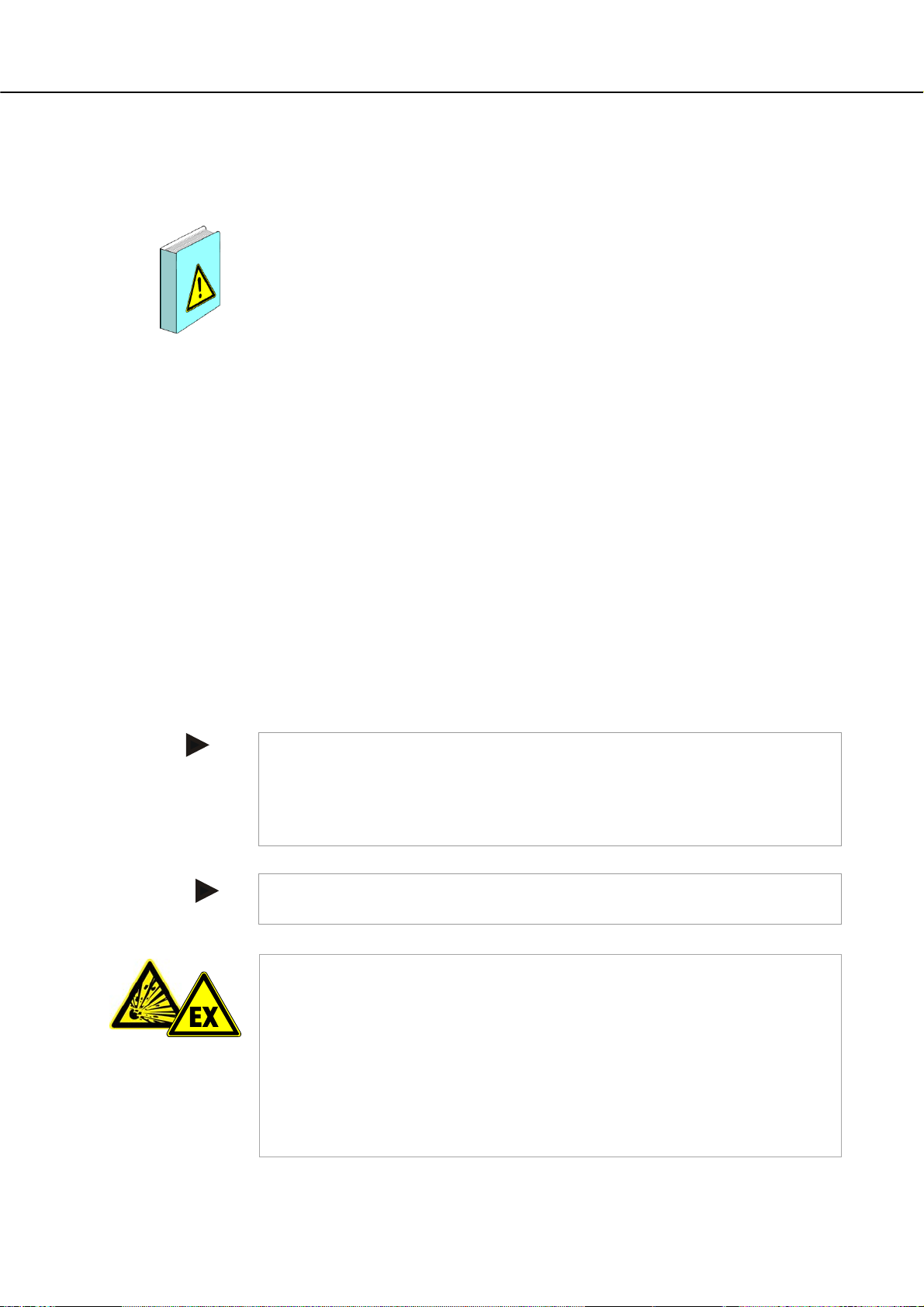
Pos: 27 /TD/Allgemeine Hinweise (für alle Anleitungen) /Hinweis - Dieser Ofen verfügt über keine Sicherheitstechnik für Prozesse, in denen zündfähige Gem @ 8\ mod _123 5038699771_51.doc @ 51483 @
- This furnace is designed for commercial use. The furnace must not be used
for heating food, animals, wood, grain, etc.
- The furnace must not be used as a workplace heater.
- Do not use the furnace to melt ice or similar materials.
- Do not use the furnace as a clothes dryer.
Note
See safety instructions in the individual sections.
Note
The oven must not be operated with explosive gases or mixtures and it must be ensured that
explosive gases or mixtures do not form during the process.
This oven has no safety technology for processes in which ignitable mixtures could form,
e.g. debinding.
If the oven is to be used for such processes, the concentration of organic gases must never
exceed 3% of the lower explosive limit (LEL) in the oven. This requirement not only
applies to normal operation, but also especially to exceptions, such as process faults (e.g.
due to the failure of a unit, etc.).
Nabertherm offers a wide range of ovens and furnaces that were especially developed for
12
Page 13
Pos: 28 /TD/Allgemeine Hinweise (für alle Anleitungen) /Hinweis - Dieses Produkt entspricht nicht der ATEX-Richtlinie und darf nicht ... @ 2\mod_11842287568 93_5 1.doc @ 19686 @
processes with ignitable gases.
Note
This product does not
comply with the ATEX Directive and may not be used in ignitable
atmospheres. It must not be operated with explosive gases or mixtures or during processes
where explosive gases or mixtures are produced.
Pos: 29 /=== Seitenumbruch === @ 0\mod_1158819844943_0.doc @ 2983 @
Pos: 30 /TD/Sicherheit/Überschrift - Anfor derungen an den Betreiber der Anlage @ 0\mod_1167823775531_51.doc @ 5157 @ 2
3.2 Requirements for the Oven Operator
Pos: 31 /TD/Sicherheit/Anforderungen an den Betreiber der Anlage - RHTH, RHTC, LHT, Rohröfen @ 2\mod_1184570280797_51.doc @ 19913 @
The set-up instructions and safety regulations must be followed, otherwise the oven will be
deemed to have been used improperly, effectively cancelling any claims against
Nabertherm GmbH.
This level of safety when operating the oven can be achieved only if all the necessary
measures have been taken. It depends on the oven operator's diligence in planning these
measures and controlling how they are carried out.
The operator must ensure that
• all harmful gases are removed from the workplace, for example by an extraction
system,
• the extraction system is switched on,
• the workplace is properly ventilated,
• the oven is operated only in a perfect operating condition and, in particular, that the
functions of the safety components are checked regularly.
• the required personal protective equipment is available for and used by the
operating, maintenance, and repair personnel.
• these operating instructions, including the supplier documentation, are kept near the
oven. These instructions must be available at all times for anyone working with or
on the oven;
• all the safety and operating instruction signs on the oven can be read properly.
Damaged or unreadable signs must be replaced immediately,
• oven personnel are informed regularly about all issues involving occupational safety
and environmental protection and are familiar with all the operating instructions,
especially those involving safety,
• a risk assessment is carried out (in Germany, covered by Section 5 of the
Occupational Safety Act) to determine any other hazards that may result from the
working conditions particular to the oven's location,
• all other instructions and safety guidelines that have been determined in a risk
assessment for the workplace are compiled in an operation manual (in Germany,
covered by Section 6 of the Ordinance Regulating the Use of Operating
Equipment).
• operating personnel still in training initially perform their work at the oven under the
supervision of an experienced person. Successful completion of the training period
must be confirmed in writing.
Pos: 32 /=== Seitenumbruch === @ 0\mod_1158819844943_0.doc @ 2983 @
Note
In Germany, the VBG and BGZ accident prevention regulations must be followed. The
accident prevention regulations applicable in the country where the oven is installed must
be followed.
13
Page 14

Pos: 33 /TD/Sicherheit/Überschrift - Anfor derungen an das Bedienpersonal @ 0\mod_1167825643423_51.doc @ 5166 @ 2
3.3 Requirements for the Operating Personnel
Pos: 34 /TD/Sicherheit/Anforderungen an das Bedienper s onal @ 0\mod_1158218663482_51.doc @ 2155 @
The oven may be operated only by persons who are trained, instructed, and authorized to do
so. These persons must know the operating instructions and act accordingly. The
authorizations of the operating personnel must be clearly defined.
Only adequately qualified and authorized persons may operate, maintain, or repair the oven.
Operating personnel are instructed regularly in all aspects of occupational safety and
environmental protection and are familiar with all the operating instructions, in particular,
safety instructions.
Only trained personnel may operate the control and safety equipment.
The operator should complete these details:
• Operator____________________________________________________
• The oven may only be transported by _____________________________
• The oven may only be installed by _____________________________
• The oven may only be commissioned by___________________________
• Initial instructions may only be given by____________________________
• Faults may only be rectified by _____________________________
• The oven may only be maintained by _____________________________
• The oven may only be cleaned by _____________________________
• The oven may only be serviced by _____________________________
• The oven may only be repaired by _____________________________
• The oven may only be shut down by _____________________________
Pos: 35 /TD/Sicherheit/Überschrift - Schutzklei du ng @ 0\mod_1167825795750_51.doc @ 5175 @ 2
3.4 Protective Clothing
Pos: 36 /TD/Sicherheit/Schutzkleidung - Hitzebes tändige Handschuhe tragen @ 9\mod_1246542013306_51.doc @ 62473 @
Wear heat-resistant gloves to protect your hands.
Pos: 37 /=== Seitenumbruch === @ 0\mod_1158819844943_0.doc @ 2983 @
Pos: 38 /TD/Sicherheit/Überschrift - Grundlegende Maßnahmen bei Normalbetrieb @ 0\mod_1167825919827_ 51.doc @ 5184 @ 2
3.5 Basic Measures During Normal Operation
Pos: 39 /TD/Sicherheit/Grundlegende Maßnahmen bei Norm al betrieb (LHT ../..-Tischmodell) @ 3\mod_1195478872113_51.doc @ 27827 @
Risks during Normal Operation!
Before switching the oven on, check and ensure that only authorized persons are in the
working area of the oven and that no one can be injured as a result of operating the oven.
Before starting production each time, check and ensure that all the safety equipment works
properly.
Before starting production each time, check the oven for obvious damage and ensure that it
is operated only in a perfect condition. Report any defects to a supervisor immediately.
Before starting production each time, remove all materials and objects that are not needed
for production from the working area.
At least once every day (see also Servicing and Maintenance) check the following:
• Check the oven for obvious external damage,
• Check that all safety equipment is working as intended (e.g. emergency stop button),
14
Page 15
• Check all hydraulic or pneumatic hoses, make sure that they are not leaking and that
they are connected properly (if applicable),
• Check all gas and oil lines, make sure that they are not leaking and that they are
connected properly (if applicable),
• Check that the fan works properly,
Pos: 40 /=== Seitenumbruch === @ 0\mod_1158819844943_0.doc @ 2983 @
Pos: 41 /TD/Sicherheit/Überschrift - Grundlegende Maßnahmen im Notfall @ 1\mod_1170943369267_51.doc @ 9093 @ 2
3.6 Basic Measures in Case of Emergency
Pos: 42 /TD/Sicherheit/Überschrift - Verhalten im No tf al l @ 1\mod_1170949904855_51.doc @ 9123 @ 3
3.6.1 What to do in an Emergency
Pos: 43 /TD/Allgemeine Hinweise (für alle Anleitungen) /Hinweis - Das Stillsetzen im Notfall ist vorgesehen durch Ziehen des Netzsteckers. @ 6\mod_1222062836 860_51.doc @ 42829 @
Note
The power plug is to be pulled out to stop the oven in case of an emergency. Therefore,
the power plug must be accessible at all times when the oven is operating so that it can be
pulled out quickly in case of an emergency.
Pos: 44 /TD/Sicherheit/Grundlegende Maßnahmen im Notf a ll - Netzstecker ziehen HTCT - Grafik @ 12\mod_1274340493221_51.doc @ 76013 @
Pos: 45 /TD/Allgemeine Hinweise (für alle Anleitungen) /Warnung - Bei unerwarteten Vorgängen im Ofen (z.B. starke Rauchentwicklung oder Geruchsbelästigung) @ 4\ mod_1205306579737_51.doc @ 34218 @
Pos: 46 /TD/Sicherheit/Sicherheitssymbole/W arnhinweise-ISO-ANSI/Warnsymbol_Gefahr - Elektrischer Schlag - Piktogramm elektr. Schla g - Hauptschalter @ 9\mod_1247472185096_51.doc @ 63063 @
Fig. 4: Pulling the power plug
Risks during Normal Operation!
Switch the oven off immediately in case of unexpected occurrences in the oven (e.g. a lot of
smoke or unusual smells). Wait until the oven has cooled naturally to room temperature.
15
Page 16
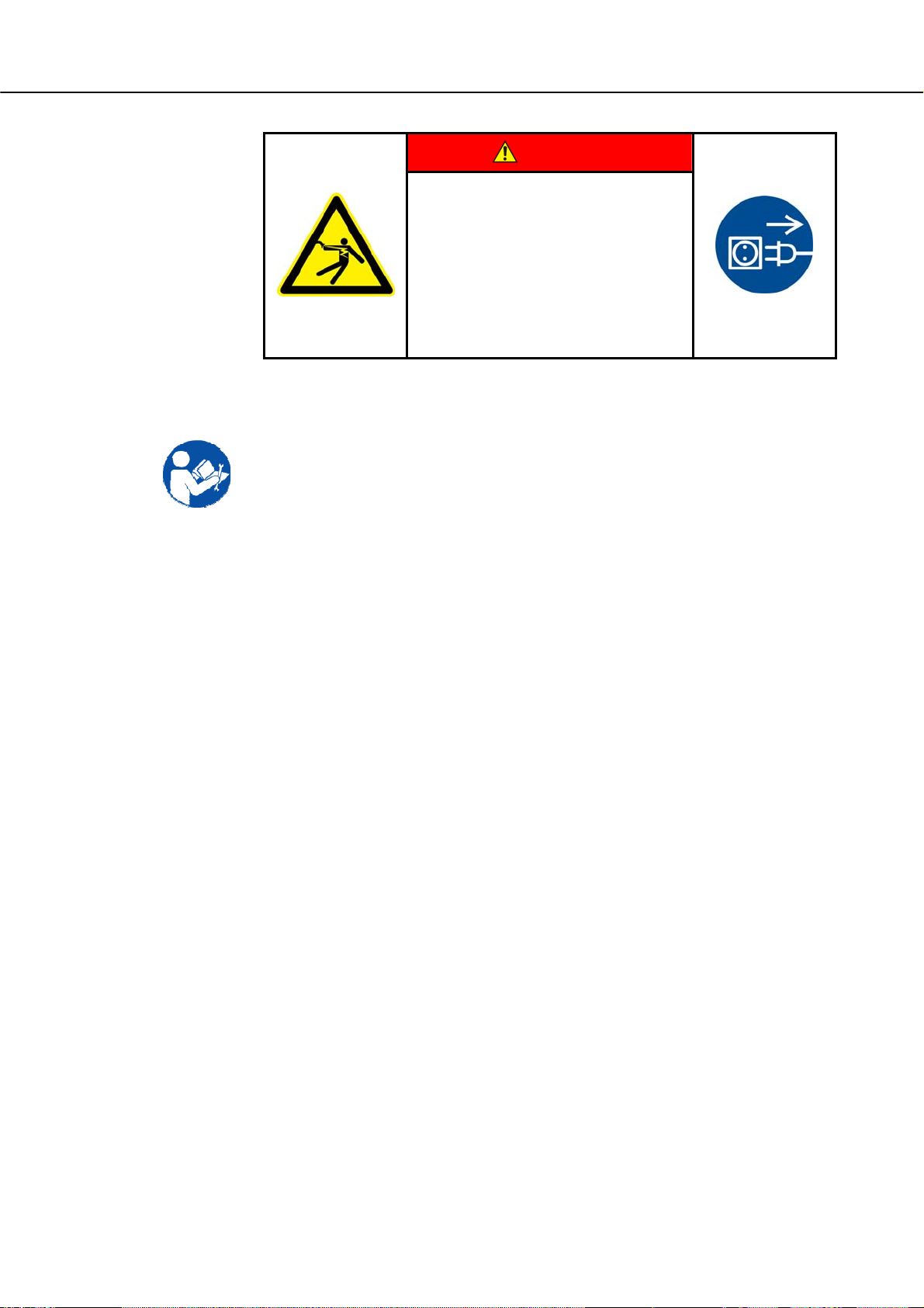
DANGER
• Danger of electric shock.
• Risk of fatal injury.
• Work on electrical
equipment may be carried out only by
qualified electricians
or by trained personnel authorized by
Nabertherm.
• Before starting work, pull out the
power plug
Pos: 47 /TD/Sicherheit/Überschrift - Grundlegende Maßnahmen bei Wartung und Instandhaltung @ 0\mod_1167 826060620_51.doc @ 5193 @ 2
3.7 Basic Measures for Servicing and Maintenance
Pos: 48 /TD/Sicherheit/Grundlegende Maßnahmen bei W artung und Instandhaltung @ 0\mod_1158222458436_51.doc @ 2188 @
Maintenance work must be performed by authorized persons following the maintenance
instructions and the accident prevention regulations. We recommend that the maintenance
and repair work be carried out by the service team of Nabertherm GmbH. Non-compliance
may cause injuries, death, or considerable damage to property.
Switch off the oven and make sure it cannot be switched on again inadvertently (lock the
main switch and secure it with a padlock), or pull out the power plug.
Clear an adequate area around the oven to facilitate the repair work.
Suspended loads are dangerous. Working beneath a suspended load is prohibited. There is a
risk of fatal injury.
Relieve the pressure on hydraulic equipment before carrying out maintenance or repair
work (if applicable).
When cleaning ovens, control cabinets, or electrical equipment housings, never spray them
with water.
When maintenance or repair work has been completed, before recommencing production
ensure the following:
• Check that loosened screw connections have been re-tightened,
• Reinstall protective equipment, screens, and filters,
• Remove all material, tools, and other equipment used for the maintenance or repair
work from the working area of the oven,
• Remove any liquids that have leaked,
• Check that all safety functions (e.g. emergency stop button) work properly,
Power cables may be replaced only with similar, approved cables.
Pos: 49 /=== Seitenumbruch === @ 0\mod_1158819844943_0.doc @ 2983 @
16
Page 17
Pos: 50 /TD/Sicherheit/Überschrift - Umweltschutz vorschriften @ 0\mod_1167826189237_51.doc @ 5202 @ 2
3.8 Environmental Regulations
Pos: 51 /TD/Sicherheit/Umweltschutzvorschr iften Schmierfette-Hydrauliköl-Kühlmittel @ 0\mod_1158223424304_51.doc @ 2199 @
All statutory duties regarding waste avoidance, proper recycling, and disposal must be
observed when work is carried out on and with the oven.
Problem materials that are no longer needed, such as lubricants or batteries, must not be
placed in normal waste disposal systems or allowed to enter the sewage system.
During installation, repair, and maintenance work, substances that are hazardous to water,
such as
• lubricating grease and oils
• hydraulic oils
• refrigerants
• solvent-based cleaning fluids must not be allowed to contaminate the soil or enter the
sewage system.
These substances must be stored, transported, collected, and disposed of in suitable
containers.
Note
The operator must ensure that national environmental regulations are observed.
Pos: 52 /TD/Sicherheit/Umweltschutzvorschr iften Elektronische Bauteile-Isolierung-Altmetall @ 4\mod_1205143314853_51.doc @ 32563 @
Pos: 53 /=== Seitenumbruch === @ 0\mod_1158819844943_0.doc @ 2983 @
When it is delivered, this oven contains no substances that make a hazardous waste
classification necessary. However, residues of process materials may accumulate in the
oven insulation during operation. These may be hazardous to health and/or the
environment.
• Dismantle the electronic components and dispose of them as electric scrap.
• Remove the insulation and dispose of it as hazardous waste (See Servicing, Cleaning,
and Maintenance with Ceramic Fiber Material)
• Dispose of the housing as scrap metal.
17
Page 18
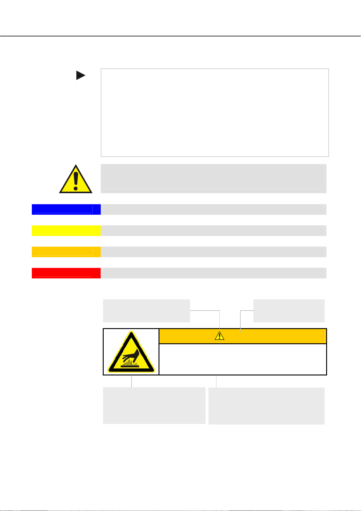
Pos: 54 /TD/Sicherheit/Sicherheitssymbole/W arnhinweise-ISO-ANSI/Erläuterung ANSI Z535.6 @ 8\mod_1243323558881_51.doc @ 57444 @ 2
3.9 Explanation of the Symbols and Warnings
Note
NOTICE
In the following operating instructions, specific warnings are given to draw attention to
residual risks that cannot be avoided when the oven is operating. These residual risks
include dangers for humans/products/ the oven, and the environment.
The symbols used in the operating instructions are especially intended to draw attention to
safety information.
The symbols used cannot replace the text of the safety information. Therefore, always read
the entire text.
Graphic symbols correspond to ISO 3864. In accordance with the American National
Standard Institute (ANSI) Z535.6 the following warning information and words are used in
this document:
The general hazard symbol, in combination with the words CAUTION, WARNING and
DANGER warns about the risk of serious injury. Observe the following information to
prevent injury or death.
Refers to a hazard that could damage or destroy the equipment.
CAUTION
WARNING
DANGER
Refers to a hazard with a minor or medium risk of injury.
Refers to a hazard that could cause death, serious or irreversible injury.
Refers to a hazard that could directly cause death, serious or irreversible injury.
Structure of the warning: All warnings are structured as follows
Hazard symbol
Indicates the risk of injury
Signal word
Classifies the danger
WARNING
• Type and source of the danger
• Consequences of non-compliance
• Action to prevent danger
Graphical symbols (optional)
according to ISO 3864:
Consequences, measures, and
prohibitions
Reference texts:
• Type and source of the danger
• Possible consequences of noncompliance
18
Page 19

Pos: 55 /TD/Sicherheit/Sicherheitssymbole/W arnhinweise-ISO-ANSI/Überschrift - Hinweissymbole in der Anleitung @ 9\mod_1247053429626_51. doc @ 62751 @
Pos: 56 /TD/Sicherheit/Sicherheitssymbole/W arnhinweise-ISO-ANSI/Hinweis - Unter diesem Symbol erhalten Sie Anweisungshinweise und ... @ 9\ mod_1247053932311_51.doc @ 62785 @
Pos: 57 /TD/Sicherheit/Sicherheitssymbole/W arnhinweise-ISO-ANSI/Piktogramm in der Anleitung - Gebot - Gebotszeichen - Wichtige Gebote sind zu befol gen @ 9\mod_1247056175982_51.doc @ 62853 @
Pos: 58 /TD/Sicherheit/Sicherheitssymbole/W arnhinweise-ISO-ANSI/Piktogramm in der Anleitung - Gebot - Wichtige Information für den Bediener @ 9\mod_ 1247 053200729_51.doc @ 62717 @
Pos: 59 /TD/Sicherheit/Sicherheitssymbole/W arnhinweise-ISO-ANSI/Piktogramm in der Anleitung - Gebot - Wichtige Information für das Wartungsper so nal @ 9\mod_1247053206042_51.doc @ 62734 @
Pos: 60 /TD/Sicherheit/Sicherheitssymbole/W arnhinweise-ISO-ANSI/Piktogramm in der Anleitung - Gebot - Netzstecker ziehen @ 9\mod_1247055471526_51. doc @ 62836 @
or
Hazard symbol
Indicates the risk of injury
Signal word
Classifies the danger
DANGER
• Type and source of the danger
• Consequences of non-compliance
• Action to prevent danger
Graphical symbols (optional)
according to ISO 3864:
Consequences, measures, and
prohibitions
Graphical symbols
(optional) according to ISO
3864:
Instructions or prohibitions
Reference texts:
• Type and source of the danger
• Possible consequences of noncompliance
• Measures/prohibitions
Information Symbols in the Instructions:
Note
Below this symbol you will find instructions and particularly useful information.
Rule - Rule Sign
This symbol draws attention to important rules that must be followed. Rule signs protect
people against injury and show what is to be done in certain situations.
Rule - Important Information for Operators
This symbol draws the operator's attention to important information and operating
instructions that must be followed.
Rule - Important Information for Maintenance Personnel
This symbol draws the maintenance personnel's attention to important operating and
maintenance instructions (service) that must be followed.
Rule - Pull Out the Power Plug
This symbol tells the operator to pull out the power plug.
Pos: 61 /TD/Sicherheit/Sicherheitssymbole/W arnhinweise-ISO-ANSI/Piktogramm in der Anleitung - Gebot - Anheben mit mehreren Personen @ 9\mod_12470630 580 02_51.doc @ 62938 @
Pos: 62 /TD/Sicherheit/Sicherheitssymbole/W arnhinweise-ISO-ANSI/Piktogramm in der Anleitung - Warnung - Heiße Oberfläche - Oberfläche nicht ber ühr en @ 9\mod_1247054774780_51.doc @ 62802 @
Pos: 63 /TD/Sicherheit/Sicherheitssymbole/W arnhinweise-ISO-ANSI/Piktogramm in der Anleitung - Warnung - elektrischer Schlag - zur Vermeidung Anwei sung folgen @ 9\mod_1247055093892_51.doc @ 62819 @
Rule - Lift only with Several People
This symbol draws the personnel's attention to the fact that this device may only be lifted
and moved to its final destination by several people.
Warning - Hot Surface, Do Not Touch
This symbol warns the operator that the surface is hot and should not be touched.
19
Page 20

Pos: 64 /TD/Sicherheit/Sicherheitssymbole/W arnhinweise-ISO-ANSI/Piktogramm in der Anleitung - Warnung - Umkippen des Gerätes @ 9\mod_12470591983 72_5 1.doc @ 62870 @
Pos: 65 /TD/Sicherheit/Sicherheitssymbole/W arnhinweise-ISO-ANSI/Piktogramm in der Anleitung - Warnung - Schwebende Lasten @ 9\mod_1251450500309_51. doc @ 65454 @
Pos: 66 /TD/Sicherheit/Sicherheitssymbole/W arnhinweise-ISO-ANSI/Piktogramm in der Anleitung - Warnung - Heben schwerer Lasten @ 9\mod_1247059891358_ 51.doc @ 62887 @
Pos: 67 /TD/Sicherheit/Sicherheitssymbole/W arnhinweise-ISO-ANSI/Piktogramm in der Anleitung - Warnung - Umweltgefährdung @ 9\mod_1247060443419_ 51.doc @ 62904 @
Pos: 68 /TD/Sicherheit/Sicherheitssymbole/W arnhinweise-ISO-ANSI/Piktogramm in der Anleitung - Warnung - Brandgefahr @ 9\mod_1251445272822_51.d oc @ 65437 @
Pos: 69 /TD/Sicherheit/Sicherheitssymbole/W arnhinweise-ISO-ANSI/Piktogramm in der Anleitung - Warnung - Explosionsgefährliche Stoffe @ 9\ mod_1 2470 61148859_51.doc @ 62921 @
Warning - Danger of Electric Shock
This symbol warns the operator that there is a risk of an electric shock if the following
warnings are not heeded.
Warning – Risk of Device Toppling Over
This symbol tells the operator that there is a risk of the device toppling over if the following
warnings are not heeded.
Warning – Suspended Load
This symbol warns the operator of potential dangers of suspended loads. Working below a
suspended load is strictly forbidden. Ignoring this can lead to fatal injury.
Warning – Danger if Heavy Loads Are Lifted
This symbol warns the operator of the potential dangers of lifting heavy loads. Ignoring this
can lead to injury.
Warning – Risk to the Environment
This symbol warns the operator of the risk to the environment if the following information
is not heeded. The operator must ensure that national environmental regulations are
observed.
Warning - Fire Danger
This symbol warns operators of the danger of fire if the following information is not
followed.
Warning – Risk of Explosive Substances or
Explosive Atmosphere
These symbols warn the operator of explosive substances or an explosive atmosphere
Pos: 70 /TD/Sicherheit/Sicherheitssymbole/W arnhinweise-ISO-ANSI/Piktogramm in der Anleitung - Gefahr - nicht mit Wasser überschütten @ 9\mod_12 4782 6410886_51.doc @ 63819 @
Pos: 71 /TD/Sicherheit/Sicherheitssymbole/W arnhinweise-ISO-ANSI/Überschrift - Warnhinweissymbole an der Anlage @ 9\mod_1247053700273_51.d oc @ 62768 @
Pos: 72 /TD/Sicherheit/Sicherheitssymbole/W arnhinweise-ISO-ANSI/Piktogramm an der Anlage - Warnung - Gefahr vor heißer Oberfläche und Verbrennung @ 9\mod_1 247052957145_51.doc @ 62700 @
Pos: 73 /TD/Sicherheit/Sicherheitssymbole/W arnhinweise-ISO-ANSI/Piktogramm an der Anlage - Warnung - Gefahren durch elektrischen Strom @ 9\mod_12470526 39824_51.doc @ 62683 @
Pos: 74 /=== Seitenumbruch === @ 0\mod_1158819844943_0.doc @ 2983 @
Prohibited - Important Information for Operators
This symbol warns the operator that water or cleaning products must NOT be poured over
the objects. A high-pressure cleaning device must also not be used.
Warning Signs on the Oven:
Warning - Hot Surface, Danger of Burning – Do Not Touch
You may not always realize that surfaces, such as oven components, oven walls, doors and
materials, and even liquids are hot. Do not touch the surface.
Warning - Danger of Electric Shock!
Warning, dangerous electric voltage
20
Page 21

Pos: 75 /TD/Sicherheit/Überschrift - Allgemeine Gefahren an der Anlage @ 0\mod_1168596796288_51.doc @ 6014 @ 2
3.10 General Risks with the Oven
Pos: 76 /TD/Sicherheit/Allgemeine Gefahren (Ver br ennung, Quetschen, Strom) - Laboröfen @ 2\mod_1184666023022_51.doc @ 19974 @
Warning! General hazards!
- Risk of burning on the furnace housing and on the tube
- The door handle/grip can become very hot during operation; wear gloves.
- Risk of crushing on moving parts (door hinge, rotary tube drive,
lifting table, etc.)
- The switchgear cabinet (if present) and the terminal boxes on the system contain
dangerous electrical voltages.
- Do not insert any objects into the openings on the furnace housing, exhaust air holes, or
cooling slots on the
Pos: 77 /TD/Allgemeine Hinweise (für alle Anleitungen) /Warnung - Es dürfen keine Gegenstände auf den/der Ofen/Schaltanlage abgelegt/abgestellt werden... @ 4\mod_1203924555465_51. doc @ 31568 @
switchgear or furnace (if present). This poses a risk of electric shock.
Warning! General hazards!
No objects may be placed or set down on the furnace or switchgear. Doing so creates a fire
or explosion hazard.
Pos: 78 /=== Seitenumbruch === @ 0\mod_1158819844943_0.doc @ 2983 @
Pos: 79 /TD/Transport_Montage_Inbetriebnahme/E r stinbetriebnahme/Überschrift - Transport, Montage und Erstinbetriebnahme @ 0\mod_115884422 7416 _51.doc @ 3112 @ 1
4 Transportation, Installation, and Commissioning
Pos: 80 /TD/Transport_Montage_Inbetriebnahme/Er stinbetriebnahme/Überschrift - Anlieferung @ 0\mod_1167826534889_51.doc @ 5220 @ 2
4.1 Delivery
Pos: 81 /TD/Transport_Montage_Inbetriebnahme/Er stinbetriebnahme/Anlieferung - (Hinweise allgemein) @ 0\mod_1158233508887_51.doc @ 2223 @
Check that Everything is Complete
Compare the delivered items with the delivery note and the purchase order documents.
Immediately notify the carrier and Nabertherm GmbH of any missing or damaged parts, as
complaints at a later date cannot be acknowledged.
Danger of Injury
When the oven is being lifted, parts of the oven or the oven itself could topple over, slip, or
fall. Before the oven is lifted, make sure no one is in the working area. Wear safety
footwear and a hard hat.
Safety Instructions
• Forklifts must be operated only by authorized personnel. The operator bears sole
responsibility for safe operation and the load.
• When the oven is being lifted, make sure that the ends of the forks or the load do not
catch on neighboring goods. Use a crane to move tall parts, such as control cabinets.
• Use only lifting equipment with sufficient load-bearing capacity.
21
Page 22

• Lifting gear must be attached only to positions that have been designated for this
purpose.
• Attachments, piping, or cable conduits must never be used to affix lifting gear.
• Unpackaged parts should only be lifted with ropes or straps.
• Attach transportation equipment only to positions intended for this purpose.
• Lifting and securing equipment must conform to the provisions contained in accident
prevention regulations.
• Consider the weight of the oven when choosing lifting and securing equipment. (see
Specifications)
• Stainless steel parts (including mounting elements) must always be kept separate from
unalloyed steel parts.
• Do not remove corrosion protection until immediately prior to assembly.
Risks during Normal Operation!
Suspended loads are dangerous. Working beneath a suspended load is prohibited. There is a
risk of fatal injury.
Note
Safety and accident prevention guidelines applicable for forklift trucks must be followed.
Pos: 82 /=== Seitenumbruch === @ 0\mod_1158819844943_0.doc @ 2983 @
Pos: 83 /TD/Transport_Montage_Inbetriebnahme/Er stinbetriebnahme/Anlieferung von Öfen mit einem Hubwagen @ 2\mod_1184672460200_51.doc @ 20000 @
Transportation with a Pallet Truck
Observe the maximum permitted capacity of the pallet truck.
1. Our ovens are delivered ex works on wooden frames to facilitate unloading.
Transport the oven in its original packaging and with suitable equipment to prevent
any damage. Remove the packaging only when the oven is in its final location.
When transporting the oven, make sure it is secured against sliding, toppling over,
and damage. The oven should be transported and installed by at least two persons.
Do not store the oven in damp rooms or outdoors.
2. Push the pallet truck underneath the transportation frame. Make sure that the pallet
truck is completely beneath the frame. Pay attention to neighboring goods.
Fig. 5: Pallet truck is pushed completely beneath the transportation frame
3. Lift the oven carefully and pay attention to its center of gravity. When the oven is
being lifted, make sure that the ends of the forks or the load do not catch on
neighboring goods.
4. Make sure that the oven is balanced safely; if not, attach securing equipment. Push
the oven carefully, slowly and with the pallet truck at its lowest position. Do not
transport the oven on inclines.
22
Page 23

Pos: 84 /TD/Sicherheit/Sicherheitssymbole/W arnhinweise-ISO-ANSI/Warnsymbol_Vorsicht - Rutschen/Kippen des Gerätes - Piktogramm Kippen/ Heben/Anheben @ 9\mod_1247064081950_51.doc @ 62955 @
Pos: 85 /=== Seitenumbruch === @ 0\mod_1158819844943_0.doc @ 2983 @
Pos: 86 /TD/Transport_Montage_Inbetriebnahme/ Er stinbetriebnahme/Legende für Packstücke z.B. zerbrechlich @ 1\mod_1173776713307_51.doc @ 10746 @
5. Carefully lower the oven at its final position. Pay attention to neighboring goods.
Try not to set it down too abruptly.
CAUTION
• Device may slip or topple over.
• Damage to the device.
• Risk of injury from lifting
heavy loads.
• Transport device only in original
packaging.
• Several people must carry the device.
Symbols:
The international standard symbols for handling packaging are defined in ISO R/780
(International Organization for Standardization) and in DIN 55 402 (German Institute for
Standardization).
Description Symbol Explanation
Pos: 87 /=== Seitenumbruch === @ 0\mod_1158819844943_0.doc @ 2983 @
Fragile
This side up
Keep dry
Sling here
This symbol is to be attached to fragile goods. Goods
marked like this are to be handled carefully and must not be
thrown or tied up.
The freight must be transported, transshipped, and stored in
such a way that the arrows point upward. The freight must
not be rolled, folded, or stored on edge. However, the
package does not have to be packed on top of other freight.
Products with this symbol must be protected against high air
moisture, hence, they must be stored under cover. If
particularly heavy or bulky packages cannot be stored in
halls or sheds, they must be covered carefully with a
tarpaulin or similar.
The symbol shows only where the sling should be attached,
not the method of slinging. If the symbols are at an equal
distance from the middle or center of gravity of the package,
the package hangs straight if the slings are the same length.
If this is not the case, the sling on one side has to be
shortened.
23
Page 24

Pos: 88 /TD/Transport_Montage_Inbetriebnahme/E r stinbetriebnahme/Überschrift - Auspacken @ 2\mod_1184739517985_51.doc @ 20013 @ 2
4.2 Unpacking
Pos: 89 /TD/Allgemeine Hinweise (für alle Anleitungen) /Hinweis - Allgemeiner Hinweis zur Verpackung (z.B. Laboröfen) @ 3\mod_1192437185846_51.doc @ 23509 @
Pos: 90 /TD/Transport_Montage_Inbetriebnahme/E r stinbetriebnahme/Auspacken Laborofen - LHT-Tischmodell , R, RT - Teil 1 @ 2\mod_1184739616497_51.doc @ 20026 @
Wear protective
gloves
Note
The oven packaging prevents damage during transportation. Make sure that you remove all
packaging material (also inside the oven chamber). Keep the packaging and transportation
securing equipment in case it is needed for future transportation or storage.
At least two people are needed to carry/transport the oven, more for larger ovens.
Pos: 91 /TD/Transport_Montage_Inbetriebnahme/E r stinbetriebnahme/Auspacken Hochtemperaturofen - HTCT 01/14-16-Tischmodell - Teil 2 @ 12\mod_12819 42490665_51.doc @ 96845 @
Pos: 92 /TD/Transport_Montage_Inbetriebnahme/E r stinbetriebnahme/Auspacken-Tragen Laborofen - LHT-Tischmodell - Teil 3 @ 3\mod_1192436920381 _51. doc @ 23483 @
1
2
1. Check the transportation packaging for possible damage.
2. Remove tensioning straps from the transportation packaging.
3. Slacken screws and remove wooden casing from the covering box (if available).
4
5
6
4. Carefully lift the cardboard box and remove it from the pallet.
5. Remove the foam insert in the box. The box contains a packaging unit for
accessories (Example: exhaust air tube, insert plate, power cable). Compare the
delivered items with the delivery note and the order documents, see "Delivery".
6. Carefully lift the furnace out of the packaging unit.
3
24
Page 25

7. To carry, grip furnace from below at the sides and make sure you have a firm grip.
8. For furnaces weighing more than 25 kg, transport work must be carried out by at
least 2 people. If transport straps are used, they must be attached crosswise only.
Ensure that they are secure.
Note
In Germany, the general accident protection guidelines of VBG or BGZ must be observed.
The national accident prevention regulations of the country of operation apply.
Note
Save the packaging for possible shipping or for storing the furnace.
Pos: 93 /=== Seitenumbruch === @ 0\mod_1158819844943_0.doc @ 2983 @
Pos: 94 /TD/Transport_Montage_Inbetriebnahme/E r stinbetriebnahme/Überschrift - Transportsicherung/Verpackung @ 0\mod_1167826775847_ 51.doc @ 5229 @ 2
4.3 Transportation Securing Equipment/Packaging
Pos: 95 /TD/Transport_Montage_Inbetriebnahme/E r stinbetriebnahme/Verpackung - Allgemeine Hinweise zur Verpackung - spezielle Transportsicher ung vorhanden @ 12\mod_1281944551971_51.doc @ 96867 @
The oven packaging prevents damage during transportation. Make sure that you remove all
packaging material (also inside the oven chamber). All packaging material can be recycled.
The packaging was designed so that no special description is necessary.
Pos: 96 /TD/Transport_Montage_Inbetriebnahme/E r stinbetriebnahme/Verpackung - Allgemeine Hinweise zur Verpackung - spezielle Transportsicher ung für HTCT-Öfen @ 12\mod_1274343084196_51.doc @ 76081 @
The furnace has been equipped with protective edging to protect it against damage during
transportation. This edging must be removed before you operate the furnace.
Fig. 6: Unscrew the screws from the lid using the tool that is provided.
25
Page 26

Fig. 7: Lift the lid and remove the foam.
Fig. 8: Fix the lid back in place using the screws that you previously unscrewed. Make sure
that you place a tooth lock washer between the screw and the lid. This position is marked
by a ground sticker on the housing/lid. Loosen the protective metal sheet of the exhaust air
tube from the lid. Carefully slide the exhaust air tube into the intended opening. The top of
the exhaust air tube must sit on the lid.
Pos: 97 /=== Seitenumbruch === @ 0\mod_1158819844943_0.doc @ 2983 @
26
Fig. 9: Assemble the protective metal sheet of the exhaust air tube with the screws that you
previously unscrewed.
Open the lift door and remove the protective foil from the furnace chamber.
Note
Keep the transport protection in case you have to ship the furnace. To prevent damage to
the heating elements during any future transportation, the furnace must be prepared as
shown in picture above.
Page 27

Pos: 98 /TD/Transport_Montage_Inbetriebnahme/E r stinbetriebnahme/Überschrift - Bauliche- und Anschlussvoraussetzungen @ 0\mod_11678268909 43_51.doc @ 5238 @ 2
4.4 Constructional and Connection Requirements
Pos: 99 /TD/Transport_Montage_Inbetriebnahme/E r stinbetriebnahme/Überschrift - Aufstellung (Standort des Ofens) @ 2\mod_1184848718972_51.doc @ 20166 @ 3
4.4.1 Installation (Oven Location)
Pos: 100 /TD/Transport_Montage_Inbetriebnahme/Er stinbetriebnahme/Standort eines LHT-Ofens @ 2\mod_1184852454302_51.doc @ 20179 @
When setting up the furnace, the following safety instructions must be followed:
• The furnace must be installed in a dry room in accordance with the safety instructions.
• The table/supporting surface must be flat to enable the furnace to be installed straight.
The furnace must be placed on a noncombustible base (stone, metal, etc.).
• The carrying capacity of the table must be designed to bear the weight of the furnace
incl. accessories.
• The floor covering must be made of nonflammable material so that hot material
falling out of the furnace will not cause the floor covering to ignite.
Despite good insulation, the furnace radiates heat from its external surfaces. If necessary,
this heat must be conducted away (a ventilation engineer must be consulted if required).
In addition, the furnace must be positioned a minimum safety distance (S) of 0.5 m on each
side and 1 m at the top away from combustible materials. In individual cases, more space
must be chosen in order to match the local conditions. The minimum distance away from
noncombustible materials may be reduced to 0.2 m at the sides.
Should gases or vapors escape from the charge, then sufficient air supply and ventilation at
the installation location or an appropriate exhaust gas line must be provided.
A suitable exhaust for the burner exhaust must be provided by the customer.
Pos: 101 /TD/Sicherheit/Sicherheitssymbole/W arnhinweise-ISO-ANSI/Warnsymbol_Gefahr - Brandgefahr - Piktogramm Brandgefahr @ 9\mod_1247148035 738_51.doc @ 63010 @
S
S
S
S
Noncombustible base
Fig. 10: Installation of an high-temperature furnace
• Fire- danger to health.
• Risk of fatal injury.
• Adequate ventilation must be ensured at the
installation location to conduct waste heat and any
exhaust gases away.
DANGER
Pos: 102 /TD/Allgemeine Hinweise (für alle Anleitungen) /Hinweis - Vor Inbetriebnahme des Ofens sollte dieser 24 Stunden am Aufstellungsort akklimatisier t .. @ 3\mod_1195568014336_51.doc @ 27871 @
Pos: 103 /=== Seitenumbruch === @ 0\mod_1158819844943_0. doc @ 2983 @
Pos: 104 /TD/Transport_Montage_Inbetriebnahme/E r stinbetriebnahme/Überschrift - Montage, Installation und Anschluss @ 0\mod_1167827976269_ 51.doc @ 5292 @ 2
Note
Before starting the oven for the first time, allow it to acclimatize at its installation location
for 24 hours.
27
Page 28

4.5 Assembly, Installation, and Connection
Pos: 105 /TD/Transport_Montage_Inbetriebnahme/Er stinbetriebnahme/Überschrift - Abgasführung @ 0\mod_1167828513042_51.doc @ 5310 @ 3
4.5.1 Waste Gas System
Pos: 106 /TD/Transport_Montage_Inbetriebnahme/Er stinbetriebnahme/Abgasführung beim LHT-Ofen @ 2\mod_1184931910984_51.doc @ 20223 @
We recommend that an exhaust air pipe be connected to the furnace and that the exhaust
gases be conducted away accordingly.
A commercially available metal exhaust gas pipe with NW80 to NW120 may be used as a
flue. It must be routed in constantly ascending form and must be secured to the wall or
ceiling.
Position the pipe centrally above the furnace's flue outlet. The exhaust gas pipe's connection
to the exhaust air pipe must not be airtight, as no bypass effect is otherwise achieved. This
is necessary to prevent an excessive amount of fresh air from being sucked through the
furnace.
Flue
Pos: 107 /=== Seitenumbruch === @ 0\mod_1158819844943_0. doc @ 2983 @
Exhaust air pipe
Fig. 11: Assembly of a flue (example)
Note
The exhaust gases can only be conducted away if the room is ventilated via a corresponding
air inlet.
Note
The exhaust gas pipe necessitates roofing and bricklaying work on the part of the customer.
The size and variant of the exhaust gas pipe should be determined by a ventilation engineer.
The national regulations of the relevant country apply.
28
Page 29

Pos: 108 /TD/Transport_Montage_Inbetriebnahme/E r stinbetriebnahme/Überschrift - 1.1.1 Anschluss an das Elektronetz @ 0\mod_1168599727688_51. doc @ 6050 @ 3
4.5.2 Connecting the Oven to the Power Supply
Pos: 109 /TD/Transport_Montage_Inbetriebnahme/E r stinbetriebnahme/Anschluss an das Elektronetz - HTC 01/15 - Renishaw @ 10\mod_1253871914414_51.doc @ 66303 @
On the building side, the required services must be provided, i.e. the carrying capacity of
the installation surface, provision of power (electricity), etc.
− The furnace must be installed in accordance with its intended use. The power
connection values must correspond to the values on the furnace type plate.
− The power socket must be located close to the furnace and must be easily
accessible. The safety requirements are not met if the furnace is not connected to a
socket with grounding contact.
− On use of an extension cable or a multipoint socket, the maximum electrical rating
must not be exceeded. Do not use the furnace with an extension cable if you are
uncertain whether grounding is guaranteed.
− The power cable must not be damaged. Do not place any objects on the power
cable. Route the cable so that nobody can tread on or stumble over it.
− A damaged power cable must be replaced immediately.
− Ensure that the furnace's connection cable is routed so that it is protected.
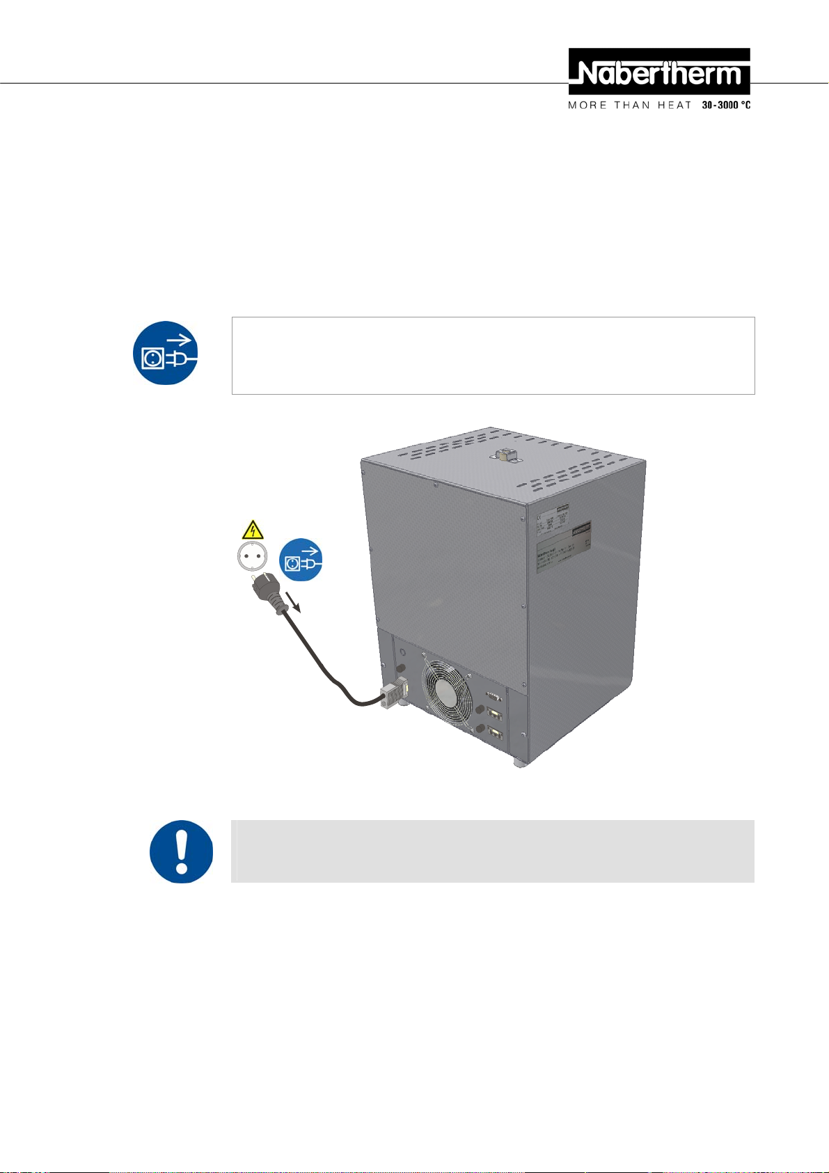
Note
Before connecting the voltage supply, make sure that the power switch is in the "Off" or
"0" position.
Type plate
2.
1.
klick
Fig. 12: Illustrated power cable enclosed in the scope of delivery
1. First connect the enclosed power cable to the intended mains power connector on the
furnace.
2. Now connect the enclosed power cable to the power connection. Only use a socket
with grounding contact to supply power.
29
Page 30

k
Pos: 110 /TD/Allgemeine Hinweise (für alle Anleitungen) /Hinweis - Verdrahtung und Elektrische Anschlüsse entnehmen Sie dem beiliegendem Schaltplan. @ 5\mod_ 1219 923893347_51.doc @ 41881 @
Pos: 111 /TD/Sicherheit/Sicherheitssymbole/W arnhinweise-ISO-ANSI/Warnsymbol_Achtung - falsche Netzspannung - Piktogramm Gebotszeic hen @ 9\mod_1247475231381_51.doc @ 63131 @
2.
1.
Abb. 13: Reconnect the power cable
Note
For wiring and electrical connections, see the attached circuit diagram. The electrical
equipment of the machine can also be seen in the circuit diagram.
NOTICE
• Danger from incorrect voltage
• Damage to the oven.
• Check voltage before connecting and
commissioning the oven.
• Compare the voltage with the details
on the type plate.
klic
Pos: 112 /TD/Transport_Montage_Inbetriebnahme/E r stinbetriebnahme/Überschrift - Aufstellung/Anschluss bei Verwendung eines Trafos @ 12\ mod_1282201241263_51.doc @ 97045 @ 3
4.5.3 Installation/Connection if a Transformer is Used
Pos: 113 /TD/Transport_Montage_Inbetriebnahme/E r stinbetriebnahme/Aufstellung/Anschluss bei Verwendung eines Trafos - HTCT 01/14-15 - Text @ 12\ mo d_12 82200352345_51.doc @ 97023 @
When you are installing a transformer, these safety instructions must be followed:
• The transformer is intended for use only with the model of furnace that is
delivered (see delivery note). If the transformer is used for any other purpose,
this is deemed to be inappropriate use.
• Check the device for damage regularly and before using it for the first time. If it is
damaged (cable, plug or housing), it must not be used. Power cables may be replaced
only with similar, approved cables.
• Operate only in dry, clean rooms at maximum 40 °C (104 °F).
• The bench/surface must be level to permit the transformer and the furnace to stand
upright. Place the transformer on a non-flammable surface (stone, metal, etc.).
• For the surrounding safety distance, see "Installation (Oven Location)".
• The load-bearing capacity of the bench must be suitable to take the weight of the
transformer/furnace plus accessories.
• Isolate the device from the power supply when it is being cleaned or maintained. Do
not open the device while it is operating.
Pos: 114 /TD/Transport_Montage_Inbetriebnahme/E r stinbetriebnahme/Aufstellung/Anschluss bei Verwendung eines Trafos - HTCT 01/14-15 - Techni sc he Daten @ 12\mod_1282222718151_51.doc @ 97089 @
30
Page 31

Pos: 115 /TD/Transport_Montage_Inbetriebnahme/E r stinbetriebnahme/Aufstellung/Anschluss bei Verwendung eines Trafos - HTCT 01/14-15 - Text- Graf ik @ 12\mod_1282222674169_51.doc @ 97067 @
Technical Specification for
Input Output
Transformer
Voltage 200 V – 208 V ~ AC 230 V ~ AC
Frequency 50 or 60 Hz 50 or 60 Hz
Max. output 3.5 kW 3.5 kW
Power plug Country-specific
Standards
EN 61558-1, Protection type I / IP 20
UL + CSA E300981
Dimensions in mm 120 x 140 x 145 (W x D x H)
The transformer is packaged carefully to prevent damage during transportation. Make sure
that you remove all the packaging material. Then carefully place the furnace
transformer housing
B
(see figure below).
Connect the furnace and the transformer with the power cable that is supplied
A
on to the
1
(cable
with snap-in coupling). Connect the power cable from the transformer to the power supply.
2
. Use only a grounded socket.
Pos: 116 /TD/Sicherheit/Sicherheitssymbole/W arnhinweise-ISO-ANSI/Warnsymbol_Gefahr - Brandgefahr - Piktogramm Brandgefahr @ 9\mod_1247148035 738_51.doc @ 63010 @
Pos: 117 /=== Seitenumbruch === @ 0\mod_1158819844943_0. doc @ 2983 @
A
B
Fig. 14: Installing/connecting a transformer
• Fire- danger to health.
• Risk of fatal injury.
• Adequate ventilation must be ensured at the
installation location to conduct waste heat and any
exhaust gases away.
2
1
DANGER
31
Page 32

Pos: 118 /TD/Transport_Montage_Inbetriebnahme/Er stinbetriebnahme/Überschrift - Einlegen der Bodenplatte LHT-Ofen @ 2\mod_1185287183100_51. doc @ 20422 @ 3
4.5.4 Insertion of the Base Plate
Pos: 119 /TD/Transport_Montage_Inbetriebnahme/Er stinbetriebnahme/Einlegen der Einlegeplatte (Bodenplatte) LHT/HTC/HTCT-Öfen @ 2\mod_1185287 451644_51.doc @ 20435 @
Fig. 15: Inserting the ceramic insert plate
Swivel the furnace lift-door carefully away upwards. Carefully place the ceramic insert
plate/s (quantity of insert plates dependent on furnace model) centrally on the base of the
furnace. When inserting the ceramic insert plate/s, ensure that the door collar and the
heating elements are not damaged. Under all circumstances, avoid coming into contact with
the heating elements when inserting the insert plate/s; this may lead to the immediate
destruction of the heating elements.
The base of the furnace is manufactured from high-quality, fireproof material which is
extremely sensitive to impact. The ceramic insert plate has the task of protecting the base of
the furnace. Damaged insert plate/s must be immediately replaced with new ones (see
chapter entitled "Replacement/Wearing Parts").
The furnace must not be commissioned without the insert plate.
If possible, the load must be positioned centrally in the working chamber on the ceramic
insert plate. This guarantees even heating.
After loading, the furnace lift-door must be closed carefully.
Pos: 120 /=== Seitenumbruch === @ 0\mod_1158819844943_0. doc @ 2983 @
32
Note
It must be ensured that the load on the furnace base does not exceed 2 kg.
Page 33

Pos: 121 /TD/Transport_Montage_Inbetriebnahme/Er stinbetriebnahme/Überschrift - Erstinbetriebnahme @ 0\mod_1167828977720_51.doc @ 5337 @ 2
4.6 Commissioning
Pos: 122 /TD/Transport_Montage_Inbetriebnahme/Er stinbetriebnahme/Erstinbetriebnahme LHT02,04,08 Öfen - 1 @ 2\mod_1186641509092_51.doc @ 20833 @
The oven may be put into operation only by qualified persons and in compliance with the
safety instructions.
Read the section on "Safety". When the oven is put into operation, the following safety
information must also be observed to prevent serious injury, damage to the oven, and
damage to other property.
Make sure that the instructions and information in the controller instructions are observed
and followed.
The oven may be used only for its intended purpose.
Ensure that only authorized persons remain in the working area of the oven and that no
other persons are put at risk when the oven is put into operation.
Before starting the oven for the first time, make sure that all tools, foreign parts, and
transportation securing equipment have been removed.
Activate all safety equipment (power switch, emergency stop button if applicable) before
putting the oven into operation.
Incorrectly wired connections may destroy electric/electronic components.
Observe the special protective measures (e.g. grounding, …) for components that are at
risk.
Faulty connections can cause the oven to start unexpectedly.
Before you switch on the oven, make sure that you know what to do in case of faults or
emergencies.
Before starting the oven for the first time, check the electrical connections and control
displays.
Before placing materials in the oven, check whether they could harm or destroy the
insulation or the heating elements. Materials that could damage the insulation include:
alkalis, alkaline earths, metal vapors, metal oxides, chlorine compounds, phosphorous
compounds, and halogens.
Pos: 123 /TD/Allgemeine Hinweise (für alle Anleitungen) /Hinweis - Vor Inbetriebnahme des Ofens sollte dieser 24 Stunden am Aufstellungsort akklimatisier t .. @ 3\mod_1195568014336_51.doc @ 27871 @
Note
Before starting the oven for the first time, allow it to acclimatize at its installation location
Pos: 124 /TD/Transport_Montage_Inbetriebnahme/E r stinbetriebnahme/Überschrift - Empfehlung für das erste Aufheizen des Ofens @ 0\mod_1167829134269 _51.doc @ 5346 @ 2
for 24 hours.
4.7 Recommendations for Heating the Oven for the First Time
Pos: 125 /TD/Transport_Montage_Inbetriebnahme/Er stinbetriebnahme/Empfehlung für das erste Aufheizen ist nicht notwendig @ 10\mod_125414784864 0_51.doc @ 66347 @
A special initial heating phase is not necessary for these heating elements installed in
the furnace. You can begin immediately with the desired heating program.
During the heating, there may be a disturbing odor, due to the binding agent given off
by the insulating material. We recommend ventilating the furnace location well
during the first heating phase.
Pos: 126 /TD/Transport_Montage_Inbetriebnahme/Er stinbetriebnahme/Risse in der Isolierung @ 6\mod_1222861412436_51.doc @ 43548 @
Tears in the insulation
The insulation of the furnace consists of a very high-quality refractory material. Heat
expansion may cause tears in the insulation even after a few heating cycles. However, these
have no effect on the functioning or quality of the furnace.
Pos: 127 /=== Seitenumbruch === @ 0\mod_1158819844943_0. doc @ 2983 @
33
Page 34

Pos: 128 /TD/Betrieb_Bedienung/Überschrif t - Bedienung 1 @ 3\mod_1186740685002_51.doc @ 20988 @ 1
5 Operation
Pos: 129 /TD/Betrieb_Bedienung/Bedienung Trockensc hrank TR ... Controller B180/P330 @ 9\mod_1247482059212_51.doc @ 63148 @
OFF/ON
2132iEurotherm
27x12,7
2
3 (optional)
1
Fig. 16: Example: Controller
1. The control current is switched off and on with the power switch (1). When the
control current is switched on, the heating chamber temperature is shown in the LED
display of the Controller (2).
2. The required heating and cooling programs are set on the Controller (2). See the
separate instructions for a description of the controller.
3. The temperature of the over-temperature limit controller with manual reset (3)
(optional) must be set 30°C (86°F) higher than the setting of the controller. For a
description of the over-temperature limit controller, see the operating instructions for
Controller B 180/P 330.
Pos: 130 /TD/Allgemeine Hinweise (für alle Anleitungen) / Hinweis - Blasenbildung an den Heizelementen @ 12\mod_1282658674786_51.doc @ 97256 @
Pos: 131 /=== Seitenumbruch === @ 0\mod_1158819844943_0. doc @ 2983 @
Note
Long-term operation at maximum temperature can lead to increased wear of the heating
elements and door seal. We recommend that the oven is operated at about 50°C (122°F)
below the maximum temperature.
Note
When you switch the oven on, check that the switchgear fan (rear of the oven) is working
(you can hear a slight “humming” noise).
Note
See separate operating instructions for a description of Controller B 180/P 330.
Note
It is advisable not to switch the oven off as soon as the program is finished; instead allow it
to cool naturally in circulation mode.
Note
During manufacturing residues of Silicium remain existant. At higher temperatures these
result in fine glass bubbles at the surface of the heating element. The formation of these
bubbles begins at tempera-tures above 1550 °C (2822 °F). Remove any existing bubbles
carefully (with a brush or similar) before heating up the next time. This appearance is no
background for a complaint.
34
Page 35

Pos: 132 /TD/Betrieb_Bedienung/Überschrif t - Temperaturwählbegrenzer mit einstellbarer Absc halttemperatur 1.1 @ 9\mod_1250158374029_51.doc @ 65123 @ 2
5.1 Over-Temperature Limit Controller with Manual Reset and Adjustable Cut-Off
Temperature
Pos: 133 /TD/Betrieb_Bedienung/Bedienung Tempera tur wählbegrenzer (TWB) (digital) Eurotherm 2132i @ 10\mod_1253025652302_51.doc @ 65993 @
2132i
Fig. 17: Over-temperature limit controller with manual reset 2132i
Key Description Display
The over-temperature limit controller with manual reset monitors the
temperature in the oven chamber. The display shows the last trigger
temperature that was set. If the temperature in the oven chamber
exceeds the set trigger temperature, the heating is switched off to
protect the oven and the load. "FSH" alarm flashes on the overtemperature limit controller.
When the temperature in the oven chamber falls below the value set
on the over-temperature limit controller , the following buttons have
to be pressed to release the heating so that the oven can continue to
operate:
Release heating:
Press and simultaneously. The alarm on the overtemperature limit controller is reset and this releases the heating.
Adjust the trigger temperature:
Set the required trigger temperature with the button
270 °C
260 °C
(Example 270 °C)
Increase the value with (260 … 269, 270)
Reduce the value with (270 … 261, 260)
To change the value quickly: hold the button depressed for
longer.
Wait 2 seconds until the new trigger temperature is integrated automatically (display
flashes 1x).
Note:
Premature triggering of the over-temperature limit controller can be avoided if the
difference between the adjustable temperature in the oven chamber and the trigger
temperature is not below 10°C.
260 °C
FSH
270
260
The display jumps back to the start screen showing the trigger
temperature. The current trigger temperature is displayed.
Entry finished.
For more information about operation, see the separate instructions for the
Pos: 134 /TD/Sicherheit/Sicherheitssymbole/W arnhinweise-ISO-ANSI/Warnsymbol_Achtung - Einstellung am TWB/TWW - Piktogramm Gebotszeichen ! @ 9\ mod_1247572076550_51.doc @ 63296 @
Eurotherm 2132i
270 °C
35
Page 36

Pos: 135 /=== Seitenumbruch === @ 0\mod_1158819844943_0. doc @ 2983 @
Pos: 136 /TD/Betrieb_Bedienung/Überschrif t - Zulufthebel @ 3\mod_1188982021389_51.doc @ 21118 @ 2
5.2 Air Inflow Lever
Pos: 137 /TD/Betrieb_Bedienung/Zulufthebel für Hubtür- und Klapptürmodellen - 1 @ 3\mod_1188977524741_ 51.doc @ 21106 @
D
The volume of air fed to the furnace can be adjusted with the fresh air lever. The fresh air
lever is located at the side of the door at the bottom. The position is explained by the
symbols beside and on the lever.
F
i
g
.
18
:
F
r
e
s
Fig. 1: Fresh air lever
Fresh air lever is Fresh air lever is
max. open closed
NOTICE
• Overheating
• Damage to the batch
• If, as a result of excessive heat, a batch is likely to be damaged
by the pre-set response temperature of the over-temperature limit
controller with manual/automatic reset or if the batch itself
becomes a source of danger for the oven or its surroundings, the
temperature setting on the over-temperature limit controller with
manual/automatic reset must be reduced to the maximum
permissible value.
Pos: 138 /TD/Betrieb_Bedienung/Hinweis - Zulufth ebe l für Hubtür- und Klapptürmodellen - Temperaturgleichmäßigkeit - 2 @ 12\mod_1283334296574_51.doc @ 97705 @
Pos: 139 /=== Seitenumbruch === @ 0\mod_1158819844943_0. doc @ 2983 @
36
Fig. 19: Regulating the feed of fresh air (symbols)
Note
If the fresh air lever is open, under certain circumstances this may affect temperature
uniformity in the furnace chamber.
Page 37

Pos: 140 /TD/Betrieb_Bedienung/Überschrif t - Beschickung/Chargierung @ 0\mod_1167835476044_51.doc @ 5418 @ 2
5.3 Loading/charging
Pos: 141 /TD/Betrieb_Bedienung/Beschickung/Char gierung LHT ../..-Ofen - 1 @ 3\mod_1188891926924_51.doc @ 21058 @
Furnace loading
Swivel the furnace door carefully away upwards.
Only materials with known characteristics and melting temperatures may be used. Observe
the material safety data sheets if necessary.
When loading the furnace, ensure that the door collar and the heating elements are not
damaged. Under all circumstances, avoid coming into contact with the heating elements
when loading the furnace; this may lead to the immediate destruction of the heating
elements.
If possible, the load must be positioned centrally in the working chamber on the ceramic
insert plate. This guarantees even heating.
If a large quantity of material is placed into the furnace chamber, the heating time may
increase significantly.
If a crucible is used, make sure that the material to be melted is inserted carefully into the
crucible. Crucibles are sensitive to shocks and impact. Metals expand more quickly and
strongly than the crucible when heated. Be sure that the recommendations of the crucible
manufacturer for maintenance and handling are carefully observed.
After loading, the furnace door must be closed carefully. The furnace door should be closed
gently in order not to damage the insulation. Make sure that the door is closed correctly.
If possible, the furnace must not be opened when hot. If it has to be opened at a high
temperature, this should take place as briefly as possible. Attention must be paid to
adequate protective clothing and room ventilation, see chapter "Safety".
The stainless steel sheet may become discolored (particularly on opening when hot), but
this does not impair the function of the furnace.
Additional care measures
Ensure that objects like teapots, bottles, and similar items are kept away from the furnace.
Pos: 142 /=== Seitenumbruch === @ 0\mod_1158819844943_0. doc @ 2983 @
Warning - danger due to electrical current!
To protect the operator and the furnace, the heating program must always be stopped when
the furnace is being loaded. There is a risk of electric shock on noncompliance.
37
Page 38

Pos: 143 /TD/Wartung_Reinigung_Instandhaltung/ Überschrift - Wartung, Reinigung und Instandhaltung @ 0\mod_1167835785730_51.doc @ 5436 @ 1
6 Servicing, Cleaning, and Maintenance
Pos: 144 /TD/Wartung_Reinigung_Instandhaltung/ Wartung, Reinigung und Instandhaltung - Laboröfen @ 3\mod_1188908437969_51.doc @ 21071 @
Warning! General hazards!
Cleaning, lubrication, and maintenance tasks may only be performed by authorized experts
following the maintenance instructions and accident protection guidelines. We recommend
that maintenance and repair be performed by Nabertherm GmbH Service. Failure to comply
runs the risk of bodily injury, death, or significant property damage!
Pos: 145 /TD/Allgemeine Hinweise (für alle Anleitungen) /Hinweis - Dieser Ofen enthält in der Isolierung keramisches Fasermaterial. @ 3\mod_1190114970393 _51.doc @ 21866 @
Warning - danger due to electrical current!
Work on the electrical equipment may only be performed by qualified, authorized
electricians!
During maintenance work, the voltage supply to the furnace and/or switching system must
be switched off to prevent unintentional commissioning. Disconnect the mains power
connector due to reasons of safety.
Operators may only correct malfunctions which are obviously due to operational error!
Wait until the furnace chamber and attaching parts have cooled to room temperature.
The furnace must be visually inspected at regular intervals for damage. The interior of the
furnace must also be cleaned as required (e.g. vacuuming out) Attention: Do not bang
against the heating elements to avoid breaking them.
While work is being performed on the furnace, the furnace and work room must
additionally be ventilated with fresh air.
Safety systems removed during maintenance tasks must be replaced after the work.
Warning of swinging loads in the workshop (e.g. crane systems). Work under a lifted load
(e.g. a lifted furnace or switching system) is not permitted.
Safety switches and any limit switches present must be checked for function periodically
(BGV A3) or according to the national guidelines of the country of operation.
To ensure proper temperature regulation of the furnace, the thermocouple must be checked
for damage before every process.
If necessary, retighten the element holders (see chapter "Replacing the Heating Element").
Before carrying out this work, the voltage supply to the furnace and/or switching system
must be switched off (disconnect mains power connector). The regulations (BGV A3) or
corresponding national regulations in the relevant country of operation must be observed.
There are one or more contactors in the control system. The contacts of these circuit
breakers are wearing parts and must therefore be serviced and/or replaced regularly (BGV
A3) or according to the national guidelines of the country of operation.
The switching system cabinet (if available) contains vent grilles with integrated filter mats.
These must be cleaned and/or replaced at regular intervals in order to ensure sufficient
intake and outflow of air from the switching system. During melting operation, the
switching cabinet door must always be firmly closed.
This furnace contains ceramic fiber material in the insulation.
Active handling of these fibers (e.g., exchange of the insulation) in the Federal Republic of
Germany is subject to the conditions of the Ordinance on Hazardous Substances, Annex V,
No. 7 ("Artificial mineral fibers") of June 12, 1998. In the rest of the European Union,
ceramic fibers are categorized as follows by Directive 97/69/EC of the Commission of
December 5, 1997 CARC. Cat. 2; R 49; Xi R 38. Work with the fiber insulation must
therefore be done in such a way that as little fiber dust as possible is released.
38
Page 39

The following points must be noted when handling ceramic fiber:
- Dust development during processing should be minimized.
- Contact with skin and eyes should be avoided. The effects caused by
fibers on the skin or in the eyes may cause mechanical irritation, as a result of
which reddening and itching may occur.
- When processing large quantities of ceramic fibers, loose work clothing with
long sleeves, gloves and safety glasses should be worn.
- When working with ceramic fiber insulation inside furnaces, a half/quarter mask
with P2 filter should additionally be worn.
The furnace and its operating equipment must be regularly checked in accordance with the
regulations of the employer's liability insurance association (BGV A3) or the corresponding
national regulations in the relevant country of use!
Pos: 146 /=== Seitenumbruch === @ 0\mod_1158819844943_0. doc @ 2983 @
Pos: 147 /TD/Wartung_Reinigung_Instandhaltung/ Überschrift - Stillsetzung der Anlage für Wartungsarbeiten @ 0\mod_1167835907715_51.doc @ 5445 @ 2
6.1 Shutting the system down for maintenance
Pos: 148 /TD/Wartung_Reinigung_Instandhaltung/ Stillsetzung der Anlage für Wartungsarbeiten - Laboröfen @ 3\mod_1188977196773_51.doc @ 21093 @
Warning! General hazards!
Cleaning, lubrication, and maintenance tasks may only be performed by authorized experts
following the maintenance instructions and accident protection guidelines. We recommend
that maintenance and repair be performed by Nabertherm GmbH Service. Failure to comply
runs the risk of bodily injury, death, or significant property damage!
Wait until the furnace chamber and attached parts have cooled to room
temperature
• The furnace must be completely emptied.
• Notify operating personnel and specify a supervisor.
• Switch off the main switch and disconnect the mains power connector.
• Lock the main switch and secure against restoration of power using a padlock.
• Attach a warning sign on the main switch.
• Seal off a large area around the servicing area.
• Check for disconnection of power.
• Ground and short-circuit the working area.
• Cover any nearby parts still under power.
Pos: 149 /TD/Ersatz-/Verschleißteile/W ar nung - Gefahren durch elektrischen Strom - für alle Öfen @ 3\mod_1189491390787_51.doc @ 21273 @
Pos: 150 /=== Seitenumbruch === @ 0\mod_1158819844943_0. doc @ 2983 @
Warning! General hazards!
Do not touch any object without first checking its temperature.
Warning - Danger of Electric Shock!
Work on the electrical equipment may be done only by qualified, authorized electricians.
During maintenance work it must be ensured that the oven and the switching equipment
cannot be activated by mistake (pull out the power plug) and that all moving parts in the
oven are secured. Observe BGV A3 or the corresponding national regulations in the
country where the oven is installed. Wait until the oven and the connected parts have
cooled to room temperature.
39
Page 40

Pos: 151 /TD/Wartung_Reinigung_Instandhaltung/ Überschrift - Regelmäßige Wartungsarbeiten am Ofen @ 0\mod_1167836306681_51.doc @ 5463 @ 2
6.2 Regular Maintenance of the Oven
Pos: 152 /TD/Wartung_Reinigung_Instandhaltung/ Regelmäßige Wartungsarbeiten (Wartungstabelle) HTC 01/15 - Renishaw @ 10\mod_1255433729380_51.doc @ 67002 @
Position/
Maintenance
Point
Day Week Month Quarter Year Personnel
Safety test in
accordance with BGV
A3 or corresponding
national regulations
Safety and
limit switches
(if available)
Furnace chamber, flue
outlets and flue
Seal surfaces:
door lining/furnace
lining
Heating elements Visual check
Check for even power
consumption of heating
Thermocouple Visual check
Set setpoint Test according to
Measure Maintenance Interval Operating Qualified
According to
regulations
Function test
Clean and check
for damage,
vacuum out
carefully
Visual check
(visible part of the
heating element in
the furnace
chamber)
Function test
(visible part of the
thermocouple in
the furnace
chamber)
work schedules
According to regulations
●
x
x
■ x
●
●
●
●
x
x
●
x
x
x
Key: ■ = clean ● = check, replace x = performance by
Fig. 20: Maintenance table
Pos: 153 /TD/Allgemeine Hinweise (für alle Anleitungen) /Warnung - Arbeiten an der elektrischen Ausrüstung dürfen nur von ... @ 2\mod_1184228021019_51.doc @ 19673 @
Warning - Danger of Electric Shock!
Work on the electrical equipment may be done only by qualified, authorized electricians.
Pos: 154 /TD/Allgemeine Hinweise (für alle Anleitungen) /Hinweis - Wartungsarbeiten dürfen nur von autorisierten Fachpersonen unter Beachtung von ... @ 1\mod_1173971704689_51.doc @ 11131 @
Note
Maintenance work must be performed by authorized personnel following the maintenance
instructions and the accident prevention regulations. We recommend that the maintenance
and repair work be carried out by the service team of Nabertherm GmbH.
Pos: 155 /TD/Wartung_Reinigung_Instandhaltung/ Überschrift - Betrieb- und Hilfsmittel @ 0\mod_1167837161458_51.doc @ 5499 @ 2
40
Page 41

6.3 Operating and Auxiliary Materials
Pos: 156 /TD/Wartung_Reinigung_Instandhaltung/ Überschrift - Reinigungsmittel 1.1 @ 0\mod_1167837229988_51.doc @ 5508 @ 2
6.4 Cleaning Products
Pos: 157 /TD/Wartung_Reinigung_Instandhaltung/ Reinigungsmittel @ 0\mod_1158657592397_51.doc @ 2843 @
Follow the procedure for switching off the furnace system (see section entitled
"Operation"). Then pull the power plug from the outlet. Wait until the furnace has naturally
cooled down to room temperature.
For dirt, use commercially available water-based or noncombustible, solvent-free cleaning
agents to clean the housing; use air suction to clean the interior.
Make sure that the cleaning agent does not attack the water-soluble and therefore
environmentally safe paint
Heed the labels and instructions on the packages for the cleaning agents.
Wipe off surface with a moist lint-free rag. The following cleaning agents may also be
used:
This data must be completed by the operator.
Pos: 158 /TD/Sicherheit/Sicherheitssymbole/W arnhinweise-ISO-ANSI/Warnsymbol_Gefahr - Gefahren beim Reinigen - Piktogramm Elektr.- Netzs tecker-Spritzen @ 9\mod_1247825736695_51.doc @ 63802 @
Component and
Cleaning agent
Location
Exterior surfaces
Interior
Door seal
Instrument panel
Fig. 21: Cleaning agent
Carry out cleaning quickly to protect the surfaces.
After cleaning, completely remove cleaning agent from the surfaces using a moist lint-free
rag.
After cleaning, check all supply lines and connections for leaks, loosened connections,
abraded spots, and damage; report any defects immediately!
Please consult the section on "Environmental Regulations"
Note
The furnace, furnace chamber and add-on parts must NOT be cleaned with high-pressure
cleaning equipment.
DANGER
Pos: 159 /=== Seitenumbruch === @ 0\mod_1158819844943_0. doc @ 2983 @
• Danger of electric shock.
• Risk of fatal injury
• Before cleaning, pull out the power
plug.
• Do NOT pour water or cleaning
products over the inside or outside
surfaces
• Allow oven to dry completely before
operating it again
41
Page 42

Pos: 160 /TD/Störungen/Fehlersuche/Öfen/Übersc hrift - Störungen @ 0\mod_1167837724781_51.doc @ 5526 @ 1
7 Faults
Pos: 161 /TD/Störungen/Fehlersuche/Öfen/Stör ungstabelle Ofen (allgemeine Hinweise) @ 1\mod_1171363750459_51.doc @ 9646 @
Pos: 162 /TD/Störungen/Fehlersuche/Öfen/Stör ungstabelle Laborofen LHT-Tischmodell @ 4\mod_1205479967638_51.doc @ 34312 @
Type of fault Possible causes Fault rectification
Work on the electrical system may be done only by qualified, authorized electricians.
Operators may only rectify faults that are obviously due to operating errors.
Call the local electrician for faults that you cannot localize.
If you have any questions, problems, or requirements, contact Nabertherm GmbH. By mail,
phone, or e-mail See "Nabertherm Service".
Controller does not switch on. -No voltage available.
-Controller defective.
Controller indicates fault. -See separate instructions for
controller.
No heating chamber heating after
starting program.
-Error in program input.
-Connection fuse(s) defective.
-Heating element defective
Very slow heating chamber
-Connection fuse(s) defective. -Check connection fuse(s),
heating.
Selected end temperature is not
reached.
Glass bubbles on the surface of the
heating element
-Lack of heater output due to
undervoltage.
-Heating element defective
-At temperatures above
1550°C (2822°F) fine
glass bubbles can settle on the
surface of the heating elements
due to residual silicon during the
Pos: 164 /=== Seitenumbruch === @ 0\mod_1158819844943_0. doc @ 2983 @
production process.
-Check connection fuse(s),
renew if necessary.
-Check controller fuses (if
available), renew if necessary.
-Check plug connector.
-See separate instructions for
controller.
-Check heating program (see
separate instructions for controller)
-Check connection fuse(s),
renew if necessary.
Notify
Nabertherm Service if the new
fuse trips on screwing in.
-Have checking carried out by
Nabertherm Service.
renew if necessary.
Notify Nabertherm Service if the
new fuse trips on screwing in.
-Have checking carried out by
Nabertherm Service.
- Before heating the furnace again
remove the glass bubbles carefully
(with a paintbrush or brush).
42
Page 43

Pos: 165 /TD/Ersatz-/Verschleißteile/Übersc hrift - Ersatz-/Verschleißteile @ 0\mod_1164125252056_51.doc @ 4243 @ 1
8 Spare Parts/Wearing Parts
Pos: 166 /TD/Ersatz-/Verschleißteile/Ersatz teilzeichnung HTCT 01/16-Ofen (Tischmodell) - Gesamtanlage @ 12\mod_1274340904525_51.doc @ 76047 @
1.2
2.5; 1.3
2.4
2.10
2.6
1.1; 1.3
2.1; 1.3
2.9
2.7
2.8
Fig. 22: Spare parts
Pos: 167 /TD/Ersatz-/Verschleißteile/Ersatz teilliste - HTCT 01/14-16 @ 12\mod_1274340825210_51.doc @ 76030 @
2.3
2.2
43
Page 44

Model HTCT 01/14 HTCT 01/15 HTCT 01/16
No. Name Part number Part number Part number
1 Furnace
1.1 Exhaust air tube (collar pipe) 692040198 692040198 692040198
1.2 Complete door insulation 601404453 601404453 601404453
1.3 Fiber wool 691600518 *) 691600518 *) 691600518 *)
2 Electric/Controller
2.1 Heating element 692252462 692252462 692252462
2.2 Controller P 330 520100258 520100258 520100258
Controller P 180 520100257 520100257 520100257
2.3 Rocker switch 541700200 541700200 541700200
2.4 Door lock 541700001 541700001 541700001
2.5 Thermocouple 540300257 540300257 540300257
2.6 Axial-flow fan 542400012 542400012 542400012
2.7 Papst-screen 691400585 691400585 691400585
2.8 T4A electronic fuse 541500200 541500200 541500200
2.9 T2A electronic fuse 541500182 541500182 541500182
Power cable
2.10
(state country where it will be used)
V0013xx V0013xx V0013xx
Transformer 541200089 541200089 541200089
3 Tools
Allen key 493000021 493000021 493000021
*) = According to requirements
Pos: 168 /TD/Ersatz-/Verschleißteile/Legende f ür Ersatzteile Trockenschrank @ 10\mod_1252578510636_51.doc @ 65905 @
Symbols
Can be replaced by the customer with tools and instructions.
Can be replaced by trained personnel with tools and instructions.
NT Nabertherm Service required
Pos: 169 /TD/Ersatz-/Verschleißteile/Hinwei s - Originalteile und Zubehör sind speziell für Nabertherm-Ofenanlagen ... @ 8\mod_1242719812994_51.doc @ 56963 @
Note
Original parts are designed especially for Nabertherm ovens. Replace parts only with
original Nabertherm parts. Otherwise the warranty will be void. Nabertherm accepts
absolutely no liability for damage caused by using parts that are not original Nabertherm
parts.
Pos: 170 /=== Seitenumbruch === @ 0\mod_1158819844943_0. doc @ 2983 @
44
Page 45

Pos: 171 /TD/Ersatz-/Verschleißteile/Übersc hrift - Heizelement austauschen 1.1 @ 2\mod_1186579087875_51.doc @ 20756 @ 2
8.1 Replacing a Heating Element
Pos: 172 /TD/Ersatz-/Verschleißteile/W ar nung - Gefahren durch elektrischen Strom - für alle Öfen @ 3\mod_1189491390787_51.doc @ 21273 @
Warning - Danger of Electric Shock!
Work on the electrical equipment may be done only by qualified, authorized electricians.
During maintenance work it must be ensured that the oven and the switching equipment
cannot be activated by mistake (pull out the power plug) and that all moving parts in the
oven are secured. Observe BGV A3 or the corresponding national regulations in the
country where the oven is installed. Wait until the oven and the connected parts have
cooled to room temperature.
Pos: 173 /TD/Ersatz-/Verschleißteile/Vorsi cht - Beschädigung von Bauteilen! Heizelement austauschen @ 3\mod_1189491634400_51.doc @ 21286 @
Caution - damage to components!
Heating elements are extremely sensitive to breaking. Any strain on or rotation of the
heating elements must be avoided. Failure to observe this rule will lead to the immediate
destruction of the sensitive heating elements.
Pos: 174 /TD/Ersatz-/Verschleißteile/Abluf tröhrchen am LHT../.. - Ofen (Tischmodell) -Demontage - 2 @ 3\mod_1189493593653_51.doc @ 21325 @
Pos: 175 /TD/Ersatz-/Verschleißteile/Ofendec kel am HTCT demontieren @ 12\mod_1274362502172_51.doc @ 76107 @
Exhaust air pipe
First slacken the screws (A) from the exhaust air pipe guard plate using the enclosed Allen
key. Lift the guard plate (B) from the exhaust air pipe and then carefully pull the exhaust air
pipe (C) out straight upwards. Store the exhaust air pipe in a safe place, as its material is
very sensitive.
A B
C
Fig. 23: Removing the exhaust air pipe
Dismantling the Furnace Lid
Unscrew the screws from the lid using the hex key that is provided. Lift the lid
Pos: 176 /TD/Ersatz-/Verschleißteile/Heize lement am HTCT austauschen @ 12\mod_1274366521584_51.doc @ 76124 @
Fig. 24: Dismantling the furnace lid
45
Page 46

Replacing a Heating Element
Loosen the electrical contact/s
element
B
in an upward direction.
A
with a suitable tool. Carefully remove the heating
A
B
Fig. 25: Removing the heating element
B
Carefully slide a new heating element
opening with suitable fiber wadding
contacts to overheat, which in turn causes new heating elements to fail prematurely.
Tighten the electrical contact/s
A
thermocouple.
into the opening from above. Carefully stuff the
C
. Openings that are not sealed properly cause the
in reverse order. Avoid all stress or twisting of the
Pos: 177 /TD/Ersatz-/Verschleißteile/Ofendec kel am HTCT montieren @ 12\mod_1274366668649_51.doc @ 76141 @
46
C
Fig. 26: Installing the heating element
Installing the Furnace Lid
Install the lid in the reverse order. Fix the lid using the screws that you previously
unscrewed. Make sure that you place a tooth lock washer between the screw and the lid.
This position is marked by a ground sticker on the housing/lid.
Page 47

Pos: 178 /TD/Ersatz-/Verschleißteile/Abluf tröhrchen am LHT../.. - Ofen (Tischmodell) -Montage - 10 @ 3\mod_1189495290159_51.doc @ 21432 @
Fig. 27: Installing the furnace lid
Assembling the exhaust air pipe
Carefully push the exhaust air pipe (A) into the intended opening. The head of the exhaust
air pipe must lie on the furnace lid. Reassemble the exhaust air pipe guard plate (B) using
the previously slackened screws (C).
Pos: 179 /TD/Ersatz-/Verschleißteile/Netzst ecker einstecken (siehe Kapitel „Anschluss an das Elektronetz“) danach Netzschalter ... @ 3\mod_1190014559588_51.doc @ 21847 @
Pos: 180 /TD/Allgemeine Hinweise (für alle Anleitungen) /Hinweis - *) = liegt der Ersatzteillieferung bei. @ 3\mod_1190010537840_51.doc @ 21823 @
Pos: 181 /=== Seitenumbruch === @ 0\mod_1158819844943_0. doc @ 2983 @
A B
C
Fig. 28: Assembling the exhaust air pipe
Commissioning
Insert the mains power connector (see chapter "Connection to the Mains Electricity"), then
switch on the power switch and check the function of the furnace (see chapter "Operation").
Note
*) = Enclosed with spare part delivery.
47
Page 48

Pos: 182 /TD/Ersatz-/Verschleißteile/Übersc hrift - Thermoelement austauschen 1.1 @ 2\mod_1186579569245_51.doc @ 20769 @ 2
8.2 Replacing a Thermocouple
Pos: 183 /TD/Ersatz-/Verschleißteile/W ar nung - Gefahren durch elektrischen Strom - für alle Öfen @ 3\mod_1189491390787_51.doc @ 21273 @
Warning - Danger of Electric Shock!
Work on the electrical equipment may be done only by qualified, authorized electricians.
During maintenance work it must be ensured that the oven and the switching equipment
cannot be activated by mistake (pull out the power plug) and that all moving parts in the
oven are secured. Observe BGV A3 or the corresponding national regulations in the
country where the oven is installed. Wait until the oven and the connected parts have
cooled to room temperature.
Pos: 184 /TD/Ersatz-/Verschleißteile/Vorsi cht - Beschädigung von Bauteilen! Thermoelement austauschen @ 3\mod_1189492921935_51.doc @ 21312 @
Caution - damage to components!
Thermocouples are extremely sensitive to breakage. Any strain on or rotation of the
thermocouples must be avoided. Failure to observe this rule will lead to the immediate
destruction of the sensitive thermocouples.
Pos: 185 /TD/Ersatz-/Verschleißteile/Abluf tröhrchen am LHT../.. - Ofen (Tischmodell) -Demontage - 2 @ 3\mod_1189493593653_51.doc @ 21325 @
Pos: 186 /TD/Ersatz-/Verschleißteile/Ofendec kel am HTCT demontieren @ 12\mod_1274362502172_51.doc @ 76107 @
Exhaust air pipe
First slacken the screws (A) from the exhaust air pipe guard plate using the enclosed Allen
key. Lift the guard plate (B) from the exhaust air pipe and then carefully pull the exhaust air
pipe (C) out straight upwards. Store the exhaust air pipe in a safe place, as its material is
very sensitive.
A B
C
Fig. 29: Removing the exhaust air pipe
Dismantling the Furnace Lid
Unscrew the screws from the lid using the hex key that is provided. Lift the lid
Pos: 187 /TD/Ersatz-/Verschleißteile/Therm oe lement austauschen am LHT../.. - Ofen (Tischmodell) -Demontage - 4 @ 3\mod_1189501003937_51.doc @ 21458 @
48
Fig. 30: Dismantling the furnace lid
Page 49

---
Replacing the thermocouple
First slacken the two screws (A) from the thermocouple connection. Slacken screw (B)
from thermocouple retaining plate and pull thermocouple out upwards. Push a new
thermocouple carefully into the thermocouple channel (C) and assemble and connect in
reverse order. Attention must be paid to the correct polarity of the electrical connections
(D) *).
Pos: 188 /TD/Ersatz-/Verschleißteile/Nac h dem Au sta usch der Heizelemente/Thermoelemente Durchführug mit Faserwatte ausstopfen @ 7\mod_1232551862 879_ 51.doc @ 48233 @
Pos: 189 /TD/Allgemeine Hinweise (für alle Anleitungen) /Hinweis - Die Anschlüsse der Verbindungsleitungen vom Thermoelement zum Regler sind mit + und - @ 3\mod_119 0123 241249_51.doc @ 21916 @
Pos: 190 /TD/Ersatz-/Verschleißteile/Ofendec kel am HTCT montieren @ 12\mod_1274366668649_51.doc @ 76141 @
A
C D
B
Fig. 31: Replacing the thermocouple
Note
After replacing the heating elements/thermocouples, fill the bushing to the furnace chamber
with suitable fiber wool. Leaky bushings lead to overheating of the connection terminals
and thereby to premature failure of the new heating elements/thermocouples.
Note
*) The connections of the connecting lines from the thermocouple to the controller are
labeled with and . It is absolutely essential to observe the correct polarity.
to to
+ +
+
Installing the Furnace Lid
Install the lid in the reverse order. Fix the lid using the screws that you previously
unscrewed. Make sure that you place a tooth lock washer between the screw and the lid.
This position is marked by a ground sticker on the housing/lid.
49
Page 50

Pos: 191 /TD/Ersatz-/Verschleißteile/Abluf tröhrchen am LHT../.. - Ofen (Tischmodell) -Montage - 10 @ 3\mod_1189495290159_51.doc @ 21432 @
Fig. 32: Installing the furnace lid
Assembling the exhaust air pipe
Carefully push the exhaust air pipe (A) into the intended opening. The head of the exhaust
air pipe must lie on the furnace lid. Reassemble the exhaust air pipe guard plate (B) using
the previously slackened screws (C).
Pos: 192 /TD/Ersatz-/Verschleißteile/Netzst ecker einstecken (siehe Kapitel „Anschluss an das Elektronetz“) danach Netzschalter ... @ 3\mod_1190014559588_51.doc @ 21847 @
Pos: 193 /=== Seitenumbruch === @ 0\mod_1158819844943_0. doc @ 2983 @
A B
C
Fig. 33: Assembling the exhaust air pipe
Commissioning
Insert the mains power connector (see chapter "Connection to the Mains Electricity"), then
switch on the power switch and check the function of the furnace (see chapter "Operation").
50
Page 51

Pos: 194 /TD/Wartung_Reinigung_Instandhaltung/ Überschrift - Austausch/Nachjustierung des Tür-Isolieraufbaus @ 3\mod_1194947126445_51. d oc @ 27481 @ 2
8.3 Replacement/Readjustment of the Door Insulation Structure
Pos: 195 /TD/Allgemeine Hinweise (für alle Anleitungen) /Warnung - Arbeiten an der Ausrüstung dürfen nur von qualifiziertem und befugtem Fachpersonal @ 3\mod_1195 208364876_51.doc @ 27757 @
Warning! General hazards!
Work on the equipment may only be performed by qualified, authorized specialists. During
work, the voltage supply to the furnace/switching system must be switched off to prevent
unintentional commissioning (disconnect mains power connector) and all moving parts of
the furnace must be secured. Observe BGV A3 or corresponding national guidelines of the
country of use. Wait until the furnace chamber and attaching parts have cooled to room
temperature.
Pos: 196 /TD/Wartung_Reinigung_Instandhaltung/ Austausch/Justierung derTürisolierung HTCT 01/14-16-Ofen (Tischmodell) @ 12\mod_1274367053 875_51.doc @ 76158 @
Carefully swing the lift door upward. Unscrew the screws from the door cladding A using
the hex key that is provided and remove the cladding from the frame. Unscrew the door
insulation
B
. Pull and lift the the door insulation upward from the furnace to remove it.
Tip: Swing the lift door a little downward, as this allows you to remove the door insulation
easier.
A
C
B
B
Fig. 34: Dismantling the door cladding/insulation
Install the new door insulation in the reverse order. The bevel of the C door insulation
faces upward. Screw the screws of the door insulation in loosely so that you can adjust the
door insulation. Insulation is very sensitive, watch out for adjacent components. The door
collar insulation
D
must sit properly on the furnace collar insulation all around. Follow the
instructions below to adjust the door insulation.
1
Carefully close the lift door. Press lightly against the door insulation
tighten all the screws
2
.
. While doing so,
Install the door cladding in the reverse order.
Pos: 197 /=== Seitenumbruch === @ 0\mod_1158819844943_0. doc @ 2983 @
D
Fig. 35: Adjusting the door insulation
51
Page 52

Pos: 198 /TD/Ersatz-/Verschleißteile/Übersc hrift - Sicherung austauschen 1.1 @ 9\mod_1249628090492_51.doc @ 64803 @ 2
8.4 Replacing a Fuse
Pos: 199 /TD/Ersatz-/Verschleißteile/Sic herung austauschen - Version B ohne Werkzeug @ 12\mod_1282120052301_51.doc @ 96967 @
A fuse is located on the back of the furnace beside the power cable connection. The fuse is
an important component of the power supply system and protects the furnace and its
components against damage and fire. When you insert a new fuse, make sure that the fuse
rating is suitable for the voltage used by your furnace.
Carry out the procedure to switch off the furnace (see "Operation"). Then pull the power
plug out of the socket.
NOTICE
• Damage to the furnace and its components
• Use of a fuse that is NOT suitable for the respective voltage
may damage the furnace and its components and is a fire
hazard.
• Use only a suitable fuse type. Check that the fuse type has the
correct nominal current value.
Fuse holder
Fig. 36: The fuse is located in the back wall of the furnace.
• Turn the fuse holder 1/4 of a revolution in an anti-clockwise direction, and then
carefully remove the fuse holder with your fingertips.
Fig. 37: Release and pull out the fuse holder
• Remove the fuse from the fuse holder.
• Replace the defective fuse with a similar fuse.
• Before you replace the fuse, make sure that it has the correct nominal current. For the
correct fuse (fuse link), see "Spare Parts/Wearing Parts".
Fuse (fuse link)
T 4 A
250V
T 4 A
250V
52
Nominal current
(Example)
Fig. 38: Remove fuse
Note
The nominal current is engraved into the metal cap of the fuse or can be found imprinted
directly on the fuse.
Page 53

• Insert the new fuse into the fuse holder. Make sure that the fuse is pushed fully into
the holder.
• Replace the fuse holder in the reverse order.
Fig. 39: Insert fuse
• Check that the power cable is not damaged. The power cable must not be damaged.
Power cables may be replaced only with similar, approved cables.
• Reconnect the power cable (see "Connecting the Oven to the Power Supply")
• Switch on the furnace's power switch (see "Operation")
Pos: 200 /=== Seitenumbruch === @ 0\mod_1158819844943_0. doc @ 2983 @
Pos: 201 /TD/Betrieb_Bedienung/Überschrif t - Snap-In-Kupplung (Stecker) vom Ofengehäuse trennen 1.1 @ 12\mod_1282113872192_51.doc @ 96923 @ 2
8.5 Separate the Snap-In Coupling (Plug) from the Furnace Housing
Pos: 202 /TD/Betrieb_Bedienung/Bedienung Snap- I n-Kupplung (Stecker) vom Ofengehäuse trennen @ 12\mod_1282114156861_51.doc @ 96945 @
With a small flat blade screwdriver carefully push the locking latch 1 upward while
pulling the plug
2
out of the coupling 3.
1
Fig. 40: Separate the snap-in coupling (plug) from the furnace housing
Pos: 203 /TD/Ersatz-/Verschleißteile/Übersc hrift - Isolierung reparieren @ 2\mod_1186579778469_51.doc @ 20782 @ 2
8.6 Repairing the Insulation
Pos: 204 /TD/Ersatz-/Verschleißteile/Bei Sc häden an der Isolierung - LHT- und Rohröfen @ 3\mod_1190127300968_51.doc @ 21928 @
The insulation of the furnace consists of a very high-quality refractory material. Heat
expansion may cause tears in the insulation even after a few heating cycles. However, these
have no affect on the function or quality of the furnace. However, if entire "sections" of the
insulation come loose, Nabertherm Service must be notified.
Pos: 205 /=== Seitenumbruch === @ 0\mod_1158819844943_0. doc @ 2983 @
3
2
53
Page 54

Pos: 206 /TD/Betrieb_Bedienung/Controller/ B150/ B130/B170/C280/C290/C295/P320/Schaltpläne/Überschrift - Elektrischer Anschlus s ( Schaltplan) @ 0\mod_1169476874919_51.doc @ 7492 @ 1
9 Electrical Connections (Circuit Diagram)
Pos: 207 /TD/Betrieb_Bedienung/Controller/B 150/ B130/B170/C280/C290/C295/P320/Schaltpläne/Öfen HTCT 01/14-16 - 200-240V/50-60Hz-Schalt plan-Controller B180/P330 mit TWB @ 12\mod_1282039399054_51.doc @ 96893 @
N
L1
L1N
~
=
ABAA
K70
Rx +
Rx -
Tx -
Tx +
0 v Gnd
Frei
Alarmleitung
RS 422 (Option)
1 2 3 4 5 6 7 8 9
Eurotherm 2132i (Option)
V+ V-
21
22
11
12
A1
A2
B56
Q56
Typ S
1+ 2-
1
2
3
45678910
N(L2)L1
+ 5 Vdc
SAF
~
=
11
12
G 51
F56
120 °C
248 °F
EX1 EX2
4
TE
Phase
+-
Load
E 45
OP 1 2V
Multiboard
K 60
3
2
1
++
1+ 2-
B66
Q56
Fig. 41: 1/N/PE – AC 220-240V/50-60Hz
B66 Thermocouple
Pos: 208 /=== Seitenumbruch === @ 0\mod_1158819844943_0. doc @ 2983 @
F36 Fuse control current
F56 Temperature Switch
Q56 Safety contactor
S36 Power switch
B56 Door switch
Q42 Semiconductor relay
K60 Controller
K70 Over-temperature limit controller
G51 Switchgear fan
X61 Snap-in socket
E45 Heating
54
PE
Power supply see ratings sign
PE
N
L1
-X2
Page 55

Pos: 209 /TD/Service/Nabertherm-Service @ 0\mod_1 1586 58915997_51.doc @ 2861 @ 1
10 Nabertherm Service
Contact Nabertherm Service at any time for maintenance and repair.
If you have any questions, problems, or requirements, contact Nabertherm GmbH. By mail,
phone or e-mail.
Mail
Nabertherm GmbH
Bahnhofstrasse 20
28865 Lilienthal/Germany
Phone or Fax
Phone: +49 (4298) 922-0
Fax: +49 (4298) 922-129
Þ
Pos: 210 /TD/Service/Typenschild geklebt für elektr i sch beheizte Produkte @ 12\mod_1283339680974_51.doc @ 97727 @
Pos: 211 /=== Seitenumbruch === @ 0\mod_1158819844943_0. doc @ 2983 @
Web or e-mail
www.nabertherm.com
contact@nabertherm.com
When you contact us, please have the type plate details of the oven or controller at
hand.
HTCT 01/16
LC011H6SN 1600 °C 2010
220-240 V 1/N/PE~ 15.2 A 50/60 Hz 3.5 kW
www.nabertherm.de Made in Germany
Fig. 42: Example: Type plate
SN xxxxxx
55
Page 56

Pos: 212 /TD/Außerbetriebnahme_Demontage_Lagerung _Rücktransport/Überschrift - Außerbetriebnahme, Demontage und Lagerung @ 0\mod_11678382952 10_5 1.doc @ 5580 @ 1
11 Shut-Down, Dismantling, and Storage
Pos: 213 /TD/Außerbetriebnahme_Demontage_Lagerung _Rücktransport/Außerbetriebnahme ... vom Betreiber zu Ergänzen - 1 @ 0\mod_1158677947766_51.doc @ 2921 @
To be Completed by the Operator
When the oven is shut down, the following safety information must be observed to prevent
serious injury, damage to property, and damage to the environment.
The oven may only be shut down by authorized, trained personnel.
The following operating materials/parts are to be disposed of by:
_________________________________________________________________________
_________________________________________________________________________
_________________________________________________________________________
_________________________________________________________________________
Oils and other substances that are hazardous to water must be completely removed before
the oven is dismantled for reuse or scrap.
Ensure that operating materials, lubricants, and consumables are disposed of in an
environmentally compliant manner. Regulations relating to proper waste recycling and
disposal must be observed.
The oven may be lifted only at the intended points.
Use only the stated lifting and securing equipment to lift the oven/parts.
Consider a total weight of ___________kg when choosing suitable lifting equipment.
For transportation, consider a permitted floor weight of at least ___________kg/m².
Before transporting the oven, attach the following securing equipment:
_________________________________________________________________________
_________________________________________________________________________
_________________________________________________________________________
_________________________________________________________________________
Pos: 214 /=== Seitenumbruch === @ 0\mod_1158819844943_0. doc @ 2983 @
Note
Read the sections on "Safety" and "Transportation"
56
Page 57

Pos: 215 /TD/Außerbetriebnahme_Demontage_Lagerung _Rücktransport/Hinweise für den Rücktransport der Ofen-Anlage @ 4\mod_1202459053863_51.doc @ 30918 @ 2
11.1 Transportation/Return Transportation
If you still have the original packaging, this is the safest way to send an oven.
Otherwise:
Choose suitable, adequately sturdy packaging. During transportation, packages are often
stacked, bumped, or dropped; the packaging acts as external protection for your oven.
+45
-5°C
- Drain all piping and containers before transportation/return transportation
(e.g. cooling water). Pump off operating materials and di spose of properly.
- Do not subject the oven to extreme cold or hot temperatures (direct sunlight).
Storage temperature -5°C to 45 ° (-23°F to 113°F )
Humidity 5% to 80%, non condensing
- Place the oven on a level floor to prevent distortion.
- Packaging and transportation may be carried out only by qualified and
authorized persons
If your oven has transportation securing equipment (see "Transportation Securing
Equipment"), use this.
Otherwise, in general:
"Fix" and "secure" (adhesive tape) all moving parts and cushion and protect any projecting
parts against breakage.
Protect your electronic equipment against moisture and make sure that no loose packaging
material can get inside it.
Fill gaps in your packaging with soft but adequately firm material (e.g. foam mats) and
make sure that the equipment cannot slide around in the packaging.
If the goods are damaged during return transportation due to inadequate packaging
or some other breach of duty, the costs will be borne by the customer.
As a rule:
The oven is sent without accessories, unless the technician expressly requests them.
Enclose a detailed description of the fault along with the oven – this saves the technician
time and costs.
Don't forget to enclose the name and phone number of a contact in case there are any
questions.
Pos: 216 /=== Seitenumbruch === @ 0\mod_1158819844943_0. doc @ 2983 @
Note
Return transportation may only be carried out according to the information given on the
packaging or in the transportation documents.
Note
Transportation and return transportation not covered by a warranty claim are paid for by
the customer.
57
Page 58

Pos: 217 /TD/Anhang/Überschrift - Konformitätserk lärung @ 2\mod_1186581095030_51.doc @ 20795 @ 1
12 Declaration of Conformity
Pos: 218 /EG-Erklärungen/Kopfmodul/Konformitä tserklärung Maschinenrichtlinie @ 10\mod_1260362199708_51.doc @ 69675 @
EC Declaration of Conformity
Compliant with EC Directive 2006/42/EC on machinery, Annex II A
We,
Nabertherm GmbH
Bahnhofstr. 20, 28865 Lilienthal, Germany
Pos: 219 /EG-Erklärungen/Produktangaben/dass fo lgendes Produkt: @ 10\mod_1260343529474_51.doc @ 69324 @
hereby declare that the following product:
Pos: 220 /EG-Erklärungen/Produktangaben/Produk tangabe ohne Seriennummer @ 0\mod_1155111253956_51.doc @ 1117 @
Product
Model
Pos: 221 /EG-Erklärungen/Erklärungen/allen einsc hlägigen Bestimmungen der Richtlinie 2006/42/EG entspricht. @ 10\mod_1260357384257_51.doc @ 69527 @
fulfills all the pertinent provisions contained in Directive 2006/42/EC.
Pos: 222 /EG-Erklärungen/Mitgeltende Richtlini en/Das bezeichnete Produkt entspricht weiterhin allen Bestimmungen der Richtlinien: @ 10\mod_1260 343593204_51.doc @ 69340 @
The product named is also compliant with all the provisions of the following directives:
Pos: 223 /EG-Erklärungen/Mitgeltende Richtlini en/EG-Niederspannungsrichtlinie Nr. 2006/95/EG @ 10\mod_1260343663580_51.doc @ 69356 @
• Directive 2006/95/EC for electrical equipment designed for use within certain voltage limits
Pos: 224 /EG-Erklärungen/Mitgeltende Richtlini en/EG-Richtlinie Elektromagnetische Verträglichkeit Nr. 2004/108/EG @ 10\mod_126034370845 9_51.doc @ 69372 @
• Directive 2004/108/EC on electromagnetic compatibility
Pos: 225 /EG-Erklärungen/Erklärungen/Dokumen tationsverantwortliche @ 10\mod_1260355006988_51.doc @ 69493 @
High-Temperature Furnace (Tabletop Model)
HTCT 01/14 - HTCT 01/16
The signatories are authorized to compile the relevant technical documents. The address is the
stated manufacturer's address.
Pos: 226 /EG-Erklärungen/Erklärungen/Änderung des P r oduktes @ 10\mod_1260355011435_51.doc @ 69510 @
Any change in the product not approved by the manufacturer invalidates this declaration.
Pos: 227 /EG-Erklärungen/Mitgeltende Normen/Nor men/DIN EN 746-1 @ 12\mod_1274876233014_0.doc @ 76323 @
• DIN EN 746-1 (02.2010)
Pos: 228 /EG-Erklärungen/Mitgeltende Normen/Nor men/DIN EN 60204-1 @ 10\mod_1260360451094_0.doc @ 69608 @
• DIN EN 60204-1 (06.2007)
Pos: 229 /EG-Erklärungen/Mitgeltende Normen/Nor men/DIN EN 60519-1, DIN EN 60519-2 @ 10\mod_1260361125756_0.doc @ 69643 @
• DIN EN 60519-1 (05.2004), DIN EN 60519-2 (05.2007)
Pos: 230 /EG-Erklärungen/Mitgeltende Normen/Nor men/DIN EN 61000-6-2, DIN EN 61000-6-4 @ 10\mod_1260361310653_0.doc @ 69659 @
• DIN EN 61000-6-2 (03.2006), DIN EN 61000-6-4 (09.2007)
Pos: 231 /EG-Erklärungen/Mitgeltende Normen/Folg ende harmonisierte Normen wurden angewandt: @ 10\mod_1260360041778_51.doc @ 69544 @
The following harmonized standards were applied:
Pos: 232 /EG-Erklärungen/Ort und Datum @ 0\mod_115501851365 1_0.doc @ 1093 @
Lilienthal, 19.05.2010
Pos: 233 /EG-Erklärungen/Unterschriftkombina tionen/Unterschriften Adamek/Bartilla mit Unterschrift @ 0\mod_1157379942170_51.doc @ 1193 @
_____________________________ _______________________
Thomas Adamek Wolfgang Bartilla
Quality Management Research and Development
Pos: 234 /=== Seitenumbruch === @ 0\mod_1158819844943_0. doc @ 2983 @
58
Page 59

Pos: 235 /TD/Notizen/Für Ihre Notizen @ 0\mod_11575440569 30_51.doc @ 1725 @ 1
13 For Your Notes
=== Ende der Liste für Textmarke Inhalt ===
59
Page 60

Headquarters: Reg: M01.0016 ENGLISCH
Nabertherm GmbH . Bahnhofstr. 20
.
28865 Lilienthal/Bremen, Germany . Tel +49 (4298) 922-0, Fax -129 . contact@nabertherm.de
.
www.nabertherm.com
 Loading...