

Nabertherm Top 16/R, Top 60eco, Top 60Leco, Top 60/R, Top 100 LE Operating Instructions Manual
...Page 1

Operating Instructions
Top Loaders
Top ..., HO ..., F ...
M01.0062 ENGLISCH
Original instructions
www.nabertherm.com
Made
in
Germany
Page 2

2
Copyright
Copyright by
Nabertherm GmbH
Bahnhofstrasse 20
28865 Lilienthal
Federal Republic of Germany
Reg: M01.0062 ENGLISCH
Rev: 2017-05
No responsibility is accepted for the correctness of this information. We
reserve the right to make technical alterations.
Page 3

3
1 Introduction ........................................................................................................................................................... 5
1.1 Product Description ........................................................................................................................................... 6
1.2 Overview of the Complete Furnace ................................................................................................................... 7
1.2.1 Key to the Model Names .............................................................................................................................. 9
1.3 Scope of Delivery .............................................................................................................................................. 9
2 Specifications ....................................................................................................................................................... 10
2.1 Warranty and Liability .................................................................................................................................... 13
3 Safety .................................................................................................................................................................... 14
3.1 Explanation of the Symbols and Warnings ..................................................................................................... 14
3.2 Defined Application ........................................................................................................................................ 17
3.3 Requirements for the Furnace Operator .......................................................................................................... 18
3.4 Protective Clothing .......................................................................................................................................... 19
3.5 Basic Measures During Normal Operation ..................................................................................................... 20
3.6 Basic Measures in Case of Emergency ........................................................................................................... 20
3.6.1 What to Do in an Emergency ...................................................................................................................... 20
3.7 Basic Measures for Servicing and Maintenance.............................................................................................. 21
3.8 General Risks with the Furnace....................................................................................................................... 22
4 Transportation, Installation and Initial Start-Up ............................................................................................. 23
4.1 Delivery ........................................................................................................................................................... 23
4.2 Unpacking ....................................................................................................................................................... 24
4.3 Transport Securing Device/Packaging ............................................................................................................ 26
4.4 Constructional and Connection Requirements ................................................................................................ 26
4.4.1 Installation (Furnace Location) ................................................................................................................... 26
4.5 Assembly, Installation, and Connection .......................................................................................................... 28
4.5.1 Assembling the Base Extension (Accessory) .............................................................................................. 28
4.5.2 Assembling the Castors............................................................................................................................... 29
4.5.3 Assembling the Controller (Depending on the Model) ................................ ................................ ............... 31
4.5.4 Place the Controller in the Holder on the Furnace (model-related) ............................................................ 32
4.5.5 Assembling the Bypass Connection ............................................................................................................ 32
4.5.6 Venting Exhaust Fumes .............................................................................................................................. 33
4.5.7 Connecting the Furnace to the Power Supply ............................................................................................. 36
4.6 Initial Start-Up ................................................................................................................................................ 37
4.7 Recommendations for Heating Up the Furnace for the First Time ................................................................. 38
5 Operation ............................................................................................................................................................. 39
5.1 Controller ........................................................................................................................................................ 39
6 Operation, Display and Switch Elements (depending on design) .................................................................... 40
6.1 Turning on the Controller/Furnace .................................................................................................................. 40
6.2 Turning off the Controller/Furnace ................................................................................................................. 40
6.2.1 Handling the Controller .............................................................................................................................. 40
6.3 Opening and Closing the Lid .......................................................................................................................... 41
6.4 Fresh Air Valve ............................................................................................................................................... 43
6.5 Loading/Charging ........................................................................................................................................... 43
6.5.1 Tips for Potters............................................................................................................................................ 44
6.5.1.1 Preset programs for ceramic applications .......................................................................................... 44
6.5.2 Bisque Firing............................................................................................................................................... 47
Page 4

4
6.5.3 Glaze Firing ................................................................................................................................................ 47
6.5.4 Reduction Firing ......................................................................................................................................... 48
7 Servicing, Cleaning, and Maintenance .............................................................................................................. 48
7.1 Shutting Down the Furnace for Servicing, Cleaning, and Maintenance.......................................................... 48
7.2 Furnace Insulation ........................................................................................................................................... 48
7.3 Regular Maintenance of the Furnace ............................................................................................................... 49
7.4 Adjusting the Lid ............................................................................................................................................. 50
7.5 Adjusting the Tensioning Straps ..................................................................................................................... 52
7.6 Separate the Snap-In Coupling (Plug) from the Furnace Housing .................................................................. 52
7.7 Cleaning Products ........................................................................................................................................... 53
8 Malfunctions ........................................................................................................................................................ 53
8.1 Error Messages of the Controller .................................................................................................................... 54
8.2 Warnings of the Controller .............................................................................................................................. 56
8.3 Malfunctions of the Switchgear ...................................................................................................................... 58
8.4 Controller Check List ...................................................................................................................................... 59
9 Spare Parts/Wearing Parts ................................................................................................................................. 61
9.1 Replacing a Heating Element .......................................................................................................................... 61
9.2 Replacing a Thermocouple .............................................................................................................................. 70
10 Accessories (Options) .......................................................................................................................................... 72
11 Electrical Connection (Circuit Diagram) .......................................................................................................... 73
12 Nabertherm Service............................................................................................................................................. 73
13 Shut-Down, Dismantling, and Storage............................................................................................................... 74
13.1 Environmental Regulations ............................................................................................................................. 74
13.2 Transportation/Return Transportation ............................................................................................................. 75
14 Declaration of Conformity .................................................................................................................................. 76
15 For Your Notes .................................................................................................................................................... 77
Page 5
5
Pos: 1 /TD/Einleitung/Überschrift - Einleit ung 1 @ 0\mod_1167823212238_51.doc x @ 5139 @ 1 @ 1
1 Introduction
Pos: 2 /TD/Einleitung/Einleitung_Öfen mit L uftaufnahmebild 2017 @ 151\mod_14 90190055052_51.docx @ 626352 @ @ 1
Dear Customer,
Thank you for choosing a quality product from Nabertherm GmbH.
You can be proud that you have chosen a furnace which has been especially tailored to suit
your manufacturing and production conditions.
This product is characterized by
professional workmanship
high performance due to its high efficiency
high-quality insulation
low power consumption
low noise level
simple installation
easy to maintain
high availability of spare parts
Your Nabertherm Team
Note
These documents are intended only for buyers of our products and may not be copied or
disclosed to third parties without our written consent. (Law governing copyright and
associated protective rights, German Copyright Law from Sept. 9, 1965)
Protective Rights
Nabertherm GmbH owns all rights to drawings, other documents and authorizations, also
in case of applications for protective rights.
Note
All the figures in the instructions have a descriptive character; in other words, they do not
represent the exact details of the furnace.
Pos: 3 /TD/Einleitung/Die in der Anleitung g ezeigten Abbildungen können abhängig von Funktion, ... Ofenmodell abweichen @ 24\mod_1337854352242_51.doc x @ 161605 @ @ 1
Note
The pictures contained in the instruction manual may contain inaccuracies in terms of the
function, design and furnace model.
Page 6

6
Pos: 4 /TD/Einleitung/Produktbeschreibung/Öf en/Überschrift - Produktbeschreibung 1.1 @ 0\mod_1167821943807_51.doc x @ 5103 @ 2 @ 1
1.1 Product Description
Pos: 5 /TD/Einleitung/Produktbeschreibung/Öf en/Produktbeschreibung-Bei diese n elektrisch beheizten Öfen handelt es sic h um ein Qualitätsprodukt ... @ 15\mod_ 1305707254935_51.docx @ 117576 @ @ 1
These electrically heated furnaces are a high-quality product which will give you many
years of reliable service if they are properly cared for and maintained. One basic
prerequisite is that the furnace is used the way it was designed to be used.
During development and production a high priority was placed on safety, functionality
and economy.
Pos: 6 /TD/Einleitung/Produktbeschreibung/Öf en/Produktbeschreibung - Toplader T op/HO/F @ 104\mod_1443690280555_ 51.docx @ 412440 @ @ 1
Furnaces in the Top loader Top …, Top loader HO … and Fusing top loader F … series
are electrically heated furnaces for ceramics, glass fusing, glass and porcelain painting.
These furnace models have an appealing design, are lightweight and produce good firing
results. The right furnace for hobby artists or small workshops.
Pos: 7 /TD/Einleitung/Produktbeschreibung/Öf en/Überschrift - Zusätzlich zeichnet sic h dieses Produkt aus durch: @ 15\m od_1305713428306_51.docx @ 117724 @ @ 1
Other Characteristics of this Product are:
Pos: 8 /TD/Einleitung/Produktbeschreibung/Öf en/Produktbeschreibung-Zusätzlich zeic hnet ...: - Toplader Top/HO/F @ 104 \mod_1443691014021_51.docx @ 4124 66 @ @ 1
Heating elements embedded in grooves, heating from all sides
Top-quality heating elements, optimum wire gauge and length for long life
Solid state relays provide for low-noise heater operation
Rapid switching cycles result in precise temperature control
Type S thermocouple
Lid interlock safety switch
Multi-layered insulation for low power consumption and low exterior temperatures
Models Top 60eco ff. with special high-grade, energy-saving backing insulation
Lightweight refractory bricks inside furnace chamber for clean firing results
Housing made of sheets of textured stainless steel
Lid with adjustable quick-release lock and padlock hasp
Lid heating for direct radiation of the charge (fusing top loaders F 30 – F 220)
Wear-free lid seal (brick on brick)
Powerful gas dampers make lid opening very easy
Infinitely adjustable air inlet in opening in the furnace bottom for good ventilation and
short cooling times
Exhaust air outlet on furnace side with stub for pipe of diameter 80 mm
Lockable castors for easy transport of furnace without the need for lifting
Pos: 9 /TD/Einleitung/Produktbeschreibung/Öf en/Überschrift - Zusatzausstattung ( Einzug Mitte) @ 39\mod_13649840854 02_51.docx @ 221200 @ @ 1
Additional Equipment
Pos: 10 /TD/Einleitung/Produktbeschreibung/ Öfen/Produktbeschreibung-Zusatza usstattung-Toplader Top/HO/F (Modell 20 15) @ 105\mod_1444907338805_51.doc x @ 415268 @ @ 1
Bottom heating for very good temperature uniformity for Top 140 and Top 190
Two-zone control of heating via controller
Raised base for Top 45/ Top 60 and F 75/F 110
Page 7
7
Pos: 11 /TD/Einleitung/Lieferumfang/Öfen/Üb erschrift - Gesamtübersicht der Anl age @ 1\mod_1174302636992_51.doc x @ 11332 @ 2 @ 1
1.2 Overview of the Complete Furnace
Pos: 12 /TD/Einleitung/Lieferumfang/Öfen/G esamtübersicht Toplader Top und Fusing- Toplader F (Modell 2015) @ 155\ mod_1494222834615_51.docx @ 640316 @ @ 1
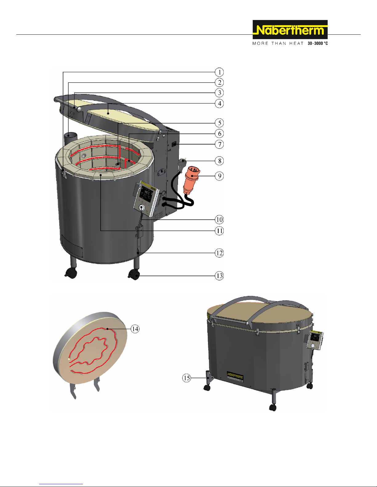
Example: Top loader model Top 60
Example: Lid from the fusing top loader Model F 30
Example: Fusing top loader Model F 220
Fig. 1: Example: Top loader model Top … and Fusing top loader Model F … (similar to picture)
Page 8
8
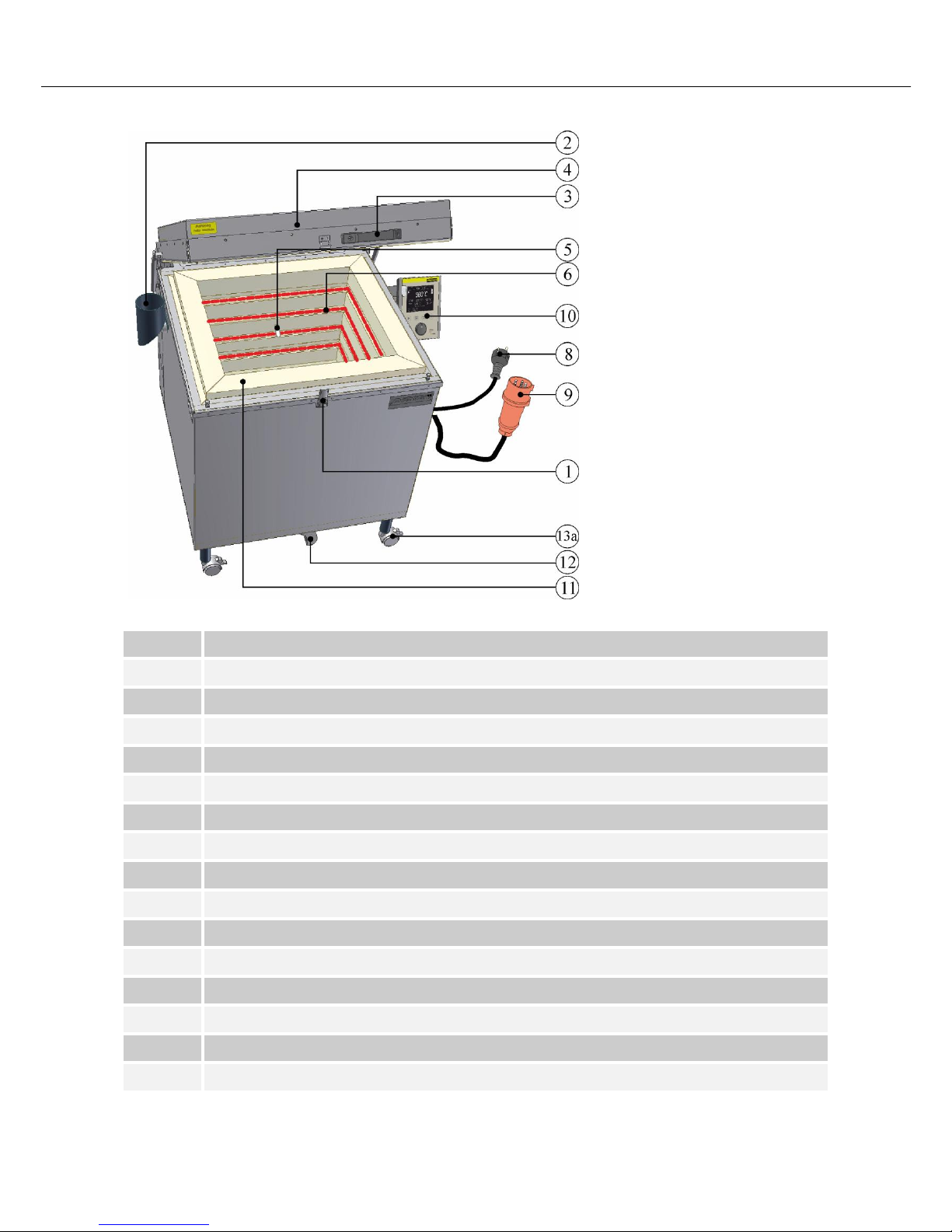
Pos: 13 /TD/Einleitung/Lieferumfang/Öfen/G esamtübersicht Toplader HO (Modell 2015) @ 155\mod_1494222849223_51.d ocx @ 640342 @ @ 1
Fig. 2: Example: Top loader Model HO 100 (similar to picture)
Pos: 14 /TD/Einleitung/Lieferumfang/Öfen/G esamtübersicht_M01.0062_Tabelle Nr. und Benennung der verbauten Teile - T op, F und HO @ 155\mod_1494223066 523_51.docx @ 640368 @ @ 1
No.
Designation
1
Adjustable lid closure
2
Bypass connection (Top + HO model only)
3
Handle
4
Lid 5 Thermocouple
6
Heating element
7
Power switch (to switch the furnace on and off)
8
Power plug (up to 3600 watts)
9
Power plug (from 5500 watts)
10
Controller
11
Insulation
12
Supply air valve
13
Castor with locking brake
13a
Castor (with locking brake from Model HO 70 + HO 100)
14
Lid heating (Fusing top loader F …)
Page 9
9
No.
Designation
15
Base frame (Model Top 220/Fusing top loader from Model F 75)
Pos: 15 /TD/Einleitung/Produktbeschreibung/ Öfen/Überschrift - Entschlüsselung d er Modellbezeichnung @ 2\mod_1184 245078907_51.docx @ 19775 @ 3 @ 1
1.2.1 Key to the Model Names
Pos: 16 /TD/Einleitung/Produktbeschreibung/ Öfen/Entschlüssellung der Modellbez eichnung Top, HO und F @ 13\mod_12 89220515672_51.docx @ 107253 @ @ 1
Example
Explanation
Top 60/Leco
Top = Top loader, round/oval
HO = Top loader, rectangular
F = Fusing top loader
Top 60/Leco
X = Liters furnace chamber (volume in liters)
Top 60/Leco
L = low
LE = low energy
R = rapid
Top 60/Leco
eco = economy
Pos: 17 /TD/Einleitung/Produktbeschreibung/ Öfen/Entschlüssellung der Modellbez eichnung Top, HO und F - Grafik (Mod ell 2015) @ 104\mod_1444119915280_51.d ocx @ 412700 @ @ 1
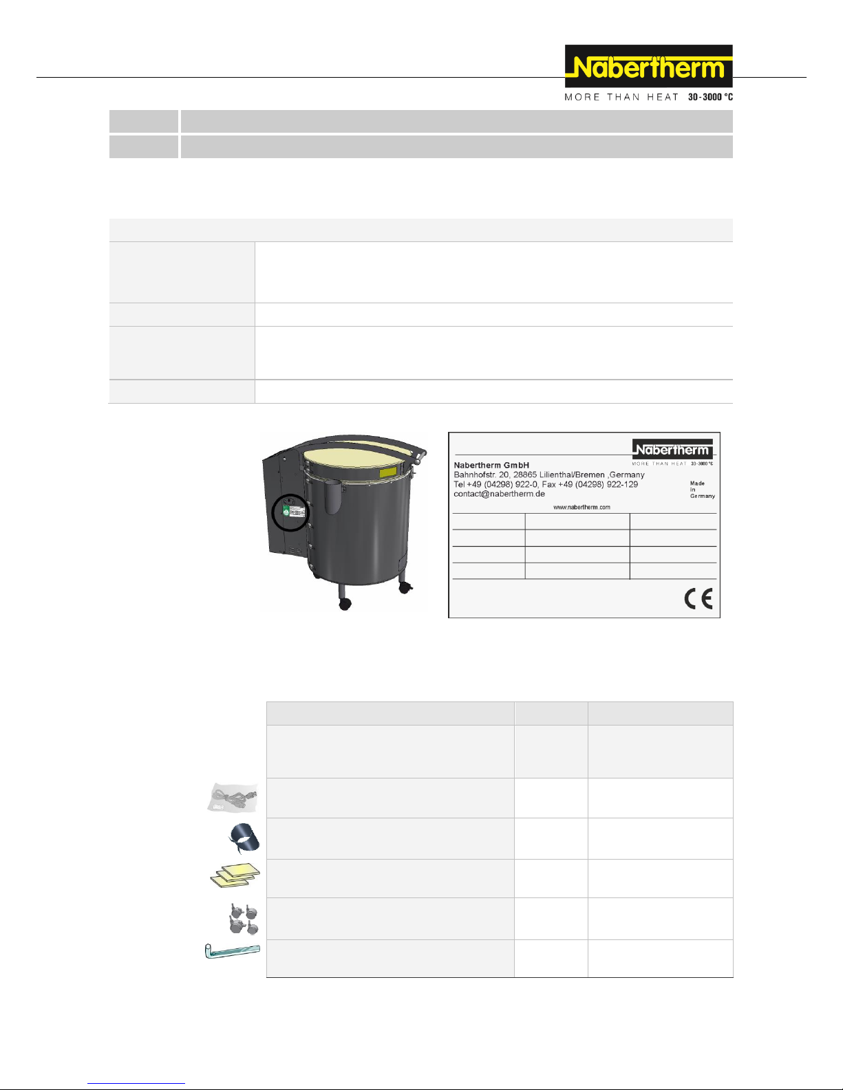
Fig. 3: Example: Model name (type plate)
Pos: 18 /TD/Einleitung/Lieferumfang/Öfen/Üb erschrift - Lieferumfang @ 0\mod_11 67822508130_51.docx @ 5112 @ 2 @ 1
1.3 Scope of Delivery
Pos: 19 /TD/Einleitung/Lieferumfang/Öf en/Lieferumfang - Top-HO-F @ 156\mod_1 494507874135_51.docx @ 643000 @ @ 1
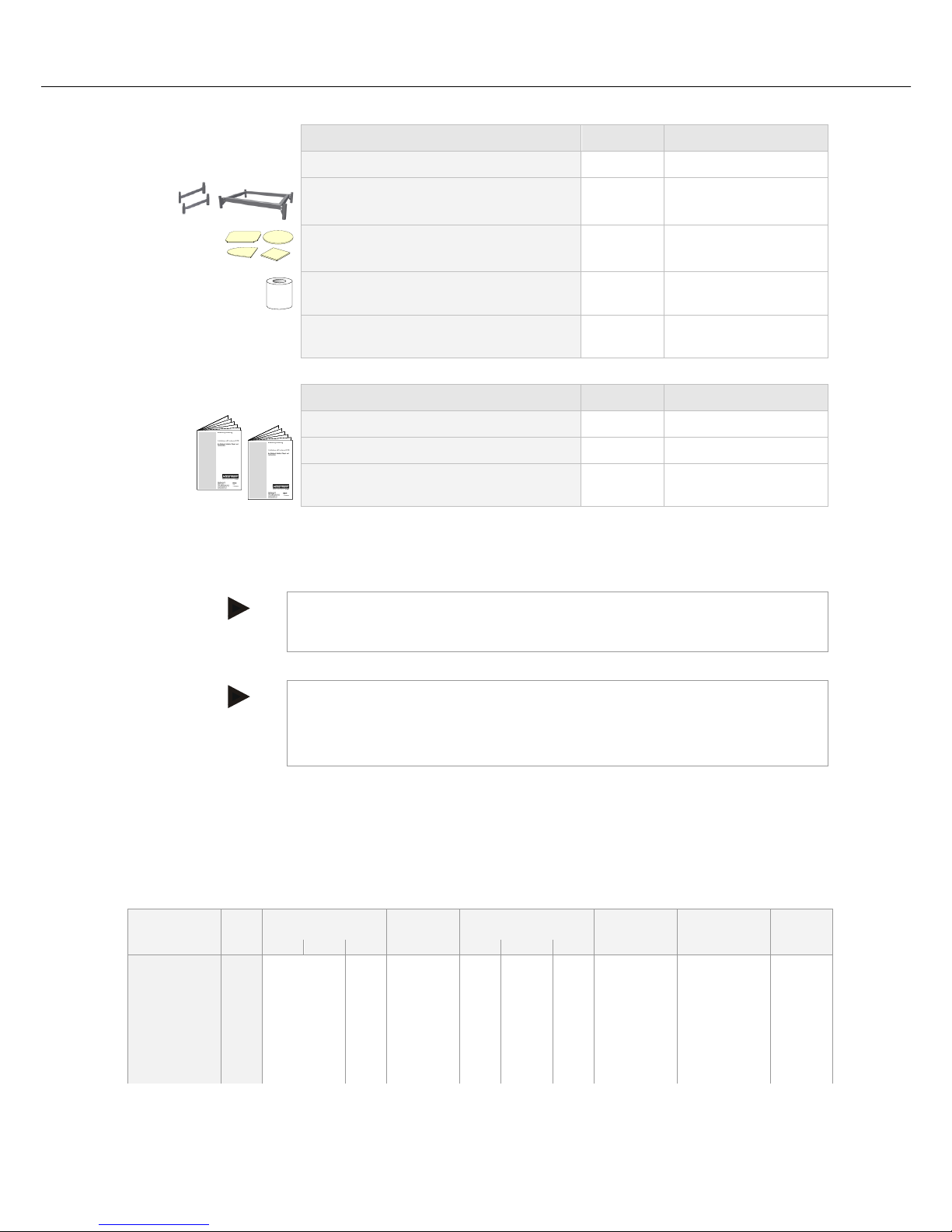
The scope of delivery includes:
Furnace components
Quantity
Comment
-Furnace model Top …,
-Furnace model HO … or
-Furnace model F …
1 x
Nabertherm GmbH
Power cable1)
1 x
Nabertherm GmbH
Bypass connection1)
(for furnace models Top and HO)
1 x
Nabertherm GmbH
Ceramic shelves
(691600956 – 80x80x10 mm)
3 x
Nabertherm GmbH
Castors
4 to 6x3)
Nabertherm GmbH
Hex key1)
(for furnace models Top and F)
1 x
Nabertherm GmbH
Top 160 SN 123456 2017
TOP1603BN1 1320 °C
-
-
400 V 3/N/PE~
-
50/60 Hz
13,0/13,0/13,0 A
9,0 kW
Page 10
10
Furnace components
Quantity
Comment
Accessories:
Adjustable base1) (for furnace models
Top 45/60 or F 75/F 110)
1 x
Nabertherm GmbH
Shelve/s2) for furnace models Top, HO and F
4)
Nabertherm GmbH
Props
2)
4)
Nabertherm GmbH
Other components, variable depending on
the particular furnace
- - -
See the shipping
documents
Document type
Quantity
Comment
Furnace operating manual
1 x
Nabertherm GmbH
Controller operating manual
1 x
Nabertherm GmbH
Other documents, variable depending on the
particular furnace
- - -
1) in delivery scope depending on the design/furnace model
2) in delivery scope as required, see shipping documents
3) quantity depends on furnace model
4) quantity as required, see shipping documents
Note
Store all documents carefully. All the functions of this furnace were tested during
manufacturing and prior to shipping.
Pos: 20 /TD/Betrieb_Bedienung/Die mitgelief erten Unterlagen beinhalten nicht zwangsl äufig elektrische Schaltpläne bzw. Pneu ma ... @ 47\mod_1380028074616_ 51.docx @ 247668 @ @ 1
Note
The documents included do not always contain the electrical schematics and pneumatic
diagrams.
If you need the respective diagrams, they can be ordered from Nabertherm Service.
Pos: 21 /TD/Einleitung/Technische Daten/Ö fen/Überschrift - Technische Daten - mit Hinweis @ 0\mod_1167822840737_51. docx @ 5121 @ 1 @ 1
2 Specifications
Electrical specifications are on the type plate located on the side of the furnace.
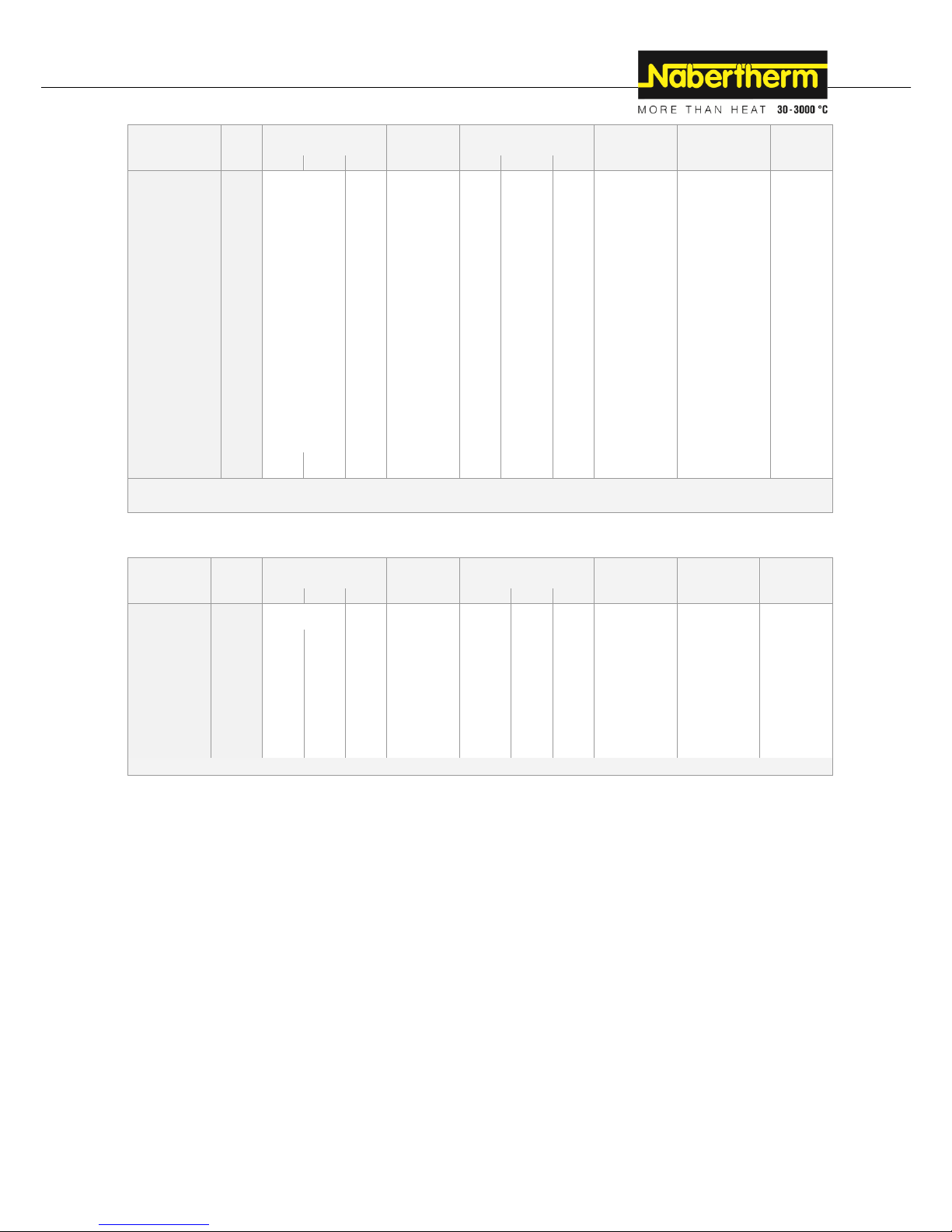
Pos: 22 /TD/Einleitung/Technische Daten/Ö fen/Modell-Tabelle für Top-Öfen - 1 (M odell 2015) 1200 °C und 1320°C @ 15 5\mod_1493981954113_51.docx @ 64028 6 @ @ 1
Furnace model Top
Model
Tmax
Inner dimensions in
mm
Volume
Outer dimensions in
mm
Connected
load
Electrical
connection
Weight
°C w d h in l W D H kW
in kg
Top 16/R
1320
Ø 290
230
16
440
650
530
2.6
1-phase
32
Top 45eco
1320
Ø 410
340
45
580
880
760
2.9
1-phase
62
Top 45
1320
Ø 410
340
45
580
880
760
3.6
1-phase
62
Top 45/R
1320
Ø 410
340
45
580
880
760
5.5
3-phase1
62
Top 60
1200
Ø 410
460
60
580
870
870
3.6
1-phase
72
Page 11
11
Model
Tmax
Inner dimensions in
mm
Volume
Outer dimensions in
mm
Connected
load
Electrical
connection
Weight
°C w d h in l W D H kW
in kg
Top 60Leco
1200
Ø 410
460
60
580
870
870
2.9
1-phase
72
Top 60eco
1320
Ø 410
460
60
580
870
870
3.6
1-phase
72
Top 60/R
1320
Ø 410
460
60
580
870
870
5.5
3-phase1
72
Top 80
1320
Ø 480
460
80
660
950
890
5.5
3-phase1
100
Top 100 LE
1320
Ø 480
570
100
660
970
1000
6.0
1-phase2
102
Top 100
1320
Ø 480
570
100
660
970
1000
7.0
3-phase
102
Top 130
1320
Ø 590
460
130
770
1090
920
9.0
3-phase
110
Top 140 LE
1320
Ø 550
570
140
730
1040
1020
6.0
1-phase2
124
Top 140
1320
Ø 550
570
140
730
1040
1020
9.0
3-phase
124
Top 160
1320
Ø 590
570
160
770
1090
1030
9.0
3-phase
130
Top 190
1320
Ø 590
690
190
770
1090
1150
11.0
3-phase
146
Top 220
1320
930
590
460
220
1100
1030
930
15.0
3-phase
150
1
Heating only between two phases
2
Fusing of 32 A if connected to 230 V
Pos: 23 /TD/Einleitung/Technische Daten/Ö fen/Modell-Tabelle für F-Öfen - 1 @ 13 \mod_1289317404179_51.docx @ 1074 19 @ @ 1
Furnace model F
Model
Tmax
Inner dimensions in
mm
Floor
space
Outer dimensions in
mm
Connected
load
Electrical
connection
Weight
°C w d h in m2
W D H
kW
in kg
F 30
950
Ø 410
230
0.13
650
800
500
2.0
1-phase
50
F 75 L
950
750
520
230
0.33
950
880
680
3.6
1-phase
80
F 75
950
750
520
230
0.33
950
880
680
5.5
3-phase
80
F 110 LE
950
930
590
230
0.47
1120
950
680
6.0
1-phase1
95
F 110
950
930
590
230
0.47
1120
950
680
7.5
3-phase
95
F 220
950
930
590
460
0.47
1120
950
910
15.0
3-phase
115
1
Fusing of 32 A if connected to 230 V
Page 12
12
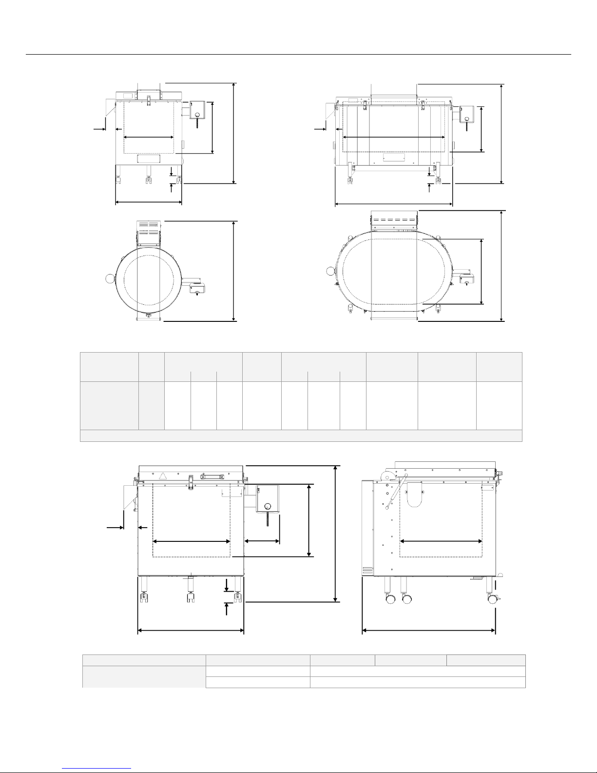
Pos: 24 /TD/Einleitung/Technische Daten/Ö fen/Modell-Tabelle für Top und F-Öfen - Z eichnung (Modell 2015) @ 104\mod_1444133795 726_51.docx @ 412726 @ @ 1
Fig. 4: Top 16 – 190 / F 30 Top 220 / F 75 – F 22
Pos: 25 /TD/Einleitung/Technische Daten/Ö fen/Modell-Tabelle für HO-Öfen - 1 @ 13\mod_1289317 483630_51.docx @ 107442 @ @ 1
Furnace model HO
Model
Tmax
Inner dimensions in
mm
Volume
Outer dimensions in
mm
Connected
load
Electrical
connection
Weight
°C w d h in l W D H kW
in kg
HO 70/L
1200
440
380
420
70
640
770
780
3.6
1-phase
120
HO 70/R
1300
440
380
420
70
640
770
780
5.5
3-phase1
120
HO 100
1300
480
430
490
100
680
820
850
5.5
3-phase1
160
1
Heating only between two phases
Pos: 26 /TD/Einleitung/Technische Daten/Ö fen/Modell-Tabelle für HO-Öfen - Zeich nung (Modell 2015) @ 104\mod_144413 4039128_51.docx @ 412752 @ @ 1
Fig. 5: Dimensions of model HO
Pos: 27 /TD/Einleitung/Technische Daten/Ö fen/Tabelle für alle Top-HO und F-Öf en - 1 @ 13\mod_1289381485867_51.d ocx @ 107493 @ @ 1
Electrical connection
Voltage (V)
1-phase:
3-phase:
Special voltage:
Furnace model
See type plate on furnace
Frequency:
50 or 60 Hz
W
D
H w h d W D Ø h H
90
90
65
65
W
D
H w h
d
65
90
200
Page 13

13
Thermal protection class
Furnaces:
according to DIN EN 60519-2
without safety controller: Class 0
(in case of fault, no protection for furnace or charge)
with safety controller: Class 2
(in case of fault, furnace and charge protected)
Protection rating
Furnaces:
1
Protection type
IP20
Ambient conditions for
electrical equipment
Temperature:
Humidity:
+5 °C to +40 °C
max. 80 % non condensing
Weights
Furnace with accessories
Varies (see shipping documents)
Pos: 28 /TD/Einleitung/Technische Daten/Ö fen/Tabelle Dauerschalldruckpegel < 80 d B(A) - 2 @ 1\mod_1170750985488_5 1.docx @ 8913 @ @ 1
Emissions
Continuous sound pressure level:
< 80 dB(A)
Pos: 29 /TD/Einleitung/Gewährleistung_Haft ung/Überschrift - Gewährleistung und H aftung 1.1 @ 0\mod_1167822979492_ 51.docx @ 5130 @ 2 @ 1
2.1 Warranty and Liability
Pos: 30 /TD/Einleitung/Gewährleistung_Haft ung/Öfen und Schaltanlagen - Gewä hrleistung und Haftung @ 0\mod_1157536 440972_51.docx @ 1569 @ @ 1
§
As regards warranty and liability, the normal Nabertherm warranty terms apply,
unless individual terms and conditions have been agreed. However, the following
conditions also apply:
Warranty and liability claims for personal injury or damage to property shall be excluded if
they are attributable to one or more of the following causes:
All persons involved in operation, installation, maintenance, or repair of the furnace
must have read and understood the operating instructions. No liability will be accepted
for damage or disruption to operation resulting from non-compliance with the
operating instructions.
Not using the furnace as intended
Improper installation, start-up, operation, or maintenance of the furnace,
Operation of the furnace with defective safety equipment or improperly installed or
non-functioning safety and protective equipment
Not observing the information in the operating instructions with respect to
transportation, storage, installation, start-up, operation, maintenance, or equipping the
furnace
Making unauthorized changes to the furnace
Making unauthorized changes to the operating parameters
Making unauthorized changes to the parameterization, the settings, or the program
Nabertherm accepts absolutely no liability for damage caused by using parts that are
not original Nabertherm parts. Original parts and accessories are designed especially
for Nabertherm furnaces. Replace parts only with original Nabertherm parts.
Otherwise the warranty will be void.
Catastrophes due to third-party causes and force majeure
Page 14
14
Pos: 31 /TD/Sicherheit/Überschrift - Sic herheit @ 0\mod_1158843961540_51.doc x @ 3103 @ 1 @ 1
3 Safety
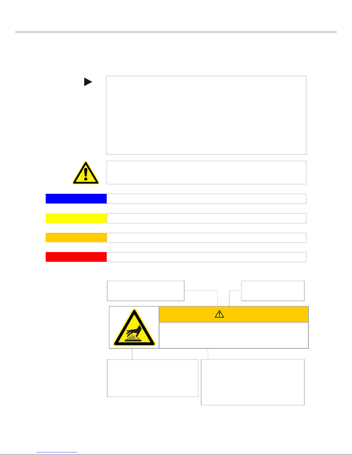
Pos: 32 /TD/Sicherheit/Sicherheitssymbole/ Warnhinweise-ISO-ANSI/Erläuterung AN SI Z535.6 @ 8\mod_124332355888 1_51.docx @ 57444 @ 2 @ 1
3.1 Explanation of the Symbols and Warnings
Note
In the following operating instructions, specific warnings are given to draw attention to
residual risks that cannot be avoided when the furnace is operating. These residual risks
include dangers for humans/products/ the furnace, and the environment.
The symbols used in the operating instructions are especially intended to draw attention to
safety information.
The symbols used cannot replace the text of the safety information. Therefore, always
read the entire text.
Graphic symbols correspond to ISO 3864. In accordance with the American National
Standard Institute (ANSI) Z535.6 the following warning information and words are used
in this document:
The general hazard symbol, in combination with the words CAUTION, WARNING and
DANGER warns about the risk of serious injury. Observe the following information to
prevent injury or death.
NOTE
Refers to a hazard that could damage or destroy the equipment.
CAUTION
Refers to a hazard with a minor or medium risk of injury.
WARNING
Refers to a hazard that could cause death, serious or irreversible injury.
DANGER
Refers to a hazard that could directly cause death, serious or irreversible injury.
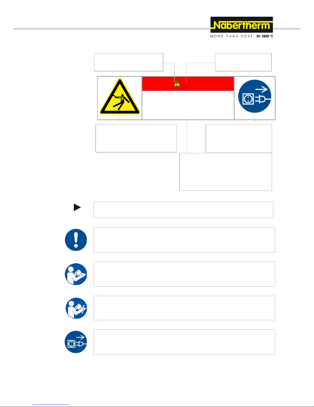
Structure of the Warning: All Warnings are Structured as Follows
WARNING
• Type and source of the danger
• Consequences of non-compliance
• Action to prevent danger
Hazard Symbol
Indicates the risk of injury
Signal Word
Classifies the danger
Graphical Symbols (optional)
According to ISO 3864:
Consequences, measures, and
prohibitions
Reference Texts:
• Type and source of the danger
• Possible consequences of non-
compliance
• Measures/Prohibitions
Page 15
15
or
DANGER
• Type and source of the danger
• Consequences of non-compliance
• Action to prevent danger
Pos: 33 /TD/Sicherheit/Sicherheitssymbole/ Warnhinweise-ISO-ANSI/Überschrift - Hin weissymbole in der Anleitung (Einzug Mit te) @ 9\mod_1247053429626_51.d ocx @ 62751 @ @ 1
Information Symbols in the Instructions:
Pos: 34 /TD/Sicherheit/Sicherheitssymbole/ Warnhinweise-ISO-ANSI/Hinweis - U nter diesem Symbol erhalten Sie Anweisu ngshinweise und ... @ 9\mod_124705393 2311_51.docx @ 62785 @ @ 1
Note
Below this symbol you will find instructions and particularly useful information.
Pos: 35 /TD/Sicherheit/Sicherheitssymbole/ Warnhinweise-ISO-ANSI/Piktogram m in der Anleitung - Gebot - Gebotszeichen - Wichtige Gebote sind zu befolgen @ 9\ mod_1247056175982_51.docx @ 62853 @ @ 1
Rule - Rule Sign
This symbol draws attention to important rules that must be observed. Rule signs protect
people against injury and show what is to be done in certain situations.
Pos: 36 /TD/Sicherheit/Sicherheitssymbole/ Warnhinweise-ISO-ANSI/Piktogram m in der Anleitung - Gebot - Wichtige Inform ation für den Bediener @ 9\mod_124705 3200729_51.docx @ 62717 @ @ 1
Rule – Important Information for Operators
This symbol draws the operator's attention to important information and operating
instructions that must be observed.
Pos: 37 /TD/Sicherheit/Sicherheitssymbole/ Warnhinweise-ISO-ANSI/Piktogram m in der Anleitung - Gebot - Wichtige Inform ation für das Wartungspersonal @ 9\m od_1247053206042_51.docx @ 62734 @ @ 1
Rule – Important Information for Maintenance Personnel
This symbol draws the maintenance personnel's attention to important operating and
maintenance instructions (service) that must be observed.
Pos: 38 /TD/Sicherheit/Sicherheitssymbole/ Warnhinweise-ISO-ANSI/Piktogram m in der Anleitung - Gebot - Netzstecker zieh en @ 9\mod_1247055471526_51.docx @ 62836 @ @ 1
Rule – Pull Out the Power Plug
This symbol tells the operator to pull out the power plug.
Graphical Symbols (optional)
According to ISO 3864:
Consequences, measures, and
prohibitions
Reference Texts:
• Type and source of the danger
• Possible consequences of non-compliance
• Measures/prohibitions
Graphical Symbols
(optional) According to ISO
3864:
Instructions or prohibitions
Hazard Symbol
Indicates the risk of injury
Signal Word
Classifies the danger
Page 16
16
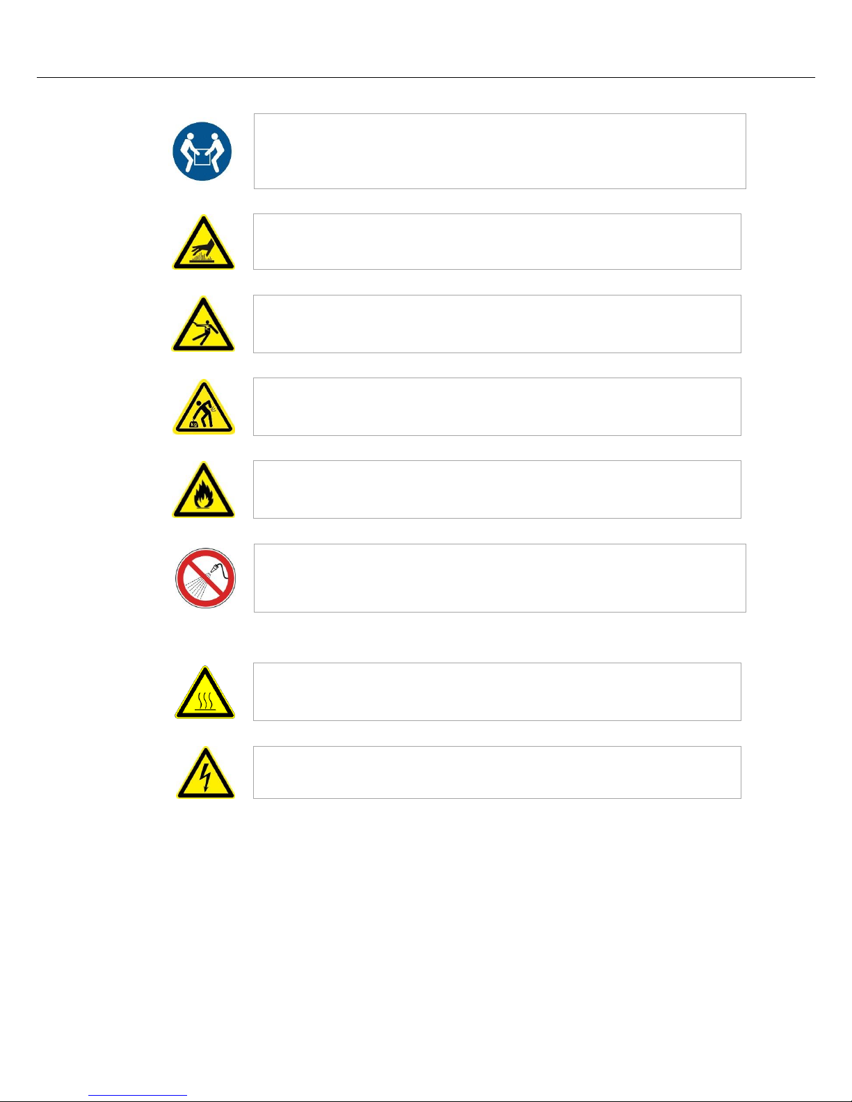
Pos: 39 /TD/Sicherheit/Sicherheitssymbole/ Warnhinweise-ISO-ANSI/Piktogram m in der Anleitung - Gebot - Anheben mit mehreren Personen @ 9\mod_1247063058 002_51.docx @ 62938 @ @ 1
Rule – Lift only with Several People
This symbol draws the personnel's attention to the fact that this device may only be lifted
and moved to its final destination by several people.
Pos: 40 /TD/Sicherheit/Sicherheitssymbole/ Warnhinweise-ISO-ANSI/Piktogram m in der Anleitung - Warnung - Heiße Oberflä che - Oberfläche nicht berühren @ 9\ mod_1247054774780_51.docx @ 62802 @ @ 1
Warning – Hot Surface, Do Not Touch
This symbol warns the operator that the surface is hot and should not be touched.
Pos: 41 /TD/Sicherheit/Sicherheitssymbole/ Warnhinweise-ISO-ANSI/Piktogram m in der Anleitung - Warnung - elektrischer Schlag - zur Vermeidung Anweisung folg en @ 9\mod_1247055093892_51.docx @ 62819 @ @ 1
Warning – Danger of Electric Shock
This symbol warns the operator that there is a risk of an electric shock if the following
warnings are not heeded.
Pos: 42 /TD/Sicherheit/Sicherheitssymbole/ Warnhinweise-ISO-ANSI/Piktogram m in der Anleitung - Warnung - Heben schwer er Lasten @ 9\mod_1247059891358_5 1.docx @ 62887 @ @ 1
Warning – Danger if Heavy Loads are Lifted
This symbol warns the operator of the potential dangers of lifting heavy loads. Ignoring
this can lead to injury.
Pos: 43 /TD/Sicherheit/Sicherheitssymbole/ Warnhinweise-ISO-ANSI/Piktogram m in der Anleitung - Warnung - Brandgefa hr @ 9\mod_1251445272822_51.docx @ 6 5437 @ @ 1
Warning – Fire Danger
This symbol warns operators of the danger of fire if the following information is not
followed.
Pos: 44 /TD/Sicherheit/Sicherheitssymbole/ Warnhinweise-ISO-ANSI/Piktogram m in der Anleitung - Gefahr - nicht mit Wasser überschütten @ 9\mod_124782641 0886_51.docx @ 63819 @ @ 1
Prohibited – Important Information for Operators
This symbol warns the operator that water or cleaning products must NOT be poured over
the objects. A high-pressure cleaning device must also not be used.
Pos: 45 /TD/Sicherheit/Sicherheitssymbole/ Warnhinweise-ISO-ANSI/Überschrift - Warnhinweissymbole an der Anlage @ 9\mod_1247053700273_51.docx @ 627 68 @ @ 1
Warning Signs on the Furnace:
Pos: 46 /TD/Sicherheit/Sicherheitssymbole/ Warnhinweise-ISO-ANSI/Piktogram m an der Anlage - Warnung - Gefahr vor h eißer Oberfläche und Verbrennung @ 9\ mod_1247052957145_51.docx @ 62700 @ @ 1
Warning – Hot Surface, Danger of Burning – Do Not Touch
You may not always realize that surfaces, such as furnace components, furnace walls,
doors and materials, and even liquids are hot. Do not touch the surface.
Pos: 47 /TD/Sicherheit/Sicherheitssymbole/ Warnhinweise-ISO-ANSI/Piktogram m an der Anlage - Warnung - Gefahren durch elektrischen Strom @ 9\mod_12470 52639824_51.docx @ 62683 @ @ 1
Warning – Danger of Electric Shock!
Warning, dangerous electric voltage
Page 17
17
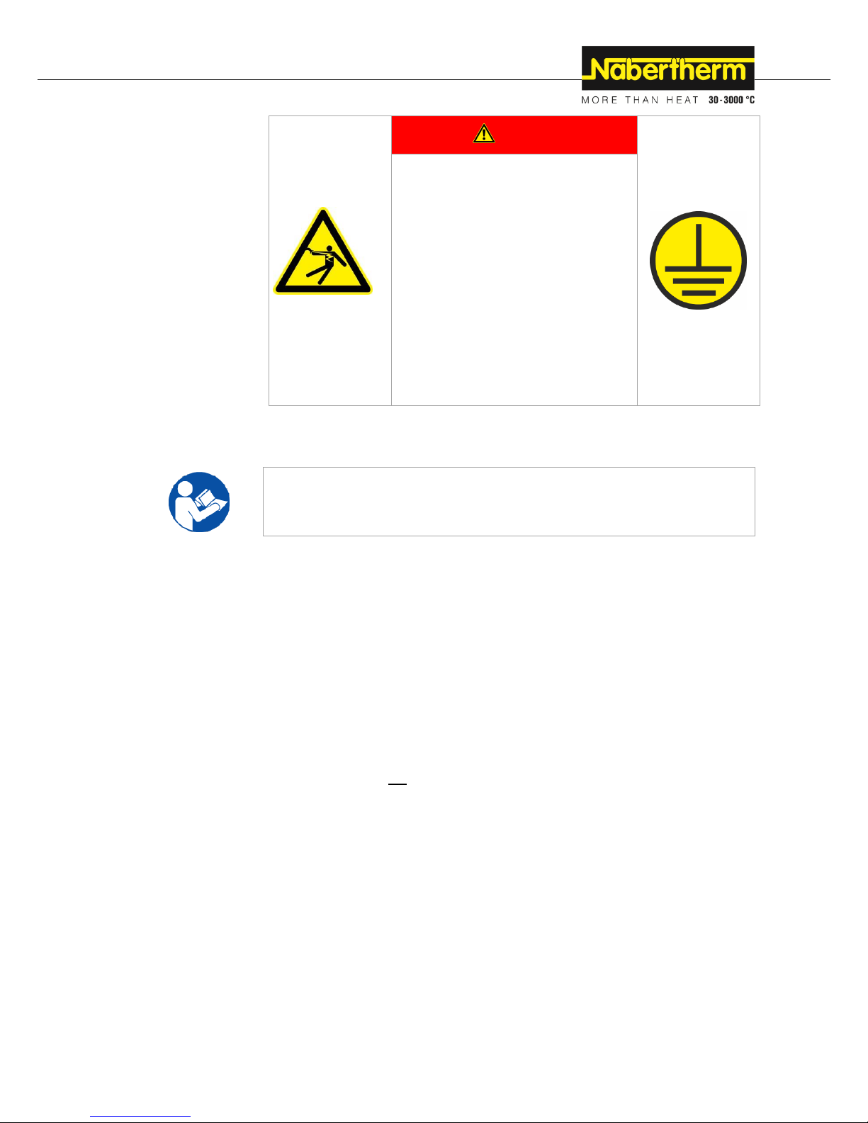
Pos: 48 /TD/Sicherheit/Sicherheitssymbole/ Warnhinweise-ISO-ANSI/Warnsymbol_ Gefahr - Gefahr durch fehlende oder nic ht korrekt angeschlossene Erdung an ... @ 85\mod_1423745935634_51.docx @ 359461 @ @ 1
DANGER
• Danger from electrocution
• If there is no earth connection, or the
earth connection is poorly connected,
the result may be a deadly electrical
shock.
• Do not insert any metallic objects such as
thermocouples, sensors or tools into the
furnace chamber without having
previously ensured that the plant has been
correctly earthed. Entrust the job of
making a earth connection between the
object and the furnace housing to a
qualified electrical technician. Any
objects inserted into the furnace must be
inserted only through those openings
intended for this purpose.
Pos: 49 /TD/Sicherheit/Überschrift - Besti mmungsgemäße Verwendung @ 0\ mod_1167823503921_51.docx @ 5148 @ 2 @ 1
3.2 Defined Application
Pos: 50 /TD/Sicherheit/Bestimmungsgemäß e Verwendung allgemeiner Ofen-Anlage n - Teil 1 @ 45\mod_137723815939 1_51.docx @ 241740 @ @ 1
Safety
The Nabertherm furnace was designed and built in conformance with a careful selection
of the applicable harmonized standards and other technical specifications. Hence, it
corresponds to the state of the art and assures the greatest degree of safety.
Pos: 51 /TD/Sicherheit/Bestimmungsgemäß e Verwendung Top-HO und F-Öfen @ 13\mod_1289384913818_51.docx @ 107516 @ @ 1
Furnaces in the Top and HO series are electrically heated furnaces for firing ceramics,
glass fusing, glass and porcelain painting. Furnaces in the F series are for glass fusing, glass
and porcelain painting.
Pos: 52 /TD/Sicherheit/Überschrift - Nicht b estimmungsgemäß ist: (Einzug Mitte) @ 80\mod_1418806747958_51.docx @ 3 47220 @ @ 1
Improper furnace operation:
Pos: 53 /TD/Sicherheit/Eine andere oder darüber hinausgehende Benutzung, wie z. B. die Verarbeitung ... @ 45\mod_137 7242071687_51.docx @ 242040 @ @ 1
Safety
Any other use, such as processing of products other than those for which the furnace
was intended as well as handling hazardous materials or materials dangerous to health
is deemed IMPROPER and such uses must be approved in writing by Nabertherm.
Pos: 54 /TD/Sicherheit/dieser Ofen ist NICHT dafür bestimmt durch Personen (einschließlic h Kinder) mit eingeschränkten ... @ 45\mod_1377501786408_51.docx @ 24249 0 @ @ 1
This furnace is NOT used by certain persons (including children) with restricted
physical, sensorial or mental capabilities or who have insufficient experience
and/or insufficient knowledge, unless they are supervised by a person who is
responsible for their safety or are instructed in how to use the furnace. Children
should be supervised to make sure that they do not play with the furnace.
Pos: 55 /TD/Sicherheit/Der Ofen ist nicht für die Erwärmung von Nahrungsmitteln zum Verzehr zu verwenden. @ 53\mod_1 389787274556_51.docx @ 262780 @ @ 1
The furnace must not not be used for heating food.
Pos: 56 /TD/Sicherheit/Veränderungen am Of en, müssen mit Nabertherm schriftlich a bgestimmt werden ... @ 45\mod_13 77243398694_51.docx @ 242240 @ @ 1
The set-up instructions and safety regulations must be followed, otherwise the furnace
will be considered improperly used, effectively cancelling any claims against
Nabertherm GmbH. The EC Declaration of Conformity will cease to be valid if any
modifications are made to the machine without our approval.
Pos: 57 /TD/Sicherheit/Die Aufstellhinweise und Sicherheitsbestimmungen sind einz uhalten, andernfalls gilt der Ofen als ... @ 45\mod_1377243410507_51.docx @ 242265 @ @ 1
The set-up instructions and safety regulations must be followed, otherwise the furnace
will be considered improperly used, effectively cancelling any claims against
Nabertherm GmbH.
Pos: 58 /TD/Sicherheit/Der Betrieb mit Kr aftquellen, Produkten, Betriebsmitteln, Hilfssto ffen, Lösungsmitteln ... - 2 @ 53\ mod_1389787294041_51.docx @ 262830 @ @ 1
Operation with power sources, products, operating equipment, auxiliary materials,
solvents, etc., which are listed as hazardous or which may in any way harm the health
of the personnel operating the furnace is prohibited.
Page 18
18
Pos: 59 /TD/Sicherheit/Überschrift - Für hieraus resultierende Schäden haftet der Betreiber (Einzug Mitte) @ 10\mod_125 6731411117_51.docx @ 68223 @ @ 1
The operator is liable for any resulting damages.
Pos: 60 /TD/Sicherheit/Das Betreiben des Ofens ist nur nach der in dieser Betriebs anleitung beschriebenen Vorgehensweise .. @ 53\mod_1389787305804_51.docx @ 262855 @ @ 1
The furnace may only be operated in the manner described in these operating
instructions, i.e., the operating instructions must be completely read and understood.
Pos: 61 /TD/Sicherheit/Von den im Ofen ei ngesetzten Materialien bzw. Ausgasunge n können sich unter Umständen Schadstoff e .. @ 45\mod_137724339221 7_51.docx @ 242065 @ @ 1
Under certain circumstances gases or materials may be released from the materials in
the furnaces that settle on the insulation or the heating elements and destroy them. If
applicable, read the labels and instructions on the packaging of materials that
you use.
Pos: 62 /TD/Sicherheit/Die Aufstellhinweise und Sicherheitsbestimmungen sind einz uhalten, andernfalls gilt der Ofen als ... @ 45\mod_1377243410507_51.docx @ 242265 @ @ 1
The set-up instructions and safety regulations must be followed, otherwise the furnace
will be considered improperly used, effectively cancelling any claims against
Nabertherm GmbH.
Pos: 63 /TD/Sicherheit/Das Öffnen des Ofens i m heißen Zustand über 200 °C (392 °F) kann zu einem erhöhtem Verschleiß ... @ 39\mod_1364289911635_51.docx @ 219945 @ @ 1
Opening the furnace while it is still hot, over 200 °C (392 °F), can lead to increased
wear of the following components: insulation, door seal, heating elements and furnace
housing. No liability shall be accepted for any damage to the goods or the furnace
resulting from non-compliance with this warning.
Pos: 64 /TD/Allgemeine Hinweise (für alle Anleitungen)/Hinweis - Dieser Ofen ist für die private und gewerbliche Anwendung ... Der Ofen ist nicht für ... @ 45\mod_1 377239313841_51.docx @ 241765 @ @ 1
Safety
This furnace was designed for private and commercial use. The furnace is NOT to be
used for heating food, animals, wood, grains, etc.
The furnace must NOT be used to heat the workplace.
Do NOT use the furnace to melt ice or for similar purposes.
Do NOT use the furnace as a clothes dryer.
Pos: 65 /TD/Allgemeine Hinweise (für alle Anleitungen)/Hinweis - Es gelten die Sic herheitshinweise der einzelnen Kapitel. @ 34\mod_1357906319399_51.docx @ 203020 @ @ 1
Note
See safety instructions in the individual sections.
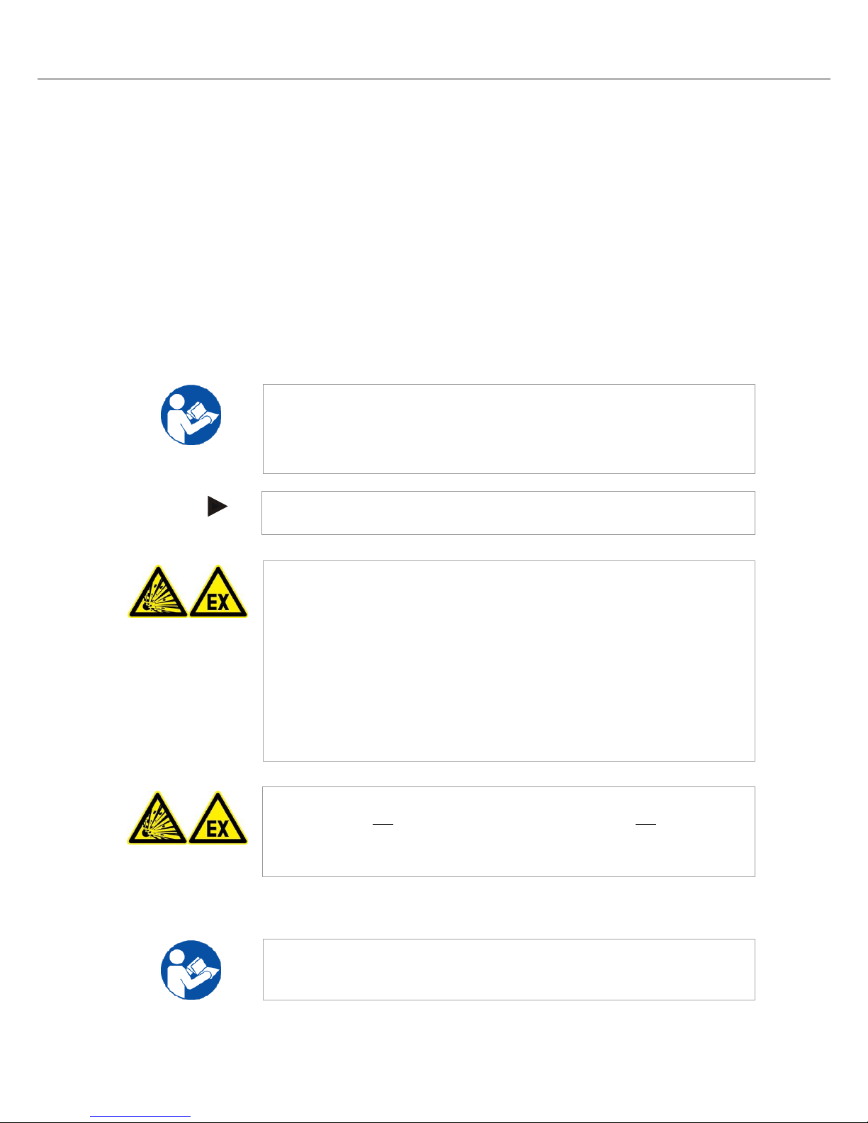
Pos: 66 /TD/Allgemeine Hinweise (für alle Anleitungen)/Hinweis - Dieser Ofen verfügt über keine Sicherheitstechnik für Pr ozesse, ..-nicht brennbare Gase @ 8\mo d_1235038699771_51.docx @ 51483 @ @ 1
Note
The furnace must not be operated with explosive gases or mixtures or with
explosive gases or mixtures that form during the process.
This furnace has no safety technology for processes in which combustible mixtures
can form, such as debinding.
If the furnace is to be used for such processes, the concentration of organic gases must
never exceed 3 % of the lower explosive limit (LEL) in the furnace. This requirement
not only applies to normal operation, but also especially to exceptions, such as process
malfunctions (e.g. due to the breakdown of a unit, etc.). Ensure adequate extraction
and ventilation of the furnace.
Nabertherm offers a wide range of furnaces that were especially developed for processes
with flammable gases.
Pos: 67 /TD/Allgemeine Hinweise (für alle Anleitungen)/Hinweis - Dieses Produ kt entspricht nicht der ATEX-Richtlinie und darf nicht ..-nicht brennbare Gase @ 2\m od_1184228756893_51.docx @ 19686 @ @ 1
Note
This product does not comply with the ATEX Directive and may not be used in
ignitable atmospheres. The system must not be operated with explosive gases or
mixtures and it must be ensured that explosive gases or mixtures do not form during
the process.
Pos: 68 /TD/Sicherheit/Überschrift - Anf orderungen an den Betreiber der Anlage @ 0\mod_1167823775531_51.docx @ 515 7 @ 2 @ 1
3.3 Requirements for the Furnace Operator
Pos: 69 /TD/Sicherheit/Anforderungen an de n Betreiber der Anlage - Die Aufstell hinweise und Sicherheits ... (Ofen) @ 45\ mod_1377241972892_51.docx @ 242015 @ @ 1
The set-up instructions and safety regulations must be followed, otherwise the furnace
will be deemed to have been used improperly, effectively cancelling any claims against
Nabertherm GmbH.
Page 19
19
This level of safety can be achieved only if all the necessary measures have been taken. It
depends on the furnace operator's diligence in planning these measures and controlling how
they are carried out.
Pos: 70 /TD/Sicherheit/Überschrift - Der Betreiber muss sicherstellen, dass @ 45\ mod_1377501770051_51.docx @ 24246 5 @ @ 1
The operator must ensure that
Pos: 71 /TD/Sicherheit/dieser Ofen ist NICHT dafür bestimmt durch Personen (einschließlic h Kinder) mit eingeschränkten ... @ 45\mod_1377501786408_51.docx @ 24249 0 @ @ 1
This furnace is NOT used by certain persons (including children) with restricted
physical, sensorial or mental capabilities or who have insufficient experience
and/or insufficient knowledge, unless they are supervised by a person who is
responsible for their safety or are instructed in how to use the furnace. Children
should be supervised to make sure that they do not play with the furnace.
Pos: 72 /TD/Sicherheit/beim Brennen von K eramik, des Tones bzw. der Glasur können ... @ 45\mod_1377501792291_51.d ocx @ 242515 @ @ 1
When ceramics, clay, or glaze are fired, they can emit gases and vapors that are
harmful to your health. It is therefore necessary to make sure that the "exhaust gases"
emitted from the exhaust air opening are directed outdoors in a suitable manner
(ventilate the working area). If adequate ventilation cannot be ensured at the working
area, the "exhaust gases" must be removed via a pipe (see "venting exhaust fumes").
Pos: 73 /TD/Sicherheit/von den Materialien, die in dem Ofen eingesetzt werden, muss bekannt sein, ob sie ... @ 45\mod _1377501799794_51.docx @ 242540 @ @ 1
Before placing materials in the furnace, check whether they could harm or destroy the
insulation or the heating elements. Materials that could damage the insulation include:
alkalis, alkaline earths, metal vapors, metal oxides, chlorine compounds, phosphorous
compounds, and halogens. If applicable, read the labels and instructions on the
packaging of materials that you use.
Pos: 74 /TD/Sicherheit/die Anlage nur in ei nwandfreiem, funktionstüchtigem ... - di eses Personal regelmäßig in allen... @ 4 5\mod_1377501806506_51.docx @ 242 565 @ @ 1
The furnace is operated only in a perfect operating condition and, in particular, that
the functions of the safety components are checked regularly.
Necessary personal protective equipment is available. Example: protective gloves,
suitable apron, etc.
This instruction manual is to be kept beside the furnace. These instructions must be
available at all times for anyone working with or on the furnace;
All the safety and operating instruction signs on the furnace can be read properly.
Damaged or unreadable signs must be replaced immediately,
Personnel are informed regularly about all issues involving occupational safety and
environmental protection and are familiar with all the operating instructions,
especially those involving safety,
Pos: 75 /TD/Sicherheit/Bei gewerblicher Nu tzung: Beachten Sie die für Ihr Land gültige n Sicherheitsvorschriften ... @ 45\m od_1377501814270_51.docx @ 242590 @ @ 1
If the furnace is used commercially:
Observe the safety regulations applicable in your country. In Germany, the furnace
must be checked by a qualified electrician at defined intervals in accordance with a
regulation issued by the employers' accident insurance fund.
Pos: 76 /TD/Allgemeine Hinweise (für all e Anleitungen)/Hinweis - In Deutschland ist die allgemeine Unfallverhütungsvorschrif t zu beachten. @ 3\mod_1193667801 739_51.docx @ 26122 @ @ 1
a
Note
In Germany, the general accident protection guidelines must be observed. The accident
prevention regulations applicable in the country where the furnace is installed must be
observed.
Pos: 77 /TD/Sicherheit/Überschrift - Schu tzkleidung @ 0\mod_1167825795750_51. docx @ 5175 @ 2 @ 1
3.4 Protective Clothing
Pos: 78 /TD/Sicherheit/Schutzkleidung - Hi tzebeständige Handschuhe tragen @ 9\ mod_1246542013306_51.docx @ 6247 3 @ @ 1
Wear heat-resistant gloves to protect your hands.
Page 20
20
Pos: 79 /TD/Sicherheit/Überschrift - Grun dlegende Maßnahmen bei Normalbetrieb @ 0\mod_1167825919827_51.docx @ 5 184 @ 2 @ 1
3.5 Basic Measures During Normal Operation
Pos: 80 /TD/Sicherheit/Grundlegende Maßn ahmen bei Normalbetrieb Top-HO un d F Öfen @ 13\mod_1289395735652_51.d ocx @ 107562 @ @ 1
Risks during normal operation
Before switching the furnace on, check and ensure that only authorized persons are in the
working area of the furnace and that no one can be injured as a result of operating the
furnace.
Each time, before starting production check and ensure that all the safety equipment
functions as intended (for example, that the contact safety switch switches the heating off
when the lid is opened).
Before starting production each time, check the furnace for obvious damage and ensure that
it is operated only in a perfect condition. Report any defects to Nabertherm Service
immediately.
Before starting production each time, remove all materials and objects that are not needed
for production from the working area.
At least once every day (see also Servicing and Maintenance) check the following:
Check the furnace for obvious external damage (visual check), for example insulation,
heating elements, power cable, exhaust gas system, if applicable.
Check that all safety equipment is functioning (for example, that the contact safety
switch switches the heating off when the door is opened).
Pos: 81 /TD/Sicherheit/Überschrift - Grun dlegende Maßnahmen im Notfall @ 1\mo d_1170943369267_51.docx @ 9093 @ 2 @ 1
3.6 Basic Measures in Case of Emergency
Pos: 82 /TD/Sicherheit/Überschrift - Verh alten im Notfall @ 1\mod_11709499048 55_51.docx @ 9123 @ 3 @ 1
3.6.1 What to Do in an Emergency
Pos: 83 /TD/Allgemeine Hinweise (für alle Anleitungen)/Hinweis - Das Stillsetzen i m Notfall ist vorgesehen durch Ziehen des Netzsteckers. @ 6\mod_122206283686 0_51.docx @ 42829 @ @ 1
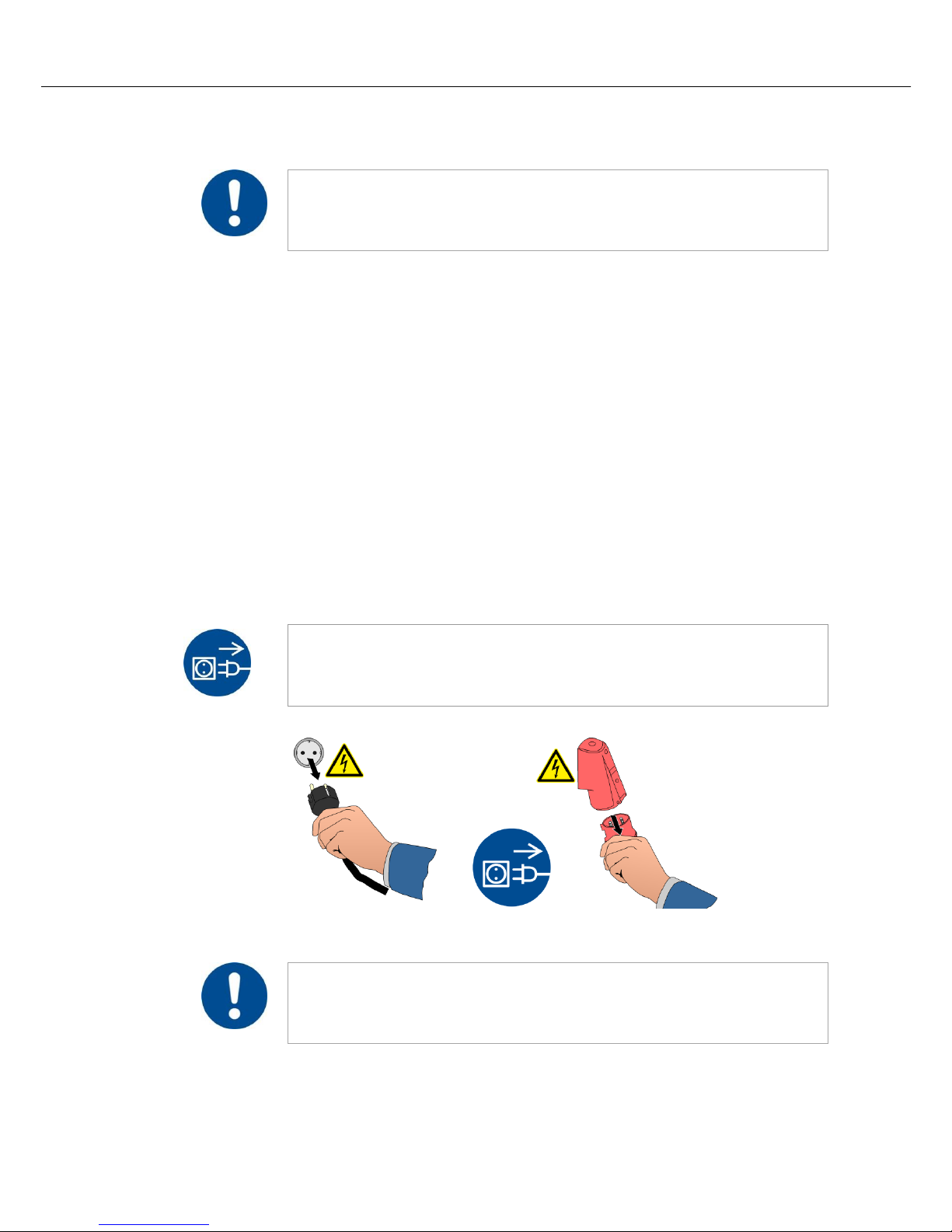
Note
The power plug is to be pulled out to stop the furnace in case of an emergency.
Therefore, the power plug must be accessible at all times when the furnace is operating so
that it can be pulled out quickly in case of an emergency.
Pos: 84 /TD/Sicherheit/Grundlegende Maß nahmen im Notfall - Netzstecker ziehen ( alle Anleitungen) - Grafik @ 36\mod_1 360079722854_51.docx @ 208920 @ @ 1
Fig. 6: Pull the power plug (similar to picture)
Pos: 85 /TD/Allgemeine Hinweise (für alle Anleitungen)/Warnung - Bei unerwarteten Vorgänge n im Ofen (z.B. starke Rauchentwicklung oder Geruchsbelästigung) @ 4\mod_1 205306579737_51.docx @ 34218 @ @ 1
Risks during Normal Operation!
Switch the furnace off immediately in case of unexpected occurrences in the furnace (e.g.
a lot of smoke or unusual smells). Wait until the furnace has cooled naturally to room
temperature.
Page 21
21
Pos: 86 /TD/Allgemeine Hinweise (für alle Anleitungen)/Warnung - Bei unerwartet en Vorgängen darf der Ofen nicht geöffnet ...- Grafik Top_HO_F (Modell 2015) @ 1 04\mod_1444049593859_51.docx @ 412601 @ @ 1
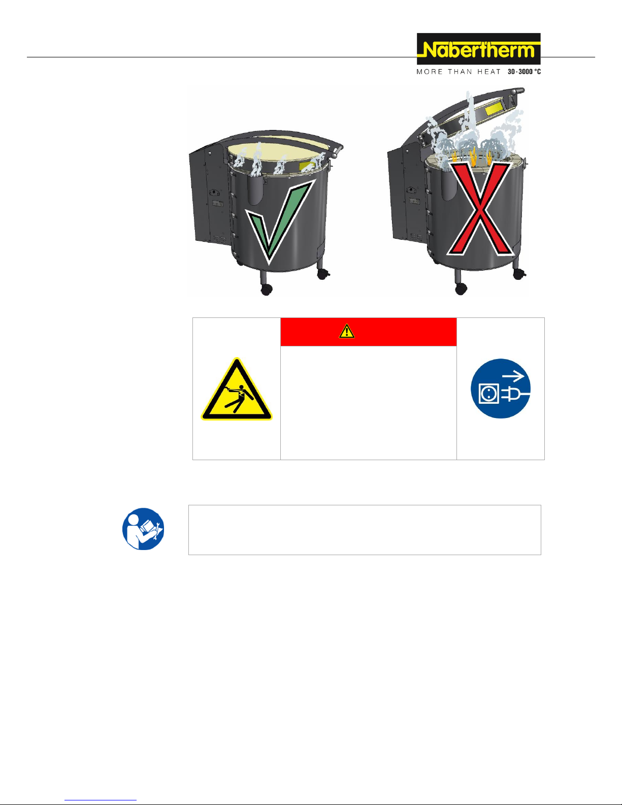
In case of fire, keep
lid closed.
Immediately remove
the power plug.
Keep doors and
windows closed. This
prevents smoke
spreading.
Immediately notify
the fire service,
regardless of the
extent of the fire.
When you phone the
fire service, remain
calm and speak
clearly.
Pos: 87 /TD/Sicherheit/Sicherheitssymbole/ Warnhinweise-ISO-ANSI/Warnsymbol_ Gefahr - Elektrischer Schlag - Piktogram m elektr. Schlag - Netzstecker ziehen @ 9\ mod_1247472185096_51.docx @ 6 3063 @ @ 1
DANGER
• Danger of electric shock.
• Risk of fatal injury.
• Work on electrical
equipment may be carried out only by
qualified electricians
or by trained personnel authorized by
Nabertherm.
• Before starting work, pull out the
power plug
Pos: 88 /TD/Sicherheit/Überschrift - Grun dlegende Maßnahmen bei Wartung und Ins tandhaltung @ 0\mod_116782606062 0_51.docx @ 5193 @ 2 @ 1
3.7 Basic Measures for Servicing and Maintenance
Pos: 89 /TD/Sicherheit/Grundlegende Maß nahmen bei Wartung und Instandhaltung T op, HO und F - Öfen @ 13\mod_1291 107854956_51.docx @ 109556 @ @ 1
Maintenance work must be performed by authorized persons, following the maintenance
instructions and the accident prevention regulations. We recommend that the maintenance
and repair work be carried out by the service team of Nabertherm GmbH. Noncompliance may cause injuries, death, or considerable damage to property.
Switch the furnace off at the power supply and pull out the plug.
The furnace must be completely empty.
When cleaning furnaces, control cabinets, or electrical equipment housings, never spray
them with water.
When maintenance or repair work has been completed, before recommencing production
ensure the following:
Check that loosened screw connections/tensioning straps have been re-tightened,
Reinstall protective equipment, screens, and filters If applicable),
Remove all material, tools, and other equipment used for the maintenance or repair
work from the working area of the furnace,
Power cables may be replaced only with similar, approved cables.
Page 22
22
Pos: 90 /TD/Sicherheit/Überschrift - Allge meine Gefahren an der Anlage @ 0\m od_1168596796288_51.docx @ 6014 @ 2 @ 1
3.8 General Risks with the Furnace
Pos: 91 /TD/Sicherheit/Allgemeine Gefahren ( Verbrennung, Quetschen, Strom) - T op, HO und F @ 13\mod_12894667661 04_51.docx @ 107663 @ @ 1
• Bypass connection/exhaust air pipe/lid/handle all become hot when the furnace is
operating.
• Danger of burning.
• Do NOT touch the bypass connection/exhaust air pipe/lid/handle when the furnace is
operating.
• Do not insert objects into the openings in the furnace housing, the exhaust air holes
or the cooling slits of the switchgear or the furnace.
• Danger of electric shock.
• Do NOT insert any objects.
• Danger of electric shock
• Risk of fatal injury
• The furnace must NOT become wet during operation or maintenance
• Danger of explosion from materials in the furnace
• Risk of fatal injury
• Do NOT insert explosive substances into the furnace when it has reached its operating
temperature.
• NO explosive dusts or solvent-air mixtures inside the furnace.
• Do NOT operate the furnace in areas where there is a risk of explosion.
• NO explosive dusts or solvent-air mixtures in the surrounding area.
• Fire hazard if an extension cable is used
• Risk of fatal injury
With 230 V furnace models make sure that:
• The distance between the circuit breaker and the power socket that the furnace is
connected to
is as short as possible.
• NO power board or extension cable is used between the power socket and the
furnace.
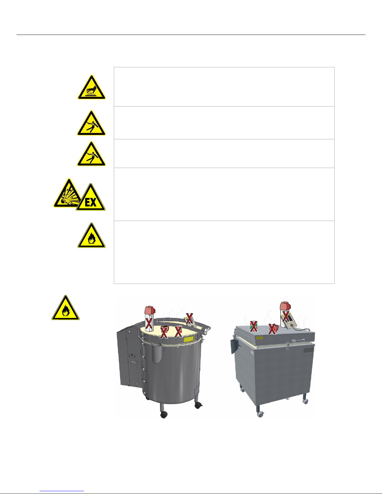
Pos: 92 /TD/Sicherheit/Warnung - Es dürfen keine Gegenstände auf dem To p-HO und F Ofen abgelegt/abgestellt - Grafi k @ 104\mod_1444052645305_51.doc x @ 412627 @ @ 1
Risks during normal
operation
Do not place objects
on top of the furnace.
There is a risk of fire
or explosion.
Page 23
23
Pos: 93 /TD/Transport_Montage_Inbetrieb nahme/Erstinbetriebnahme/Überschrift - Tr ansport, Montage und Erstinbetriebn ahme @ 0\mod_1158844227416_51.doc x @ 3112 @ 1 @ 1
4 Transportation, Installation and Initial Start-Up
Pos: 94 /TD/Transport_Montage_Inbetrieb nahme/Erstinbetriebnahme/Überschrift - Anlieferung @ 0\mod_1167826534889_ 51.docx @ 5220 @ 2 @ 1
4.1 Delivery
Pos: 95 /TD/Transport_Montage_Inbetrieb nahme/Erstinbetriebnahme/Anlieferung T op, HO und F Öfen - (Hinweise allgemein) @ 13\mod_1289468478869_51.docx @ 1076 86 @ @ 1
Check that everything is complete
Compare the delivered items with the delivery note and the purchase order documents.
Immediately notify the carrier and Nabertherm GmbH of any missing or damaged parts, as
complaints at a later date cannot be acknowledged.
Danger of injury
When the furnace is being lifted, parts of the furnace or the furnace itself could topple over,
slip, or fall. Before the furnace is lifted, make sure no one is in the working area.
Appropriate protective gloves must be worn.
Safety Instructions
Industrial trucks (e.g.: crane/pallet truck) must be operated only by authorized
personnel. The operator bears sole responsibility for safe operation and the load.
Use only lifting equipment with sufficient load-bearing capacity.
When the furnace is being lifted, make sure that the ends of the forks or the load do
not catch on neighboring goods. Use a crane to move tall parts, such as control
cabinets.
Lifting gear must be attached only to positions that have been designated for this
purpose.
Attachments, piping, or cable conduits must never be used to affix lifting gear.
Attach transportation equipment only to positions intended for this purpose.
Note
Wear protective gloves when installing the furnace.
Risks during normal operation
Suspended loads are dangerous. Working beneath a suspended load is prohibited. There is
a risk of fatal injury.
Note
Safety and accident prevention guidelines applicable for forklift trucks must be followed.
Pos: 96 /TD/Transport_Montage_Inbetrieb nahme/Erstinbetriebnahme/Anlieferung - Öfen mit einem Hubwagen transportier en @ 2\mod_1184672460200_51.docx @ 20000 @ @ 1
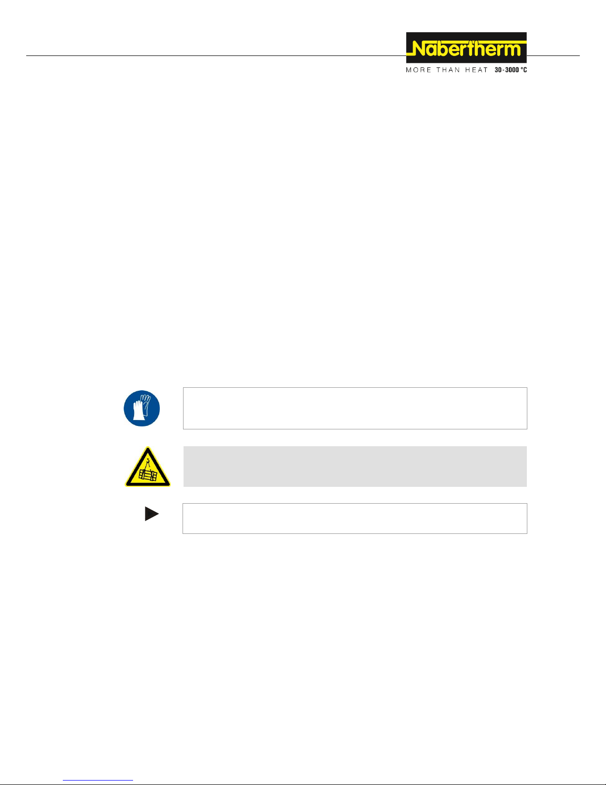
Transportation with a Pallet Truck
Observe the maximum permitted capacity of the pallet truck.
1. Our furnaces are delivered ex works on wooden frames to facilitate unloading.
Transport the furnace in its original packaging and with suitable equipment to
prevent any damage. Remove the packaging only when the furnace is in its final
location. When transporting the furnace, make sure it is secured against sliding,
toppling over, and damage. The furnace should be transported and installed by at
least two persons. Do not store the furnace in damp rooms or outdoors.
2. Push the pallet truck underneath the transportation frame. Make sure that the pallet
truck is completely beneath the frame. Pay attention to neighboring goods.
Page 24
24
Fig. 7: Pallet truck is pushed completely beneath the transportation frame
3. Lift the furnace carefully and pay attention to its center of gravity. When the furnace
is being lifted, make sure that the ends of the forks or the load do not catch on
neighboring goods.
4. Make sure that the furnace is balanced safely; if not, attach securing equipment.
Push the furnace carefully, slowly and with the pallet truck at its lowest position. Do
not transport the furnace on inclines.
5. Carefully lower the furnace at its final position. Pay attention to neighboring goods.
Try not to set it down too abruptly.
Pos: 97 /TD/Sicherheit/Sicherheitssymbol e/Warnhinweise-ISO-ANSI/Warnsymbol_ Vorsicht - Rutschen/Kippen des Gerätes - Piktogramm Kippen/Heben/Anheben @ 9\mod_1247064081950_51.docx @ 62 955 @ @ 1
CAUTION
• Device may slip or topple over.
• Damage to the device.
• Risk of injury from lifting
heavy loads.
• Transport device only in original
packaging.
• Several people must carry the device.
Pos: 98 /TD/Transport_Montage_Inbetrieb nahme/Erstinbetriebnahme/Überschrift - Auspacken @ 2\mod_118473951798 5_51.docx @ 20013 @ 2 @ 1
4.2 Unpacking
Pos: 99 /TD/Allgemeine Hinweise (für alle Anleitungen)/Hinweis - Allgemeiner Hi nweis zur Verpackung (z.B. Laboröfen) @ 3\mod_1192437185846_51.docx @ 235 09 @ @ 1
Note
The furnace packaging prevents damage during transportation. Make sure that you
remove all packaging material (also inside the Furnace Chamber). Keep the packaging
and transportation securing equipment in case it is needed for future transportation or
storage.
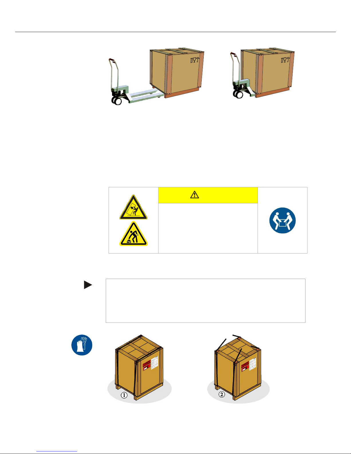
At least two people are needed to carry/transport the furnace, more for larger furnaces.
Pos: 100 /TD/Transport_Montage_Inbetrie bnahme/Erstinbetriebnahme/Auspacken Troc kenschrank TR ... - Teil 1 @ 9\ mod_1246978000133_51.docx @ 62643 @ @ 1
Wear protective
gloves
Page 25

25
1. Check the transportation packaging for any signs of damage.
2. Remove straps from the transportation packaging.
3. Loosen the screws and remove the wooden frame from the cardboard box (if
applicable)
Pos: 101 /TD/Transport_Montage_Inbetrie bnahme/Erstinbetriebnahme/Auspacken To p und F Öfen - Teil 2 @ 156\mod_1 494510779792_51.docx @ 643026 @ @ 1
4. Carefully lift the cardboard box and remove it from the pallet. Compare the
delivered items with the delivery note and the order documents, see "Delivery".
5. The pallet contains a packaging unit for accessories (Example: power cable, bypass
connection, ceramic shelves, castors and tools to assemble the castors and the bypass
connection).
6. Remove the top protective film (A) from the furnace.
7. To carry the furnace, place your hands beneath the furnace on the side (near the feet)
and make sure that you have a good grip. Wear protective gloves when installing
the furnace. Keeping your back straight, lift the furnace from the pallet and
Page 26

26
carefully lower it at the point where it is to be installed. The furnace should be
transported by at least 2 people.
8. Remove the protective film that protects the insulation between the furnace and the
lid. (A) Make sure that you remove all the packaging material. Keep the packaging
and transportation securing material (if applicable) in case it is needed for future
transportation or storage of the furnace.
Pos: 102 /TD/Sicherheit/Sicherheitssymbol e/Warnhinweise-ISO-ANSI/Warnsymbol _Vorsicht - Rutschen/Kippen des Geräte s - Piktogramm Kippen/Heben/Anheben @ 9\mod_1247064081950_51.docx @ 6 2955 @ @ 1
CAUTION
• Device may slip or topple over.
• Damage to the device.
• Risk of injury from lifting
heavy loads.
• Transport device only in original
packaging.
• Several people must carry the device.
Pos: 103 /TD/Transport_Montage_Inbetrie bnahme/Erstinbetriebnahme/Überschrift - Transportsicherung/Verpackung @ 0\m od_1167826775847_51.docx @ 5229 @ 2 @ 1
4.3 Transport Securing Device/Packaging
Pos: 104 /TD/Transport_Montage_Inbetrie bnahme/Erstinbetriebnahme/Verpackung - Allgemeine Hinweise zur Verpackung - keine spezielle Transportsicherung @ 1\ mod_1171004073117_51.docx @ 9 153 @ @ 1
Note
No special transportation securing equipment is available for this furnace
The furnace packaging prevents damage during transportation. Make sure that you remove
all packaging material (also inside the Furnace Chamber). All packaging material can be
recycled. The packaging was designed so that no special description is necessary.
Pos: 105 /TD/Transport_Montage_Inbetrie bnahme/Erstinbetriebnahme/Verpackung - Allgemeine Hinweise zur Verpackung - Kinder und Verpackungsmaterial @ 13\mod_ 1290686355811_51.docx @ 109504 @ @ 1
Safety Information
Do not allow children to play with packaging parts. They are at risk of suffocation from
folding boxes and plastic film.
Pos: 106 /TD/Transport_Montage_Inbetrie bnahme/Erstinbetriebnahme/Überschrift - Bauliche- und Anschlussvoraussetzu ngen @ 0\mod_1167826890943_51.docx @ 5238 @ 2 @ 1
4.4 Constructional and Connection Requirements
Pos: 107 /TD/Transport_Montage_Inbetrie bnahme/Erstinbetriebnahme/Überschrift - Aufstellung (Standort des Ofens) @ 2\ mod_1184848718972_51.docx @ 20166 @ 3 @ 1
4.4.1 Installation (Furnace Location)
Pos: 108 /TD/Transport_Montage_Inbetrie bnahme/Erstinbetriebnahme/Standort ein es Top, HO und F - Ofens @ 13\mod_1 289479898145_51.docx @ 107732 @ @ 1
When the furnace is being installed, these safety instructions must be followed:
The furnace must be installed in a dry room as stated in the safety instructions.
Page 27

27
The surface (floor or bench) where the furnace is to be installed must be level to
permit the furnace to stand upright. Place the furnace on a non flammable surface
(fire safety class A DIN 4102 – Example: concrete, tiles, glass, aluminum or steel) so
that any hot material falling from the furnace cannot ignite the surface.
The load-bearing capacity of the bench (e.g. bench-top model Top 16/R) must be
sufficient to take the weight of the furnace and accessories.
Non-flammable surface
Top 16/R Bench (accessory)
Fig. 8: Example: Non flammable surface (similar to picture)
In spite of its good insulation, the furnace radiates heat from its outer surfaces. If
necessary, this heat must be dissipated (contact a ventilation engineer if necessary).
Flammable materials must be kept at least 0.5 m (safety distance S) away from the
furnace. In some cases, the distance must be greater because of specific local conditions.
The minimum distance between the furnace and non-flammable materials may be reduced
to 0.2 m at the sides. If the charge emits gases or vapors, ensure adequate ventilation at the
installation site and/or a suitable exhaust air venting system. If required, the customer must
provide a suitable vent for combustion exhaust gases.
Fig. 9: Minimum safety distance to flammable materials (similar to picture)
Pos: 109 /TD/Sicherheit/Sicherheitssymbol e/Warnhinweise-ISO-ANSI/Warnsymbol _Gefahr - Brandgefahr - Piktogramm Br andgefahr @ 9\mod_1247148035738_5 1.docx @ 63010 @ @ 1
DANGER
• Risk of fire, danger to health
• Risk of fatal injury
• Adequate ventilation must be ensured at the
installation location to remove exhaust heat and exhaust gases
Page 28

28
Pos: 110 /TD/Allgemeine Hinweise (für alle A nleitungen)/Hinweis - Vor Inbetriebna hme des Ofens sollte dieser 24 Stunden am Aufstellungsort akklimatisiert .. @ 3\m od_1195568014336_51.docx @ 2787 1 @ @ 1
Note
Before starting the furnace for the first time, allow it to acclimatize at its installation
location for 24 hours.
Pos: 111 /TD/Sicherheit/Sicherheitssymbol e/Warnhinweise-ISO-ANSI/Warnsymbol _Gefahr - Gefahren durch automatisch e Löscheinrichtungen (Wasser_Löschgas) @ 55\mod_1391587048048_51.docx @ 269740 @ @ 1
DANGER
• Danger associated with the use of an automatic extinguishing
system
• Danger to life from electrocution through wetness,
suffocation caused by extinguishing gas, etc.
• If automatic extinguishing systems are in place to fight fires and
protect the building, e.g. sprinkler systems, care must be taken
during their planning and installation that no additional hazards are
created, for example by extinguishing a pilot light, mixing
hardening oil and extinguishing water, shutdown of electrical
equipment, etc.
Pos: 112 /TD/Transport_Montage_Inbetrie bnahme/Erstinbetriebnahme/Überschrift - Montage, Installation und Anschluss @ 0\mod_1167827976269_51.docx @ 5 292 @ 2 @ 1
4.5 Assembly, Installation, and Connection
Pos: 113 /TD/Transport_Montage_Inbetrie bnahme/Erstinbetriebnahme/Überschrift - Montage der Untergestellerhöhung (Zub ehör-Untergestellerhöhung) @ 13\ mod_1290432714317_51.docx @ 108766 @ 3 @ 1
4.5.1 Assembling the Base Extension (Accessory)
Pos: 114 /TD/Transport_Montage_Inbetrie bnahme/Erstinbetriebnahme/Überschrift - Untergestellerhöhung Fusing-Toplad er Modell F … (Ei nzug Mitte) @ 156\mod_149 4576617483_51.docx @ 643166 @ @ 1
Base Extension for Fusing Top Loader Model F …
Pos: 115 /TD/Transport_Montage_Inbetrie bnahme/Erstinbetriebnahme/Das als Zube hör enthaltene Untergestell aus der Verpac kungseinheit entnehmen und Einzel teile mit der @ 156\mod_149457688399 5_51.docx @ 643218 @ @ 1
Remove the base from the packaging and compare the parts with the list below.
Pos: 116 /TD/Transport_Montage_Inbetrie bnahme/Erstinbetriebnahme/Einzelteile d es Untergestells - (Toplader Modell F) - T abelle @ 156\mod_1494576888683_51. docx @ 643244 @ @ 1
No.
Quantity
Name
1
2
Brace, long
2
2
Brace, short
3
4
Feet with castors, two with locking brake
4
8
Collar screw M8
5
1
Open-end wrench
Pos: 117 /TD/Transport_Montage_Inbetrie bnahme/Erstinbetriebnahme/Einzelteile d es Untergestells - (Toplader Modell F) - Grafik @ 156\mod_1494576893167_51. docx @ 643270 @ @ 1
Fig. 10: Parts of the base (similar to picture)
Pos: 118 /TD/Transport_Montage_Inbetrie bnahme/Erstinbetriebnahme/Einen Fuß (3) mit zwei Schrauben (4) (mit je einer lang en (1) und einer kurzen (2) Strebe) m ontieren @ 156\mod_1494576898855_5 1.docx @ 643296 @ @ 1
Assemble one foot (3) with two screws (4) (with one long (1) and one short (2) brace).
Loosely tighten the screws with the supplied tool (5).
Pos: 119 /TD/Transport_Montage_Inbetrie bnahme/Erstinbetriebnahme/Umlaufend di e anderen Füße und Streben ergänzen. Bei Montage aller Füße und Streben Sc hrauben fest @ 156\mod_14945769 04746_51.docx @ 643322 @ @ 1
Assemble the other feet and braces. When all the feet and braces are assembled,
tighten the screws.
1
2
3
4
5
Page 29

29
Pos: 120 /TD/Transport_Montage_Inbetrie bnahme/Erstinbetriebnahme/Es sind die vorh er gelösten Transportrollen unter die F üße zu montieren (siehe Kapitel „M ontage der @ 15 6\mod_14945 83567113_51.docx @ 643798 @ @ 1
Screw the castors that you removed on to the bottom of the feet (see “Assembling the
Castors”).
Pos: 121 /TD/Transport_Montage_Inbetrie bnahme/Erstinbetriebnahme/Ofen vorsichtig auf das Gestell stellen. Schutzhandsc huhe tragen und den Ofen nur von der Bodenun.. @ 156\mod_149457695631 1_51.docx @ 643374 @ @ 1
Carefully place the furnace on to the frame. Wear protective gloves and lift the
furnace only by the base. At least two people are needed to lift the furnace, more for
heavier furnaces.
Pos: 122 /TD/Transport_Montage_Inbetrie bnahme/Erstinbetriebnahme/Überschrift - Untergestellerhöhung Toplader Modell T op … (Einzug Mi tte) @ 156\ mod_1494576650581_51.docx @ 643 192 @ @ 1
Base Extension Top Loader Model Top …
Pos: 123 /TD/Transport_Montage_Inbetrie bnahme/Erstinbetriebnahme/Das als Zu behör enthaltene Untergestell aus der Verpac kungseinheit entnehmen und Einzel teile mit der @ 156\mod_149457688399 5_51.docx @ 643218 @ @ 1
Remove the base from the packaging and compare the parts with the list below.
Pos: 124 /TD/Transport_Montage_Inbetrie bnahme/Erstinbetriebnahme/Einzelteile d es Untergestells - (Modell Top) - Tabell e @ 156\mod_1494577363935_51.doc x @ 643436 @ @ 1
No.
Quantity
Name
3
2
Base extension Top 45/Top 60
Pos: 125 /TD/Transport_Montage_Inbetrie bnahme/Erstinbetriebnahme/Montage der U ntergestellerhöhung (gesteckte Version) - (Modell Top) - Grafik @ 156\mod_ 1494583436720_51.docx @ 643772 @ @ 1
Fig. 11: Assembling the base extension (similar to picture)
Pos: 126 /TD/Transport_Montage_Inbetrie bnahme/Erstinbetriebnahme/Transportroll en (1) durch kräftiges ziehen nach unten lös en. @ 157\mod_1495005522554_5 1.docx @ 645291 @ @ 1
To remove the castors (1) pull them firmly downwards.
Pos: 127 /TD/Transport_Montage_Inbetrie bnahme/Erstinbetriebnahme/Hülsen (2) (befi ndlich an den Füßen des Ofens) mit zu m Beispiel einem breiten Flachschra ubendreher @ 156\mod_1494577377404 _51.docx @ 643514 @ @ 1
Carefully loosen the sleeves (2) (on the furnace feet) with a wide screwdriver and
hammer for example.
Pos: 128 /TD/Transport_Montage_Inbetrie bnahme/Erstinbetriebnahme/Beide Unterge stellerhöhungen (3) auf die Füße des Of ens aufstecken. Auf festen Sitz der Unt ergeste.. @ 156\mod_1494577382138 _51.docx @ 643540 @ @ 1
Insert the two base extensions (3) on to the furnace feet. Make sure that the base
extension sits firmly.
Pos: 129 /TD/Transport_Montage_Inbetrie bnahme/Erstinbetriebnahme/Es sind die vorh er gelösten Transportrollen unter die F üße zu montieren (siehe Kapitel „M ontage der @ 15 6\mod_14945 83567113_51.docx @ 643798 @ @ 1
Screw the castors that you removed on to the bottom of the feet (see “Assembling the
Castors”).
Pos: 130 /TD/Transport_Montage_Inbetrie bnahme/Erstinbetriebnahme/Überschrift - Montage der Transportrollen @ 13\ mod_1289819020312_51.docx @ 107922 @ 3 @ 1
4.5.2 Assembling the Castors
Pos: 131 /TD/Transport_Montage_Inbetrie bnahme/Erstinbetriebnahme/Die im Liefer umfang befindlichen Transportrollen sind bz w. können wenn erforderlich an de n Füßen des @ 156\mod_14943330072 43_51.docx @ 642306 @ @ 1
If required, the castors that are delivered can be attached to the furnace feet. We
recommend that the castors with the locking brake are attached to the front of the furnace.
The number of castors depends on the number of feet and varies depending on the furnace
model. Furnace model Top 16/R (bench-top model) is delivered without castors. Wear
protective gloves when assembling the castors or when lifting the furnace. Only lift the
furnace from the base. The furnace must NOT be placed on its side, as this will damage
the insulation and heating elements and thus destroy the furnace. Nabertherm accepts
no liability for damage resulting from assembly of the castors.
Pos: 132 /TD/Transport_Montage_Inbetrie bnahme/Erstinbetriebnahme/Die im Liefer umfang enthaltenen Transportrollen kö nnen bei Bedarf unter die Füße des Ofens ges teckt @ 156\mod_1494583 860722_51.docx @ 643824 @ @ 1
If required, the supplied castors can be inserted under the feet of the furnace.
Page 30

30
Pos: 133 /TD/Transport_Montage_Inbetrie bnahme/Erstinbetriebnahme/Montage der Tr ansportrollen - (gesteckte Version) - Grafik @ 156\mod_1494584108353_5 1.docx @ 643850 @ @ 1
Fig. 12: Assembling the castors (similar to picture)
Pos: 134 /TD/Transport_Montage_Inbetrie bnahme/Erstinbetriebnahme/Überschrift - Montageempfehlung (Einzug Mitte) @ 1 56\mod_1494336748973_51.docx @ 642388 @ @ 1
Assembly recommendation
Pos: 135 /TD/Transport_Montage_Inbetrie bnahme/Erstinbetriebnahme/Die Einhaltu ng der Empfehlungen entbinden den Ver wender unserer Produkte nicht vom eigen verantwort.. @ 156\mod_149433675 3286_51.docx @ 642414 @ @ 1
Compliance with our recommendations does not release users of our products from their
personal responsibly in relation to local situations and conditions. However, several general
recommendations should be considered:
Pos: 136 /TD/Transport_Montage_Inbetrie bnahme/Erstinbetriebnahme/Bei Öfen bis 60 kg empfehlen wir den Ofen vorsichtig üb er die Ofenfüße zu kippen. Fassen Sie ... @ 156\mod_1494336757739_51.d ocx @ 642440 @ @ 1
In the case of furnaces up to 60 kg we recommend that you tip the furnace carefully
on its feet. Grip below the furnace (1) and carefully tip it to the side. Assemble the
first castor and then carefully release your grip on the furnace. Repeat this process for
all the castors. We recommend that a second person prevents the furnace from tipping
too much, falling over or rolling away.(3)/(4).
Pos: 137 /TD/Transport_Montage_Inbetrie bnahme/Erstinbetriebnahme/Montag e der Transportrollen bei Öfen bis 60 kg - Gra fik @ 156\mod_1494336762208_51.d ocx @ 642466 @ @ 1
Fig. 13: Example: Assembling castors on furnaces up to 60 kg (similar to picture)
Pos: 138 /TD/Transport_Montage_Inbetrie bnahme/Erstinbetriebnahme/Öfen über 60 kg dürfen NICHT über die Ofenfüße ge kippt werden. Es besteht die Gefahr, dass beim ... @ 156\mod_1494584214721_ 51.docx @ 643876 @ @ 1
Do NOT tip furnaces above 60 kg on their feet. There is a risk of the feet “breaking
off” if you tip the furnace. To insert the castors, we recommend that you sit the
furnace on four suitable wooden blocks. These blocks should be at least 20 cm high so
that the castors can be screwed beneath the feet. At least two people are needed to lift
the furnace, more for heavier furnaces.
Pos: 139 /TD/Transport_Montage_Inbetrie bnahme/Erstinbetriebnahme/Montage der Tr ansportrollen bei Öfen ab 60 kg - Gr afik @ 156\mod_1494336771021_51.doc x @ 642518 @ @ 1
A = min. 20 cm
Furnace base from below
Fig. 14: Example: Assembling castors on furnaces over 60 kg (similar to picture)
Pos: 140 /TD/Transport_Montage_Inbetrie bnahme/Erstinbetriebnahme/Nach dem A usrichten des Ofens sind die Feststellbremse n der Transportrollen zu sichern. @ 156\mod_1494336775411_51.docx @ 6 42544 @ @ 1
When the furnace is in position, lock the brakes on the castors.
1
2
3
4
Page 31

31
Pos: 141 /TD/Transport_Montage_Inbetrie bnahme/Erstinbetriebnahme/Nach Montage des Bypass-Stutzens und Ausrichtu ng des Ofens, kann wenn erforderlich ein e Abgasführung @ 156\mod_14943368 27819_51.docx @ 642570 @ @ 1
When the bypass connection has been attached to and aligned on the furnace, you can then
assemble an exhaust gas system if this is required. See "Exhaust Gas System" for more
information about exhaust gas.
Pos: 142 /TD/Transport_Montage_Inbetrie bnahme/Erstinbetriebnahme/Überschrift - Montage des Controllers (modellabhängig ) @ 51\mod_1386605366661_51.d ocx @ 257500 @ 3 @ 1
4.5.3 Assembling the Controller (Depending on the Model)
Pos: 143 /TD/Transport_Montage_Inbetrie bnahme/Erstinbetriebnahme/Controller_B0 1 - Der im Lieferumfang befindliche H alter des Controllers (modellabhängig ) ist am ... @ 104\mod_1444203310032_5 1.docx @ 412813 @ @ 1
Attach the supplied controller with holder (model-related) to the furnace.
Pos: 144 /TD/Transport_Montage_Inbetrie bnahme/Erstinbetriebnahme/Controller_B0 2 - An der Position des Controllers b efinden sich Schrauben (1) zur Montage d es Halters @ 104\mod_1444203435587 _51.docx @ 412839 @ @ 1
At the controller position there are screws to attach the holder; these must be unscrewed
beforehand.
Pos: 145 /TD/Transport_Montage_Inbetrie bnahme/Erstinbetriebnahme/Controller_B0 3 - Halter mit den vorher gelösten Sc hrauben am Ofen auf richtige Position setzen und @ 104\mod_144420358084 8_51.docx @ 412865 @ @ 1
Place the controller holder (2) with the screws loosened on to the correct position on the
furnace and fasten it with suitable tools (3).
Pos: 146 /TD/Transport_Montage_Inbetrie bnahme/Erstinbetriebnahme/Controller_B0 4 - Montage des Halters an das Ofeng ehäuse_Controller einsetzen - Grafik @ 104\mod_1444203746764_51.docx @ 4 12891 @ @ 1
Fig. 15: Install the holder on the furnace housing (similar to picture)
Pos: 147 /TD/Transport_Montage_Inbetrie bnahme/Erstinbetriebnahme/Controller_B0 5 - Schrauben des Halters fest a nziehen und auf sicheren Halt überprüfen @ 104\mod_1444204784863_51.docx @ 412917 @ @ 1
Tighten the screws (3) of the holder and check that is sits properly (4).
Pos: 148 /TD/Transport_Montage_Inbetrie bnahme/Erstinbetriebnahme/Controller_B0 6 - Schrauben des Halters fest anzie hen - Grafik @ 104\mod_1444205028724_ 51.docx @ 412943 @ @ 1
Fig. 16: Tighten the screws on the holder (similar to picture)
Pos: 149 /TD/Transport_Montage_Inbetrie bnahme/Erstinbetriebnahme/Controller_C 01 - Der Controller ist an dem Ofen be findlichen Halter einzusetzen @ 103\m od_1442499950347_51.docx @ 409670 @ @ 1
Place the controller in the holder on the furnace.
Page 32

32
Pos: 150 /TD/Transport_Montage_Inbetrie bnahme/Erstinbetriebnahme/Controller_B0 7 -Controller in die befindliche Halter ung einsetzen - TOP_F-HO - Grafik @ 10 4\mod_1444209154288_51.docx @ 412 969 @ @ 1
Fig. 17: Place the controller in the holder (similar to picture)
Pos: 151 /TD/Transport_Montage_Inbetrie bnahme/Erstinbetriebnahme/Überschrift - Controller in den am Ofen befindlichen H alter einsetzen (modellabhängig) @ 1 03\mod_1442497493540_51.docx @ 40 9566 @ 3 @ 1
4.5.4 Place the Controller in the Holder on the Furnace (model-related)
Pos: 152 /TD/Transport_Montage_Inbetrie bnahme/Erstinbetriebnahme/Controller_C 02 - Achten Sie darauf, dass der Contr oller vollständig in die befindliche Halteru ng ... @ 103\mod_1442497835549_51.d ocx @ 409592 @ @ 1
Make sure that the controller is placed correctly in the holder. If this is ignored, the
controller may be damaged or destroyed. Nabertherm accepts no liability if the controller is
not handled properly.
Pos: 153 /TD/Transport_Montage_Inbetrie bnahme/Erstinbetriebnahme/Controller_C 03 - Controller in den am Ofen befindlic hen Halter einsetzen - Grafik @ 103\mo d_1442498084763_51.docx @ 409618 @ @ 1
Fig. 18: Place the controller in the holder on the furnace (similar to the picture)
Pos: 154 /TD/Betrieb_Bedienung/Controll er/B400/B410/C440/C450/P470/P480/Hand habung des Controllers_B400/C440/P470 _Controller mit Halterung - Text @ 9 2\mod_1431087782050_51.docx @ 380 396 @ @ 1
The controller can simply be removed from the holder for especially ergonomic handling
and more comfortable operation.
Pos: 155 /TD/Transport_Montage_Inbetrie bnahme/Erstinbetriebnahme/Überschrift - Montage des Bypass-Stutzens @ 13 \mod_1289811687101_51.docx @ 1 07876 @ 3 @ 1
4.5.5 Assembling the Bypass Connection
Pos: 156 /TD/Transport_Montage_Inbetrie bnahme/Erstinbetriebnahme/Der im Lieferum fang befindliche Bypass-Stutzen ist seitlich am Ofen zu befestigen. Öfen der M odell.. @ 156\mod_1494404295552_51.docx @ 642686 @ @ 1
The bypass connection that is part of the delivery is fixed to the side of the furnace.
Furnaces in the top loader F series… have no bypass connection. Furnace model Top 16/R
is delivered without a bypass connection. This model is ventilated via a hole in the middle
of the lid.
Pos: 157 /TD/Transport_Montage_Inbetrie bnahme/Erstinbetriebnahme/An der Positio n des Bypass-Stutzens befinden sic h zwei Schrauben (1) zur Montage des Bypa ss-... @ 156\mod_1494404374337_5 1.docx @ 642712 @ @ 1
At the position where the bypass connection is fixed are two screws (1) to assemble it;
these must be removed beforehand.
Pos: 158 /TD/Transport_Montage_Inbetrie bnahme/Erstinbetriebnahme/Bypass-St utzen (2) mit den vorher gelösten Schrau ben seitlich am Ofen auf richtige Positi on set.. @ 156\mod_1494404380243_51.doc x @ 642738 @ @ 1
Place the bypass connection (2) with the screws on to the correct position on the side of the
furnace and fix it with suitable tools.
Page 33

33
Pos: 159 /TD/Transport_Montage_Inbetrie bnahme/Erstinbetriebnahme/Montage des Bypass-Stutzens - Top-Ofen - Grafik @ 156\mod_1494404384556_51.docx @ 6 42764 @ @ 1
Fig. 19: Assembling the bypass connection (similar to picture)
Pos: 160 /TD/Transport_Montage_Inbetrie bnahme/Erstinbetriebnahme/Nach Montage des Bypass-Stutzens und Ausrichtu ng des Ofens, kann wenn erforderlich ein e Abgasführung @ 156\mod_14943368 27819_51.docx @ 642570 @ @ 1
When the bypass connection has been attached to and aligned on the furnace, you can then
assemble an exhaust gas system if this is required. See "Exhaust Gas System" for more
information about exhaust gas.
Pos: 161 /TD/Transport_Montage_Inbetrie bnahme/Erstinbetriebnahme/Montage der Abluftverrohrung an den Bypass-St utzen - Top-Ofen - Grafik @ 156\mod_ 1494404396353_51.docx @ 642816 @ @ 1
1 Assembling the exhaust air piping: If required, see "Exhaust Gas System"
2 Bypass connection
Fig. 20: Assembling the exhaust gas piping on the bypass connection (similar to picture)
Pos: 162 /TD/Transport_Montage_Inbetrie bnahme/Erstinbetriebnahme/Überschrift - 1.1.1 Abluftführung @ 0\mod_116782 8513042_51.docx @ 5310 @ 3 @ 1
4.5.6 Venting Exhaust Fumes
Pos: 163 /TD/Transport_Montage_Inbetrie bnahme/Erstinbetriebnahme/Abgasführung beim Top, HO und F - Öfen allgemein er Text @ 13\mod_1289490231021_51. docx @ 107755 @ @ 1
When ceramics are fired, depending on the quality of the clay and/or glaze, they can emit
gases and vapors that are harmful to your health. It is therefore necessary to make sure that
the "exhaust gases" emitted from the exhaust air opening are directed outdoors in a suitable
manner (ventilate the working area). If adequate ventilation cannot be ensured at the
working area, the "exhaust gases" must be removed via a pipe. We recommend that you
connect a pipe to the furnace to remove the exhaust gases.
A suitable metal exhaust gas pipe with NW80 can be used to vent the gases. Use only metal
pipes (example: stainless steel). The pipe must be attached facing upwards and be fixed to
the wall or ceiling. Adequate room ventilation is needed to achieve the bypass effect.
Vapors may not be extracted through a fan.
Assume a maximum exhaust gas temperature of approx. 200 °C (392 °F) for the piping
system. There is a risk of burning at the bypass connection and the piping. Make sure that
the wall duct is made from (A) heatproof material.
Page 34

34
Pos: 164 /TD/Transport_Montage_Inbetrie bnahme/Erstinbetriebnahme/Abgasführung beim Top, HO und F - Öfen Empfehl ungen-Lüftung, Passivhaus usw. @ 13\m od_1290680678132_51.docx @ 1094 58 @ @ 1
If the furnace is installed in a "passive house" it must be ensured that the room has an
adequate fresh air supply. Because of potential aggressive vapors, we do not recommend
that it is connected to the house ventilation system. We recommend a separate furnace room
that can be ventilated adequately.
Pos: 165 /TD/Transport_Montage_Inbetrie bnahme/Erstinbetriebnahme/Abgasführung beim Top, HO und F - Öfen - Grafi k @ 13\mod_1290680601272_51.docx @ 1 09435 @ @ 1
1
min. 0.5 m
2
Install facing
upward
3
min. 1 m
4
Outside wall
5
Bypass
connection
6
Bypass effect
7
Furnace
8
Exhaust air
piping
Fig. 21: Example: Assembling exhaust air piping (similar to picture)
Pos: 166 /TD/Allgemeine Hinweise (für alle A nleitungen)/Hinweis - Kundenseitige Dach- und oder Mauerarbeiten sind durc h die Abgasführung notwendig ... @ 3\m od_1193323429727_51.docx @ 25993 @ @ 1
Note
Roof work and/or masonry by the customer is required for the exhaust gas extraction. The
size and design of the exhaust gas system must be defined by a ventilation engineer. The
accident prevention regulations applicable in the country where the furnace is installed
must be observed.
Pos: 167 /TD/Transport_Montage_Inbetrie bnahme/Erstinbetriebnahme/Überschrift - Durchflussmengen und Temperaturverh alten @ 16\mod_1308808854163_51.do cx @ 120132 @ @ 1
Volumetric Flow Quantities and Temperature Behavior
Pos: 168 /TD/Transport_Montage_Inbetrie bnahme/Erstinbetriebnahme/Durchflussme ngen-Temperaturverhalten_Zum Berec hnen der Abluftverrohrung über den Bypa ss-Stutzen ... @ 103\mod_144256178 2913_51.docx @ 409700 @ @ 1
Use the exhaust air volumetric flow rates in the table below to calculate the exhaust air
piping via the bypass connector. If the exhaust air piping is designed continuously rising
with DN 80 according to our recommendations, it can be assumed that this value will be
achieved if this volume of air can also be fed to the room from outdoors (ventilation
opening with a minimum cross section of 50 cm²).
Pos: 169 /TD/Transport_Montage_Inbetrie bnahme/Erstinbetriebnahme/Durchflussme nge-Temperaturverhalten_Für Öfen mit Abluftklappe und optional auch mit Frisc hluftgeb... @ 103\mod_14425622555 33_51.docx @ 409830 @ @ 1
In the case of furnaces with an exhaust air flap and also the fresh air fan option the
volumetric flow rate is much higher and can be extracted from the room only in
combination with an exhaust air hood (flue).
Pos: 170 /TD/Transport_Montage_Inbetrie bnahme/Erstinbetriebnahme/Durchflussme ngen und Temperaturverhalten - M01. 0038/0039/0062 - Tabelle @ 157\mod _1495006224783_51.docx @ 645317 @ @ 1
Furnace model
Maximum
temperature
inside the
furnace in °C
Flow rate of
cooling fan1 m3/h
2
Flow rate of
exhaust air flap1
m3/h
3
Flow rate of
bypass
connector1 m3/h
Flow rate of
exhaust air
hood1 m3/h
N 40 E(LE) –
N 280 E
1300 (1200)
- - approx. 25
-
N 100(H)(14)(G) –
N 300(H)(14)(G)
1300 (1340)
(1400) (900)
max. 600
approx. 40
-
approx. 260
1
3
4
Page 35

35
Furnace model
Maximum
temperature
inside the
furnace in °C
Flow rate of
cooling fan1 m3/h
2
Flow rate of
exhaust air flap1
m3/h
3
Flow rate of
bypass
connector1 m3/h
Flow rate of
exhaust air
hood1 m3/h
N 440(H)(14)(G) –
N 500 E
1300 (1340)
(1400) (900)
max. 600
approx. 40
-
approx. 260
N 660(H)(14)(G) –
N 1000(H)(14)(G)
1300 (1340)
(1400) (900)
max. 600
approx. 40
-
approx. 400
Top 16 – Top 220
1320
- - approx. 25
-
LH 15/12 - LF 120/14
1200/1300/
1400
max. 600
approx. 90
approx. 252
approx. 400
LH 216/12 – LH 216/14
1200/1300/
1400
max. 600
approx. 90
approx. 252
approx. 400
1x cooling fan D05 ambient air (~ 25 °C)
Additional air drawn from the environment (mixing air flow) (~ 35 °C)
The exhaust air must be dissipated and the maximum temperature defined by the
customer. It must be ensured that the flow of hot air emitted from the furnace is not
hazardous to people, property or the building.
Recommended exhaust air fan (not part of the delivery/must be provided by customer)
1
if present (model-related)
2
only when cooling fan is switched-off
Fig. 22: Flow rates and temperature patterns
Pos: 171 /TD/Transport_Montage_Inbetrie bnahme/Erstinbetriebnahme/Durchflussme nge-Temperaturverhalten_Die oben g enannten Angaben und die aus der Tab elle beziehen... @ 103\mod_144256226 2475_51.docx @ 409856 @ @ 1
The information described above and in the table relates exclusively to extraction of the
gases from the furnace. The heat occurring in case of fire may make additional room
ventilation necessary, depending on the size of the room. As the heat depends to a great
extent on the firing program, it is not possible to provide precise data. 1/3 of the heating
power of the respective furnace can be used as a guide for dimensioning room ventilation.
Pos: 172 /TD/Transport_Montage_Inbetrie bnahme/Erstinbetriebnahme/Durchflussme nge-Temperaturverhalten_Warnhin weis:Eine aktive Entlüftung des Aufstellrau ms darf nicht @ 103\mod_1442562269 963_51.docx @ 409882 @ @ 1
Warning:
Active ventilation of the installation room must not cause underpressure in the room, as
otherwise extraction of the exhaust air from the furnace via the bypass connector will be
affected.
Pos: 173 /TD/Transport_Montage_Inbetrie bnahme/Erstinbetriebnahme/Durchflussme ngen und Temperaturverhalten Top-O fen - Grafik @ 106\mod_1445595111642 _51.docx @ 416666 @ @ 1
Example: Furnace with air inlet opening (1b) and bypass connection
1
3
4
1a2a3a
4a
Page 36

36
Pos: 174 /TD/Transport_Montage_Inbetrie bnahme/Erstinbetriebnahme/Überschrift - 1.1.1 Anschluss an das Elektronetz @ 0\mod_1168599727688_51.docx @ 605 0 @ 3 @ 1
4.5.7 Connecting the Furnace to the Power Supply
Pos: 175 /TD/Transport_Montage_Inbetrie bnahme/Erstinbetriebnahme/Anschluss a n das Elektronetz - Bauseitig müssen die erforderlichen Leistungen, wie (230 V) @ 51\mod_1387370770561_51.doc x @ 258615 @ @ 1
The customer must ensure that the surface has adequate load-bearing capacity and that the
necessary energy (electricity) is provided.
The furnace must be installed according to its intended use. The power connection
must correspond to the values on the furnace's type plate.
The power socket must be close to the furnace and be easily accessible. The safety
requirements are not met if the furnace is not connected to a socket with a protective
ground contact.
With 230 V furnace models pay attentions that:
the distance between the circuit breaker and the power socket that the furnace is
connected to is as short as possible. NO power board or extension cable is used
between the power socket and the furnace.
The power cable must not be damaged. Do not place any objects on the power cable.
Lay the cable so that no one can stand on it or trip over it.
Power cables may be replaced only with similar, approved cables.
Pos: 176 /TD/Transport_Montage_Inbetrie bnahme/Erstinbetriebnahme/Hinweis - V or dem Anschluss der Spannungs versorgung sicherstellen, dass der Netzschalter sic h ... @ 51\mod_1387370782838_51. docx @ 258640 @ @ 1
Note
Before connecting the power, make sure that the power switch is set to "Off" or "0".
Pos: 177 /TD/Transport_Montage_Inbetrie bnahme/Erstinbetriebnahme/Anschluss a n das Elektronetz - Ofen bis 3600 W att (beiliegendes ...) TOP - Grafik (Modell 2 015) @ 104\mod_1444055969565_51.d ocx @ 412648 @ @ 1
Fig. 23: Furnace up to 3600 kW (the power cable is supplied) (similar to picture)
Pos: 178 /TD/Transport_Montage_Inbetrie bnahme/Erstinbetriebnahme/Anschluss a n das Elektronetz - Das im Lieferu mfang befindliche N etzzuleitungs kabel mit „Snap-In-Kupp @ 5 1\mod_1387370803087_51.docx @ 2 58690 @ @ 1
1. Plug the supplied connection cable with snap-in coupling into the rear wall of the
furnace.
2. Then connect the power cable to the power supply. Use only a grounded socket.
Page 37

37
Pos: 179 /TD/Transport_Montage_Inbetrie bnahme/Erstinbetriebnahme/Anschluss a n das Elektronetz - Ofen ab 5500 Watt (CEE Stecker) TOP - Grafik (Modell 2015) @ 104\m od_1444056070516_51.docx @ 412674 @ @ 1
Fig. 24: Furnace from 5500 kW (CEE plug) (similar to picture)
Pos: 180 /TD/Transport_Montage_Inbetrie bnahme/Erstinbetriebnahme/Anschluss a n das Elektronetz - Schließen Sie das N etzkabel am Netzanschluss an. Verwend en Sie ... @ 51\mod_1387370820387_51 .docx @ 258740 @ @ 1
1. Connect the power cable to the power supply. Use only a grounded socket.
Grounding the furnace and the switchgear (acc. to VDE 0100, Part 410) is a requirement for
the heating unit's leakage current protective circuit.
Check the ground resistance (acc. to VDE 0100); see also accident prevention regulations.
Electrical systems and equipment according to DGUV V3.
Pos: 181 /TD/Allgemeine Hinweise (für alle A nleitungen)/Hinweis - Es gelten die nationalen Vorschriften des jeweiligen Ver wendungslandes @ 43\mod_137145979 0861_51.docx @ 233745 @ @ 1
Note
The national regulations of the respective country of operation apply.
Pos: 182 /TD/Sicherheit/Sicherheitssymbol e/Warnhinweise-ISO-ANSI/Warnsymbol _Achtung - falsche Netzspannung - Piktogr amm Gebotszeichen @ 9\mod_124 7475231381_51.docx @ 63131 @ @ 1
CAUTION
• Danger from incorrect voltage
• Damage to the device
• Check voltage before connecting and
starting the furnace
• Compare the voltage with the details
on the type plate
Pos: 183 /TD/Transport_Montage_Inbetrie bnahme/Erstinbetriebnahme/Überschrift - Erstinbetriebnahme @ 0\mod_11678 28977720_51.docx @ 5337 @ 2 @ 1
4.6 Initial Start-Up
Pos: 184 /TD/Transport_Montage_Inbetrie bnahme/Erstinbetriebnahme/Erstinbetrieb nahme Top, HO und F - Öfen - 1 @ 13\mod_128 9914140994_51.docx @ 108088 @ @ 1
Read the section on "Safety". When the furnace is put into operation, the following safety
information must also be observed to prevent serious injury, damage to the furnace, and
damage to other property.
Make sure that the instructions and information in the instruction manual and the controller
instructions are observed and followed.
Page 38

38
Before starting the furnace for the first time, make sure that all tools, foreign parts, and
transportation securing equipment have been removed.
Before you switch on the furnace, make sure that you know what to do in case of faults or
emergencies.
Before placing materials in the furnace, check whether they could harm or destroy the
insulation or the heating elements. Materials that could damage the insulation include:
alkalis, alkaline earths, metal vapors, metal oxides, chlorine compounds, phosphorous
compounds, and halogens. If applicable, read the labels and instructions on the
packaging of materials that you use.
Pos: 185 /TD/Allgemeine Hinweise (für alle A nleitungen)/Hinweis - Vor Inbetriebna hme des Ofens sollte dieser 24 Stunden am Aufstellungsort akklimatisiert .. @ 3\m od_1195568014336_51.docx @ 2787 1 @ @ 1
Note
Before starting the furnace for the first time, allow it to acclimatize at its installation
location for 24 hours.
Pos: 186 /TD/Transport_Montage_Inbetrie bnahme/Erstinbetriebnahme/Überschrift - Empfehlung für das erste Aufheizen des Ofens @ 0\mod_1167829134269_51. docx @ 5346 @ 2 @ 1
4.7 Recommendations for Heating Up the Furnace for the First Time
Pos: 187 /TD/Transport_Montage_Inbetrie bnahme/Erstinbetriebnahme/Zum Trockne n der Ausmauerung und zur Erzielung ein er Oxid-Schutzschicht auf den Heizele menten ist .. @ 51\mod_13874504181 56_51.docx @ 258890 @ @ 1
Heat the furnace to dry out the bricks and to get a protective oxide layer on the heating
elements. There may be some unpleasant odors while the furnace is heating. This is due to
binder being emitted from the insulation material. It is advisable to ventilate the room in
which the furnace is located well during the first heating phase.
Pos: 188 /TD/Transport_Montage_Inbetrie bnahme/Erstinbetriebnahme/Zuluftschie ber halb öffnen... /Deckel schließen ... / Of en/Controller einschalten ... @ 51\mod_ 1387450450511_51.docx @ 258915 @ @ 1
Half open the supply air valve (see "Operation")
Close and lock the lid (see "Operation")
Switch on the furnace/controller with the power switch (see "Operation")
Pos: 189 /TD/Transport_Montage_Inbetrie bnahme/Erstinbetriebnahme/Leeren gege benenfalls ... Ofen in 6 Stunden auf 500 °C h eizen ... - Top-Öfen @ 51\mod_13 87452707064_51.docx @ 258990 @ @ 1
Heat the empty furnace, if necessary with new furnace furniture (shelves and props) to
500 °C in 6 hours, and then heat at full power; furnace models Top… and HO… to
Tmax 1050 °C, furnace model F… to Tmax 950 °C and keep this temperature for
one hour before allowing the furnace to cool naturally. Read the controller instructions
for how to enter temperatures and times.
Pos: 190 /TD/Transport_Montage_Inbetrie bnahme/Erstinbetriebnahme/Isolierung - Die Isolierung des Ofens besteht aus sehr hochwertigem feuerfestem Material. ... @ 51\mod_1387450465752_5 1.docx @ 258940 @ @ 1
Insulation
The furnace insulation is made from high-grade fireproof material. Due to thermal
expansion, cracks in the insulation will occur after a few heating cycles. These have no
influence on the function, safety or quality of the furnace. The refractory bricks (insulation)
are of a particularly high quality. Due to the manufacturing process small holes or cavities
may occur. These are quite normal and underline the quality features of the bricks. These
holes or cavities are not a reason for complaint.
Pos: 191 /TD/Transport_Montage_Inbetrie bnahme/Erstinbetriebnahme/Hinweis - Ne ue Brennhilfsmittel (z.B. Einbauplatte n und Einbaustützen) sollten zur Trockn ung ... @ 51\mod_1387450479215_51.docx @ 258965 @ @ 1
Note
New furnace furniture (e.g. shelves and props) should be heated once to dry them out (as
described above). When cold, heating elements are extremely brittle. Take great care
when packing, emptying and cleaning the furnace.
The lid lock must be locked when during firing. To release emitted gases and vapors more
quickly and to shorten the cooling phase after firing, the air inlet valve can be completely
or partially opened.
Page 39

39
Pos: 192 /TD/Allgemeine Hinweise (für alle A nleitungen)/Hinweis - Möglichkeit di e Temperatur über die Nenntemperatur einzus tellen ... @ 13\mod_12906801269 25_51.docx @ 109412 @ @ 1
Note
At high firing temperatures a slit may become visible along the edge of the lid. This is
normal and does not compromise the furnace's function or safety.
Pos: 193 /TD/Betrieb_Bedienung/Überschrift - Bedienung 1 @ 3\mod_118674068 5002_51.docx @ 20988 @ 1 @ 1
5 Operation
Pos: 194 /TD/Betrieb_Bedienung/Controll er/B150/B130/B170/C280/C290/C295/P32 0/Überschrift - Controller @ 2\mod_118 6739941084_51.docx @ 20936 @ 2 @ 1
5.1 Controller
Pos: 195 /TD/Betrieb_Bedienung/Controll er/B400/B410/C440/C450/P470/P480/Bedi enfeld Controller B400/C440/P470 - Gr afik/Text @ 67\mod_1408454720420_5 1.docx @ 314641 @ @ 1
B400/C440/P470
Fig. 25: Control field B400/C440/P470 (similar to picture)
No.
Description
1
Display
2
Control keys for "Start/Hold/Stop", "Menu" selection, "Back" function and information menu selection
3
Jog dial
4
USB interface for a USB stick
Pos: 196 /TD/Allgemeine Hinweise (für alle A nleitungen)/Hinweis - Beschreibung d er Eingabe von Temperaturen, Zeiten und „St arten“ des Ofens siehe separate A @ 3\m od_1188809986550_51.docx @ 21015 @ @ 1
Note
See the separate operating instructions for a description of how to enter temperatures and
times and to “start” the furnace.
Page 40

40
Pos: 197 /TD/Betrieb_Bedienung/Schalta nlage/Überschrift - Bedien-, Anzeige- und Schaltelemente (je nach Ausführung) @ 18\mod_1314191961517_51.docx @ 128024 @ 1 @ 1
6 Operation, Display and Switch Elements (depending on design)
Pos: 198 /TD/Betrieb_Bedienung/Controll er/B150/B130/B170/C280/C290/C295/P320/Ü berschrift - Controller/Ofen einsch alten @ 0\mod_1168947051396_51.doc x @ 6530 @ 2 @ 1
6.1 Turning on the Controller/Furnace
Pos: 199 /TD/Betrieb_Bedienung/Controll er/B400/B410/C440/C450/P470/P480/S ymbole_Symboldarstellungen/Controller einsc halten_Ablauf-Anzeige-Bemer kung - Tabelle @ 67\mod_1408442817311_51.doc x @ 314302 @ @ 1
Switching on the Controller
Steps
Display
Comments
Turn on the power
switch
/
Turn on the power switch by setting it to
"I"
(power switch type differs depending on
features/furnace model)
The overview screen
appears.
After a couple of
seconds, the temperature
is displayed.
If the temperature is displayed at the
controller, the controller is ready to
operate.
Pos: 200 /TD/Betrieb_Bedienung/Controll er/B150/B130/B170/C280/C290/C295/P320/Ü berschrift - Controller/Ofen ausschalt en @ 0\mod_1169109234337_51.docx @ 7191 @ 2 @ 1
6.2 Turning off the Controller/Furnace
Pos: 201 /TD/Betrieb_Bedienung/Controll er/B400/B410/C440/C450/P470/P480/S ymbole_Symboldarstellungen/Controller aussch alten_Ablauf-Anzeige-Bemerkung - T abelle @ 67\mod_1408450457829_ 51.docx @ 314407 @ @ 1
Turn off the controller
Steps
Display
Comments
Turn off the power
switch
/
Turn off the power switch by setting it to
"O"
(power switch type differs depending on
features/furnace model)
Pos: 202 /TD/Betrieb_Bedienung/Controll er/B400/B410/C440/C450/P470/P480/Alle n otwendigen Einstellungen für eine ein wandfreie Funktion sind bereits im Wer k erfolgt. @ 67\mod_1408450101865_51.d ocx @ 314355 @ @ 1
All the necessary settings for perfect functions have already been made at the factory.
Pos: 203 /TD/Betrieb_Bedienung/Controll er/B400/B410/C440/C450/P470/P480/Übers chrift - Handhabung des Controllers @ 91\mod_1431087331354_51.docx @ 3 80344 @ 3 @ 1
6.2.1 Handling the Controller
Pos: 204 /TD/Betrieb_Bedienung/Controll er/B400/B410/C440/C450/P470/P480/Han dhabung des Controllers_B400/C440/ P470_Controller mit Halterung - Text @ 9 2\mod_1431087782050_51.docx @ 380 396 @ @ 1
The controller can simply be removed from the holder for especially ergonomic handling
and more comfortable operation.
Pos: 205 /TD/Betrieb_Bedienung/Controll er/B400/B410/C440/C450/P470/P480/Nac h Gebrauch ist der Controller wieder in die d afür vorgesehene Halterung einzuse tzen - Text @ 103\mod_14424994628 43_51.docx @ 409644 @ @ 1
After use, replace the controller in its holder.
Page 41

41
Pos: 206 /TD/Betrieb_Bedienung/Controll er/B400/B410/C440/C450/P470/P480/Hand habung des Controllers_B400/C440/P470 _Controller mit Halterung - Grafi k @ 92\mod_1431087689761_51.docx @ 3 80370 @ @ 1
Simple operation directly
on the controller
Easy and ergonomic handling by removing the controller
from its holder
Fig. 26: Handling the controller (similar to picture)
Pos: 207 /TD/Transport_Montage_Inbetrie bnahme/Erstinbetriebnahme/Controller_C 02 - Achten Sie darauf, dass der Contr oller vollständig in die befindliche Halteru ng ... @ 103\mod_1442497835549_51.d ocx @ 409592 @ @ 1
Make sure that the controller is placed correctly in the holder. If this is ignored, the
controller may be damaged or destroyed. Nabertherm accepts no liability if the controller is
not handled properly.
Pos: 208 /TD/Transport_Montage_Inbetrie bnahme/Erstinbetriebnahme/Controller_C 03 - Controller in den am Ofen befindlic hen Halter einsetzen - Grafik @ 103\mo d_1442498084763_51.docx @ 409618 @ @ 1
Fig. 27: Place the controller in the holder on the furnace (similar to the picture)
Pos: 209 /TD/Betrieb_Bedienung/Überschrift - Öffnen und Schließen des Deckels 1. 1 @ 13\mod_1289897379387_51.doc x @ 107973 @ 2 @ 1
6.3 Opening and Closing the Lid
Pos: 210 /TD/Betrieb_Bedienung/Bedienung - Öffnen und Schließen des Deckels - T op, HO und F - Öfen @ 13\mod_12899 06296379_51.docx @ 108065 @ @ 1
Opening the Lid
Open the lid lock as shown in the figure below. Pull the handle lightly to open the lid
slightly. It is advisable to open the lid completely to pack the furnace.
Page 42

42
Fig. 28: Opening the lid lock (similar to picture)
Closing the Lid
Close the lid of the furnace carefully (don't slam it shut). Close the lid lock as shown in the
figure below.
When you have closed the lid, make sure that it is closed evenly all around. Check the
lock/s and, if necessary, turn the snap locks to adjust them (A) so that the lock can be
closed without too much effort.
Fig. 29: Closing the lid lock (similar to picture)
Pos: 211 /TD/Betrieb_Bedienung/Überschrift - Zuluftschieber @ 13\mod_12899 19211247_51.docx @ 108180 @ 2 @ 1
A
Page 43

43
6.4 Fresh Air Valve
Pos: 212 /TD/Betrieb_Bedienung/Bedienung - Zuluftschieber Beschreibung für To p, HO und F Öfen - Text @ 13\mod_129 0160012431_51.docx @ 108682 @ @ 1
D
The volume of air fed to the furnace can be adjusted with the fresh air valve. The fresh air
valve is located on the base of the furnace. Furnaces in the fusing top loader F series have
no fresh air valve.
Pos: 213 /TD/Betrieb_Bedienung/Bedienung - Zuluftschieber für Top und F Öfen - Gr afik @ 13\mod_1289919485230_51. docx @ 108203 @ @ 1
Fresh air valve closed
Fresh air valve open
Fig. 30: Regulating the feed of fresh air on furnace model top loader Top (similar to
picture)
Pos: 214 /TD/Betrieb_Bedienung/Bedienung - Zuluftschieber für HO - Öfen - Grafi k @ 13\mod_1290159916375_51.docx @ 108659 @ @ 1
Fresh air valve closed
Fresh air valve open
Fig. 31: Regulating the feed of fresh air on furnace model top loader HO (similar to picture)
Pos: 215 /TD/Betrieb_Bedienung/Überschrift - Beschickung/Chargierung @ 0\mo d_1167835476044_51.docx @ 5418 @ 2 @ 1
6.5 Loading/Charging
Pos: 216 /TD/Betrieb_Bedienung/Beschicku ng/Chargierung Top, HO, F und Kammer öfen @ 13\mod_1289922184571_51.d ocx @ 108226 @ @ 1
Packing the Furnace
Three ceramic plates are included with the delivery (691600956) to stabilize the props and
the shelves (C). We recommend that you use this three-point construction for good firing
results.
Arrangement of the Shelves and Props (Accessories)
First, place three props in a triangular design on top of the delivered ceramic plates
(691600956). The ceramic plates must have been placed evenly on the floor of the furnace
beforehand (A). The distance (B) between the props depends on the size of the shelves and
should be as large as possible to ensure stability.
Page 44

44
Fig. 32: Example: Even distribution of the props (accessory) (similar to picture)
Place the shelf (C) on top of the props. Now place the objects to be fired in the furnace and
distribute them as evenly as possible. If a second layer is required, place props on the shelf
to get the required distance between the shelves. These props should be situated exactly
above each other if possible to ensure stability of the shelves.
Fig. 33: Example: Several shelves (accessory) in the furnace (similar to picture)
Pos: 217 /TD/Betrieb_Bedienung/Überschrift - Töpfer-Tipps @ 13\mod_1289996 263016_51.docx @ 108345 @ 3 @ 1
6.5.1 Tips for Potters
Pos: 218 /TD/Betrieb_Bedienung/Hinweis - Bitte die Temperaturvorgaben der Hers teller beachten ... @ 13\mod_129111019 9581_51.docx @ 109579 @ @ 1
Note
The temperature specifications given by clay and glaze producers must be observed. They
will be happy to provide you with suitable firing curves for the products.
Pos: 219 /TD/Betrieb_Bedienung/Brennkund e - Töpfer-Tipps - Top, HO, F und Ka mmeröfen @ 13\mod_1289996369086_ 51.docx @ 108368 @ @ 1
So that your pottery, which was made with a lot of effort and love, is not destroyed, the
following principles should be observed:
Allow pottery to dry slowly – not in a heated room or in the sun.
Dry pottery away from drafts - drafts cause uneven drying and drying cracks.
Loosely cover outstanding parts (e.g. handles) with paper or plastic film, as they dry
faster than the rest of the pot. If you don't do this, cracks may occur at the joint.
Allow the pottery to dry for at least one week - longer in cool basements.
Clay shrinks when it dries; in other words, the volume is reduced due to the loss of
water. Objects that stick to a surface crack when they dry - therefore, always place
your pottery on fresh, clean surfaces.
Turn your pottery often as the top dries quicker than the bottom.
Handle dry pottery carefully with both hands and don't lift it by the edges. Pottery is
very fragile in this state.
Pos: 220 /TD/Betrieb_Bedienung/Überschrift - Voreingestellte Programme für keramis che Anwendungen @ 103\mod_1443 604359470_51.docx @ 411220 @ 4 @ 1
6.5.1.1 Preset programs for ceramic applications
Pos: 221 /TD/Betrieb_Bedienung/Bei den Co ntrollern B400/410, C440/450 und P470 /480 sind folgende Programme voreing estellt und ... @ 103\mod_144360485 4453_51.docx @ 411246 @ @ 1
With Controllers B400/410, C440/450 and P470/480 the following programs are preset and
can be started directly.
A
B
A
B
B
C
A
C
C
A
Page 45

45
Pos: 222 /TD/Betrieb_Bedienung/Hinweis - Beachten Sie in jedem Fall die Angaben und Hinweise der Hersteller von Rohstoffe n, ... -01 @ 103\mod_14436048630 80_51.docx @ 411272 @ @ 1
Note
In all cases, observe the information and references from the producers of raw materials
that may require preset programs to be changed or adjusted. There is no guarantee that
preset programs will produce optimum results. The programs set in the factory may be
overwritten for personal purposes.
Pos: 223 /TD/Betrieb_Bedienung/Überschrift - Programm 01 (Einzug links) @ 11 2\mod_1455523435199_51.docx @ 447 770 @ @ 1
Program 01
Pos: 224 /TD/Betrieb_Bedienung/Program mname: Schrühbrand, normal („BISCUIT N ORMAL 9 00“)-Einzug lin ks @ 112\mod_1455528581853_51.docx @ 447905 @ @ 1
Program name: Biscuit firing, normal ("BISCUIT NORMAL 900")
Pos: 225 /TD/Betrieb_Bedienung/Program m 01 - Programmname: Schrühbrand, nor mal („BISCUIT N ORMAL 9 00“) - Tabelle @ 111\mod_1455005249946_51.docx @ 44 7051 @ @ 1
Manual air inlet
flap1
Semi-automatic
air inlet flap2
Automatic air
inlet flap3
Segment
Start
Target
Time
Extra 1
1
0 °C
600 °C
360 min
Open manually
Open manually (0)
Opens
automatically (1)
2
600 °C
900 °C
20 min
Close manually
Closes
automatically (1)
Closes
automatically (0)
3
900 °C
900 °C
20 min
- 0 0 4 900 °C
0 °C - 0 0
Pos: 226 /TD/Betrieb_Bedienung/Überschrift - Programm 02 (Einzug links) @ 11 2\mod_1455524240382_51.docx @ 447 797 @ @ 1
Program 02
Pos: 227 /TD/Betrieb_Bedienung/Program mname: Schrüh brand, langsam („ BISCUIT SLO W 900“)-Ei nzug links @ 112\mod_1455528671480_ 51.docx @ 447932 @ @ 1
Program name: Biscuit firing, slow ("BISCUIT SLOW 900")
Pos: 228 /TD/Betrieb_Bedienung/Progra mm 02 - Programmname: Schrühbrand, la ngsam („BISCUIT SLOW 900“) - Tabelle @ 111\mod_145500526007 1_51.docx @ 447078 @ @ 1
Manual air inlet
flap1
Semi-automatic
air inlet flap2
Automatic air
inlet flap3
Segment
Start
Target
Time
Extra 1
1
0 °C
600 °C
480 min
Open manually
Open manually (0)
Opens
automatically (1)
2
600 °C
900 °C
20 min
Close manually
Closes
automatically (1)
Closes
automatically (0)
3
900 °C
900 °C
20 min
- 0 0 4 900 °C
0 °C - 0 0
Pos: 229 /TD/Betrieb_Bedienung/Überschrift - Programm 03 (Einzug links) @ 11 2\mod_1455524308070_51.docx @ 447 824 @ @ 1
Program 03
Pos: 230 /TD/Betrieb_Bedienung/Program mname: Glasur brand, Irdenware („G LAZE FIRIN G 1050“)- Einzug links @ 112\mod_1455528761060 _51.docx @ 447959 @ @ 1
Program name: Glaze firing, earthenware ("GLAZE FIRING 1050")
Pos: 231 /TD/Betrieb_Bedienung/Program m 03 - Programmname: Glasurbrand, Ir denware („GL AZE FIRING 105 0“) - Tabelle @ 157\mod_1494829094555_51.docx @ 643916 @ @ 1
Manual air inlet
flap1
Semi-automatic
air inlet flap2
Automatic air
inlet flap3
Segment
Start
Target
Time
Extra 1
1
0 °C
500 °C
180 min
Open manually
Open manually (0)
Opens
automatically (1)
2
500 °C
1050 °C
20 min
Close manually
Closes
automatically (1)
Closes
automatically (0)
3
1050 °C
1050 °C
20 min
- 0 0
Page 46

46
Manual air inlet
flap1
Semi-automatic
air inlet flap2
Automatic air
inlet flap3
Segment
Start
Target
Time
Extra 1
4
1050 °C
0 °C - 0 0
Pos: 232 /TD/Betrieb_Bedienung/Überschrift - Programm 04 (Einzug links) @ 11 2\mod_1455524399540_51.docx @ 447 851 @ @ 1
Program 04
Pos: 233 /TD/Betrieb_Bedienung/Program mname: Glasur brand, Steingut („ GLAZE FIRING 1150“)-Ei nzug links @ 112\mod_1455528850625_ 51.docx @ 447986 @ @ 1
Program name: Glaze firing, stoneware ("GLAZE FIRING 1150")
Pos: 234 /TD/Betrieb_Bedienung/Program m 04 - Programmname: Glasurbrand, Stei ngut („GLAZ E FIRING 1150“) - Tabelle @ 157\mod_149482914937 6_51.docx @ 643942 @ @ 1
Manual air inlet
flap1
Semi-automatic
air inlet flap2
Automatic air
inlet flap3
Segment
Start
Target
Time
Extra 1
1
0 °C
500 °C
180 min
Open manually
Open manually (0)
Opens
automatically (1)
2
500 °C
1150 °C
20 min
Close manually
Closes
automatically (1)
Closes
automatically (0)
3
1150 °C
1150 °C
20 min
- 0 0
4
1150 °C
0 °C - 0 0
Pos: 235 /TD/Betrieb_Bedienung/Überschrift - Programm 05 (Einzug links) @ 11 2\mod_1455524525840_51.docx @ 447 878 @ @ 1
Program 05
Pos: 236 /TD/Betrieb_Bedienung/Program mname: Glasur brand, Steinzeug („G LAZE FIRIN G 1250“)- Einzug links @ 112\mod_1455528913063 _51.docx @ 448013 @ @ 1
Program name: Glaze firing, stoneware ("GLAZE FIRING 1250")
Pos: 237 /TD/Betrieb_Bedienung/Program m 05 - Programmname: Glasurbrand, Stei nzeug („GL AZE FIRING 125 0“) - Tabelle @ 157\mod_1494829200146_51.docx @ 643968 @ @ 1
Manual air inlet
flap1
Semi-automatic
air inlet flap2
Automatic air
inlet flap3
Segment
Start
Target
Time
Extra 1
1
0 °C
500 °C
180 min
Open manually
Open manually (0)
Opens
automatically (1)
2
500 °C
1250 °C
20 min
Close manually
Closes
automatically (1)
Closes
automatically (0)
3
1250 °C
1250 °C
20 min
- 0 0 4 1250 °C
0 °C - 0 0
Pos: 238 /TD/Betrieb_Bedienung/Fußzeile _Öfen mit halbautomatisch gesteuerter Zulu ftklappe wird mit Aktivierung der Extrafu nktion .. @ 112\mod_145552075976 2_51.docx @ 447743 @ @ 1
1
Air inlet flap us opened and closed manually.
2
In the case of furnaces with a semi-automatic air inlet flap, the flap is closed when the extra function (Extra 1) is
activated.
3
In the case of furnaces with an automatic air inlet flap, the flap is opened when the extra function (Extra 1) is
activated.
Pos: 239 /TD/Betrieb_Bedienung/Hinweis - Sollte eines der oben dargestellten Progra mme eine höhere Maximaltemperatur als die ... @ 104\mod_1443604990954 _51.docx @ 411714 @ @ 1
Note
If one of the programs described above has a higher maximum temperature than that of
your furnace, this program will not be preset.
In the case of furnaces with no extra function to close the air inlet flap semi-automatically,
the flap can only be opened and closed manually.
Page 47

47
Pos: 240 /TD/Betrieb_Bedienung/Überschrift - Schrühbrand @ 13\mod_128999 5743709_51.docx @ 108299 @ 3 @ 1
6.5.2 Bisque Firing
Pos: 241 /TD/Betrieb_Bedienung/Brennkund e - Schrühbrand - Top, HO, F und K ammeröfen @ 13\mod_1289993563596 _51.docx @ 108253 @ @ 1
When the greenware is completely dry, it is bisque fired; that is, it is fired in the furnace at
between approx. 900 °C and 950 °C. The first firing – for unglazed pottery (terracotta) the
only firing – changes the physical and chemical properties of the clay. It becomes "bisque
ware" (like a clay brick) and is hard and cannot be dissolved in water.
During the bisque firing the pots in the furnace can touch each other. They can be stacked
(also inside each other) as long as they are not too heavy or do not prevent each other from
shrinking. Tiles or flat plates should be placed directly on the shelves to prevent distortion.
It really depends on the size of the objects whether they are stacked on several shelves or if
a few larger pieces fill the entire furnace. But the chamber should not be "overloaded" to
ensure sufficient air circulation. For the firing it is important that you know what happens
to the pottery. It loses a lot of water and shrinks. If the furnace temperature is raised too
quickly, the steam does not have enough time to escape and objects can crack and damage
the furnace. Therefore, the furnace should be heated slowly to about 650 °C at approx.
100 °C to 150 °C per hour. Chemically bound water escapes from the clay until about this
temperature. From this time you can heat the furnace to the final temperature at full power.
Nabertherm controllers handle this task fully automatically.
The controller instruction manual contains all the details.
Because of the large mass and the good insulation, it takes several hours for the furnace to
cool; be patient. You should open the lid a little only when the furnace has reached about
100 °C.
When the furnace is completely open, many people are amazed to find that there have been
several changes to the pottery. The pieces are smaller, they are lighter in color, the clay has
a different color, the bisque ware is hard and you can now lift a pot by its handle without
fear of it breaking off.
Pos: 242 /TD/Betrieb_Bedienung/Überschrift - Glasurbrand @ 13\mod_128999575 1005_51.docx @ 108322 @ 3 @ 1
6.5.3 Glaze Firing
Pos: 243 /TD/Betrieb_Bedienung/Brennkund e - Glasurbrand - Top, HO, F und Ka mmeröfen @ 13\mod_1289995073443_5 1.docx @ 108276 @ @ 1
Usually, the glaze firing is the highest temperature firing. The temperature range for
earthenware (usually red or brown clay) is about 1040 °C to 1080 °C. For stoneware
(usually white clay) the furnace has to reach at least 1200 °C. The glazes must be adapted
to suit the temperature range.
The top of the shelves should be painted with a separating agent (batt wash) before a glaze
firing. This coating should be renewed from time to time.
Check the areas where the pottery is to stand - they must be free of glaze. Pottery with a
glazed base must be placed on stilts or triangular rods for the firing. Glazed pottery should
be handled very carefully and should not be touched at the edges. The pots must not touch
in the furnace - the glaze would fuse together (there should be a few centimeters between
the pots). There must also be a gap of at least 2 cm to the heating elements.
Always use only glazes in one melting range (e.g. 1050 °C) in a firing. Heat the furnace to
about 500 °C at reduced power (approx. 180 °C per hour, see also controller instructions)
(water escapes from the glaze), and then heat to the final temperature at full power. Hold
this temperature for about 30 minutes so that the glaze melts evenly throughout the furnace.
Only open the lid or door when the temperature has dropped to below 50 °C. Many glaze
cracks are the result of opening the lid too soon.
You can grind any glaze drops on the bottom of the pottery or the shelves with a grinding
stone or an angle grinder - paying attention to all the safety regulations.
Do not use very runny glazes to avoid damaging the shelves, the furnace insulation or the
heating elements and the furnace itself.
You can obtain firing and glazing accessories and specialist literature from a specialist
dealer in your neighborhood. We will be happy to provide you with addresses.
Page 48

48
Pos: 244 /TD/Betrieb_Bedienung/Überschrift - Reduzierender Brand (Kerami kanwendung) @ 13\mod_1290679508265_51 .docx @ 109389 @ 3 @ 1
6.5.4 Reduction Firing
Pos: 245 /TD/Betrieb_Bedienung/Brennkund e - Reduzierender Brand - Top, HO, F und Kammeröfen @ 13\mod_129067 9415421_51.docx @ 109366 @ @ 1
In a reduction firing, oxygen in the furnace is consumed by means of a foreign substance.
However, since oxygen is needed to maintain the protective oxide layer on the heating
elements NO reduction firings should be carried out in an electrically heated furnace.
Under certain circumstances, high concentrations of gases can settle in the insulation
and destroy it.
If it is unavoidable, after each reduction firing the furnace must be fired with a normal
atmosphere to replace the protective oxide layer on the heating elements.
No warranty claims will be accepted for damage caused by reduction firings.
Pos: 246 /TD/Wartung_Reinigung_Instan dhaltung/Überschrift - Wartung, Reinigung und Instandhaltung @ 0\mod_11678 35785730_51.docx @ 5436 @ 1 @ 1
7 Servicing, Cleaning, and Maintenance
Pos: 247 /TD/Wartung_Reinigung_Instan dhaltung/Überschrift - Stillsetzung der Anl age bei Wartung, Reinigung und Instandh altung @ 10\mod_1252576898142_51.d ocx @ 65883 @ 2 @ 1
7.1 Shutting Down the Furnace for Servicing, Cleaning, and Maintenance
Pos: 248 /TD/Wartung_Reinigung_Instan dhaltung/Stillsetzung der Anlage für Wartu ngsarbeiten - Top, HO, F und Kammer öfen @ 13\mod_1290009871262_51.doc x @ 108437 @ @ 1
Risks during normal operation
Repairs and maintenance work must be performed by authorized persons, following the
maintenance instructions and the accident prevention regulations. We recommend that the
maintenance and repair work be carried out by the service team of Nabertherm GmbH.
Non-compliance may cause injuries, death, or considerable damage to property.
Operators may only rectify faults that are obviously due to malfunctions.
Wait until the furnace and the connected parts have cooled to room temperature.
The furnace must be completely empty.
Switch off the main switch and pull out the power plug.
Risks during normal operation
Do not touch any objects without first checking how hot they are.
Pos: 249 /TD/Allgemeine Hinweise (für alle A nleitungen)/Überschrift - Ofenisolieru ng @ 7\mod_1233821365549_51.docx @ 49423 @ 2 @ 1
7.2 Furnace Insulation
Pos: 250 /TD/Transport_Montage_Inbetrie bnahme/Erstinbetriebnahme/Feuerleichtstei ne (Isolierung) kleine Löcher und Lunker .. . @ 30\mod_1349163826472_51.doc x @ 185190 @ @ 1
The refractory bricks (insulation) are of a particularly high quality. Due to the
manufacturing process small holes or cavities may occur. These are quite normal and
underline the quality features of the bricks. These holes or cavities are not a reason for
complaint.
Pos: 251 /TD/Allgemeine Hinweise (für alle Anleitungen)/Isolierung_Reparaturen a n der Isolierung oder der Austausch von Bauteilen in der Heizkammer ... @ 91\ mod_1430392866547_51.docx @ 379618 @ @ 1
Repairs to the insulation or the replacement of components in the heating chamber may
only be performed by persons who are trained about possible hazards and protective
measures and can apply this knowledge without supervision.
Pos: 252 /TD/Allgemeine Hinweise (für alle A nleitungen)/Überschrift - Bei Arbeiten an der Isolierung oder Austausch von B auteilen im Ofenraum sind ... (EM) @ 91\ mod_1430393192968_51.docx @ 379 644 @ @ 1
During the work on the insulation or the replacement of components in the
furnace chamber, the following points must be observed:
Page 49

49
Pos: 253 /TD/Allgemeine Hinweise (für alle A nleitungen)/Isolierung (kF)_Bei Repara turen oder ... können silikogene Stäube freig esetzt weden ... - Teil 1 @ 86\mod _1425894290877_51.docx @ 366312 @ @ 1
When repairs are made or demolition work is performed, silicon dust may be released.
Depending heat-treated materials contained in the furnace, further contaminants may be
contained in the insulation. To exclude possible health risks, dust concentrations must be
kept to a minimum during any work performed at or near the insulation. In many
countries there are specific occupational safety limits. You can acquire more relevant
information by investigating the relevant legal specifications in your country.
Pos: 254 /TD/Allgemeine Hinweise (für alle A nleitungen)/Isolierung (kF)_Staubkonzen trationen sollten so niedrig wie möglic h gehalten werden ... - Teil 2 @ 86\mod_ 1425899383239_51.docx @ 366338 @ @ 1
Dust concentrations should be kept as low as possible. Dust must be removed using a
suction device or a vacuum cleaner with a high-performance filter (HEPA – category H).
Strong air currents such as drafts, for example, must be prevented. Pressurized air or brush
must not be used for cleaning. Piles of dust must be sprinkled.
Pos: 255 /TD/Allgemeine Hinweise (für alle A nleitungen)/Isolierung (kF)_Bei Arb eiten an der Isolierung sollte ein Atemschutz mit FFP2 ... - Teil 3 @ 86\mod_1425 899443768_51.docx @ 366364 @ @ 1
During work on the insulation a respirator mask with an FFP2 filter or an FFP3 filter must
be used. The work clothing must be loose and cover the body completely. Gloves and
goggles must be worn. Soiled clothing should be cleaned before it is removed with a
vacuum cleaner equipped with a HEPA filter.
Pos: 256 /TD/Allgemeine Hinweise (für alle A nleitungen)/Isolierung (kF)_Der Kontakt mit Haut und Augen sollte vermieden werden. ... - Teil 4 @ 86\mod_14258994 48401_51.docx @ 366390 @ @ 1
Contact with skin and eyes should be avoided. The impact of fibers on skin or eyes can lead
to mechanical irritation which, in turn, causes reddening and itchiness. After completing the
work, or after direct contact, the skin must be washed with soap and water. If there is
contact with the eyes, they must be washed out carefully for several minutes. If necessary,
an eye doctor should be consulted.
Pos: 257 /TD/Allgemeine Hinweise (für alle A nleitungen)/Isolierung (kF)_Rauchen, Esse n und Trinken am Arbeitsplatz ist unters agt. - Teil 5 @ 86\mod_142589945 4875_51.docx @ 366416 @ @ 1
Smoking, eating and drinking at the workplace is prohibited.
Pos: 258 /TD/Allgemeine Hinweise (für alle Anleitungen)/Isolierung (kF)_Bei Arbeit en an der Isolierung sind in Deutschland die Technischen Regeln - Teil 6 @ 86\ mod_1425899459618_51.docx @ 366442 @ @ 1
In Germany, during work involving insulation, the technical rules for hazardous substances
must be applied. In particular: TRGS 500, TRGS 521, TRGS 558, TRGS 559, TRGS 900;
http://www.baua.de (German).
Pos: 259 /TD/Allgemeine Hinweise (für alle A nleitungen)/Isolierung (kF)_Weiterführend e Informationen zum Umgang mit Fa sermaterialien erhalten ... - Teil 7 @ 8 6\mod_1425899463970_51.docx @ 36646 8 @ @ 1
Additional information regarding how to handle fibrous materials can be found at
http://www.ecfia.eu (English).
Pos: 260 /TD/Allgemeine Hinweise (für alle A nleitungen)/Isolierung (kF)_Bei der Ents orgung der Materialien sind nationale und regionale Richtlinien zu ... @ 91\mod _1430392861087_51.docx @ 379592 @ @ 1
When the materials are discarded, national and regional guidelines must be observed. The
possible presence of hazardous contaminants generated by the furnace process must be
taken into account.
Pos: 261 /TD/Ersatz-/Verschleißteile/War nung - Gefahren durch elektrischen Stro m - Netzstecker ziehen - für alle Öfen @ 3\mod_1189491390787_51.docx @ 212 73 @ @ 1
Warning – Danger of Electric Shock
Work on the electrical equipment may be done only by qualified, authorized electricians.
During work it must be ensured that the furnace and the switching equipment cannot be
activated by mistake (pull out the power plug) and that all moving parts in the furnace
are secured. Observe DGUV V3 or the corresponding national regulations in the country
where the furnace is installed.
Wait until the furnace and the connected parts have cooled to room temperature.
Pos: 262 /TD/Wartung_Reinigung_Instan dhaltung/Überschrift - Wartungsarbeiten am Ofen @ 0\mod_1167836306681_51.d ocx @ 5463 @ 2 @ 1
7.3 Regular Maintenance of the Furnace
Pos: 263 /TD/Wartung_Reinigung_Instan dhaltung/Regelmäßige Wartungsarbeiten ( Wartungstabelle) am Top, HO, F und Kam meröfen @ 156\mod_1494422998828 _51.docx @ 642868 @ @ 1
A
B C D E F
1 2 3 D W M Q Y X1 X2
Safety inspection in
conformance with
DGUV V3 or the
corresponding
national regulations
Compliant with regulation
●
for commercial use
Page 50

50
A
B C D E F
1 2 3 D W M Q Y X1 X2
Contact safety switch
(switches the heating off
when the lid is opened)
Function check
● ●
●
Furnace chamber, vent
holes
and vent pipes
Clean and
check for damage,
vacuum out carefully
● ●
Heating elements
Visual inspection
● ● ●
Thermocouple
Visual inspection
● ● ●
Tensioning straps/Lid
tensioning ring
Check and adjust if
necessary before every
firing
● ● ●
Lid locks
Check and adjust if
necessary before every
firing
● ● ●
Lid fit (tight closure/fit of
the lid)
Check setting and adjust if
necessary
● ●
Pos: 264 /TD/Wartung_Reinigung_Instan dhaltung/Legende: Reinigen,Prüfen,Ers atzteilstrategie,Wartungsintervalle - für alle Wartungstabellen @ 16\mod_130622 1471720_51.docx @ 118223 @ @ 1
Symbols:
A = Component / Position / Function / B = Measure / C = Spare Part Stocks / D = Maintenance Interval /
E = Performed by / F = Comment
Spare part stocks:
1 = Stocks urgently recommended
2 = Stocks recommended /
3 = As required, not relevant
Maintenance Interval
Notice: If ambient conditions are
severe, the maintenance intervals
must be shorter.
D = Daily, each time before the furnace is started
W = Weekly
M = Monthly /
Q = Quarterly
Y = Yearly /
● = Check, replace
Performed by:
X1 = Operating personnel
X2 = Specialist personnel
Pos: 265 /TD/Allgemeine Hinweise (für alle Anleitungen)/Warnung - Arbeiten an der elektrischen Ausrüstung dürfen nur von .. . @ 2\mod_1184228021019_51.docx @ 19673 @ @ 1
Warning – Danger of Electric Shock!
Work on the electrical equipment may be done only by qualified, authorized electricians.
Pos: 266 /TD/Allgemeine Hinweise (für alle A nleitungen)/Hinweis - Wartungsarbeit en dürfen nur von autorisierten Fachperso nen unter Beachtung von ... @ 1\mod_1 173971704689_51.docx @ 11131 @ @ 1
Notice
Maintenance work must be performed only by authorized persons, observing the
maintenance instructions and the accident prevention regulations. We recommend that
maintenance and repair work be carried out by the service team of Nabertherm GmbH.
Pos: 267 /TD/Wartung_Reinigung_Instan dhaltung/Überschrift - Einstellung des Dec kels @ 13\mod_1290155736884_51.d ocx @ 108567 @ 2 @ 1
7.4 Adjusting the Lid
Pos: 268 /TD/Wartung_Reinigung_Instan dhaltung/Wenn der Deckel im kalten Zusta nd auf der Scharnierseite nicht mehr aufli egt - Top (Modell 2015) @ 104\mod_1 444211672836_51.docx @ 412995 @ @ 1
D
If the lid does not sit properly on the hinge side when the furnace is cold (this can be seen
by a gap between the lid and the collar insulation) the retaining plates (4) of the gas
dampers have to be adjusted. Before you make the adjustment, make sure that the lid is
closed using the lock (1).
Page 51

51
Pos: 269 /TD/Wartung_Reinigung_Instan dhaltung/Deckel über den Deckelverschluss sichern - Top (Modell 2015) - Grafi k @ 104\mod_1444211803570_51.docx @ 413047 @ @ 1
Fig. 34: Lock the lid (similar to picture)
Pos: 270 /TD/Wartung_Reinigung_Instan dhaltung/Zum Einstellen des Deckels Schra uben auf beiden Seiten der Schaltanlagen abdeck - Top (Modell 2015) @ 104\ mod_1444211806444_51.docx @ 413073 @ @ 1
D
To adjust the lid, unscrew the screws (2) on each side of the switchgear cover using suitable
tools. On the hinge side, press the lid down (3) until it sits properly all the way around.
Pos: 271 /TD/Wartung_Reinigung_Instan dhaltung/Halteplatte lösen/Deckel andr ücken - Top (Modell 2015) - Grafik @ 104\ mod_1444211809259_51.docx @ 4130 99 @ @ 1
Fig. 35: Loosen retainer plate/press lid down (similar to picture)
Pos: 272 /TD/Wartung_Reinigung_Instan dhaltung/Halteplatten leicht an die Achse d er Gasdruckdämpfer andrücken und di e ... - Top (Modell 2015) @ 104\mod_1 444211812682_51.docx @ 413125 @ @ 1
D
Press the retainer plate (4) lightly on the axis of the gas damper and tighten the screws (5)
on both sides again.
Pos: 273 /TD/Wartung_Reinigung_Instan dhaltung/Halteplatten andrücken und sich ern -Top (Modell 2015) - Grafik @ 104\ mod_1444211999822_51.docx @ 413151 @ @ 1
Fig. 36: Press retainer plate down and secure (similar to picture)
Page 52

52
Pos: 274 /TD/Wartung_Reinigung_Instan dhaltung/Überschrift - Nachstellen der Sp annbänder @ 13\mod_1290155781920 _51.docx @ 108590 @ 2 @ 1
7.5 Adjusting the Tensioning Straps
Pos: 275 /TD/Wartung_Reinigung_Instan dhaltung/Nachstellen der Spannbänder für T op und F Öfen @ 13\mod_129015980 6808_51.docx @ 108636 @ @ 1
D
Before each firing a check must be made to ensure that the furnace casing and the lid clamp
ring retain their firm fit and that the furnace lid still closes snuggly. If either the furnace
casing or the lid clamp ring is loose, they must be retightened on the outer tensioning
straps. Tightening the straps holds the insulation in the furnace lining and the lid in place.
Tighten the screws of the furnace casing and/or lid clamp ring with the hex key that is
supplied. Secure the tensioning connections against turning with pliers, for example.
Fig. 37: Adjusting the tensioning straps (similar to picture)
Pos: 276 /TD/Betrieb_Bedienung/Überschrift - Snap-In-Kupplung (Stecker) vom Ofengehäus e trennen 1.1 @ 12\mod_1282113872 192_51.docx @ 96923 @ 2 @ 1
7.6 Separate the Snap-In Coupling (Plug) from the Furnace Housing
Pos: 277 /TD/Betrieb_Bedienung/Bedienung Snap-In-Kupplung (Stecker) vom Ofengehäuse tr ennen @ 12\mod_1282114156861_51 .docx @ 96945 @ @ 1
With a small flat blade screwdriver carefully push the locking latch (2) upward while
pulling the plug (3) out of the coupling (4).
Fig. 38: Separate the snap-in coupling (plug) from the furnace housing (similar to picture)
Page 53

53
Pos: 278 /TD/Wartung_Reinigung_Instan dhaltung/Überschrift - Reinigungsmittel 1.1 @ 0\mod_1167837229988_51.docx @ 5508 @ 2 @ 1
7.7 Cleaning Products
Pos: 279 /TD/Wartung_Reinigung_Instan dhaltung/Reinigung Top, HO und F - Öfe n @ 13\mod_1290006673176_51.docx @ 108391 @ @ 1
Carry out the procedure to switch off the furnace (see "Operation") Then pull the power
plug out of the socket. Allow the furnace to cool naturally.
Pay attention to the labeling and information on the cleaning product packaging.
Wipe the surface with a damp, lint-free cloth. You may also use the following cleaning
products.
Component and
position
Cleaning product
Metal surface
Stainless steel cleaner
Inside
Carefully clean with a vacuum cleaner
(be careful with the heating elements)
Insulation brick
(e.g. lid)
Carefully clean with a vacuum cleaner
(be careful with the heating elements)
Instrument field on
the controller
Wipe the surface with a damp, lint-free cloth (e.g. glass cleaner).
Fig. 39: Cleaning product
When you have finished cleaning, completely remove the cleaning product from the
surfaces with a moist, lint-free cloth.
After cleaning, check all cables and connections, insulation, heating elements for damage
and report faults immediately.
Note
The furnace, furnace chamber, and connected parts may NOT be cleaned with a highpressure cleaning device.
Pos: 280 /TD/Störungen/Fehlersuche/Öfen/Ü berschrift - Störungen @ 0\mod_1 167837724781_51.docx @ 5526 @ 1 @ 1
8 Malfunctions
Pos: 281 /TD/Störungen/Fehlersuche/Öfen/Hi nweise zu Störungen am Ofen oder Co ntroller (allgemeine Hinweise wie man sic h verhalten soll) @ 92\mod_1431518 812544_51.docx @ 381080 @ @ 1
Work on the electrical system may be done only by qualified, authorized electricians.
Operators may only rectify malfunctions that are obviously due to operating errors.
Call your local electrician for malfunctions that you cannot localize.
If you have any questions, problems, or requirements, contact Nabertherm GmbH. By mail,
phone, or e-mail -> See "Nabertherm Service".
Phone advice is free and non-binding for our customers – all you pay is the phone costs.
In case of mechanical damage, send an email containing the above information and a digital
photo of the damaged part and a photo of the complete furnace to the following address:
-> see "Nabertherm Service".
If a malfunction cannot be rectified with the described solutions, contact our service hotline
directly.
Have the following information at hand when you phone. This makes it easier for our
customer service to answer your questions.
Page 54

54
Pos: 282 /TD/Störungen/Fehlersuche/Übersc hrift - Fehlermeldungen des Controllers @ 72\mod_1409671241104_51.docx @ 325542 @ 2 @ 1
8.1 Error Messages of the Controller
Pos: 283 /TD/Betrieb_Bedienung/Controll er/B400/B410/C440/C450/P470/P480/Fe hlermeldungen des Controllers - Tabelle @ 137\mod_1475591676686_51.docx @ 584419 @ @ 1
ID+
Sub-ID
Text
Logic
Remedy
Communication error
01-01
Bus zone
Communication connection to a
control module disrupted
Check that the control module is firmly attached
LEDs on the control modules red?
Check the cable between the operating unit and
the control module.
Plug of the connection cable not plugged
correctly into the operating unit.
01-02
Bus
communication
module
Communication connection to
the communication module
(Ethernet/USB) disrupted
Check that the communication module is firmly
attached
Check the cable between the operating unit and
the communication module.
Sensor error
02-01
TC open
Check thermocouple, thermocouple terminals and
cable
Check contacts of the thermocouple cable in plug
X1 on the control module (contacts 1+2)
02-02
Outside TC
measurement
range
Check set thermocouple type
Check poles of thermocouple connection
02-03
Compare point
error
Control module defective
02-04
Compare point
too hot
Temperature in the switchgear too high (approx.
70 °C)
Control module defective
02-05
Compare point
too cold
Temperature in the switchgear too low (approx. 10 °C)
02-06
Encoder separated
Error at the 4-20 mA input of
the controller (<2 mA)
Check 4-20 mA sensor
Check the connection cable to the sensor
02-07
Sensor element
defective
PT100 or PT1000 sensor
defective
Check PT sensor
Check connection cable to the sensor (cable
break/short circuit)
System error
03-01
System memory
Error after firmware updates1)
Defective operating unit1)
03-02
ADC error
Communication between AD
converter and controller
disrupted
Replace control module1)
Page 55

55
ID+
Sub-ID
Text
Logic
Remedy
03-03
File system
defective
Communication between
display and memory chip
disrupted
Replace operating unit
03-04
System
monitoring
Program execution on the
operating unit defective
(Watchdog)
Replace operating unit
USB flash drive removed too soon or defective
Switch controller off and on again
03-05
Zone system
monitoring
Program execution on a control
module defective (Watchdog)
Replace control module1)
Switch controller off and on1)
03-06
Self-test error
Contact Nabertherm Service1)
Monitoring
04-01
No heating power
No temperature increase in the
ramps when heating output <>
100 % for 12 minutes and when
the temperature setpoint is
higher than the current furnace
temperature
Acknowledge the error (if necessary disconnect
from the power supply) and check safety
contactor, door switch, heating controls and
controller.
Lower D value of the control parameters.
04-02
Excess
temperature
The temperature of the control
zone exceeds the max. program
setpoint or the maximum
furnace temperature by
50 Kelvin (from 200 °C)
The equation for the switch off
threshold is:
Maximum program setpoint +
zone offset of the master zone +
charge control offset [Max] (if
charge control active) + excess
temperature switch-off
threshold (P0268, e.g. 50 K)
Check solid state relay
Check thermocouple
Check controller
A program was started at a
furnace temperature higher than
the maximum setpoint in the
program
Do not start the program until the furnace
temperature is lower. If this is not possible, insert
a hold time as a start segment and then a ramp
with the desired temperature (STEP=0 minutes
duration for both segments)
Example:
700 °C -> 700 °C, Time: 00:00
700 °C -> 300 °C, Time: 00:00
The normal program begins here
From Version 1.14, the actual temperature is
considered at the start.
04-03
Power failure
The set limit for restarting the
furnace was exceeded
If possible, use an uninterruptible power supply
04-04
Alarm
A configured alarm was
triggered
Page 56

56
ID+
Sub-ID
Text
Logic
Remedy
04-05
Self optimization
failed
The determined values are
implausible
Do not carry out self optimization at the lower
temperature range of the furnace working range
Battery weak
Time is not shown correctly. A
power failure may not have
been handled properly
Export all parameters to a USB flash drive
Replace the battery (see “Specifications”)
Pos: 284 /TD/Betrieb_Bedienung/Controll er/B400/B410/C440/C450/P470/P480/Fe hlermeldungen können durch zweimaliges Drüc ken des Drehrades zurückgesetzt werden... @ 72\mod_1409822027329 _51.docx @ 325570 @ @ 1
Error messages can be reset by pressing twice the jog dial . If there is another error
message, contact Nabertherm Service. Recirculation motors (if included) also remain
switched on in case of an error until the temperature falls below the set cut-off temperature.
Pos: 285 /TD/Störungen/Fehlersuche/Übersc hrift - Warnungen des Controllers @ 88\mod_1427208346050_51.docx @ 37 1746 @ 2 @ 1
8.2 Warnings of the Controller
Pos: 286 /TD/Betrieb_Bedienung/Controll er/B400/B410/C440/C450/P470/P480/Warn ungen werden nicht im Fehlerarchiv a ngezeigt. Sie werden nur auf der Anzeige und in der Datei... @ 88\mod_1427208 459525_51.docx @ 371772 @ @ 1
Warnings are not displayed in the error archive. They are only displayed on the display and in the file of the parameter
export. Warning do not generally lead to a program crash.
Pos: 287 /TD/Betrieb_Bedienung/Controll er/B400/B410/C440/C450/P470/P480/Warn ungen des Controllers - Tabelle @ 1 37\mod_1475592434635_51.docx @ 58 4471 @ @ 1
No.
Text
Logic
Remedy
00
Gradient
monitoring
The limit value of the
configured gradient monitoring
was exceeded
For troubleshooting, refer to “Gradient
Monitoring”
Gradient set too low
01
No control
parameters
No “P” value was entered for
the PID parameters
Enter at least one “P” value in the control
parameters. It must not be “0”
02
Charge
thermocouple
defective
No charge thermocouple was
determined with the current
program and activated charge
control
Plug in a charge thermocouple
Disable charge control in the program
Check the charge thermocouple and its cable for
damage
03
Cooling
thermocouple
defective
The cooling thermocouple is not
plugged in or is defective
Plug in a cooling thermocouple
Check the cooling thermocouple and its cable for
damage
If there is a malfunction in the cooling
thermocouple during active controlled cooling,
the system switches over to the thermocouple of
the master zone.
04
Documentation
thermocouple
defective
Either no documentation
thermocouple or a defective one
was determined.
Plug in a documentation thermocouple
Check the documentation thermocouple and its
cable for damage
05
Power failure
A power failure was
determined.
There was no program interrupt
None
06
Alarm 1 - Band
The configured band alarm 1
was triggered
Optimize the control parameters
Alarm set to narrowly
07
Alarm 1 - Min
The configured min. alarm 1
was triggered
Optimize the control parameters
Alarm set to narrowly
Page 57

57
No.
Text
Logic
Remedy
08
Alarm 1 - Max
The configured max. alarm 1
was triggered
Optimize the control parameters
Alarm set to narrowly
09
Alarm 2 - Band
The configured band alarm 2
was triggered
Optimize the control parameters
Alarm set to narrowly
10
Alarm 2 - Min
The configured min. alarm 2
was triggered
Optimize the control parameters
Alarm set to narrowly
11
Alarm 2 - Max
The configured max. alarm 2
was triggered
Optimize the control parameters
Alarm set to narrowly
12
Alarm - External
The configured alarm 1 at input
1 was triggered
Check the source of the external alarm
13
Alarm - External
The configured alarm 1 at input
2 was triggered
Check the source of the external alarm
14
Alarm - External
The configured alarm 2 at input
1 was triggered
Check the source of the external alarm
15
Alarm - External
The configured alarm 2 at input
2 was triggered
Check the source of the external alarm
16
No USB flash
drive inserted
When exporting data, insert a USB flash drive in
the controller
17
Import/export of
data via the USB
flash drive
unsuccessful
The file was edited with a PC
(text editor) and saved in the
wrong format or the USB flash
drive was not detected.
You want to import data that is
not in the import folder on the
USB flash drive
Do not edit XML files with a text editor, only in
the controller.
Format the USB flash drive (format: FAT32). No
quick formatting
Use a different USB flash drive (1-8GB)
When importing, all data must be in the import
folder on the USB flash drive.
It is best to use USB flash drives up to 8GB.
Programs are
rejected during
the import of
programs
Temperature, time or rate is
outside the limit values
Import only programs that are suitable for the
furnace. The controllers differ as regards the
number of programs and segments and the
maximum furnace temperature.
While programs
are being
imported, "Error
occurred" is
displayed
The complete parameter set (at
least the configuration files) was
not stored in the "Import" folder
on the USB flash drive
If you deliberately left out files during import,
ignore the message. Otherwise, check the
completeness of the import files.
18
“Heating
blocked”
This message is displayed if a
door switch is connected to the
controller and the door is open
Close the door
Check the door switch
Page 58

58
Pos: 288 /TD/Betrieb_Bedienung/Controll er/B400/B410/C440/C450/P470/P480/Übers chrift - Störungen der Schaltanlage @ 74\mod_1411109885873_51.docx @ 329520 @ 2 @ 1
8.3 Malfunctions of the Switchgear
Pos: 289 /TD/Störungen/Fehlersuche/Contr oller/B400/B410/C440/C450/P470/P480/Stör ungen der Schaltanlage-Fehlersuch e_01 Controller B.../C.../P... - Tabelle @ 124\mod_1465894624823_51.docx @ 548002 @ @ 1
Error
Cause
Remedy
Controller does not light
up
Controller is switched off
Switch the power switch to “I”
No power available
Is the power cord plugged into the
socket?
Check the building fuses.
Check the fuse of the controller (if
present) and replace it if necessary.
Check the fuse of the controller (if present)
and replace it if necessary.
Switch the power switch on. If the error
occurs again, contact Nabertherm
Service
Controller displays error
See the separate instructions of the
controller
See the separate instructions of the
controller
Furnace does not heat
Door / cover is open
Close the door / cover
The door contact switch is faulty (if present)
Check the door contact switch
The “wait” or clock icon (product line 400
controllers) lights up
The program is waiting for the
programmed start time.
Set the wait time to 00:00 or disable it
Error in entering the program
Check the heating program (see the
separate instructions of the controller)
Heating element defective
Have this checked by Nabertherm
Service or a qualified electrician.
Very slow heating of the
heating space
The fuse(s) of the connection is/are
defective.
Check the fuse(s) of the connection and
replace if necessary.
Notify Nabertherm service if the new
fuse fails again immediately.
The program does not
jump to the next segment
In one TIME segment in the program input,
the wait time is set to INFINITE (product
line 400 controllers).
If charge control is activated, the
temperature of the charge is higher than the
zone temperatures.
Do not set the wait time to INFINITE
If charge control is activated, the
temperature of the charge is higher than the
zone temperatures.
The parameter [LOWER BLOCK] must
be set to [NO].
The controller module
can not be registered on
the operating unit
Addressing error (product line 400
controllers)
Perform a bus reset
The controller is not
heating in the
optimization
No optimization temperature has been set
The temperature to be optimized must
be entered (see the separate instructions
of the controller)
Page 59

59
Pos: 290 /TD/Betrieb_Bedienung/Controll er/B400/B410/C440/C450/P470/P480/Störu ngen der Schaltanlage-Fehlersuche_0 2_Controller B.../C.../P... Die Temperatur s teigt - Tabelle @ 88\mod_1427 211003331_51.docx @ 371824 @ @ 1
The temperature rises
faster than the controller
setting allows
The switch element of the heating unit
(semiconductor relay, thyristor or switch
contactor) is defective.
Individual defective components inside a
furnace cannot be completely ruled out in
advance. That is why the controllers and the
switchgear units must be equipped with
safety facilities. For example, the furnace
shuts down the heating unit in response to
error message 04 - 02 via an independent
contact element.
Have the switch element tested by a
qualified electrician and replaced as
necessary.
Pos: 291 /TD/Betrieb_Bedienung/Controll er/B400/B410/C440/C450/P470/P480/Übers chrift - Checkliste Controller @ 73\mo d_1409823689769_51.docx @ 325628 @ 2 @ 1
8.4 Controller Check List
Pos: 292 /TD/Betrieb_Bedienung/Controll er/B400/B410/C440/C450/P470/P480/Chec kliste Controller Reklamation - Q0xx -B .../C.../P... - Tabelle @ 73\mod_140982 5205309_51.docx @ 325648 @ @ 1
Customer:
Furnace model:
Controller model:
Controller version (see information menu
): Controller serial number
Furnace serial number
Error code in the display:
The following errors are dependent on
external influences:
02-05 Ambient temperature too low: < -10 °C (14 °F)
02-04 Ambient temperature too high: > 70 °C (158 °F)
Detailed error description:
Export of the service information:
Please export all the data to a USB stick using the function
[EXPORT COMPLETELY] Generate a zip file using the ZIP
function integrated in Windows (compression) of the exported
folder (see the section "Importing and Exporting Data and
Parameters") and send them to your contact at Nabertherm
Service.
When does this error occur?
At specific point in the program or at certain times of day:
At specific temperatures:
How long has the error existed?
Error is new
i
Page 60

60
Error has existed for a long time
Unknown
Error frequency
Error occurs frequently
Error occurs regularly
Error occurs rarely
Unknown
Substitute
controller:
Has a substitute controller already been
used?
yes
no
Did the error continue with the substitute
controller?
yes
no
Checked according to the error search list
(see the furnace operating instructions)
yes
no
Please enter the following test program so that the furnace heats up at full power:
Program point
Value
Segment 01- Start Temperature
0 °C
Segment 01- Target Temperature
500 °C
Segment 01- Time
30 minutes
Segment 01- Target Temperature
500 °C
Close door/lid and start the example program
Please check the following items:
Does the furnace heat (temperature rise)?
Is the "Heating" symbol displayed?
Please call up the information menu in the heating up phase for further details.
Date: _______________
Name: ______________________
Signature: ___________________
Page 61

61
Pos: 293 /TD/Ersatz-/Verschleißteile/Übersc hrift - Ersatz-/Verschleißteile @ 0\ mod_1164125252056_51.docx @ 4243 @ 1 @ 1
9 Spare Parts/Wearing Parts
Pos: 294 /TD/Ersatz-/Verschleißteile/Ers atz-/Verschleißteile allgemeiner Text -Ersat zteile bestellen-Verfügbarkeit von Ersatz- und Versch @ 13\mod_129042857770 8_51.docx @ 108720 @ @ 1
Ordering Spare Parts:
Our Nabertherm Service team is available worldwide. Due to our high vertical range of
manufacture, we deliver most spare parts from stock overnight or can produce them with
short delivery times. You can order Nabertherm spare parts directly from the factory
quickly and easily. If you do not find the spare part you are looking for in the spare parts
list or in the separate spare parts list, we would be happy to help you. Spare parts can be
ordered in writing, by phone or on the Internet -> see “Nabertherm Service”.
Availability of Spare Parts and Wearing Parts:
Although Nabertherm has many spare parts and wearing parts in stock, we cannot
guarantee the short-term availability of all of them. We recommend that certain parts be
ordered in good time. If you need any assistance when selecting spare parts and wearing
parts, the staff at Nabertherm will be glad to help you.
Pos: 295 /TD/Ersatz-/Verschleißteile/Hin weis - Originalteile und Zubehör sind spezi ell für Nabertherm-Ofenanlagen ... @ 8\ mod_1242719812994_51.docx @ 56963 @ @ 1
Note
Original parts and Accessories are designed especially for Nabertherm furnaces. Replace
parts only with original Nabertherm parts. Otherwise the warranty will be void.
Nabertherm accepts absolutely no liability for damage caused by using parts that are not
original Nabertherm parts.
Pos: 296 /TD/Ersatz-/Verschleißteile/Für d en Aus- und Einbau von Ersatz-/Verschleiß teilen, wenden Sie sich an unseren N abertherm-Service. @ 4\mod_120403437 9624_51.docx @ 31716 @ @ 1
Note
Contact our Nabertherm Service for dismantling and installing wearing/spare parts. See
“Nabertherm Service”. Work on the electrical equipment may be done only by qualified,
authorized electricians. This applies also to repairs that are not described here.
Pos: 297 /TD/Service-Typenschild/Typenschil d geklebt_108 x 84 mit CE - mit Besc hreibung @ 43\mod_1371118967603_ 51.docx @ 233580 @ @ 1
Provide the following details from the type plate:
Furnace model
Serial number
Article number
Year of construction
Fig. 40: Example (type plate)
Pos: 298 /TD/Ersatz-/Verschleißteile/Übersc hrift - Heizelement austauschen 1.1 @ 2\mod_1186579087875_51.docx @ 207 56 @ 2 @ 1
9.1 Replacing a Heating Element
Pos: 299 /TD/Ersatz-/Verschleißteile/War nung - Gefahren durch elektrischen Stro m - Netzstecker ziehen - für alle Öfen @ 3\mod_1189491390787_51.docx @ 212 73 @ @ 1
Warning – Danger of Electric Shock
Work on the electrical equipment may be done only by qualified, authorized electricians.
During work it must be ensured that the furnace and the switching equipment cannot be
activated by mistake (pull out the power plug) and that all moving parts in the furnace
are secured. Observe DGUV V3 or the corresponding national regulations in the country
where the furnace is installed.
Wait until the furnace and the connected parts have cooled to room temperature.
123
4
Page 62

62
Pos: 300 /TD/Allgemeine Hinweise (für alle A nleitungen)/Warnung - Bei unsachg emäßer Installation ist die Funktion und Sic herheit der Anlage nicht mehr ... @ 3\ mod_1193759200813_51.docx @ 26438 @ @ 1
Warning – General Hazards!
If installed improperly, functioning and safety of the system can no longer be guaranteed.
The connection must be properly installed and put into operation by qualified personnel.
Pos: 301 /TD/Ersatz-/Verschleißteile/Vorsich t - Beschädigung von Bauteilen! Heiz element austauschen @ 3\mod_118949 1634400_51.docx @ 21286 @ @ 1
Caution – Damage to Components!
Heating elements are extremely sensitive to breaking. Any strain on or rotation of the
heating elements must be avoided. Failure to observe this rule will lead to the immediate
destruction of the sensitive heating elements.
Pos: 302 /TD/Ersatz-/Verschleißteile/U mlaufende Schrauben der Abdeckung sind mi t geeignetem Werkzeug zu lösen ... - Beschreibung @ 22\mod_133300862671 1_51.docx @ 153515 @ @ 1
Use an appropriate tool to remove the screws all around the cover and keep them in a
secure place for later use. The cover must be lowered onto a soft material (such as foam
rubber). The number and position of the screws may differ from one furnace model to the
next. The furnace may look different than the picture depending on the furnace model and
additional equipment.
Pos: 303 /TD/Ersatz-/Verschleißteile/Sch altanlagenabdeckung von der Ofenrückseit e demontieren - Top-Ofenmodell (M odell 2015) - Grafik @ 105\mod_14448349 51216_51.docx @ 414278 @ @ 1
Fig. 41: Dismantle the cover of the switchgear from the back of the furnace (similar to
picture)
Pos: 304 /TD/Ersatz-/Verschleißteile/Für d en Austausch der Heizelemente ist der Dec kel des Ofens ganz zu öffnen. @ 10 5\mod_1444834894603_51.docx @ 41425 2 @ @ 1
To replace the heating elements, completely open the lid of the furnace (see "Opening and
Closing the Lid").
Pos: 305 /TD/Ersatz-/Verschleißteile/Tipp: Aufgrund der unterschiedlichen Ofenm odelle, empfehlen wir einige Fotos der .. @ 105\mod_1444820943583_51.docx @ 414180 @ @ 1
Tip: Because we build many different furnace models, we recommend that you take several
photos of the installed heating elements and the switchgear. That simplifies subsequent
installation and wiring of new heating elements.
Pos: 306 /TD/Ersatz-/Verschleißteile/Übersc hrift - Ausbau der Heizelemente (Einzug Mi tte) @ 105\mod_1444835068373_ 51.docx @ 414304 @ @ 1
Removing the heating elements
Pos: 307 /TD/Ersatz-/Verschleißteile/Schra uben (1) der Anschlussklemmen (2) löse n. Schrauben und Anschlussklemmen sin d für eine ... @ 105\mod_14448350731 16_51.docx @ 414330 @ @ 1
Unscrew the screws (1) of the connection terminals (2). Place the screws and the
connection terminal in a safe place so that they can be reused. So as not to damage the
connection terminal or the ceramic feedthrough tube we recommend the use of a suitable
pipe wrench (example) as a brace when unscrewing the screws of the connection terminal
(5).
Pos: 308 /TD/Ersatz-/Verschleißteile/Acht ung: Es besteht Verletzungsgefahr an den s pitz zulaufenden Drahtenden. @ 101 \mod_1439284066063_51.docx @ 405874 @ @ 1
Warning: The wire have pointed ends that can cause injuries.
Page 63

63
Pos: 309 /TD/Ersatz-/Verschleißteile/Schra uben der Heizelementenden lösen - Top-O fenmodell (Modell 2015) - Grafik @ 1 05\mod_1444835078404_51.docx @ 41 4356 @ @ 1
1 Hexagonal screw / 2 Connectional terminal / 3 Heating element end
4 Ceramic feedthrough tube / 5 Fiber wadding
Fig. 42: Unscrew the screws on the ends of the heating elements (similar to picture)
Pos: 310 /TD/Ersatz-/Verschleißteile/Kera mik-Durchführungsrohre herausziehen un d für eine spätere Wiederverwendung a n einem sicheren ... @ 105\mod_14448 35083568_51.docx @ 414382 @ @ 1
Pull the ceramic feedthrough tube out and keep it in a safe place so that it can be used again
(replace if included in the spare parts delivery).
Carefully pull out the ends of the heating elements (3) from inside the furnace.
Pos: 311 /TD/Ersatz-/Verschleißteile/Kera mik-Durchführungsrohre vorsichtig her ausziehen - Top-Ofenmodell (Modell 201 5) - Grafik @ 105\mod_1444835089574_ 51.docx @ 414408 @ @ 1
Fig. 43: Carefully remove the ceramic feedthrough tube (similar to picture)
Pos: 312 /TD/Ersatz-/Verschleißteile/Be vor Sie den Heizdraht von Innen herauszieh en bzw. vorsichtig und langsam abwic keln, sind alle ... @ 105\mod_14448350 94613_51.docx @ 414434 @ @ 1
Before you pull the heating element out from inside or carefully and slowly unwind it,
remove all fasteners (1) with long-nose pliers (example). When unwinding the heating
element, make sure that the insulation brick is not damaged. Caution: Old heating elements
are very brittle.
Page 64

64
Pos: 313 /TD/Ersatz-/Verschleißteile/Kr ampen vorsichtig herausziehen - Top-Ofen modell (Modell 2015) - Grafik @ 156\ mod_1494491297666_51.docx @ 642896 @ @ 1
Fig. 44: Carefully remove the fasteners (similar to picture)
Pos: 314 /TD/Transport_Montage_Inbetrie bnahme/Erstinbetriebnahme/Überschrift - Einbau der Heizelemente (Einzug Mitte) @ 20\mod_1326718767479_51.doc x @ 144675 @ @ 1
Installing the Heating Elements
Pos: 315 /TD/Ersatz-/Verschleißteile/Vor Ei nbau der Heizdrähte empfehlen wir den Ofenraum zum Beispiel durch Absaugen gründlich zu ... @ 105\mod_14448351 11570_51.docx @ 414486 @ @ 1
Before installing heating elements, we recommend that you clean the furnace chamber
thoroughly, with a vacuum cleaner, for example.
Pos: 316 /TD/Ersatz-/Verschleißteile/Heiz elementenden (gedrillt) sind zum Schutz mit einer Öse versehen. Ösen vor dem Ei nbau mit ... @ 105\mod_1444835164 096_51.docx @ 414512 @ @ 1
The (twisted) ends of the heating elements have a loop as protection. Pinch off the loop
with a suitable tool (pincers, for example) before installation.
Pos: 317 /TD/Ersatz-/Verschleißteile/Acht ung: Es besteht Verletzungsgefahr an den s pitz zulaufenden Drahtenden. @ 101 \mod_1439284066063_51.docx @ 405874 @ @ 1
Warning: The wire have pointed ends that can cause injuries.
Pos: 318 /TD/Ersatz-/Verschleißteile/Öse an den Heizelementenden abkneifen - To p-Ofenmodell (Modell 2015) - Grafik @ 105\mod_1444835169400_51.docx @ 4 14538 @ @ 1
Fig. 45: Pinch off the loop on the end of the heating element (similar to picture)
Pos: 319 /TD/Ersatz-/Verschleißteile/Die i m Lieferumfang enthaltenen Heizdrähte si nd vor Montage auf Beschädigungen zu ü berprüfen. @ 105\mod_144483 5174299_51.docx @ 414564 @ @ 1
Check the supplied heating elements for damage before installation.
Pos: 320 /TD/Ersatz-/Verschleißteile/Den Lieferumfang mit dem Lieferschein und d en Auftragspapieren vergleichen. Fehlend e Teile und ... @ 105\mod_1444835179 166_51.docx @ 414590 @ @ 1
Compare the delivered items with the delivery note and the purchase order documents.
Immediately notify the carrier and Nabertherm GmbH of any missing or damaged parts, as
complaints received at a later date cannot be acknowledged.
Pos: 321 /TD/Ersatz-/Verschleißteile/Heiz drähte vorsichtig auf einer weichen Unterlag e legen und wie auf der unten dargestellt en Abb... @ 105\mod_14448351843 61_51.docx @ 414616 @ @ 1
Carefully place heating elements on a soft surface, as shown below, and, if possible,
compare them with the dismantled heating elements. The length and coiling of some
furnace models differ.
Page 65

65
Pos: 322 /TD/Ersatz-/Verschleißteile/Heiz draht (Abbildung ähnlich) - Top-Ofen modell (Modell 2015) - Grafik @ 105\mod_14 44835189368_51.docx @ 414642 @ @ 1
Fig. 46: Heating element (similar to picture)
Pos: 323 /TD/Einleitung/Lieferumfang/Öfen/Ü berschrift - Beispiel: (Einzug Mitte) @ 68\mod_1408710442109_51.docx @ 31 7710 @ @ 1
Example:
Pos: 324 /TD/Ersatz-/Verschleißteile/Führe n Sie zuerst das Heizelementende (1a) von Innen in die vorgesehene Öffnung ... @ 105\mod_1444835194548_51.docx @ 414668 @ @ 1
First, insert the end of the heating element (1a) into the intended opening from inside (this
is the opening that you pulled the previous heating element end out of).
Pos: 325 /TD/Ersatz-/Verschleißteile/Lege n Sie nun den Heizdraht vorsichtig in die vorgesehene/n umlaufende/n Rille/n ab. Di e Heiz... @ 105\mod_14448352038 61_51.docx @ 414694 @ @ 1
Place the heating coil carefully into the intended groove/s. Carefully press the heating
element connections (1b and 1c) into the intended slit. Insert the end of the heating element
(1d) into the intended opening from inside to outside.
Pos: 326 /TD/Ersatz-/Verschleißteile/Heiz draht in die umlaufende/n Rille/n ablegen - T op-Ofenmodell (Modell 2015) - Gr afik @ 105\mod_1444835208822_51.doc x @ 414720 @ @ 1
Fig. 47: Place the heating coil in the groove/s (similar to picture)
Pos: 327 /TD/Ersatz-/Verschleißteile/We nn vorhanden montieren und legen Sie w eitere Heizelemente in die dafür vorgesehe nen Rillen ab ... @ 105\mod_144483 5262331_51.docx @ 414746 @ @ 1
If available, assemble and place more heating elements in the intended grooves (depending
on furnace model).
Heating element
Page 66

66
Pos: 328 /TD/Einleitung/Lieferumfang/Öfen/Ü berschrift - Beispiel: (Einzug Mitte) @ 68\mod_1408710442109_51.docx @ 31 7710 @ @ 1
Example:
Pos: 329 /TD/Ersatz-/Verschleißteile/Heiz draht in die umlaufende/n Rille/n ablegen (F oto) - Top-Ofenmodell (Modell 2015) - Grafik @ 105\mod_1444835268118_5 1.docx @ 414772 @ @ 1
Fig. 48: Place the heating element in the groove/s (similar to picture)
Pos: 330 /TD/Ersatz-/Verschleißteile/Die i m Lieferumfang enthaltenen Krampen in die Wandmauerung einsetzen. Diese werde n benötigt um ... @ 105\mod_14448 35275606_51.docx @ 414798 @ @ 1
Insert the supplied fasteners into the wall brickwork. They are needed to prevent the heating
elements lifting out of the groove when they get hot.
Pos: 331 /TD/Ersatz-/Verschleißteile/Acht ung: Krampen nicht in die Löcher der vor her positionierten Krampen einsetzen ... @ 105\mod_1444835280614_51.docx @ 414824 @ @ 1
Notice: Do not insert fasteners in holes of previous fasteners. We recommend that new
fasteners are inserted 2 to 3 cm from existing holes.
Pos: 332 /TD/Ersatz-/Verschleißteile/Abst and X der im Lieferumfang enthaltenen Kr ampen darf nicht verändert werden (X~14 mm) - Grafik @ 156\mod_14945014 01473_51.docx @ 642974 @ @ 1
Note: Distance X
of the supplied
fasteners must not
be changed.
X ~ 14 mm
Pos: 333 /TD/Ersatz-/Verschleißteile/Weit en Sie an der Position an der Sie eine Kr ampe einsetzen, mit einem geeignetem Sc hlitzschrauben.. @ 156\mod_1494512 380202_51.docx @ 643052 @ @ 1
Expand the heating element a little (1) at the position where a cramp will be inserted using
a suitable slot screwdriver.
Page 67

67
Pos: 334 /TD/Ersatz-/Verschleißteile/Heizs pirale ein wenig spreizen - Grafik @ 156\mod_1494513875536_51.docx @ 643 104 @ @ 1
Fig. 49: Spread the heating coil a little (similar to picture)
Pos: 335 /TD/Ersatz-/Verschleißteile/Positi onieren Sie die Krampen in die gerade W and (3) der Rille um einen festen Sitz un d Funktion ... @ 105\mod_144483529 6448_51.docx @ 414902 @ @ 1
Position the fasteners in the straight wall (3) of the groove to ensure that the heating
element sits properly and functions as intended. After assembly, check that heating element
and fastener are positioned correctly
Pos: 336 /TD/Ersatz-/Verschleißteile/Korre kte Positionierung der Krampen - To p-Ofenmodell (Modell 2015) - Grafik @ 156\ mod_1494496916419_51.docx @ 64294 8 @ @ 1
X = ~14 mm
Fig. 50: Correct positioning of the fasteners (similar to picture)
Pos: 337 /TD/Ersatz-/Verschleißteile/Wir e mpfehlen die Krampen mit Hilfe ... @ 156\mod_14 94512949346_51.docx @ 643078 @ @ 1
Use a suitable tool to tap the supplied fasteners carefully into the insulating brick until the
heating element sits completely on the brickwork. Make sure that the insulation brick is not
damaged.
Page 68

68
Pos: 338 /TD/Ersatz-/Verschleißteile/Einsc hlagen der Krampen in den Isolierstein- T op-Ofenmodell (Modell 2015) - Grafik @ 156\mod_1494573313335_51.doc x @ 643136 @ @ 1
Fig. 51: Tapping the fasteners into the insulation bricks (similar to picture)
Pos: 339 /TD/Ersatz-/Verschleißteile/Die L öcher der Keramik-Durchführungsrohre si nd mit einer geringen Menge Faserwatte abzudichten ... @ 105\mod_1444835 306854_51.docx @ 414954 @ @ 1
Seal the gaps in the ceramic feedthrough tube with a small amount of fiber wadding
(included with delivery). To do this, spread the fiber wadding around the end of the heating
element with a small screwdriver (1) and press this to the back of the small feedthrough
hole. Do not use too much fiber wadding so that the ceramic feedthrough tube (2) can still
be inserted until it engages.
Pos: 340 /TD/Ersatz-/Verschleißteile/Kera mik-Durchführungsrohre (2) auf die Heiz elementenden bis zum spürbaren Anschl ag schieben. @ 105\mod_14448353120 80_51.docx @ 414980 @ @ 1
Slide the ceramic feedthrough tube (2) on to the ends of the heating elements until they
engage.
Pos: 341 /TD/Ersatz-/Verschleißteile/Ansc hlussklemmen (3) bis an das Keramik-D urchführungsrohr aufschieben. @ 105\m od_1444835317009_51.docx @ 415006 @ @ 1
Slide the connection terminals (3) until they touch the ceramic feedthrough tube.
Pos: 342 /TD/Ersatz-/Verschleißteile/Mit den Anschlussklemmen sind die elektrisc hen Verbindungen (4) fachgerecht herzust ellen. @ 105\mod_1444835322750_51.d ocx @ 415032 @ @ 1
Use the terminals to create technically correct electrical connections (4).
Pos: 343 /TD/Ersatz-/Verschleißteile/Abdic hten und Aufschieben der Keramik-Durch führungsrohre - Top-Ofenmodell (Mo dell 2015) - Grafik @ 105\mod_1444835 327664_51.docx @ 415058 @ @ 1
Fig. 52: Seal and insert the ceramic feedthrough tube (similar to picture)
Pos: 344 /TD/Ersatz-/Verschleißteile/Schra uben (5) der Anschlussklemmen fest anzi ehen (das korrekte Anzugsdrehmoment ersehen Sie aus ... @ 105\mod_1444 835332220_51.docx @ 415084 @ @ 1
Tighten the screws (5) of the connection terminals (the correct tightening torque can be
found in the table below). So as not to damage the connection terminal or the ceramic
feedthrough tube we recommend the use of a suitable pipe wrench (example) as a brace
when tightening the screws of the connection terminal (5).
Pos: 345 /TD/Ersatz-/Verschleißteile/Hin weis: Alle Schrauben der Anschlussklemm en sind nach einer Betriebswoche und da nach einmal ... @ 105\mod_144483533 6946_51.docx @ 415110 @ @ 1
Note: Tighten all screws on the connection terminals after one week of operation and then
once each year. Avoid all stress or twisting of the heating element. If this advice is not
followed, the heating elements may be damaged.
Page 69

69
Pos: 346 /TD/Ersatz-/Verschleißteile/Die ü berstehenden gedrillten Heizelementende n sind mit einer geeigneten Kneifzange z u kürze (6). @ 105\mod_144483534 2562_51.docx @ 415136 @ @ 1
Shorten the projecting twisted heating element ends with suitable pincers (6). We
recommend that you leave approx. 0.5 cm between the edge and the connection terminal.
Pos: 347 /TD/Ersatz-/Verschleißteile/Schra uben anziehen und überstehende Heizel ementenden kürzen - Top-Ofenmodell (M odell 2015) - Grafik @ 105\mod_14448 35347867_51.docx @ 415162 @ @ 1
Fig. 53: Tighten the bolts and shorten the projecting heating element ends (similar to
picture)
Pos: 348 /TD/Einleitung/Technische Daten/Fl ansche/Drehmomente für Schrauben/M uttern M4_M5_M6_M7_M8_M10 - Ta belle @ 97\mod_1435573472082_51.doc x @ 393604 @ @ 1
Screw tightening torque
Tighten power cable clamps and screws on the heating elements with a defined torque.
If this advice is not followed, the heating elements may be damaged.
Thread diameter
Metric thread (M)
Torque in Nm
M 4
2.0
M 5
6.0
M 6
8.0
M 7
14.0
M 8
20.0
M 10
39.0
Pos: 349 /TD/Allgemeine Hinweise (für alle A nleitungen)/Hinweis - Alle Schraub- u nd Steckverbindungen sind ordnungsgem äß zu überprüfen. @ 21\mod_133 1807422171_51.docx @ 151860 @ @ 1
Note
Make sure that all screwed and plugged connections are in working order.
Pos: 350 /TD/Ersatz-/Verschleißteile/Wir e mpfehlen die Schaltanlage und den Ofenr aum zum Beispiel durch Absaugen grü ndlich zu reinigen. @ 105\mod_144489 7671400_51.docx @ 415190 @ @ 1
We recommend that you clean the switchgear and furnace chamber thoroughly, with a
vacuum cleaner, for example.
Pos: 351 /TD/Ersatz-/Verschleißteile/Mont age der Schaltanlagenabdeckung erfolgt i n umgekehrter Reihenfolge. @ 105\m od_1444897676049_51.docx @ 415216 @ @ 1
The switchgear cover is assembled in the reverse order.
M 5
M 5
Page 70

70
Pos: 352 /TD/Ersatz-/Verschleißteile/Mont age der Schaltanlagenabdeckung - Top-O fenmodell (Modell 2015) - Grafik @ 1 05\mod_1444897679995_51.docx @ 41 5242 @ @ 1
Fig. 54: Assembling the switchgear cover (similar to picture)
Pos: 353 /TD/Ersatz-/Verschleißteile/Netzst ecker einstecke n (siehe Kapit el „Anschluss an das Elektron etz“) danach Ne tzschalter ... @ 3\mod_119 0014559588_51.docx @ 21847 @ @ 1
Commissioning
Insert the mains power connector (see chapter "Connection to the Mains Electricity"), then
switch on the power switch and check the function of the furnace (see chapter "Operation").
Pos: 354 /TD/Ersatz-/Verschleißteile/Übersc hrift - Thermoelement austauschen 1.1 @ 2\mod_1186579569245_51.docx @ 20769 @ 2 @ 1
9.2 Replacing a Thermocouple
Pos: 355 /TD/Ersatz-/Verschleißteile/War nung - Gefahren durch elektrischen Stro m - Netzstecker ziehen - für alle Öfen @ 3\mod_1189491390787_51.docx @ 212 73 @ @ 1
Warning – Danger of Electric Shock
Work on the electrical equipment may be done only by qualified, authorized electricians.
During work it must be ensured that the furnace and the switching equipment cannot be
activated by mistake (pull out the power plug) and that all moving parts in the furnace
are secured. Observe DGUV V3 or the corresponding national regulations in the country
where the furnace is installed.
Wait until the furnace and the connected parts have cooled to room temperature.
Pos: 356 /TD/Allgemeine Hinweise (für alle A nleitungen)/Warnung - Bei unsachg emäßer Installation ist die Funktion und Sic herheit der Anlage nicht mehr ... @ 3\ mod_1193759200813_51.docx @ 26438 @ @ 1
Warning – General Hazards!
If installed improperly, functioning and safety of the system can no longer be guaranteed.
The connection must be properly installed and put into operation by qualified personnel.
Pos: 357 /TD/Ersatz-/Verschleißteile/Vorsich t - Beschädigung von Bauteilen! Therm oelement austauschen @ 3\mod_118 9492921935_51.docx @ 21312 @ @ 1
Caution - damage to components!
Thermocouples are extremely sensitive to breakage. Any strain on or rotation of the
thermocouples must be avoided. Failure to observe this rule will lead to the immediate
destruction of the sensitive thermocouples.
Pos: 358 /TD/Ersatz-/Verschleißteile/U mlaufende Schrauben der Abdeckung sind mi t geeignetem Werkzeug zu lösen ... - Beschreibung @ 22\mod_133300862671 1_51.docx @ 153515 @ @ 1
Use an appropriate tool to remove the screws all around the cover and keep them in a
secure place for later use. The cover must be lowered onto a soft material (such as foam
rubber). The number and position of the screws may differ from one furnace model to the
next. The furnace may look different than the picture depending on the furnace model and
additional equipment.
Page 71

71
Pos: 359 /TD/Ersatz-/Verschleißteile/Sch altanlagenabdeckung von der Ofenrückseit e demontieren - Top-Ofenmodell (M odell 2015) - Grafik @ 105\mod_14448 34951216_51.docx @ 414278 @ @ 1
Fig. 55: Dismantle the cover of the switchgear from the back of the furnace (similar to
picture)
Pos: 360 /TD/Ersatz-/Verschleißteile/Ther moelement austauschen - Typ N - MTE wird gesteckt - Standard Beschreibung - T ext @ 89\mod_1427797039544_51.d ocx @ 373716 @ @ 1
First remove the two screws (A) from the thermocouple connection. Remove screw (B) and
pull out the thermocouple (C).
Insert the new thermocouple carefully into the thermal channel (C), install and connect in
reverse order. Make sure that the polarity of the electrical connections (D) is correct*).
Pos: 361 /TD/Ersatz-/Verschleißteile/Ther moelement austauschen - Top_F_HO ... - Grafik @ 105\mod_1444832813386_51 .docx @ 414216 @ @ 1
Fig. 56: Removing the thermocouple(s) (similar to picture)
Pos: 362 /TD/Allgemeine Hinweise (für alle A nleitungen)/Hinweis - Die Anschlüss e der Verbindungsleitungen vom Ther moelement zum Regler sind mit + und - @ 3\mod_1190123241249_51.docx @ 219 16 @ @ 1
Note
*) The connections of the connecting lines from the thermocouple to the controller are
labeled with and . It is absolutely essential to observe the correct polarity.
to to
+
-
+
+
-
-
Page 72

72
Pos: 363 /TD/Allgemeine Hinweise (für alle A nleitungen)/Hinweis - Alle Schraub- u nd Steckverbindungen sind ordnungsgem äß zu überprüfen. @ 21\mod_1331807 422171_51.docx @ 151860 @ @ 1
Note
Make sure that all screwed and plugged connections are in working order.
Pos: 364 /TD/Ersatz-/Verschleißteile/Mont age der Schaltanlagenabdeckung erfolgt i n umgekehrter Reihenfolge. @ 105\m od_1444897676049_51.docx @ 415216 @ @ 1
The switchgear cover is assembled in the reverse order.
Pos: 365 /TD/Ersatz-/Verschleißteile/Mont age der Schaltanlagenabdeckung - Top-O fenmodell (Modell 2015) - Grafik @ 1 05\mod_1444897679995_51.docx @ 41 5242 @ @ 1
Fig. 57: Assembling the switchgear cover (similar to picture)
Pos: 366 /TD/Ersatz-/Verschleißteile/Netzst ecker einstecken (siehe Kapitel „Anschlu ss an das Elektr onetz“) danach Netzschalter . .. @ 3\mod_ 1190014559588_51.docx @ 21847 @ @ 1
Commissioning
Insert the mains power connector (see chapter "Connection to the Mains Electricity"), then
switch on the power switch and check the function of the furnace (see chapter "Operation").
Pos: 367 /TD/Zubehör/Überschrift - Zube hör (Option) @ 2\mod_1184078674990_ 51.docx @ 19536 @ 1 @ 1
10 Accessories (Options)
Pos: 368 /TD/Zubehör/Zubehör Einbauplatte n Toplader Top @ 13\mod_1290442149493_ 51.docx @ 108812 @ @ 1
Furnace Furniture/Shelves
Furnace model top loader Top …
Dimensions in mm
Part number
Figure
Top 16/R
Ø225x10
691600954
Top 45 …/Top 60
Ø350x10
691600397
Top 80 …/Top 100
Ø420x10
691600440
Top 130
Ø520x10
691600…
Top 140
Ø470x10
691600833
Top 160 …/Top 190 …
Ø520x15
691600834
Top 220
550x440x18 (R275)
691601125
Pos: 369 /TD/Zubehör/Zubehör Einbauplatte n Fusing-Toplader F @ 13\mod_1290 517307329_51.docx @ 108843 @ @ 1
Furnace Furniture/Shelves
Furnace model fusing top loader F ...
Dimensions in mm
Part number
Figure
F 30
Ø350x10
691600397
F 75 …
550x440x18
691604219
F 110/F 220
R275x440
691601125
Pos: 370 /TD/Zubehör/Zubehör Einbauplatte n Toplader HO @ 13\mod_1290517368096_ 51.docx @ 108866 @ @ 1
Page 73

73
Furnace Furniture/Shelves
Furnace model top loader HO …
Dimensions in mm
Part number
Figure
HO 70
340x370x13
691600181
HO 100
390x400x15
691600182
Pos: 371 /TD/Zubehör/Zubehör Einbaustütz en Toplader Top,F und HO @ 13\mo d_1290519056528_51.docx @ 108889 @ @ 1
Furnace Furniture/Props
Furnace models Top …, F … and HO …
Dimensions in mm
Part number
Figure
Prop
Ø40x50
691600185
Prop
Ø40x100
691600951
Pos: 372 /TD/Zubehör/Zubehör Untergestell erhöhung Toplader Top 45 und Top 60 @ 13\mod_1290609013082_51.doc x @ 109268 @ @ 1
Base Extension
Furnace model top loader Top
Dimensions in mm
Part number
Figure
Top 45 …
Height 132
(without castors)
401010088
Top 60 …
Pos: 373 /TD/Zubehör/Zubehör Untergestell erhöhung Fusing-Toplader F 75 und F 110 @ 13\mod_1290609439574_51.doc x @ 109291 @ @ 1
Base Extension
Furnace model fusing top loader F ...
Dimensions in mm
Part number
Figure
F 75 …
Height 132
(without castors)
601402652
F 100
Height 132
(without castors)
Pos: 374 /TD/Betrieb_Bedienung/Controll er/B150/B130/B170/C280/C290/C295/P320/ Schaltpläne/Überschrift - Elektrisch er Anschluss (Schaltplan) @ 0\mod_1169 476874919_51.docx @ 7492 @ 1 @ 1
11 Electrical Connection (Circuit Diagram)
Pos: 375 /TD/Betrieb_Bedienung/Die mitgeli eferten Unterlagen beinhalten nicht zwa ngsläufig elektrische Schaltpläne bzw. Pne uma ... @ 47\mod_1380028074616 _51.docx @ 247668 @ @ 1
Note
The documents included do not always contain the electrical schematics and pneumatic
diagrams.
If you need the respective diagrams, they can be ordered from Nabertherm Service.
Pos: 376 /TD/Service-Typenschild/Nabert herm-Service @ 0\mod_1158658915997 _51.docx @ 2861 @ 1 @ 1
12 Nabertherm Service
The Nabertherm Service team is available at all times for furnace maintenance and repair.
If you have any questions, problems, or requirements, contact Nabertherm GmbH. By
mail, phone, or the Internet.
Mail
Nabertherm GmbH
Bahnhofstrasse 20
28865 Lilienthal/Germany
Phone or fax
Phone: +49 (4298) 922-0
Fax: +49 (4298) 922-129
Page 74

74
Web or e-mail
www.nabertherm.com
contact@nabertherm.de
When you contact us, please have the type plate details of the furnace or controller at
hand.
Pos: 377 /TD/Service-Typenschild/Typenschil d geklebt_108 x 84 mit CE - mit Besc hreibung @ 43\mod_1371118967603_ 51.docx @ 233580 @ @ 1
Provide the following details from the type plate:
Furnace model
Serial number
Article number
Year of construction
Fig. 58: Example (type plate)
Pos: 378 /TD/Außerbetriebnahme_Demontage _Lagerung_Rücktransport/Überschrift - Außerbetriebnahme, Demontage u nd Lagerung @ 0\mod_1167838295210 _51.docx @ 5580 @ 1 @ 1
13 Shut-Down, Dismantling, and Storage
Pos: 379 /TD/Sicherheit/Überschrift - U mweltschutzvorschriften @ 0\mod_11678 26189237_51.docx @ 5202 @ 2 @ 1
13.1 Environmental Regulations
Pos: 380 /TD/Sicherheit/Umweltschutzvorsc hriften Elektronische Bauteile-Isolier ung-Altmetall @ 4\mod_1205143314853_5 1.docx @ 32563 @ @ 1
When it is delivered, this furnace contains no substances that make a hazardous waste
classification necessary. However, residues of process materials may accumulate in the
furnace insulation during operation. These may be hazardous to health and/or the
environment.
Dismantle the electronic components and dispose of them as electric scrap.
Remove the insulation and dispose of it as hazardous waste (see “Servicing, Cleaning,
and Maintenance with Ceramic Fiber Material”).
Dispose of the housing as scrap metal.
Contact the responsible disposal company to dispose of the materials listed above.
Pos: 381 /TD/Außerbetriebnahme_Demontage _Lagerung_Rücktransport/Hinweis - Deckelverschluss am Ofendeckel zerst ören. Sie verhinder dadurch, dass Kinder . .. @ 13\mod_1290683822320_5 1.docx @ 109481 @ @ 1
Safety information:
When the furnace is being disposed of, the lid lock should be destroyed. This stops
children being locked in and facing the risk of death.
Separate the power cable and dispose of this together with the plug.
Pos: 382 /TD/Allgemeine Hinweise (für alle A nleitungen)/Hinweis - Nationalen Vorsc hriften des jeweiligen Verwendungslan des sind zu beachten. @ 10\mod_12586 44986266_51.docx @ 68881 @ @ 1
Note
Observe the national regulations of the country in which the furnace will be used.
123
4
Page 75

75
Pos: 383 /TD/Außerbetriebnahme_Demontage _Lagerung_Rücktransport/Hinweise für den Rücktransport der Ofen-Anlag e @ 4\mod_1202459053863_51.docx @ 30 918 @ 2 @ 1
13.2 Transportation/Return Transportation
If you still have the original packaging, this is the safest way to send a furnace.
Otherwise:
Choose suitable, adequately sturdy packaging. During transportation, packages are often
stacked, bumped, or dropped; the packaging acts as external protection for your furnace.
+45 °
-5 °C
Drain all piping and containers before transportation/return transportation
(e.g. cooling water). Pump off operating materials and dispose of properly.
Do not subject the furnace to extreme cold or hot temperatures (direct sunlight)
Storage temperature -5 °C to 45 ° (23 °F to 113 °F)
Humidity 5 % to 80 %, non-condensing
Place the furnace on a level floor to prevent distortion
Packaging and transportation may be carried out only by qualified and
authorized persons
If your furnace has transportation securing equipment (see "Transportation Securing"), use
this.
Otherwise, in general:
“Fix” and “secure” (adhesive tape) all moving parts and cushion and protect any projecting
parts against breakage.
Protect your electronic equipment against moisture and make sure that no loose packaging
material can get inside it.
Fill gaps in your packaging with soft but adequately firm material (e.g. foam mats) and
make sure that the equipment cannot slide around in the packaging.
If the goods are damaged during return transportation due to inadequate packaging
or some other breach of duty, the costs will be borne by the customer.
As a rule:
The furnace is sent without accessories, unless the technician expressly requests them.
Enclose a detailed description of the malfunction along with the furnace – this saves the
technician time and costs.
Don't forget to enclose the name and phone number of a contact in case there are any
questions.
Note
Return transportation may only be carried out according to the information given on the
packaging or in the transportation documents.
Note
Transportation and return transportation not covered by a warranty claim are paid for by
the customer.
Pos: 384 /Steuermodule/=== Seitenumbr uch === @ 0\mod_1158819844943_0.d ocx @ 2983 @ @ 1
Page 76

76
Pos: 385 /TD/Anhang/Überschrift - Konfor mitätserklärung @ 2\mod_11865810950 30_51.docx @ 20795 @ 1 @ 1
14 Declaration of Conformity
Pos: 386 /EG-Erklärungen/Kopfmodul/Ko nformitätserklärung Niederspannungsrich tlinie 2014/35/EU @ 148\mod_14864605 72853_51.docx @ 618876 @ @ 1
EC Declaration of Conformity
in accordance with EC directives 2014/35/EU,
RoHS directives 2011/65/EU and
EMC directive 2014/30/EU
Hereby
Nabertherm GmbH
Bahnhofstr. 20, 28865 Lilienthal, Germany
Pos: 387 /EG-Erklärungen/Gültigkeitsbereic he/Gültigkeitsbereichstext Produkt - Allgemein @ 0\mod_1154932375002_51. docx @ 903 @ @ 1
declares that the product specified below conforms to the relevant fundamental safety and health
requirements of the appropriate EU Directive both in its basic design and construction as well as in
the version marketed by us. The declaration will cease to be valid if any modifications are made to
the machine without our approval.
Pos: 388 /EG-Erklärungen/Produktangabe n/Modelle TOP, HO und F für die Betrie bsanleitung @ 155\mod_1493966389992 _51.docx @ 640220 @ @ 1
Electrically heated chamber furnace
Model
Top 16/R
Top 45
Top 45eco
Top 45/R
Top 60
Top 60/R
Top 60eco
Top 60/Leco
Top 80
Top 100
Top 100 LE
Top 130
Top 140
Top 140 LE
Top 160
Top 190
Top 220
HO 70/L
HO 70/R
HO 100
F 30
F 75 L
F 75
F 110
F 110 LE
F 220
Pos: 389 /EG-Erklärungen/Produktangabe n/Für alle Öfen mit Schaltanlage und Contr oller @ 155\mod_1493966401739_ 51.docx @ 640246 @ @ 1
For all furnaces with switchgear and controller
Pos: 390.1 /EG-Erklärungen/Mitgeltend e Normen/Folgende harmonisierte Normen wurden angewandt: @ 10\mod_1260360 041778_51.docx @ 69544 @ @ 1
The following harmonized standards were applied:
Pos: 390.2 /EG-Erklärungen/Mitgeltend e Normen/Normen/DIN EN 60335-1 @ 40\ mod_1366632640961_0.docx @ 226100 @ @ 1
DIN EN 60335-1 (10.2012)
Pos: 390.3 /EG-Erklärungen/Mitgeltend e Normen/Normen/DIN EN 61000-6-1, DIN EN 61000-6-3 @ 32\mod_13515956728 25_0.docx @ 190568 @ @ 1
DIN EN 61000-6-1 (10.2007), DIN EN 61000-6-3 (09.2011)
Pos: 391 /EG-Erklärungen/Ort und Datum @ 0\mod_1155018513651_0.docx @ 10 93 @ @ 1
Lilienthal, 08.05.2017
Pos: 392 /EG-Erklärungen/Unterschriftko mbinationen/Unterschriften Oberschmidt/A damek mit Unterschrift @ 65\mod_1407 146497542_51.docx @ 309030 @ @ 1
________________________ _______________________
Michael Oberschmidt Thomas Adamek
Vice President R & D Head of Quality Management
Pos: 393 /Steuermodule/=== Seitenumbruc h === @ 0\mod_1158819844943_0.d ocx @ 2983 @ @ 1
Page 77

77
Pos: 394 /TD/Notizen/Überschrift - 1. Für Ihre Notizen @ 146\mod_148179802253 0_51.docx @ 610396 @ 1 @ 1
15 For Your Notes
Pos: 395 /Steuermodule/=== Seitenumbruc h === @ 0\mod_1158819844943_0.d ocx @ 2983 @ @ 1
Page 78

78
Pos: 396 /TD/Notizen/Überschrift - Für Ihre Notizen @ 146\mod_1481804479283_ 51.docx @ 610506 @ @ 1
For Your Notes
Pos: 397 /Steuermodule/=== Seitenumbruc h === @ 0\mod_1158819844943_0.d ocx @ 2983 @ @ 1
Page 79

79
Pos: 398 /TD/Notizen/Überschrift - Für Ihre Notizen @ 146\mod_1481804479283_ 51.docx @ 610506 @ @ 1
For Your Notes
=== Ende der Liste für Textmarke Inhalt ===
Page 80

Headquarters: Reg: M01.0062 ENGLISCH
Nabertherm GmbH . Bahnhofstr. 20
.
28865 Lilienthal/Bremen, Germany . Tel +49 (4298) 922-0, Fax -129 . contact@nabertherm.de
.
www.nabertherm.com
 Loading...