

Page 1

Operating Instructions
Controller
B130/B150/B180/C280/P300/P310/P330
-> 02.2009
ENGLISCH
Nabertherm GmbH
Bahnhofstrasse 20
28865 Lilienthal/Germany
Phone: +49 (4298) 922-0
Fax: +49 (4298) 922-129
contact@nabertherm.com
www.nabertherm.com
Made
in
Germany
Page 2

Copyright
© Copyright by
Nabertherm GmbH
Bahnhofstrasse 20
28865 Lilienthal
Federal Republic of Germany
Reg: M03.0001 ENGLISCH
Rev: 2009-02
No responsibility is accepted for the correctness of this information. We
reserve the right to make technical alterations.
Headquarters: 2/56
Nabertherm GmbH . Bahnhofstr. 20 .28865 Lilienthal/Bremen, Germany . Tel +49 (4298) 922-0, Fax -129 . contact@nabertherm.de . www.nabertherm.com
Page 3

1 Introduction ...........................................................................................................................................................6
1.1 Warranty and Liability .....................................................................................................................................7
1.2 General.............................................................................................................................................................8
1.3 Safety ...............................................................................................................................................................8
2 Operation................................................................................................................................................................9
2.1 Power Switch/Control Current Switch.............................................................................................................9
2.2 Turning on the Controller/Furnace...................................................................................................................9
2.3 Turning off the Controller/Furnace..................................................................................................................9
3 Control Fields and Display..................................................................................................................................10
3.1 Displays .........................................................................................................................................................12
3.2 Keyboard Blocks............................................................................................................................................12
4 Features of the Controller...................................................................................................................................15
4.1 Functions........................................................................................................................................................15
5 New Functions of the Nabertherm Controller...................................................................................................16
5.1 Program Entry with/without Gradient as of Version 3.xx..............................................................................16
5.2 Program Starting Behavior for warm Furnaces as of Controller Version 3.xx ..............................................16
5.3 Power Failure Behavior .................................................................................................................................16
6 Controller B 130/C 280........................................................................................................................................17
6.1 Brief Instructions ...........................................................................................................................................17
6.2 Setting or changing Program/Waiting Time ..................................................................................................18
6.3 Setting or Changing the Waiting Time ..........................................................................................................19
6.4 Programming Extra Functions .......................................................................................................................20
6.5 Programming Extra Functions in "T3" (C 280 only) .....................................................................................21
6.6 Turning Extra Functions in Program Execution on and off by Hand.............................................................21
6.7 Saving Programs ............................................................................................................................................21
6.8 Preconfigured Programs for the B 130/C 280................................................................................................22
6.9 Calling Programs ...........................................................................................................................................22
6.10 Program Start .................................................................................................................................................23
6.11 Program Change During Execution ...............................................................................................................23
6.12 Terminating a Program ..................................................................................................................................24
6.13 Key Locking ..................................................................................................................................................24
6.14 Info Menu ......................................................................................................................................................24
7 Controller B 150...................................................................................................................................................25
7.1 Brief Instructions ...........................................................................................................................................25
8 Controller B 180/P 300/P 310/P 330...................................................................................................................26
8.1 Brief Instructions ...........................................................................................................................................26
8.2 Setting and Displaying the Date/Time on the P 330 ......................................................................................27
Headquarters: 3/56
Nabertherm GmbH . Bahnhofstr. 20 .28865 Lilienthal/Bremen, Germany . Tel +49 (4298) 922-0, Fax -129 . contact@nabertherm.de . www.nabertherm.com
Page 4

8.3 Setting or Changing Programs ...................................................................................................................... 27
8.4 Setting or Changing the Waiting Time.......................................................................................................... 30
8.5 Setting or changing the Start Time................................................................................................................ 30
8.6 Programming Extra Functions....................................................................................................................... 31
8.7 Turning Extra Functions in Program Execution on and off by Hand............................................................ 32
8.8 Saving Programs ........................................................................................................................................... 32
8.9 Calling Programs........................................................................................................................................... 33
8.10 Program Start ................................................................................................................................................ 33
8.11 Program Change During Execution .............................................................................................................. 33
8.12 Brief Program Interruption on the P 330....................................................................................................... 34
8.13 Terminating a Program.................................................................................................................................. 34
8.14 Segment Skip Key (P 300/P 310/P 330 only) ............................................................................................... 34
8.15 Heating Circuits Key (P 310 only)................................................................................................................ 35
8.16 Info Menu...................................................................................................................................................... 36
9 Power Failure Behavior for Version 3.xx Controllers and higher...................................................................37
10 Power Failure Behavior for Controller Versions 1-2.xx, built through the beginning of 2007.....................37
10.1 Power Failure Behavior in the different Segments of B 130, C 280 ............................................................. 37
10.2 Power Failure Behavior in the Different Segments of B 180, P 330............................................................. 37
10.3 Power Failure Behavior for the B 150........................................................................................................... 37
10.4 Power Failure Behavior of P 300/P 310........................................................................................................ 38
11 Eurotherm 2132i Over-Temperature Limit Controller for Installing in Controllers B 180 and P 330
(optional)...............................................................................................................................................................38
11.1 Eurotherm 2132i Over-Temperature Limit Controller.................................................................................. 38
12 Configuration/Customer-Specific Settings ........................................................................................................38
12.1 Configuration ................................................................................................................................................ 38
12.2 Opening the Configuration on the B 130/B 150............................................................................................ 38
12.3 Opening the Configuration for B 180/P 300/P 310/P 330............................................................................. 39
12.4 Configuration Options in Configuration Level 1 (Password = "0") .............................................................. 39
12.4.1 Converting °C/°F...................................................................................................................................... 39
12.4.2 Settings for kW/h Counter........................................................................................................................ 39
12.4.3 Setting the Interface Address.................................................................................................................... 40
12.4.4 Program Entry with/without Gradient (as of Version 3.xx) ..................................................................... 40
12.4.5 Setting/Control of Power Failure Behavior (Version 3.xx or later).......................................................... 40
12.5 Configuration Options in Configuration Level 2 (Password = "2") .............................................................. 41
12.6 Auto Tune...................................................................................................................................................... 41
13 Data Interface.......................................................................................................................................................41
13.1 RS-422 Data Interface (optional) .................................................................................................................. 42
Headquarters: 4/56
Nabertherm GmbH . Bahnhofstr. 20 .28865 Lilienthal/Bremen, Germany . Tel +49 (4298) 922-0, Fax -129 . contact@nabertherm.de . www.nabertherm.com
Page 5

14 Faults.....................................................................................................................................................................43
14.1 Fault Messages...............................................................................................................................................43
15 Fault Diagnosis.....................................................................................................................................................43
15.1 Controller Check List.....................................................................................................................................44
16 Replacement Parts...............................................................................................................................................46
16.1 Replacing a Built-in Controller......................................................................................................................46
17 Technical Data .....................................................................................................................................................47
18 Electrical Connections (Wiring Diagram).........................................................................................................48
18.1 Furnaces up to 3.6 kW – B 130, B 150, B 180, C 280, P 330 through 12/2008.............................................48
18.2 Furnaces up to 3.6 kW – B 130, B 150, B 180, C 280, P 330 as of 01/2009 .................................................48
18.3 Furnaces > 3.6 kW with Semiconductor Relay – B 130, B 150, C 280, P 300..............................................49
18.4 Furnaces > 3.6 kW with Heat Fuse – B 130, B 150, C 280, P 300 ................................................................49
18.5 Furnaces > 3.6 kW with 2 Heating Circuits – P 310......................................................................................50
18.6 Replacement Controller for Models C/S 3; C/S 5; C/S 7; C/S 8; C/S 19; C/S 30..........................................51
18.6.1 Replacement for S 3 – S 30 Controllers through 12/2008.........................................................................51
18.6.2 Replacement for S 3 – S 30 Controllers as of 01/2009 .............................................................................51
18.6.3 Replacement for C 3 – C 30 Controller.....................................................................................................52
19 Nabertherm Service............................................................................................................. ................................53
20 For Your Notes.....................................................................................................................................................54
Headquarters: 5/56
Nabertherm GmbH . Bahnhofstr. 20 .28865 Lilienthal/Bremen, Germany . Tel +49 (4298) 922-0, Fax -129 . contact@nabertherm.de . www.nabertherm.com
Page 6

Pos: 1 /TD/Einleitung/Überschrift - Einleitung @ 0\ mod_1167823212238_51.doc @ 5139 @ 1
1 Introduction
Pos: 2 /TD/Einleitung/Controller B150/B130/B170/ C280/C290/C295/P320 @ 0\mod_1168855773334_51.doc @ 6113 @
Dear Customer,
Thank you for choosing a quality product from Nabertherm GmbH.
With this system, you have selected a product which is tailored specifically to your
manufacturing and production conditions and of which you can be justifiably proud.
This product is characterized by
− Easy operation
− LCD display
− Rugged construction
− For use near machinery
− Optional RS-422 data interface
Your Nabertherm Team
Note
These documents are only intended for the purchasers of our products and must not be
duplicated or imparted to or made accessible to third parties without written approval.
(Copyright and related industrial property rights, German Copyright Act dated 09.09.1965)
Industrial property rights
All rights to drawings and other documents plus all rights of disposal are held by
Nabertherm GmbH, including in the event of industrial property right applications.
Pos: 3 /=== Seitenumbruch === @ 0\mod_1158819844943_0.doc @ 2983 @
Headquarters: 6/56
Nabertherm GmbH . Bahnhofstr. 20 .28865 Lilienthal/Bremen, Germany . Tel +49 (4298) 922-0, Fax -129 . contact@nabertherm.de . www.nabertherm.com
Page 7

Pos: 4 /TD/Einleitung/Gewährleistung_Haftun g/ Überschrift - Gewährleistung und Haftung @ 0\mod_1167822979492_51.doc @ 5130 @ 2
1.1 Warranty and Liability
Pos: 5 /TD/Einleitung/Gewährleistung_Haftung/ Öfen und Schaltanlagen - Gewährleistung und Haftung @ 0\mod_1157536440972_ 51.doc @ 1569 @
The Nabertherm warranty conditions or warranty services regulated in the individual
contracts apply with regard to the warranty and liability. However, the following also
additionally applies:
§
Warranty and liability claims in the event of personal injury and material damage are out of
the question if these are attributable to one or more of the following causes:
− Each person involved in operating, installing, maintaining or repairing the system
must have read and understood the operating instructions. No liability is accepted
for damage and malfunctions arising from nonadherence to the operating
instructions.
− Improper use of the system.
− Improper installation, commissioning, operation and maintenance of the system.
− Operation of the system with defective safety systems or improperly installed or
nonfunctional safety and protective devices.
− Nonadherence to the notes contained in the operating instructions regarding the
transport, storage, installation, commissioning, operation, maintenance and setup
of the system.
− Unauthorized system design changes.
− Unauthorized operating parameter changes.
− Unauthorized parameterization, setting and program changes.
− Original parts and accessories have been designed especially for Nabertherm
furnace systems. Only use original Nabertherm replacement parts. Otherwise, the
warranty will be void. Nabertherm assumes no liability for damages resulting from
use of nonoriginal parts.
− Catastrophes due to the effects of foreign bodies and force majeure.
Pos: 6 /=== Seitenumbruch === @ 0\mod_1158819844943_0.doc @ 2983 @
Headquarters: 7/56
Nabertherm GmbH . Bahnhofstr. 20 .28865 Lilienthal/Bremen, Germany . Tel +49 (4298) 922-0, Fax -129 . contact@nabertherm.de . www.nabertherm.com
Page 8
Pos: 7 /TD/Einleitung/Allgemeines/Controller / Überschrift - Allgemeines @ 0\mod_1168857771977_51.doc @ 6176 @ 2
1.2 General
Pos: 8 /TD/Einleitung/Allgemeines/Controller / Allgemeines @ 0\mod_1168875225840_51.doc @ 6381 @
Before working on electrical systems, switch the power switch to "0" and disconnect the
power cord!
Even with the power switch off, some parts in the furnace may carry voltage!
Work on the electrical system may only be done by a trained person!
The furnace and switching system have been preset by the Nabertherm company. If
required, a process-dependent optimization must be carried out in order to achieve the best
possible control behavior.
The temperature curve must be modified by the user so that the load, furnace or
surrounding are not damaged. Nabertherm GmbH assumes no guarantee for the process.
Note
Before working on the program-controlled grounding receptacle (optional series L, HTC,
N, HL) or the device connected to it, always turn off the furnace and disconnect the power
cord.
Pos: 9 /TD/Betrieb_Bedienung/Controller/B150/B1 30/B170/C280/C290/C295/P320/Sicherheit @ 0\mod_1169023764018 _51.doc @ 6885 @ 2
1.3 Safety
Pos: 10 /=== Seitenumbruch === @ 0\mod_1158819844943_0.doc @ 2983 @
Carefully read the operating manual of the controller in order to avoid operation mistakes
or malfunction of the controller/furnace during operation.
The controller has a series of electronic safety systems. If a fault occurs, the furnace
automatically shuts off and a fault message appears in the LCD display.
Note
For more information, please see Chapter "Faults - fault messages"
Warning! General Hazards!
The Operating Instructions must be followed prior to switching on the furnace.
Headquarters: 8/56
Nabertherm GmbH . Bahnhofstr. 20 .28865 Lilienthal/Bremen, Germany . Tel +49 (4298) 922-0, Fax -129 . contact@nabertherm.de . www.nabertherm.com
Page 9

Pos: 11 /TD/Betrieb_Bedienung/Überschrif t - Betrieb @ 0\mod_1168951185590_51.doc @ 6552 @ 1
Operation
2 Operation
Pos: 12 /TD/Betrieb_Bedienung/Controller/B 150/ B130/B170/C280/C290/C295/P320/Überschrift - Netzschalter / Steuerstromschalter @ 0\mod_1168874843173_51.doc @ 6372 @ 2
2.1 Power Switch/Control Current Switch
Pos: 13 /TD/Betrieb_Bedienung/Controller/B 150/ B130/B170/C280/C290/C295/P320/Netzschalter/Steuerstr omschalter am Controller und Ofengehäuse @ 0\mod_1168874626267_51.doc @ 6363 @
27x12,7
Pos: 14 /TD/Betrieb_Bedienung/Controller/B 150/ B130/B170/C280/C290/C295/P320/Überschrift - Controller/Ofe n einschalten @ 0\mod_1168947051396_51.doc @ 6530 @ 2
The power switch/control current switch is located below or next to the keyboard block.
Stop running heating programs before turning off the furnace with the power switch.
2.2 Turning on the Controller/Furnace
Pos: 15 /TD/Betrieb_Bedienung/Controller/B 150/ B130/B170/C280/C290/C295/P320/Controller einschalten (all e Controller) @ 0\mod_1168947103177_51.doc @ 6539 @
Switch power switch to "I" position. The controller first displays the controller type and
version number and then the temperature display. If the temperature is displayed, the
controller is ready to operate.
Turning on the
controller
27x12,7
Display Version number Temperature display
All necessary settings for proper function have already been done at the factory.
For the B 130 and C 280, heating programs for baking and glazing (see chapter
"Preconfigured programs for the B 130/C 280") are configured. For the other controllers,
the heating programs must be configured on a process- or user-specific basis.
Note
Some new functions depend on the version number. Turn the controller off and on again
briefly to be able to read the version number.
Pos: 16 /TD/Betrieb_Bedienung/Controller/B 150/ B130/B170/C280/C290/C295/P320/Überschrift - Controller aussc halten @ 0\mod_1169109234337_51.doc @ 7191 @ 2
2.3 Turning off the Controller/Furnace
Pos: 17 /TD/Betrieb_Bedienung/Controller/B 150/ B130/B170/C280/C290/C295/P320/Controller ausschalten (al le Con troller) @ 0\mod_1169108582644_51.doc @ 7182 @
Turn off main switch at position "O".
Pos: 18 /TD/Allgemeine Hinweise (für alle Anleitungen) /Hinweis - Beenden Sie laufende Heizprogramme, bevor Sie den Ofen am Netzschalter ausschalten ... @ 1\mod_1176291125332_51.doc @ 12843 @
Note
Stop running heating programs before turning the furnace off at the main switch, since the
controller will otherwise generate a fault message when it is turned back on.
See Faults/fault messages
Pos: 19 /=== Seitenumbruch === @ 0\mod_1158819844943_0.doc @ 2983 @
Headquarters: 9/56
Nabertherm GmbH . Bahnhofstr. 20 .28865 Lilienthal/Bremen, Germany . Tel +49 (4298) 922-0, Fax -129 . contact@nabertherm.de . www.nabertherm.com
Page 10
Pos: 20 /TD/Betrieb_Bedienung/Controller/B 150/ B130/B170/C280/C290/C295/P320/Bedienfelder/Überschri ft - Bedienfelder und Anzeige @ 0\mod_1168871157672_51.doc @ 6338 @ 1
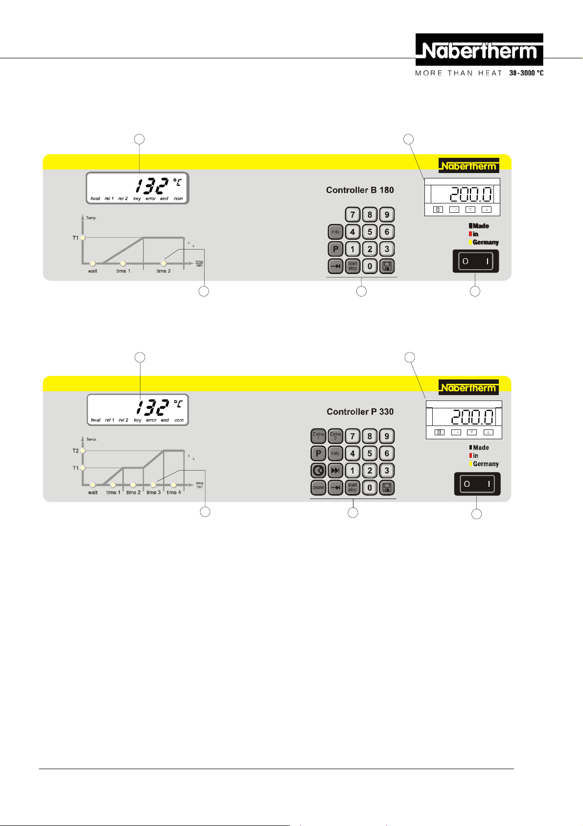
3 Control Fields and Display
Pos: 21 /TD/Betrieb_Bedienung/Controller/B 150/ B130/B170/C280/C290/C295/P320/Bedienfelder/B180 @ 5\mod_12094 57499159_51.doc @ 36117 @
B 180
56
Fig. 1: B 180 control panel
Pos: 22 /TD/Betrieb_Bedienung/Controller/B 150/ B130/B170/C280/C290/C295/P320/Bedienfelder/P330 @ 5\mod_12094 56948677_51.doc @ 36101 @
P 330
5
2132iEurotherm
27x12,7
123
6
3
Fig. 2: P 330 control panel
Pos: 23 /TD/Betrieb_Bedienung/Controller/B 150/ B130/B170/C280/C290/C295/P320/Bedienfelder/Legende B 180 und P 330 @ 7\ mo d_12 33845191857_51.doc @ 49523 @
Pos: 24 /=== Seitenumbruch === @ 0\mod_1158819844943_0.doc @ 2983 @
1 = Power switch
2 = Keyboard block
3 = Program LED
4 = - - -
5 = Display
6 = Over-temperature limit controller (optional)
2132iEurotherm
27x12,7
2
1
Headquarters: 10/56
Nabertherm GmbH . Bahnhofstr. 20 .28865 Lilienthal/Bremen, Germany . Tel +49 (4298) 922-0, Fax -129 . contact@nabertherm.de . www.nabertherm.com
Page 11
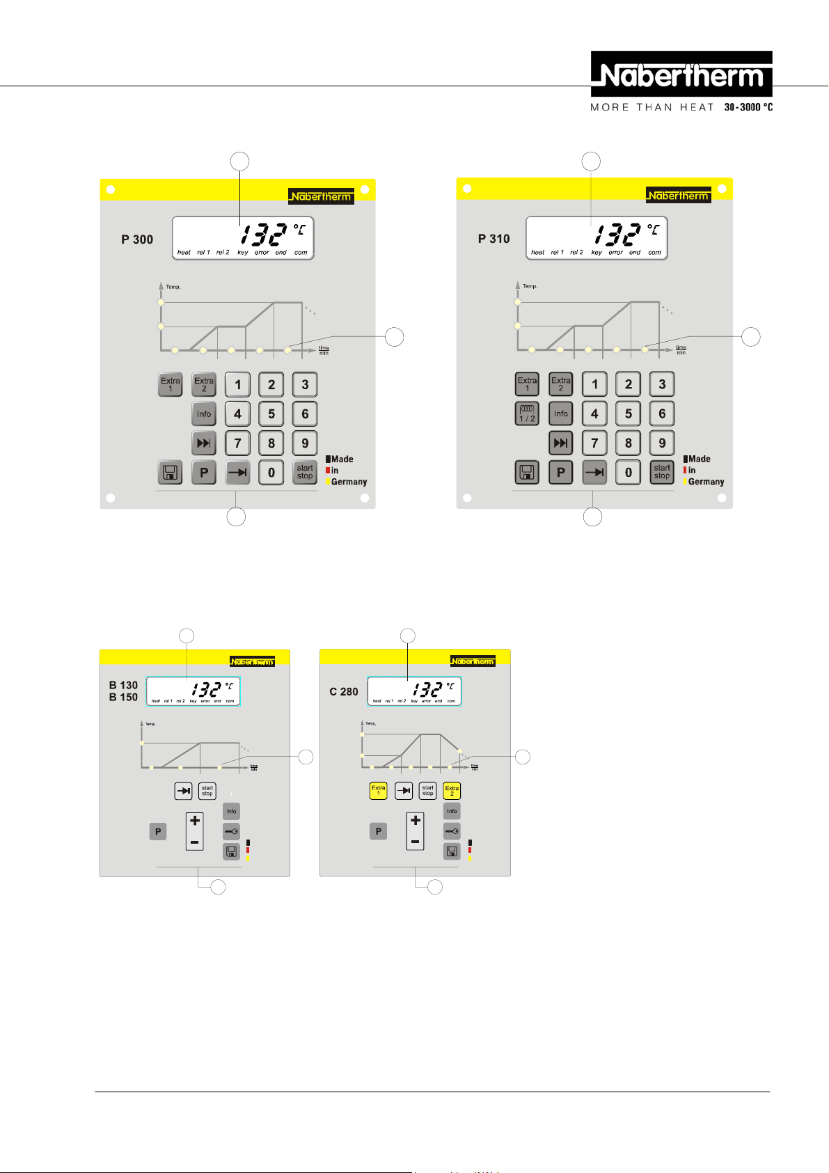
Pos: 25 /TD/Betrieb_Bedienung/Controller/B 150/ B130/B170/C280/C290/C295/P320/Bedienfelder/ P 300 und P 310 @ 7\mod_12338 45695184_51.doc @ 49539 @
P 300/P 310
5 5
T2
T1
wait time 3 time 4time 2time 1
2 2
Fig. 3: P 300/P 310 control panel
Pos: 26 /TD/Betrieb_Bedienung/Controller/B 150/ B130/B170/C280/C290/C295/P320/Bedienfelder/B130/B150C2 80 @ 7\ mod_1233837787769_51.doc @ 49443 @
B 130/B 150/C 280
5 5
T2
T1
3
wait time 3 time 4time 2time 1
3
1 = - - -
2 = Keyboard block
3 = Program LED
T1
wait time 2time 1
Made
in
Germany
3 3
T2
T1
wait time 3 time 4time 2time 1
T3
Made
in
Germany
22
Fig. 4: B 130/B 150/C 280 control panel
Pos: 27 /=== Seitenumbruch === @ 0\mod_1158819844943_0.doc @ 2983 @
Headquarters: 11/56
Nabertherm GmbH . Bahnhofstr. 20 .28865 Lilienthal/Bremen, Germany . Tel +49 (4298) 922-0, Fax -129 . contact@nabertherm.de . www.nabertherm.com
4 = - - -
5 = Display
6 = - - -
Page 12
Pos: 28 /TD/Betrieb_Bedienung/Controller/B 150/ B130/B170/C280/C290/C295/P320/Displays/Überschrift - Displays @ 0\mod_1168867379777_51.doc @ 6302 @ 2
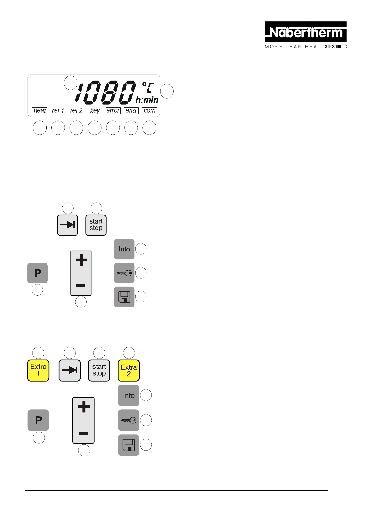
3.1 Displays
Pos: 29 /TD/Betrieb_Bedienung/Controller/B 150/ B130/B170/C280/C290/C295/P320/Displays/B130/B150/B170/ B180/ C280/C290/C295/P300/P310/P330 @ 0\mod_1168868366031_51.doc @ 6320 @
1
1 = Furnace temperature
2 = Temperature unit °C/°F
3 = Heating on
4 = Extra relay 1 ON
5 = Extra relay 2 ON (or ventilation motor ON
32456789
Fig. 5: Display
Pos: 30 /TD/Betrieb_Bedienung/Controller/B 150/ B130/B170/C280/C290/C295/P320/Tastaturblöcke/Übersc hr ift - Tastaturblöcke @ 0\mod_1168858756210_51.doc @ 6221 @ 2
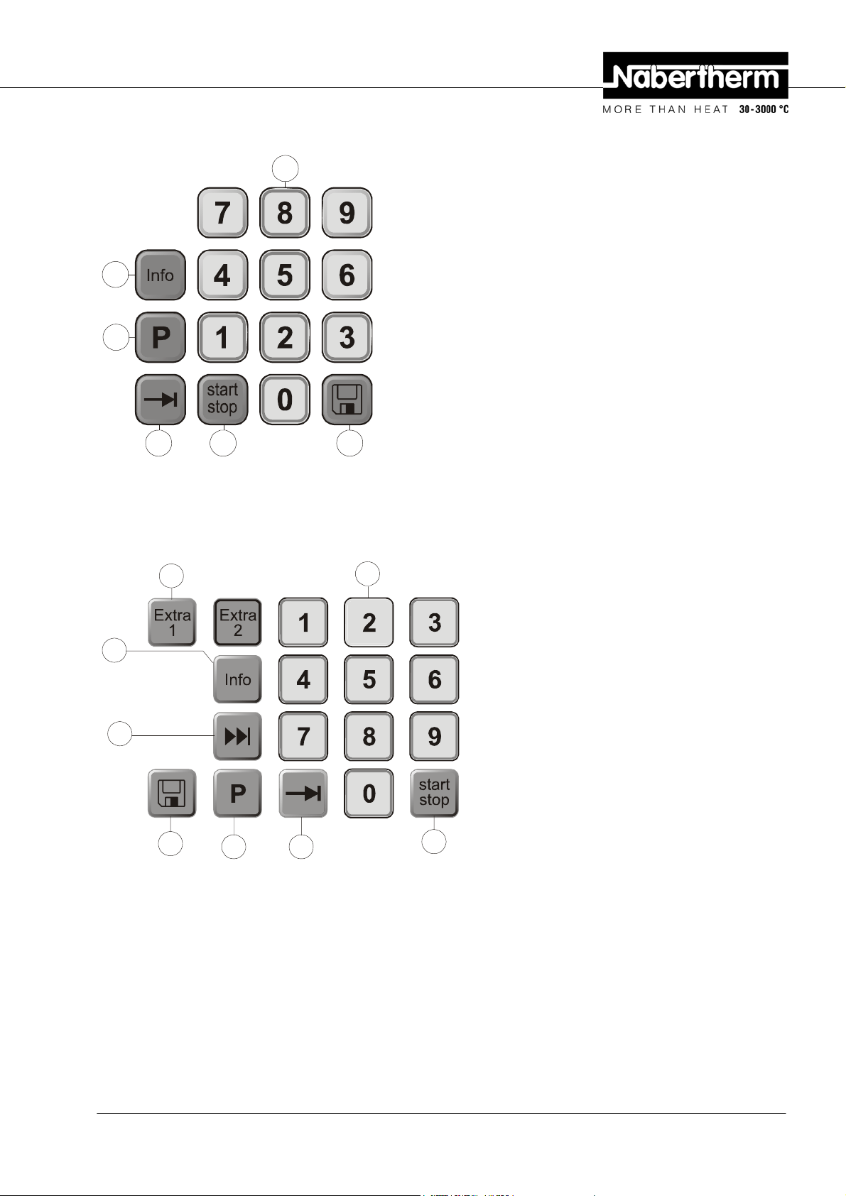
3.2 Keyboard Blocks
Pos: 31 /TD/Betrieb_Bedienung/Controller/B 150/ B130/B170/C280/C290/C295/P320/Tastaturblöcke/B130/B150 und Le gende @ 7\mod_1233838025910_51.doc @ 49459 @
B 130/B 150
4 5
6
7
1
8
2
Fig. 6: B 130/B 150 keyboard block
6 = Key lock (B 130/C 280 only)
7 = Error message
8 = Program end
9 = PC communication (optional)
1 = Program selection
2 = +/-
3 = - - -
4 = Page
5 = Program start/stop
6 = Info menu
7 = Key lock
8 = Save
Pos: 32 /TD/Betrieb_Bedienung/Controller/B 150/ B130/B170/C280/C290/C295/P320/Tastaturblöcke/C280 und Legen de @ 7\ mod_1233843516307_51.doc @ 49483 @
C 280
1 = Program selection
3 4 5 3
2 = +/-
3 = Extra functions
4 = Page
6
5 = Program start/stop
6 = Info menu
7 = Key lock
7
8 = Save
1
8
2
Fig. 7: C 280 keyboard block
Pos: 33 /=== Seitenumbruch === @ 0\mod_1158819844943_0.doc @ 2983 @
Headquarters: 12/56
Nabertherm GmbH . Bahnhofstr. 20 .28865 Lilienthal/Bremen, Germany . Tel +49 (4298) 922-0, Fax -129 . contact@nabertherm.de . www.nabertherm.com
Page 13
Pos: 34 /TD/Betrieb_Bedienung/Controller/B 150/ B130/B170/C280/C290/C295/P320/Tastaturblöcke/B180 und Lege nde @ 7\ mod_1233850588652_51.doc @ 49609 @
B 180
6
1
45 8
Fig. 8: B 180 keyboard block
Pos: 35 /TD/Betrieb_Bedienung/Controller/B 150/ B130/B170/C280/C290/C295/P320/Tastaturblöcke/P300 und Lege nde @ 7\ mod_1233846166420_51.doc @ 49555 @
P 300
3
2
1 = Program selection
2 = Numerical block
3 = - - -
4 = Page
5 = Program start/stop
6 = Info menu
7 = - - -
8 = Save
2
6
7
8
Fig. 9: P 300 keyboard block
Pos: 36 /=== Seitenumbruch === @ 0\mod_1158819844943_0.doc @ 2983 @
1
1 = Program selection
2 = Numerical block
3 = Extra functions
4 = Page
5 = Program start/stop
6 = Info menu
7 = Segment skip
8 = Save
4
5
Headquarters: 13/56
Nabertherm GmbH . Bahnhofstr. 20 .28865 Lilienthal/Bremen, Germany . Tel +49 (4298) 922-0, Fax -129 . contact@nabertherm.de . www.nabertherm.com
Page 14
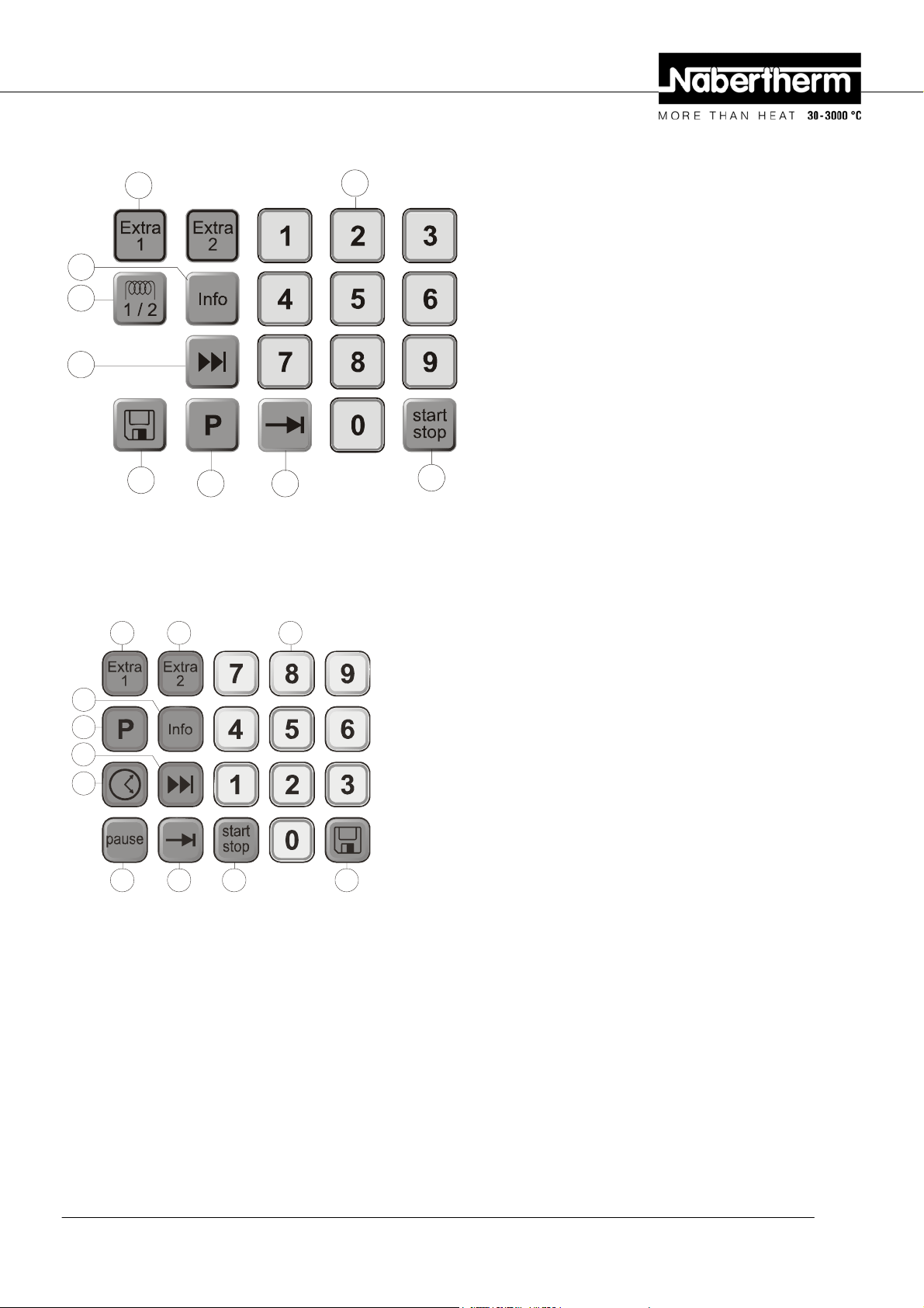
Pos: 37 /TD/Betrieb_Bedienung/Controller/B 150/ B130/B170/C280/C290/C295/P320/Tastaturblöcke/P310 und Lege nde @ 7\ mod_1233846249883_51.doc @ 49571 @
P 310
3
6
9
7
8
Fig. 10: P 310 keyboard block
Pos: 38 /TD/Betrieb_Bedienung/Controller/B 150/ B130/B170/C280/C290/C295/P320/Tastaturblöcke/P330 und Lege nde @ 7\ mod_1233850309077_51.doc @ 49593 @
P 330
3
1
3
2
1 = Program selection
2 = Numerical block
3 = Extra functions
4 = Page
5 = Program start/stop
6 = Info menu
7 = Segment skip
8 = Save
9 = Heating circuit
4
2
5
1 = Program selection
6
1
7
10
9
Fig. 11: P 330 keyboard block
Pos: 39 /=== Seitenumbruch === @ 0\mod_1158819844943_0.doc @ 2983 @
45 8
2 = Numerical block
3 = Extra functions
4 = Page
5 = Program start/stop
6 = Info menu
7 = Segment skip
8 = Save
9 = Pause
10 = Time
Headquarters: 14/56
Nabertherm GmbH . Bahnhofstr. 20 .28865 Lilienthal/Bremen, Germany . Tel +49 (4298) 922-0, Fax -129 . contact@nabertherm.de . www.nabertherm.com
Page 15

Pos: 40 /TD/Betrieb_Bedienung/Controller/B 150/ B130/B170/C280/C290/C295/P320/Überschrift - Eigenschaften der Kon troller @ 0\mod_1168946054727_51.doc @ 6512 @ 1
4 Features of the Controller
Pos: 41 /TD/Betrieb_Bedienung/Controller/B 150/ B130/B170/C280/C290/C295/P320/Eigenschaften der Kontroller ( alle Controller) @ 7\mod_1233915567692_51.doc @ 49663 @ 2
4.1 Functions
Controller
Function
Over-temperature protection 1)
Extra relay function
Manual configuration of the
heating circuits
Air circulation motor control 2)
Waiting time
Number of programs
Number of segments
Auto tune
kW/hr counter 3)
Operating hours counter
Real-time clock
Acoustic signal
RS-422 data interface
Constant heat output
B 130 B 150 B180 C 280 P 300 P 310 P 330
√ √ √ √ √ √ √
- - - 2 2
4)
2
4)
2
4)
- - - - - √ -
√ √ √ √ √ √
√ √ √ √ √ √ √
2 1 1 9 9 9 9
4 2 2 4 40 40 40
√ √ √ √ √ √ √
√ √ √ √ √ √ √
√ √ √ √ √ √ √
- - - - - - √
- - - - - - √
Optional Optional Optional Optional Optional Optional Optional
- - - - - √ Optional
10-key keyboard
Pos: 42 /TD/Betrieb_Bedienung/Controller/B 150/ B130/B170/C280/C290/C295/P320/1) Mit Programmstart wird die höchs te im Programm eingestellte Temperatur ermittelt ... @ 1\mod_1176292760467_51.doc @ 12854 @
- - √ - √ √ √
1) When the program starts, the highest temperature in the program is calculated. If the furnace is 30°C warmer than the
highest program temperature for 3 minutes during the program sequence, the controller turns off the heating and the
safety relay, and a fault message appears.
Pos: 43 /TD/Betrieb_Bedienung/Controller/B 150/ B130/B170/C280/C290/C295/P320/2) Voreingestellte Funktion bei Umluftöfen: Sobald ein Programm am ... @ 1\mod_1176292979087_51.doc @ 12864 @
2) Preconfigured function for circulation furnaces: Once a program has been started on the controller, the air circulation
motor starts. It remains in operation until the program terminates or is interrupted, and the furnace temperature falls
back below 80°C. Extra function 2 is no longer available with this function.
Pos: 44 /TD/Betrieb_Bedienung/Controller/B 150/ B130/B170/C280/C290/C295/P320/3) Der kW/h Zähler berechnet über die Ei nschaltzeit der Heizung, den theoretisch ... @ 1\mod_1176293183301_51.doc @ 12875 @
3) The kW/hr counter calculates the power theoretically consumed over the time the heater is turned on for a heating
program at nominal voltage. However, there may actually be deviations: If the voltage is low, the power consumption
displayed will be too high, and for a higher voltage the power consumption displayed will be too low.
Pos: 45 /TD/Betrieb_Bedienung/Controller/B 150/ B130/B170/C280/C290/C295/P320/4) Bei Öfen mit einem Luftumwälzmotor s teht in der Regel nur eine Extra-Funktion zur Verfügung .. @ 4\mod_120056305943 5_51.doc @ 30603 @
4) In furnaces with an air circulation motor, only one extra function is usually available (see furnace operating
instructions).
Pos: 46 /=== Seitenumbruch === @ 0\mod_1158819844943_0.doc @ 2983 @
Headquarters: 15/56
Nabertherm GmbH . Bahnhofstr. 20 .28865 Lilienthal/Bremen, Germany . Tel +49 (4298) 922-0, Fax -129 . contact@nabertherm.de . www.nabertherm.com
Page 16
Pos: 47 /TD/Betrieb_Bedienung/Controller/B 150/ B130/B170/C280/C290/C295/P320/Überschrift - Neue Funktionen der Nabertherm Controller @ 1\mod_1173192128446_51.doc @ 10423 @ 1
5 New Functions of the Nabertherm Controller
Pos: 48 /TD/Betrieb_Bedienung/Controller/B 150/ B130/B170/C280/C290/C295/P320/Programmeingabe mit/ohne Gradi ent ab Controller Version 3.xx @ 5\mod_1210665723438_51.doc @ 36633 @ 2
5.1 Program Entry with/without Gradient as of Version 3.xx
As of controller version 3.xx you can enter ramps either as gradients (e.g. 120°C/h) or using
the "time and target temperature" combination.
Turn the controller off and on again briefly to be able to read the version number.
The input mode can be changed on a user-specific basis in the configuration in support of
the process specification. To change the input mode, see "Configuration"
The mode configured can be seen during program input in a segment, e.g. "time 1", as
follows:
For "time and set temperature" input, only °C/°F or the time h is displayed as the input
unit. For gradient input, °C/°F and h appear together in the display as the unit. The
maximum gradient is 6000°C (fast heating)
Pos: 49 /TD/Betrieb_Bedienung/Controller/B 150/ B130/B170/C280/C290/C295/P320/Die Zeiteinheit für die Gradient eneingabe ist fest auf Stunde (h) eingestellt ... @ 5\mod_1210666214044_51.doc @ 36655 @
Pos: 50 /TD/Betrieb_Bedienung/Controller/B 150/ B130/B170/C280/C290/C295/P320/Programmstartverhalten bei warmen Ofen ab Controller Version 3.xx @ 1\mod_1173192896751_51.doc @ 10442 @ 2
Note
The unit of time for the gradient input is preset to hours (h) and cannot be changed to
minutes.
Example: 100°C/h
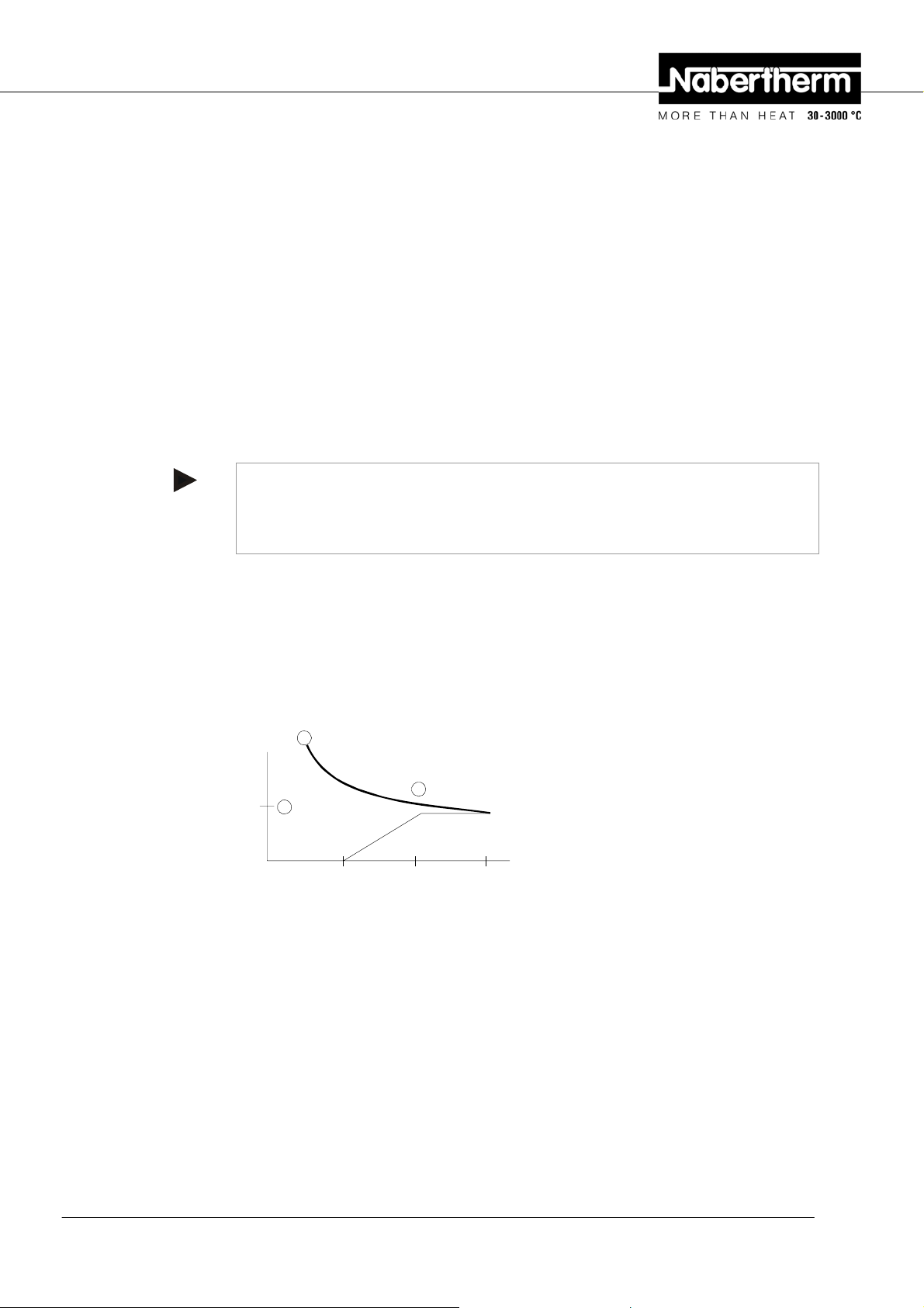
5.2 Program Starting Behavior for warm Furnaces as of Controller Version 3.xx
If the furnace temperature c at program start is higher than the set temperature d of the
first segment "T 1", the program start is delayed until the furnace chamber temperature
cools to a value of T1 + 10 °C e. That is, segment "Time 1" is skipped and the program
start occurs in the following segment "Time 2".
1
3
T 1
2
Time 1 Time 2
Fig. 12: Program start behavior
This program start behavior is permanently programmed into all controllers as of version
number 3.xx and cannot be changed. Turn the controller off and on again briefly to be able
to read the version number.
Pos: 51 /TD/Betrieb_Bedienung/Controller/B 150/ B130/B170/C280/C290/C295/P320/Spanungsausfallverhalten @ 1\ mod_1173193408926_51.doc @ 10451 @ 2
5.3 Power Failure Behavior
As of controller version 3.xx the power failure behavior can be configured.
Turn the controller off and on again briefly to be able to read the version number. To
change the power failure behavior, see chapter "Configuration/customer-specific
settings".
Pos: 52 /TD/Betrieb_Bedienung/Controller/B 150/ B130/B170/C280/C290/C295/P320/Überschrift - Controller B130/C2 80 @ 7\mod_1233921605957_51.doc @ 49679 @ 1
Headquarters: 16/56
Nabertherm GmbH . Bahnhofstr. 20 .28865 Lilienthal/Bremen, Germany . Tel +49 (4298) 922-0, Fax -129 . contact@nabertherm.de . www.nabertherm.com
Page 17
6 Controller B 130/C 280
Pos: 53 /TD/Betrieb_Bedienung/Controller/B 150/ B130/B170/C280/C290/C295/P320/Kurzanleitung/Überschri ft - Kurzanleitung @ 0\mod_1169544239740_51.doc @ 7618 @ 2
6.1 Brief Instructions
Pos: 54 /TD/Betrieb_Bedienung/Controller/B 150/ B130/B170/C280/C290/C295/P320/Kurzanleitung/Controller ei nschalten B130/C280 @ 7\mod_1233925936587_51.doc @ 49705 @
Turning on the
controller
27x12,7
Display Version number Temperature display
Example: controller type
Pos: 55 /TD/Betrieb_Bedienung/Controller/B 150/ B130/B170/C280/C290/C295/P320/Kurzanleitung/Program m aufr ufen B130/B150/C280/C290/C295 @ 1\mod_1173193921396_51.doc @ 10460 @
Call program
Confirm program selection with
Pos: 56 /TD/Betrieb_Bedienung/Controller/B 150/ B130/B170/C280/C290/C295/P320/Kurzanleitung/Program m eingeb en/kontrollieren B130/B150/C280 @ 7\mod_1234361168010_51.doc @ 50225 @
Enter / control
program
Pos: 57 /TD/Betrieb_Bedienung/Controller/B 150/ B130/B170/C280/C290/C295/P320/Kurzanleitung/Program m star ten B130/B150/B170/B180/C280/C290/C295/P230/P330 @ 1\mod_117319 4624787_51.doc @ 10478 @
Start program
Display
. . .
time 1
Enter time
segment 1
T 1
Enter
temperature 1
time 2
Enter time
segment 2
Display
Pos: 58 /=== Seitenumbruch === @ 0\mod_1158819844943_0.doc @ 2983 @
Headquarters: 17/56
Nabertherm GmbH . Bahnhofstr. 20 .28865 Lilienthal/Bremen, Germany . Tel +49 (4298) 922-0, Fax -129 . contact@nabertherm.de . www.nabertherm.com
Page 18
Pos: 59 /TD/Betrieb_Bedienung/Controller/B 150/ B130/B170/C280/C290/C295/P320/Überschrift - Programme/W artezeit einstellen oder verändern @ 1\mod_1174634424831_51.doc @ 12333 @ 2
6.2 Setting or changing Program/Waiting Time
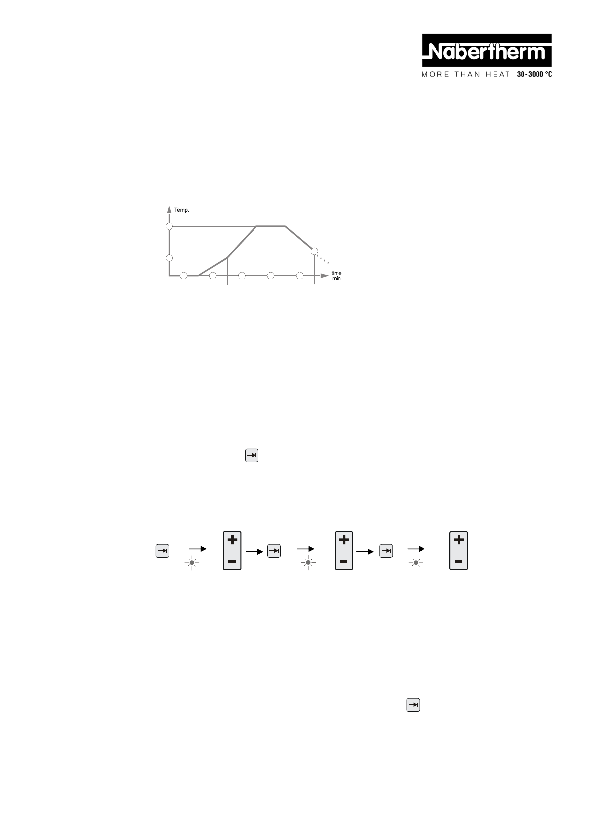
Pos: 60 /TD/Betrieb_Bedienung/Controller/B 150/ B130/B170/C280/C290/C295/P320/Programme/Wartezeit einste l len oder verändern B130/C280 - 1 @ 0\mod_1169026202596_51.doc @ 6930 @
For the automatic operation of the furnace, before starting the controller a temperature
characteristic must be configured which describes the desired temperature behavior. This
configured temperature behavior is also called a heating program.
Each heating program for the B 130 and C 280 has two ramps, one holding time, and one
cooling ramp.
T2
T1
wait time 3 time 4time 2time 1
T3
Fig. 13: Program graphic, B 130/C 280
− In the ramps, a segment temperature "T" and a segment time, "time 1" and "time
2" define a linear temperature increase (slow heating).
− In the holding time, "time 3"determines how long the temperature value
configured in "T 2" should be held.
− In the cooling time, the natural cooling can be slowed using the rate set in "T 3"
and "time 4". If there is no specification in "T 3" and "time 4", the
program is already terminated after "time 3" has elapsed.
Program Entry
Using the paging key
you can enter input mode. Every push selects the following
segment or time value. The selected value is displayed with the blinking LED for either "T"
or "time".
Pos: 61 /TD/Betrieb_Bedienung/Controller/B 150/ B130/B170/C280/C290/C295/P320/Kurzanleitung/Program m eingeb en/kontrollieren B130/B150/C280 @ 7\mod_1234361168010_51.doc @ 50225 @
Enter / control
program
. . .
time 1
Enter time
segment 1
T 1
Enter
temperature 1
time 2
Enter time
segment 2
Pos: 62 /TD/Betrieb_Bedienung/Controller/B 150/ B130/B170/C280/C290/C295/P320/Programme/Wartezeit einste l len oder verändern B130/C280/ - 2 @ 1\mod_1174639619097_51.doc @ 12354 @
In the display, the temperature value "T" or time value "time" corresponding to the flashing
LED is shown.
Pos: 63 /TD/Betrieb_Bedienung/Controller/B 150/ B130/B170/C280/C290/C295/P320/Programme/Wartezeit einste l len oder verändern B130/B150/C280 @ 7\mod_1234362060765_51.doc @ 50257 @
If the value displayed should not be changed, use the page key to page to the next
temperature or time value.
The display also shows the unit of the value expected:
Headquarters: 18/56
Nabertherm GmbH . Bahnhofstr. 20 .28865 Lilienthal/Bremen, Germany . Tel +49 (4298) 922-0, Fax -129 . contact@nabertherm.de . www.nabertherm.com
Page 19

- set temperature values with °C/°F
- set time specifications with hr:min
- set gradient specifications with °C/hr:min or °F/hr:min
If a value should be changed, you can set it with the
Each time you press the
If you hold the
key down, the value first changes in steps of 10,
and if you hold the
key, the value changes by 1 °C or by one minute.
key down for a longer time, the value changes in steps of 100.
key.
Times are entered in hours and minutes, e.g. 6 hr and 30 min as 06:30.
For holding times, an entry of 99:59 means program execution will continue forever.
When input is complete, the program can be started (see Starting the program).
If ramps contain the time entry 00:00, the controller attempts to reach the temperature value
stored in "T" as quickly as possible
If no key is pressed for 60 seconds, the display automatically returns to the display of
temperature. Changed settings are initially only buffered. If a changed or new program
should be permanently stored in the controller for more frequent use, see "Saving
Programs".
Note
Not all segments have to be programmed. For segments which are not needed, the
temperature and time values must be set to "0". The controller then automatically ends the
program after the last segment programmed
Pos: 64 /TD/Betrieb_Bedienung/Controller/B 150/ B130/B170/C280/C290/C295/P320/Wartezeit einstellen oder veränd ern B150/B180/P300/P310 @ 7\mod_1233926255573_51.doc @ 49731 @ 2
6.3 Setting or Changing the Waiting Time
B 150/B 180/P 300/P 310 waiting time
To start a heating program automatically at a later point in time, e.g. after a drying time, a
waiting time ("wait") can be programmed.
To select the waiting time, press the
Times are entered in hours and minutes, e.g. 6 hrs and 30 min as 06:30, i.e., when a heating
program is started, first the wait time elapses and only then does the program start with
segment 1 and heating.
Pos: 65 /=== Seitenumbruch === @ 0\mod_1158819844943_0.doc @ 2983 @
key repeatedly until the
wait
LED flashes.
Headquarters: 19/56
Nabertherm GmbH . Bahnhofstr. 20 .28865 Lilienthal/Bremen, Germany . Tel +49 (4298) 922-0, Fax -129 . contact@nabertherm.de . www.nabertherm.com
Page 20

Pos: 66 /TD/Betrieb_Bedienung/Controller/B 150/ B130/B170/C280/C290/C295/P320/Programmierung der Extrafunk ti onen B 130/B150/C280/C290/C295 @ 1\mod_1173260029266_51.doc @ 10552 @ 2
6.4 Programming Extra Functions
With controllers of types "C" and "P", up to two optional extra functions "Extra 1" and
"Extra 2" can be turned on or off in the segments depending on the program
Extra functions are, for instance, exhaust air flaps, fans, solenoids, or optical and acoustic
signals, which have been included in the furnace (if applicable, see additional operating
instructions for extra functions)
These extra functions can be specified during program entry in all segments, e.g. "time 1",
by selecting the "Extra 1" or "Extra 2" key.
That is, when the controller processes the programmed segment, the extra functions are
automatically turned on and then turned back of in the next segment, for instance.
Programming of extra functions is done during program entry.
The desired segment must be selected as described in "Entering programs/wait time", so
that the corresponding LED, e.g. "time 1", is flashing.
If the "Extra 1" or "Extra 2" key is now pressed, the extra function is specified for this
segment, and in the display the status field "REL 1" lights up for "Extra 1" and/or "REL
2" for "Extra 2". During program execution, the programmed extra function is
automatically turned on during this segment.
To turn off the specification of an extra function, press the corresponding "Extra" key
again – in the display, the status field "REL 1" or "REL 2" disappears – the extra function
is now no longer turned on. Both extra functions can also be activated at the same time.
time 1 T1
Fig. 14: Selection of "Extra 1 funktion" in segment "time 1"; LED "time 1" flashes
wait time 1
Fig. 15: In the display, "REL 1" lights up for the selected "Extra 1 funktion"
When paging through the program with
, programmed extra functions are indicated in
each segment ("time" LED flashing) with the status fields "REL 1" or "REL 2" in the
display – if the status fields do not light up, the extra functions are not specified.
Note
The programming of extra functions is saved along with storage of heating programs!
Pos: 67 /TD/Betrieb_Bedienung/Controller/B 150/ B130/B170/C280/C290/C295/P320/Programmierung der Extrafunk ti onen i n „T3“ (nur C 280) @ 1\mod_1174385526182_51.doc @ 11383 @ 2
Headquarters: 20/56
Nabertherm GmbH . Bahnhofstr. 20 .28865 Lilienthal/Bremen, Germany . Tel +49 (4298) 922-0, Fax -129 . contact@nabertherm.de . www.nabertherm.com
Page 21
6.5 Programming Extra Functions in "T3" (C 280 only)
When programming extra functions in the program value "T3" (C 280 only), the extra
function stays turned on after conclusion of the program, for instance in order to continue
cooling the furnace with a cooling fan.
Extra functions which are automatically turned on during program execution by "T3" must
be turned off by hand if necessary.
Pos: 68 /TD/Betrieb_Bedienung/Controller/B 150/ B130/B170/C280/C290/C295/P320/Extrafunktionen im Programmab lauf manuell Ein- und Ausschalten B 130/150/C 280/C290/295 @ 1\mod_117438586561 7_51.doc @ 11393 @ 2
6.6 Turning Extra Functions in Program Execution on and off by Hand
Extra functions can be turned on or off during a started program, for the active segment or
after termination of the program, by pressing the corresponding "Extra" key.
If an extra function is turned on during a running program, it remains on until the programspecific segment transition to the following segment occurs.
Pos: 69 /TD/Betrieb_Bedienung/Controller/B 150/ B130/B170/C280/C290/C295/P320/Programme speichern B130/B150/C 280 @ 7\ mod_1234362375876_51.doc @ 50273 @ 2
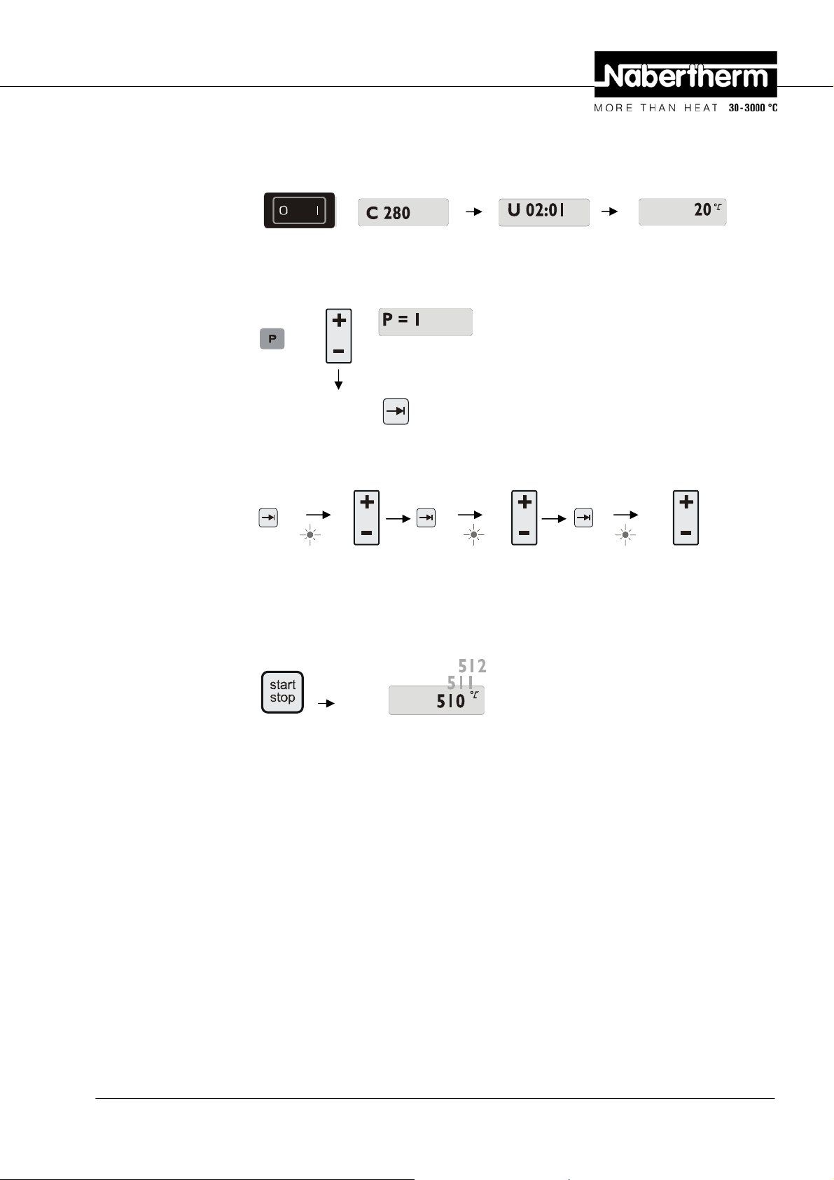
6.7 Saving Programs
Changed settings are initially only buffered. That is, buffered programs are overwritten
once a different program is started. If a changed or new program should be permanently
saved in the controller for more frequent use, it can be saved to a permanent program slot as
follows:
Press the save key
The number can be changed to the desired program number using
Pressing the save key
– a program number appears in the display.
again finally saves to the selected program slot.
+
-
.
Pos: 70 /TD/Betrieb_Bedienung/Controller/B 150/ B130/B170/C280/C290/C295/P320/Programme speichern B130/B150/C 280/ C290/C295/P320 - 2 @ 1\mod_1174405559639_51.doc @ 12203 @
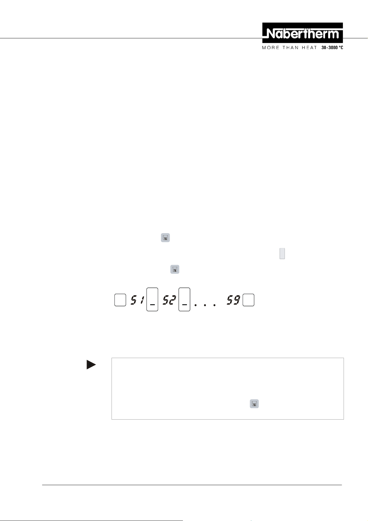
Pos: 71 /TD/Betrieb_Bedienung/Controller/B 150/ B130/B170/C280/C290/C295/P320/Voreingestellte Programme B 130/C 280 @ 1\ mod_1174386532079_51.doc @ 11413 @ 2
++
Fig. 16: Saving a program to program slot no. 9
The program can now be called up from this storage slot at any time (see Program start)
Note
Existing heating programs already saved in a storage slot will be overwritten with no
message or warning. Saved heating programs are still retained after the controller is turned
off. Configured waiting times are not saved. They must be reentered before each process!
The controller automatically returns to the display of the furnace temperature after about 10
seconds when you save without pressing the save key
buffered in this case.
again. The program is only
Headquarters: 21/56
Nabertherm GmbH . Bahnhofstr. 20 .28865 Lilienthal/Bremen, Germany . Tel +49 (4298) 922-0, Fax -129 . contact@nabertherm.de . www.nabertherm.com
Page 22

6.8 Preconfigured Programs for the B 130/C 280
The following programs are preconfigured and can be started directly.
"Baking" refers to the baking of clay, while "glazing" refers to the baking of glazes.
Note
In any case, note the specifications and instructions of the raw material manufacturers,
which may make it necessary to change or adapt the preconfigured programs. It cannot be
guaranteed that optimum results can be obtained with the preconfigured programs. The
configured factory programs can be overwritten for your own purposes (see Setting
programs/wait time).
B 130
Î
T1 Time1 T2 Time2 Time3 Time4 T3
P1 650 6:00 900 0:00 0:20 0:00 0 Baking
P2 500 3:00 1050 0:00 0:20 0:00 0 Glazing
C 280
Î
T1 Time1 T2 Time2 Time3 Time4 T3
P1 650 3:00 900 0:00 0:20 0:00 0 Baking 1
P2 650 6:00 900 0:00 0:20 0:00 0 Baking 2
P3 650 5:00 1100 0:00 0:30 0:00 0 Baking 3
P4 320 2:00 1050 0:00 0:20 0:00 0 Glazing 1
P5 500 3:00 1050 0:00 0:20 0:00 0 Glazing 2
P6 500 3:00 1200 0:00 0:20 0:00 0 Glazing 3
P7 Unused
P8 Unused
P9 Unused
Note
For furnace models with lower maximum temperatures, the programs listed above are
adapted at the factory to the maximum temperature of the furnace.
Pos: 72 /TD/Betrieb_Bedienung/Controller/B 150/ B130/B170/C280/C290/C295/P320/Überschrift - Programme aufruf en @ 1\mod_1174648969015_51.doc @ 12376 @ 2
6.9 Calling Programs
Pos: 73 /TD/Betrieb_Bedienung/Controller/B 150/ B130/B170/C280/C290/C295/P320/Programme aufrufen B130/B150/C 280 @ 7\ mod_1234362533901_51.doc @ 50289 @
Start saved programs with the P key. Use the
number and monitor the program using the
++
Fig. 17: Starting heating program no. 9
Pos: 74 /TD/Betrieb_Bedienung/Controller/B 150/ B130/B170/C280/C290/C295/P320/Programme aufrufen (Hinweis) B130/ B150/B170/C280/C290/C295/P320 - 2 @ 1\mod_1174407235343_51.doc @ 12236 @
Headquarters: 22/56
Nabertherm GmbH . Bahnhofstr. 20 .28865 Lilienthal/Bremen, Germany . Tel +49 (4298) 922-0, Fax -129 . contact@nabertherm.de . www.nabertherm.com
+
-
key to select the desired program
key.
Page 23

Note
Check the heating program called up before starting it, to be sure that it is the right heating
program.
As of version 3, heating programs are reloaded after program termination.That is, the
heating program can be started after a process without having to reenter it. Turn the
controller off and on again briefly to be able to read the version number .
Pos: 75 /TD/Betrieb_Bedienung/Controller/B 150/ B130/B170/C280/C290/C295/P320/Programmstart B130/B150/C280/ C290/C295 @ 0\mod_1169026395783_51.doc @ 6939 @ 2
6.10 Program Start
After a heating program is entered or called up, it can be started with the
As of version 3: if the furnace temperature at the starting time is higher than the
temperature specified in "T 1", the controller first waits until the temperature of the warm
furnace has fallen to the first segment temperature T1, and only then does it start the rest of
the program's execution. (See also Chapter "New functions of the Nabertherm controller").
For a cold furnace, the heating program is started immediately.
If the heating program has been started, during program execution the LED of the active
segment "time 1 – time 4" lights up. The controller regulates the configured temperature
profile completely automatically and the status field "heat" lights up in the heating cycle.
If the waiting time is set, the LED "wait" first lights up and the display counts down the
remaining waiting time. The status field "heat" only lights up after program start in
segment "time 1" if the heater is turned on. After conclusion of the last segment, the heater
is turned off and the program terminates. In the display, the end of the program is indicated
with the message "end".
Pos: 76 /TD/Betrieb_Bedienung/Controller/B 150/ B130/B170/C280/C290/C295/P320/Programmänderung im Programmabl auf B130/B150/C 280 @ 7\mod_1234362637073_51.doc @ 50305 @ 2
6.11 Program Change During Execution
During program execution, program changes can be made as follows:
Use the paging key
or time value. The selected value is displayed with the flashing LED for either "T" or
"time".
In the display, the temperature value "T" or time value "time" corresponding to the flashing
LED is shown. Holding times can be changed in steps of 5 minutes and temperatures by +/1 °C/°F. If the value displayed should not be changed, use the page key
next segment or time value. All temperature and time values, as well as the extra functions,
can be changed; the only exception is the segment time of the ramp currently being
processed.
Note
to enter input mode. Each key press selects the following segment
start
stop
key.
to page to the
Changes to individual values during program execution must be confirmed with
Otherwise, the change will not be accepted. If you only want to change the active
time segment, this can be done without selecting using the paging key
+
-
can use the
key directly to increase or decrease the holding time in steps of five
. To do this, you
.
holding
minutes.
Extra functions can be turned on or off during a started program, for the active segment or
after termination of the program, by pressing the corresponding "Extra" key.
Pos: 77 /TD/Betrieb_Bedienung/Controller/B 150/ B130/B170/C280/C290/C295/P320/Programmabbruch B130/B150/C 280/C 2 90/C295 @ 1\mod_1174388539571_51.doc @ 11443 @ 2
Headquarters: 23/56
Nabertherm GmbH . Bahnhofstr. 20 .28865 Lilienthal/Bremen, Germany . Tel +49 (4298) 922-0, Fax -129 . contact@nabertherm.de . www.nabertherm.com
Page 24

6.12 Terminating a Program
To terminate a program, press the
field "end" lights up. Program termination can be performed at any time.
Note
It is not possible to interrupt a program temporarily!
start
stop
key again. The heater is turned off and the status
Pos: 78 /TD/Betrieb_Bedienung/Controller/B 150/ B130/B170/C280/C290/C295/P320/Tastenverriegelung B130/B150/ C280 @ 0\mod_1169039668540_51.doc @ 7092 @ 2
6.13 Key Locking
Pos: 79 /TD/Betrieb_Bedienung/Controller/B 150/ B130/B170/C280/C290/C295/P320/Infomenü B130/B150/C280/C290/ C295 - 1 @ 0\mod_1169470892509_51.doc @ 7465 @ 2
6.14 Info Menu
Pos: 80 /TD/Betrieb_Bedienung/Controller/B 150/ B130/B170/C280/C290/C295/P320/Infomenü B130/B150/C280/C290/ C295/P320 - 2 @ 1\mod_1174894342983_51.doc @ 12426 @
For protection against unintended or unallowed changes to the program execution, the
keyboard can be locked after program start using the "key lock". Key locking can only be
released by turning the controller off and on again. If the furnace is turned off while a
program is running, see the power failure behavior.
From the info menu, the current program status, program-relevant information, and fault
messages can be read out.
You can reach the info menu by pressing the "Info" key.
Use the "Info" key to page through the entire info menu until the furnace temperature is
displayed again.
Pr Selected program
SP Set temperature value
Pt Program run time of the active/last program, in minutes
E Power consumption of the active/last program, in kW/hr
tt Total operating hours
OP Heating output power in %
F1 Fault buffer of last fault
F2 Fault buffer of next to last fault
Ht Highest program temperature of the active/last program
tA Maximum furnace temperature
Note
The info menu is not automatically switched back to the temperature display, so that you
can observe it for longer periods of time.
Use the "Info" key to page through the entire info menu until the furnace temperature is
displayed again.
Some values are reset after a heating program is started.
Pos: 81 /=== Seitenumbruch === @ 0\mod_1158819844943_0.doc @ 2983 @
Headquarters: 24/56
Nabertherm GmbH . Bahnhofstr. 20 .28865 Lilienthal/Bremen, Germany . Tel +49 (4298) 922-0, Fax -129 . contact@nabertherm.de . www.nabertherm.com
The operating hour counter cannot be reset
Page 25

Pos: 82 /TD/Betrieb_Bedienung/Controller/B 150/ B130/B170/C280/C290/C295/P320/Überschrift - Controller B150 @ 7\m od_1 234162838898_51.doc @ 49753 @ 1
7 Controller B 150
Pos: 83 /TD/Betrieb_Bedienung/Controller/B 150/ B130/B170/C280/C290/C295/P320/Kurzanleitung/Überschri ft - Kurzanleitung @ 0\mod_1169544239740_51.doc @ 7618 @ 2
7.1 Brief Instructions
Pos: 84 /TD/Betrieb_Bedienung/Controller/B 150/ B130/B170/C280/C290/C295/P320/Kurzanleitung/Controller ei nschalten B150/C290/C295 @ 0\mod_1169566365267_51.doc @ 7643 @
Turning on the
controller
27x12,7
Display Version number Temperature display
Example: controller type
Pos: 85 /TD/Betrieb_Bedienung/Controller/B 150/ B130/B170/C280/C290/C295/P320/Kurzanleitung/Program m aufr ufen B130/B150/C280/C290/C295 @ 1\mod_1173193921396_51.doc @ 10460 @
Call program
Confirm program selection with
Pos: 86 /TD/Betrieb_Bedienung/Controller/B 150/ B130/B170/C280/C290/C295/P320/Kurzanleitung/Program m eingeb en/kontrollieren B130/B150/C280 @ 7\mod_1234361168010_51.doc @ 50225 @
Enter / control
program
Pos: 87 /TD/Betrieb_Bedienung/Controller/B 150/ B130/B170/C280/C290/C295/P320/Kurzanleitung/Program m star ten B130/B150/B170/B180/C280/C290/C295/P230/P330 @ 1\mod_117319 4624787_51.doc @ 10478 @
Start program
Display
. . .
time 1
Enter time
segment 1
T 1
Enter
temperature 1
time 2
Enter time
segment 2
Display
Pos: 88 /=== Seitenumbruch === @ 0\mod_1158819844943_0.doc @ 2983 @
Headquarters: 25/56
Nabertherm GmbH . Bahnhofstr. 20 .28865 Lilienthal/Bremen, Germany . Tel +49 (4298) 922-0, Fax -129 . contact@nabertherm.de . www.nabertherm.com
Page 26

Pos: 89 /TD/Betrieb_Bedienung/Controller/B 150/ B130/B170/C280/C290/C295/P320/Überschrift - Controller B180/P3 00/P310/P330 @ 7\mod_1234162979838_51.doc @ 49769 @ 1
8 Controller B 180/P 300/P 310/P 330
Pos: 90 /TD/Betrieb_Bedienung/Controller/B 150/ B130/B170/C280/C290/C295/P320/Kurzanleitung/Überschri ft - Kurzanleitung @ 0\mod_1169544239740_51.doc @ 7618 @ 2
8.1 Brief Instructions
Pos: 91 /TD/Betrieb_Bedienung/Controller/B 150/ B130/B170/C280/C290/C295/P320/Kurzanleitung/Controller ei nschalten B180/P300/P310/P330 @ 5\mod_1209461914143_51.doc @ 36213 @
Turning on the
controller
27x12,7
Display Version number Temperature display
Pos: 92 /TD/Betrieb_Bedienung/Controller/B 150/ B130/B170/C280/C290/C295/P320/Kurzanleitung/Program m eingeb en-Startzeit eingeben-start- B180/P330 @ 5\mod_1209462365500_5 1.doc @ 36229 @
Enter waiting time
wait
Enter waiting time
Display
Enter program
Enter time
segment 1
Confirm input with
Confirm input with
Enter
temperature 1
.
Enter time
segment 2
.
Pos: 93 /TD/Betrieb_Bedienung/Controller/B 150/ B130/B170/C280/C290/C295/P320/Kurzanleitung/Program m star ten B130/B150/B170/B180/C280/C290/C295/P230/P330 @ 1\mod_117319 4624787_51.doc @ 10478 @
Start program
Display
Pos: 94 /=== Seitenumbruch === @ 0\mod_1158819844943_0.doc @ 2983 @
Headquarters: 26/56
Nabertherm GmbH . Bahnhofstr. 20 .28865 Lilienthal/Bremen, Germany . Tel +49 (4298) 922-0, Fax -129 . contact@nabertherm.de . www.nabertherm.com
Page 27

Pos: 95 /TD/Betrieb_Bedienung/Controller/B 150/ B130/B170/C280/C290/C295/P320/Tag/Uhrzeit einstellen und anz ei gen P330 @ 5\mod_1209471331954_51.doc @ 36293 @ 2
8.2 Setting and Displaying the Date/Time on the P 330
The P 330 has a real time clock that is set at the factory. The time of day can be displayed
by pressing the
follows: The clock is set using a numerical combination of the day of the week and the
time. The setting of the day of the week corresponds to the first digit of the numerical
combination. Each day of the week has its own number.
1=Mon, 2=Tue, 3=Wed, 4=Thu, 5=Fri, 6=Sat, 7=Sun.
Entry of the time of day must then be carried out with the last four digits of the combination
using a 24-hour clock:
E.g. 0735 for 7:35 AM, 1700 for 5:00 PM, etc.
key. If the time of day is displayed incorrectly, the clock can be set as
Example: Setting the time "Wednesday (day 3), 7:35 AM"
Fig. 18: Example of setting the clock
The day and time are saved by pressing the
the symbol key
.
This clock is a real-time clock, that is, even when the controller is turned off, the time is
retained using a built-in battery. The lifetime of the battery is about 3 years. When the
battery is replaced, the saved data (set time) is lost. For the battery type, see the chapter
"Technical data".
The time can only be entered and displayed in 24-hour mode, that is, a display of 12:00
AM/PM is not possible. After the time is set, the controller is fully ready for operation.
Pos: 96 /TD/Betrieb_Bedienung/Controller/B 150/ B130/B170/C280/C290/C295/P320/Programme einstellen oder veränder n B150/P300/P310 - 1 @ 7\mod_1234163504356_51.doc @ 49785 @ 2
8.3 Setting or Changing Programs
For the automatic operation of the furnace, before starting the controller a temperature
characteristic must be configured which describes the desired temperature behavior. This
configured temperature behavior is also called a heating program.
key. They can be queried at any time with
P 300/P 310
Each of the 9 heating programs for the P 300/P 310 has 20 ramps and 20 hold times (40
segments in all) which are connected together with the segment blocks A – I.
Headquarters: 27/56
Nabertherm GmbH . Bahnhofstr. 20 .28865 Lilienthal/Bremen, Germany . Tel +49 (4298) 922-0, Fax -129 . contact@nabertherm.de . www.nabertherm.com
Page 28
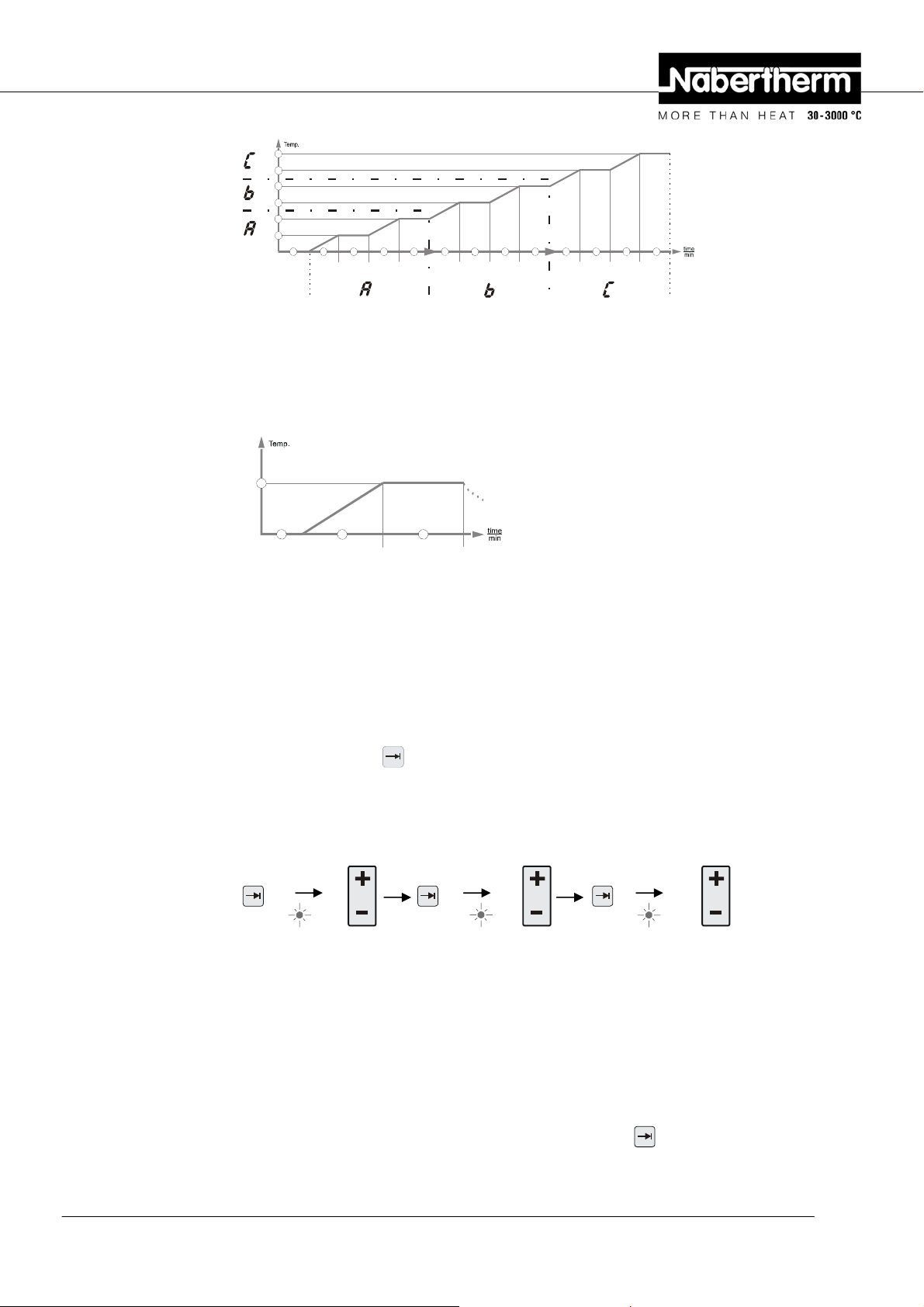
T2
T1
T2
T1
T2
T1
wait time 3 time 3 time 3time 4 time 4 time 4time 2 time 2 time 2time 1 time 1 time 1
Fig. 19: P 300/P 310 program graph
B 150
The heating program for the B 150 has one ramp and one holding time.
Pos: 97 /TD/Betrieb_Bedienung/Controller/B 150/ B130/B170/C280/C290/C295/P320/Kurzanleitung/Program m eingeb en/kontrollieren B130/B150/C280 @ 7\mod_1234361168010_51.doc @ 50225 @
T1
wait time 2time 1
Fig. 20: Program graph, B 150
− In a ramp, a segment temperature "T" and a segment time, e.g. "time 1", define a
linear temperature increase (slow heating).
− In a holding time, e.g. "time 2", it is configured how long the temperature value
configured in "T 1" should be held.
Program input
Using the paging key
you can enter input mode. Each key press selects the following
segment or time value. The selected value is displayed with the flashing LED for either "T"
or "time".
Enter / control
program
. . .
time 1
Enter time
segment 1
T 1
Enter
temperature 1
time 2
Enter time
segment 2
Pos: 98 /TD/Betrieb_Bedienung/Controller/B 150/ B130/B170/C280/C290/C295/P320/Programme/Wartezeit einste l len oder verändern B130/B150/C280/C290/C295 - 2 @ 1\mod_1174639305804_51. doc @ 12343 @
In the display, the corresponding segment block A-I and the temperature value "T" or time
value "time" corresponding to the flashing LED are also shown.
Pos: 99 /TD/Betrieb_Bedienung/Controller/B 150/ B130/B170/C280/C290/C295/P320/Programme/Wartezeit einste l len oder verändern B130/B150/C280 @ 7\mod_1234362060765_51.doc @ 50257 @
If the value displayed should not be changed, use the page key to page to the next
temperature or time value.
Headquarters: 28/56
Nabertherm GmbH . Bahnhofstr. 20 .28865 Lilienthal/Bremen, Germany . Tel +49 (4298) 922-0, Fax -129 . contact@nabertherm.de . www.nabertherm.com
Page 29

The display also shows the unit of the value expected:
- set temperature values with °C/°F
- set time specifications with hr:min
- set gradient specifications with °C/hr:min or °F/hr:min
If a value should be changed, you can set it with the
Each time you press the
If you hold the
key down, the value first changes in steps of 10,
and if you hold the
key, the value changes by 1 °C or by one minute.
key down for a longer time, the value changes in steps of 100.
key.
Times are entered in hours and minutes, e.g. 6 hr and 30 min as 06:30.
For holding times, an entry of 99:59 means program execution will continue forever.
When input is complete, the program can be started (see Starting the program).
If ramps contain the time entry 00:00, the controller attempts to reach the temperature value
stored in "T" as quickly as possible
If no key is pressed for 60 seconds, the display automatically returns to the display of
temperature. Changed settings are initially only buffered. If a changed or new program
should be permanently stored in the controller for more frequent use, see "Saving
Programs".
Note
Not all segments have to be programmed. For segments which are not needed, the
temperature and time values must be set to "0". The controller then automatically ends the
program after the last segment programmed
Pos: 100 /TD/Betrieb_Bedienung/Controller/B 150/ B130/B170/C280/C290/C295/P320/Kurzanleitung/Program m einge ben/kontrollieren P300/P310 @ 7\mod_1234164091088_51.doc @ 49801 @
Enter / control
program
Pos: 101 /TD/Betrieb_Bedienung/Controller/B 150/ B130/B170/C280/C290/C295/P320/Programme/Wartezeit einst el len oder verändern B130/B150/C280/C290/C295 - 2 @ 1\mod_1174639305804_51. doc @ 12343 @
Pos: 102 /TD/Betrieb_Bedienung/Controller/B 150/ B130/B170/C280/C290/C295/P320/Programme/Wartezeit einst el len oder verändern B180/P300/P310/P330 - 3 @ 7\mod_1234165962141_51.doc @ 49817 @
. . .
time 1
Enter time
segment 1
T 1
Enter temperature
1
time 2
Enter time
segment 2
In the display, the corresponding segment block A-I and the temperature value "T" or time
value "time" corresponding to the flashing LED are also shown.
If the value displayed should not be changed, use the page key to page to the next
temperature or time value.
The display also shows the unit of the value expected:
- set temperature values with °C/°F
- set time specifications with hr:min
- set gradient specifications with °C/hr:min or °F/hr:min
Headquarters: 29/56
Nabertherm GmbH . Bahnhofstr. 20 .28865 Lilienthal/Bremen, Germany . Tel +49 (4298) 922-0, Fax -129 . contact@nabertherm.de . www.nabertherm.com
Page 30

If a value should be changed, you can set it with the numerical block .
Times are entered in hours and minutes, e.g. 6 hr and 30 min as 06:30.
For holding times, an entry of 99:59 means program execution will continue forever.
When input is complete, the program can be started (see Starting the program).
If ramps contain the time entry 00:00, the controller attempts to reach the temperature value
stored in "T" as quickly as possible
If no key is pressed for 60 seconds, the display automatically returns to the display of
temperature. Changed settings are initially only buffered. If a changed or new program
should be permanently stored in the controller for more frequent use, see "Saving
Programs".
Note
Not all segments have to be programmed. For segments which are not needed, the
temperature and time values must be set to "0". The controller then automatically ends the
program after the last segment programmed
Pos: 103 /TD/Betrieb_Bedienung/Controller/B 150/ B130/B170/C280/C290/C295/P320/Wartezeit einstellen oder verän dern B150/B180/P300/P310 @ 7\mod_1233926255573_51.doc @ 49731 @ 2
8.4 Setting or Changing the Waiting Time
B 150/B 180/P 300/P 310 waiting time
To start a heating program automatically at a later point in time, e.g. after a drying time, a
waiting time ("wait") can be programmed.
To select the waiting time, press the
Times are entered in hours and minutes, e.g. 6 hrs and 30 min as 06:30, i.e., when a heating
program is started, first the wait time elapses and only then does the program start with
segment 1 and heating.
Pos: 104 /TD/Betrieb_Bedienung/Controller/B 150/ B130/B170/C280/C290/C295/P320/Startzeit einstellen oder verändern P 330 @ 5\mod_1209473804268_51.doc @ 36356 @ 2
8.5 Setting or changing the Start Time
P 330 start time
To start a heating program automatically at a later point in time, e.g. after a drying time, a
waiting time can be programmed via the 7-day timer.
To select the waiting time, press the
wait
The "
" LED flashes.
key repeatedly until the
key.
wait
LED flashes.
The timer is set using a numerical combination consisting of the day of the week and the
time. The setting of the day of the week corresponds to the first digit of the numerical
combination. Each day of the week has its own number.
1=Mon, 2=Tue, 3=Wed, 4=Thu, 5=Fri, 6=Sat, 7=Sun.
Entry of the time of day must then be carried out with the last four digits of the combination
using a 24-hour clock:
e.g. 0800 for 8:00 a.m., 1800 for 6:00 p.m., etc.
Also see "Setting and displaying the date/time"
Example: Program start on Thursday at 08:00.
Headquarters: 30/56
Nabertherm GmbH . Bahnhofstr. 20 .28865 Lilienthal/Bremen, Germany . Tel +49 (4298) 922-0, Fax -129 . contact@nabertherm.de . www.nabertherm.com
Page 31

wait
Fig. 21: Waiting time input Display
Note
Incorrect input:
Exit Wait function by pressing the
time.
Pos: 105 /TD/Betrieb_Bedienung/Controller/B 150/ B130/B170/C280/C290/C295/P320/Programmierung der Extrafunk ti one n B130/B150/C280/C290/C295 @ 1\mod_1173260029266_51.doc @ 10552 @ 2
8.6 Programming Extra Functions
With controllers of types "C" and "P", up to two optional extra functions "Extra 1" and
"Extra 2" can be turned on or off in the segments depending on the program
Extra functions are, for instance, exhaust air flaps, fans, solenoids, or optical and acoustic
signals, which have been included in the furnace (if applicable, see additional operating
instructions for extra functions)
These extra functions can be specified during program entry in all segments, e.g. "time 1",
by selecting the "Extra 1" or "Extra 2" key.
That is, when the controller processes the programmed segment, the extra functions are
automatically turned on and then turned back of in the next segment, for instance.
Programming of extra functions is done during program entry.
d = day
key. Press again to select or correct the wait
The desired segment must be selected as described in "Entering programs/wait time", so
that the corresponding LED, e.g. "time 1", is flashing.
If the "Extra 1" or "Extra 2" key is now pressed, the extra function is specified for this
segment, and in the display the status field "REL 1" lights up for "Extra 1" and/or "REL
2" for "Extra 2". During program execution, the programmed extra function is
automatically turned on during this segment.
To turn off the specification of an extra function, press the corresponding "Extra" key
again – in the display, the status field "REL 1" or "REL 2" disappears – the extra function
is now no longer turned on. Both extra functions can also be activated at the same time.
time 1 T1
Fig. 22: Selection of "Extra 1 funktion" in segment "time 1"; LED "time 1" flashes
wait time 1
Fig. 23: In the display, "REL 1" lights up for the selected "Extra 1 funktion"
When paging through the program with
, programmed extra functions are indicated in
each segment ("time" LED flashing) with the status fields "REL 1" or "REL 2" in the
display – if the status fields do not light up, the extra functions are not specified.
Headquarters: 31/56
Nabertherm GmbH . Bahnhofstr. 20 .28865 Lilienthal/Bremen, Germany . Tel +49 (4298) 922-0, Fax -129 . contact@nabertherm.de . www.nabertherm.com
Page 32

Note
The programming of extra functions is saved along with storage of heating programs!
Pos: 106 /TD/Betrieb_Bedienung/Controller/B 150/ B130/B170/C280/C290/C295/P320/Programmierung der Extrafunk ti one n (Taste Extra 1) P 330 @ 5\mod_1216735363604_51.doc @ 40165 @
Note
The P 330 has an acoustic alarm coupled to Extra Relay 1. This means that when the Extra
1 function is activated the acoustic alarm sounds and when the Extra 1 function is
Pos: 107 /TD/Betrieb_Bedienung/Controller/B 150/ B130/B170/C280/C290/C295/P320/Extrafunktionen im Programmab la uf manuell Ein- und Ausschalten B 130/150/C 280/C290/295 @ 1\mod_117438586 5617_51.doc @ 11393 @ 2
deactivated the alarm turns off.
8.7 Turning Extra Functions in Program Execution on and off by Hand
Extra functions can be turned on or off during a started program, for the active segment or
after termination of the program, by pressing the corresponding "Extra" key.
If an extra function is turned on during a running program, it remains on until the programspecific segment transition to the following segment occurs.
Pos: 108 /TD/Betrieb_Bedienung/Controller/B 150/ B130/B170/C280/C290/C295/P320/Programme speichern B180/P300/ P310/P330- 1 @ 7\mod_1234167125891_51.doc @ 49833 @ 2
8.8 Saving Programs
Changed settings are initially only buffered. That is, buffered programs are overwritten
once a different program is started. If a changed or new program should be permanently
saved in the controller for more frequent use, it can be saved to a permanent program slot as
follows:
Press the save key
The number can be changed to the desired program number using the numerical block
– a program number appears in the display.
.
Pos: 109 /TD/Betrieb_Bedienung/Controller/B 150/ B130/B170/C280/C290/C295/P320/Programme speichern B150 - 2 @ 0\mod_11 6902 5134357_51.doc @ 6912 @
Pos: 110 /TD/Betrieb_Bedienung/Controller/B 150/ B130/B170/C280/C290/C295/P320/Programme speichern B130/B150/ C 280/C290/C295/P320 - 2 @ 1\mod_1174405559639_51.doc @ 12203 @
Pressing the save key
again finally saves to the selected program slot.
Fig. 24: Saving a program to program slot no. 9
Fig. 25: B 150 example programs
The program can now be called up from this storage slot at any time (see Program start)
Note
Existing heating programs already saved in a storage slot will be overwritten with no
message or warning. Saved heating programs are still retained after the controller is turned
off. Configured waiting times are not saved. They must be reentered before each process!
The controller automatically returns to the display of the furnace temperature after about 10
seconds when you save without pressing the save key
Pos: 111 /TD/Betrieb_Bedienung/Controller/B 150/ B130/B170/C280/C290/C295/P320/Überschrift - Programme aufruf en @ 1\mod_1174648969015_51.doc @ 12376 @ 2
Headquarters: 32/56
Nabertherm GmbH . Bahnhofstr. 20 .28865 Lilienthal/Bremen, Germany . Tel +49 (4298) 922-0, Fax -129 . contact@nabertherm.de . www.nabertherm.com
buffered in this case.
again. The program is only
Page 33

8.9 Calling Programs
Pos: 112 /TD/Betrieb_Bedienung/Controller/B 150/ B130/B170/C280/C290/C295/P320/Programme aufrufen B180/P300/P3 10/P330 - 1 @ 7\mod_1234170062513_51.doc @ 49853 @
Start saved programs with the P key. Use the numerical block to select the desired
program number and monitor the program using the
Pos: 113 /TD/Betrieb_Bedienung/Controller/B 150/ B130/B170/C280/C290/C295/P320/Programme aufrufen (Hinweis) B130/ B150/B170/C280/C290/C295/P320 - 2 @ 1\mod_1174407235343_51.doc @ 12236 @
Fig. 26: Starting heating program no. 9
Note
Check the heating program called up before starting it, to be sure that it is the right heating
program.
As of version 3, heating programs are reloaded after program termination.That is, the
heating program can be started after a process without having to reenter it. Turn the
controller off and on again briefly to be able to read the version number .
key.
Pos: 114 /TD/Betrieb_Bedienung/Controller/B 150/ B130/B170/C280/C290/C295/P320/Programmstart B130/B150/C280/ C290/C295 @ 0\mod_1169026395783_51.doc @ 6939 @ 2
8.10 Program Start
After a heating program is entered or called up, it can be started with the
As of version 3: if the furnace temperature at the starting time is higher than the
temperature specified in "T 1", the controller first waits until the temperature of the warm
furnace has fallen to the first segment temperature T1, and only then does it start the rest of
the program's execution. (See also Chapter "New functions of the Nabertherm controller").
For a cold furnace, the heating program is started immediately.
If the heating program has been started, during program execution the LED of the active
segment "time 1 – time 4" lights up. The controller regulates the configured temperature
profile completely automatically and the status field "heat" lights up in the heating cycle.
If the waiting time is set, the LED "wait" first lights up and the display counts down the
remaining waiting time. The status field "heat" only lights up after program start in
segment "time 1" if the heater is turned on. After conclusion of the last segment, the heater
is turned off and the program terminates. In the display, the end of the program is indicated
with the message "end".
Pos: 115 /TD/Betrieb_Bedienung/Controller/B 150/ B130/B170/C280/C290/C295/P320/Programmänderung im Programmab lauf B180/P300/P310/P330 @ 7\mod_1234170673941_51.doc @ 49869 @ 2
8.11 Program Change During Execution
During program execution, program changes can be made as follows:
Use the paging key
or time value. The selected value is displayed with the flashing LED for either "T" or
"time".
In the display, the temperature value "T" or time value "time" corresponding to the flashing
LED is shown. Holding times can be changed in steps of 5 minutes and temperatures by +/1 °C/°F. If the value displayed should not be changed, use the page key
next segment or time value. All temperature and time values, as well as the extra functions,
can be changed; the only exception is the segment time of the ramp currently being
processed.
to enter input mode. Each key press selects the following segment
start
stop
key.
to page to the
Headquarters: 33/56
Nabertherm GmbH . Bahnhofstr. 20 .28865 Lilienthal/Bremen, Germany . Tel +49 (4298) 922-0, Fax -129 . contact@nabertherm.de . www.nabertherm.com
Page 34

Note
Changes to individual values during program execution must be confirmed with
Otherwise, the change will not be accepted. If you only want to change the active
time segment, this can be done without selecting using the paging key
directly change the holding time using the numerical block
Extra functions can be turned on or off during a started program, for the active segment or
after termination of the program, by pressing the corresponding "Extra" key.
Pos: 116 /TD/Betrieb_Bedienung/Controller/B 150/ B130/B170/C280/C290/C295/P320/Kurze Programm-Unterbrechung P3 30 @ 5\mod_1209475952799_51.doc @ 36382 @ 2
8.12 Brief Program Interruption on the P 330
To interrupt program execution only temporarily, for instance to open the furnace door for
removal or addition of material, press the "pause"
the heating is still turned off, but the program is not reset (regulation data is retained).
The program is continued with the "start/stop" key
the elapsed time in that segment into account.
If the furnace door is opened without the pause function, the controller immediately reacts
to the temperature drop and starts to heat immediately after the door is shut – the result can
be an overcompensation in the furnace chamber temperature (see also "Safety" in the
furnace operating instructions).
Pos: 117 /TD/Betrieb_Bedienung/Controller/B 150/ B130/B170/C280/C290/C295/P320/Programmabbruch B130/B150/ C 280/ C290/C295 @ 1\mod_1174388539571_51.doc @ 11443 @ 2
.
holding
. You can then
.
key. Unlike the "start/stop" key
in the last active segment, taking
8.13 Terminating a Program
start
To terminate a program, press the
stop
key again. The heater is turned off and the status
field "end" lights up. Program termination can be performed at any time.
Note
It is not possible to interrupt a program temporarily!
Pos: 118 /TD/Betrieb_Bedienung/Controller/B 150/ B130/B170/C280/C290/C295/P320/Taste Segmentsprung (Skip) P300/P310/P330 @ 7\mod_1234171361168_51.doc @ 49885 @ 2
8.14 Segment Skip Key (P 300/P 310/P 330 only)
Using the key, the current segment can be shortened or accelerated as follows:
Segment skip in a ramp
key sets the corresponding ramp time (e.g. "time 1" or
Pos: 119 /TD/Betrieb_Bedienung/Controller/B 150/ B130/B170/C280/C290/C295/P320/Taste Heizkreise nur P 310 @ 7\mod_1234 171486911_51.doc @ 49901 @ 2
If the program is in a ramp, the
"time 3") to zero, so that the controller attempts to reach segment temperature "T" as
quickly as possible using maximum power and maximum gradients. After the segment
temperature is reached, the segment advances.
Segment skip in the holding time
If the "Segment skip" key is pressed during a holding time (e.g. "time 2" or "time 4"), then
the holding time is ended immediately and the controller jumps directly into the next
segment.
Headquarters: 34/56
Nabertherm GmbH . Bahnhofstr. 20 .28865 Lilienthal/Bremen, Germany . Tel +49 (4298) 922-0, Fax -129 . contact@nabertherm.de . www.nabertherm.com
Page 35

8.15 Heating Circuits Key (P 310 only)
The key can be used to adapt the power of two heating circuits individually to the
process. The controller has two heater outputs whose ratio to one another can be adjusted
by selectively reducing the two output lines. At delivery, both heating outputs are set to
100% output power.
Display
A1
A2
By pressing the
numerical block
key, the configured ratio in the table is initially shown. Use the
to change this ratio.
Fig. 27: Setting the heating circuit relationship
-100 -90 -80 -70 -60 -50 -40 -30 -20 -10 0 +10 +20 +30 +40 +50 +60 +70 +80 +90 +100
0
10 % 20 % 30 % 40 % 50 % 60 % 70 % 80 % 90 % 100 100 100 100 100 100 100 100 100 100 100
%
100 100 100 100 100 100 100 100 100 100 100 90 % 80 % 70 % 60 % 50 % 40 % 30 % 20 % 10 % 0
%
Examples:
1) At the setting "+ 200", the furnace is heated only through output 1 (A1), for instance for
a furnace for fusing applications, if only the ceiling heater is to be used and the side or floor
heater is to be turned off. Note that when operating with reduced heating power, the furnace
may no longer be able to reach the maximum temperature specified on the type plate!
2) At setting "100", the furnace is operated with both heat outputs without reduction, for
instance for an even temperature distribution when baking clay and ceramics.
3) At setting "0", output 1, for instance, the ceiling heater in fusing furnaces, is turned off.
The furnace is heated only through the heater attached to output 2 (A2), e.g. the side and
floor (see the furnace description). Note that when operating with reduced heating power,
the furnace may no longer be able to reach the maximum temperature specified on the type
plate! Since the configuration of the output power is process-dependent, these settings can
be saved directly in the heating program. First enter the heating program as described, and
then press the
key to specify the relationship between heating outputs. By saving the
heating program, the entire programming including the configured output power can be
assigned to a program memory (see also "Saving Programs"). The settings for the output
power can also be controlled or changed at any time by pressing the
key. If there is no
other input for 30 seconds, e.g. with the numerical block
, the display switches back to
display of the temperature.
Note
See the furnace instructions for which output (A1) (A2) is responsible for which heating
zone. In furnaces with two heating circuits, output 1 always corresponds to the upper
Pos: 120 /TD/Betrieb_Bedienung/Controller/B 150/ B130/B170/C280/C290/C295/P320/Infomenü B130/B150/C280/C290/ C295 - 1 @ 0\mod_1169470892509_51.doc @ 7465 @ 2
Headquarters: 35/56
Nabertherm GmbH . Bahnhofstr. 20 .28865 Lilienthal/Bremen, Germany . Tel +49 (4298) 922-0, Fax -129 . contact@nabertherm.de . www.nabertherm.com
heating circuit and output 2 to the lower one.
Page 36

8.16 Info Menu
From the info menu, the current program status, program-relevant information, and fault
messages can be read out.
You can reach the info menu by pressing the "Info" key.
Use the "Info" key to page through the entire info menu until the furnace temperature is
displayed again.
Pos: 121 /TD/Betrieb_Bedienung/Controller/B 150/ B130/B170/C280/C290/C295/P320/Infomenü B130/B150/C280/C290/ C295/P320 - 2 @ 1\mod_1174894342983_51.doc @ 12426 @
Pos: 122 /TD/Betrieb_Bedienung/Controller/B 150/ B130/B170/C280/C290/C295/P320/Hinweis - um im Fehlerfall schnel l helfen zu können, sind die Werte des Infomenüs ... @ 5\mod_1211527857719_51.doc @ 37248 @
Pos: 123 /=== Seitenumbruch === @ 0\mod_1158819844943_0.d oc @ 2983 @
Pr Selected program
SP Set temperature value
Pt Program run time of the active/last program, in minutes
E Power consumption of the active/last program, in kW/hr
tt Total operating hours
OP Heating output power in %
F1 Fault buffer of last fault
F2 Fault buffer of next to last fault
Ht Highest program temperature of the active/last program
tA Maximum furnace temperature
Note
The info menu is not automatically switched back to the temperature display, so that you
can observe it for longer periods of time.
Use the "Info" key to page through the entire info menu until the furnace temperature is
displayed again.
Some values are reset after a heating program is started.
The operating hour counter cannot be reset
Note
For quick assistance in the event of a fault, the data in the info menu are very useful for
localizing the fault. In case of a malfunction, please fill out the check list printed from the
section "Check List for Controller Complaints" and provide it to us.
Headquarters: 36/56
Nabertherm GmbH . Bahnhofstr. 20 .28865 Lilienthal/Bremen, Germany . Tel +49 (4298) 922-0, Fax -129 . contact@nabertherm.de . www.nabertherm.com
Page 37

Pos: 124 /TD/Betrieb_Bedienung/Controller/B 150/ B130/B170/C280/C290/C295/P320/Überschrift - Spannungsausfa llverhalten Controller ab Version 3.xx @ 0\mod_1169019852518_51. doc @ 6786 @ 1
9 Power Failure Behavior for Version 3.xx Controllers and higher
Pos: 125 /TD/Betrieb_Bedienung/Controller/B 150/ B130/B170/C280/C290/C295/P320/Spannungsausfallverhal te n Controller ab Version 3.xx @ 1\mod_1174894947624_51.doc @ 12437 @
The power failure behavior describes the behavior of the contorller when the power supply
is interrupted. The duration of the power failure is irrelevant.
Ceramic/glass applications
− Program stop in wait segment with fault message F90
− Termination in all other segments with fault message F90
− Continuation from actual value in ramps if T > 100 °C
Metal/laboratory applications
Program continuation in any program state.
The power failure behavior configured can be checked or changed under Setting/checking
power failure behavior (as of version 3.xx)
Pos: 126 /TD/Betrieb_Bedienung/Controller/B 150/ B130/B170/C280/C290/C295/P320/Überschrift - Spannungsausfa llverhalten Controller Versionen 1-2.xx Baujahr bis Anfang 2007 @ 1\ mod _11 74895419860_51.doc @ 12448 @ 1
10 Power Failure Behavior for Controller Versions 1-2.xx, built through the
beginning of 2007
Pos: 127 /TD/Allgemeine Hinweise (für alle Anleitungen) /Hinweis - Die Spannungsausfall-Fehlermeldung wird nur beim ersten Netzausfall angezeig ... @ 1\mod_1176375887704_51.doc @ 12945 @
Note
The power failure fault message is only displayed after the first power failure. If multiple
power failures in a row occur during a program, this can only be detected by the fact that
the "end" indicator is not lit.
Pos: 128 /TD/Betrieb_Bedienung/Controller/B 150/ B130/B170/C280/C290/C295/P320/Spannungsausfallverhal te n in den verschiedenen Segmenten B 130, C 280 @ 0\mod_1169021401936_51.doc @ 6813 @ 2
10.1 Power Failure Behavior in the different Segments of B 130, C 280
wait/time3/time4: Program stop with fault message F90
time1/time2: Continuation of program
Pos: 129 /TD/Betrieb_Bedienung/Controller/B 150/ B130/B170/C280/C290/C295/P320/Spannungsausfallverhal te n in den verschiedenen Segmenten B 180, P 330 @ 7\mod_1234172954948_51.doc @ 49917 @ 2
10.2 Power Failure Behavior in the Different Segments of B 180, P 330
wait: Program stop with fault message F90
time1/time3: Continuation of the program from actual value
time2/time4: Continuation of the program
Pos: 130 /TD/Betrieb_Bedienung/Controller/B 150/ B130/B170/C280/C290/C295/P320/Spannungsausfallverhal te n B150 @ 0\mod_1169021277588_51.doc @ 6804 @ 2
10.3 Power Failure Behavior for the B 150
wait: Program stop with fault message F90
time 1: Continuation of program from actual value
time 2: Program stop if holding time less than 99:59
time 2: Continuation of program if holding time set to 99:59
Pos: 131 /TD/Betrieb_Bedienung/Controller/B 150/ B130/B170/C280/C290/C295/P320/Spannungsausfallverhal te n P 300/P310 @ 7\mod_1234173299975_51.doc @ 49933 @ 2
Headquarters: 37/56
Nabertherm GmbH . Bahnhofstr. 20 .28865 Lilienthal/Bremen, Germany . Tel +49 (4298) 922-0, Fax -129 . contact@nabertherm.de . www.nabertherm.com
Page 38

10.4 Power Failure Behavior of P 300/P 310
wait: Program stop with fault message F90
time 1, time 3: For T < 100°C (212°F), continuation of program
time 1, time 3: For T > 100°C (212°F), stop
time 2, time 4: Program stop if holding time less than 99:59
time 2, time 4: Continuation of the program when holding time set to 99:59
Pos: 132 /TD/Betrieb_Bedienung/Controller/B 150/ B130/B170/C280/C290/C295/P320/Überschrift - Temperaturwähl begrenzer Eurotherm 2132i zum Einbau in Controller... (optional) @ 5\mod_1211528966670_51.doc @ 37264 @ 1
11 Eurotherm 2132i Over-Temperature Limit Controller for Installing in Controllers
B 180 and P 330 (optional)
Pos: 133 /TD/Betrieb_Bedienung/Controller/B 150/ B130/B170/C280/C290/C295/P320/Temperaturwählbegrenzer Eur otherm 2132i @ 0\mod_1169104247661_51.doc @ 7173 @ 2
11.1 Eurotherm 2132i Over-Temperature Limit Controller
2132iEurotherm
Pos: 134 /TD/Betrieb_Bedienung/Controller/B 150/ B130/B170/C280/C290/C295/P320/Überschrift - Konfigur ation/Kundenspezifische Einstellung @ 0\mod_1169123695315_51.doc @ 7335 @ 1
The Eurotherm 2132i over-temperature limit controller monitors the furnace chamber
temperature using an independent measurement circuit. If the furnace chamber temperature
rises above the configured value (generally Tmax + 30°C/86°F), the heater is turned off by
a safety fuse to protect the furnace – "FSH" alarm flashes on the over-temperature limit
controller.
If the temperature falls back below the configured value, it must be acknowledge for
operation to resume. To do this, the keys
and ↺ must be pressed simultaneously on
the over-temperature limit controller in order to enable the heater again.
A temperature selection monitor (option for melting furnaces), unlike the temperature
selection limiter, can turn the heating back on after it exceeds the limit. No
acknowledgment is necessary.
Note
The overtemperature limiter and overtemperature selection monitor (optional) must be
checked for proper functioning at regular intervals!
Note
See Eurotherm 2132i instructions
12 Configuration/Customer-Specific Settings
Pos: 135 /TD/Betrieb_Bedienung/Controller/B 150/ B130/B170/C280/C290/C295/P320/Konfiguration @ 0\mod_1169022 6945 51_51.doc @ 6858 @ 2
12.1 Configuration
Particular settings which influence the operating behavior of the controller are performed in
the configuration. The configuration is divided into two access levels which can be opened
with different passwords.
Pos: 136 /TD/Betrieb_Bedienung/Controller/B 150/ B130/B170/C280/C290/C295/P320/Konfiguration öffnen B130/B1 50 @ 7\mod_1234173419925_51.doc @ 49949 @ 2
Level 1 = Password 0 Level 2 = Password 2
12.2 Opening the Configuration on the B 130/B 150
Hold the key down and briefly press the > key, then release the key again.
The display shows "Co 0" and waits for the entry of the security code.
Headquarters: 38/56
Nabertherm GmbH . Bahnhofstr. 20 .28865 Lilienthal/Bremen, Germany . Tel +49 (4298) 922-0, Fax -129 . contact@nabertherm.de . www.nabertherm.com
Page 39

Use to enter the password for the desired configuration level and confirm with the save
key
Changed settings must be saved with the
. Page with the key to show the parameters one after another.
key! During the storage process, the value
flashes briefly in the display.
Pos: 137 /TD/Betrieb_Bedienung/Controller/B 150/ B130/B170/C280/C290/C295/P320/Konfiguration öffnen B180/P3 00/P310/P330 @ 7\mod_1234173510589_51.doc @ 49965 @ 2
12.3 Opening the Configuration for B 180/P 300/P 310/P 330
Hold the key down and briefly press the key. "Co 0" appears in the display, and
the system waits for the entry of the password.
Use the keyboard block to enter the password for the configuration level desired and
confirm with the
Page with the
Changed settings must be saved with the
key.
key to show the parameters one after another.
key! During the save process, the value
flashes briefly in the display.
Note
By changing regulation parameters, the function of the control unit can be significantly
influenced.
Pos: 138 /TD/Betrieb_Bedienung/Controller/B 150/ B130/B170/C280/C290/C295/P320/Überschrift - Einstell mög li c hkeiten in Konfigurationsebene 1 @ 1\mod_1173254335537_51.doc @ 10523 @ 2
12.4 Configuration Options in Configuration Level 1 (Password = "0")
Pos: 139 /TD/Betrieb_Bedienung/Controller/B150/ B130/B170/C280/C290/C295/P320/Umstellung °C/°F @ 5\mod_1211535 055904_51.doc @ 37280 @ 3
12.4.1 Converting °C/°F
On the configuration level, enter the password "0" and select the parameter "°F", use or
the key block to set it to "1" and confirm with the save key
The safety shutoff in the controller is automatically converted, but all other temperature
specifications must be changed to °F.
The preset and subsequent heating programs are always programmed in °C and must be
manually adapted after the conversion.
Pos: 140 /TD/Betrieb_Bedienung/Controller/B 150/ B130/B170/C280/C290/C295/P320/Einstellungen kW/h Zähler ( alle Controller) @ 5\mod_1211536501262_51.doc @ 37328 @ 3
12.4.2 Settings for kW/h Counter
For the calculation of electrical power consumption in kW/h in the info menu, you must
enter the furnace power from the type plate. The setting is generally already made by
Nabertherm.
If this is not the case, select the parameter "PF"in the configuration level and enter the type
plate power x 10 with or the key block and confirm with the save key .
Example: furnace power 3.6 kW * 10 = "36" should be entered.
Pos: 141 /TD/Betrieb_Bedienung/Controller/B 150/ B130/B170/C280/C290/C295/P320/Einstellung Schnittste ll enadr esse (alle Controller) @ 5\mod_1211536041457_51.doc @ 37296 @ 3
.
Headquarters: 39/56
Nabertherm GmbH . Bahnhofstr. 20 .28865 Lilienthal/Bremen, Germany . Tel +49 (4298) 922-0, Fax -129 . contact@nabertherm.de . www.nabertherm.com
Page 40

12.4.3 Setting the Interface Address
When operating multiple controllers in a data network, different addresses must be
configured for the controllers.
On the configuration level, select parameter "Ad", enter the new address (1...99) with
or key block, and confirm with the save key
.
Note
When operating the controller with furnace monitor software "MV Controltherm", the
interface address may not be set higher than 16
Pos: 142 /TD/Betrieb_Bedienung/Controller/B 150/ B130/B170/C280/C290/C295/P320/Programm-Eingabe mit/ohne Gradi ent (Ab Version 3.xx) @ 5\mod_1211536461775_51.doc @ 37312 @ 3
12.4.4 Program Entry with/without Gradient (as of Version 3.xx)
Select the parameter "rA" in the configuration level, use or the key block to set the
Pos: 143 /TD/Betrieb_Bedienung/Controller/B 150/ B130/B170/C280/C290/C295/P320/Die Zeiteinheit für die Gradien teneingabe ist fest auf Stunde (h) eingestellt ... @ 5\mod_1210666214044_51.doc @ 36655 @
Pos: 144 /TD/Betrieb_Bedienung/Controller/B 150/ B130/B170/C280/C290/C295/P320/Einstellung/Kontrolle Spann ungsausfallverhalten (Ab Version 3.xx) @ 5\mod_1211536675648_51.doc @ 37344 @ 3
desired input mode, and use the save key
0 = input of ramps without gradient over time and set temperature
1= input of ramps with gradient and set temperature
Note
The unit of time for the gradient input is preset to hours (h) and cannot be changed to
minutes.
Example: 100°C/h
to confirm.
12.4.5 Setting/Control of Power Failure Behavior (Version 3.xx or later)
In the configuration level, select parameter "Ur", set the desired power failure behavior
or the key block, and confirm with the save key .
Pos: 145 /TD/Betrieb_Bedienung/Controller/B 150/ B130/B170/C280/C290/C295/P320/Überschrift - Einstell mög li c hkeiten in Konfigurationsebene 2 @ 1\mod_1173254451336_51.doc @ 10532 @ 2
with
0 = e.g. ceramic/glass applications
Interrupt in wait segment
Interrupt in all segments,
continuation from actual value in ramps at T > 100°C
1 = e.g. metal/laboratory applications
Program continuation in any program state.
Hold times are not repeated, but are continued from the time of the power failure with the
remaining time.
Headquarters: 40/56
Nabertherm GmbH . Bahnhofstr. 20 .28865 Lilienthal/Bremen, Germany . Tel +49 (4298) 922-0, Fax -129 . contact@nabertherm.de . www.nabertherm.com
Page 41

12.5 Configuration Options in Configuration Level 2 (Password = "2")
Pos: 146 /TD/Betrieb_Bedienung/Controller/B 150/ B130/B170/C280/C290/C295/P320/Einstellmöglichkeiten in K onf igurationsebene 2 @ 0\mod_1169535554947_51.doc @ 7573 @
PA active parameter set
Configuration range 0 to 4 (see also auto tune)
TU Auto tune
Configuration range 1 (start)
P1 Proportional range XP of the 1st parameter set
Configuration range from 0 to 100 %
I1 Settle time Tn for the 1st parameter set
Configuration range from 0 to 5000 sec
D1 Hold-back time Tv for the 1st parameter set
Configuration range from 0 to 250 sec
following parameters sets P2, i2, d2 ... P4, i4, d4
Pos: 147 /TD/Betrieb_Bedienung/Controller/B 150/ B130/B170/C280/C290/C295/P320/Selbstoptimierung @ 0\mod_116 901 9317841_51.doc @ 6768 @ 2
12.6 Auto Tune
The regulation parameters of the controller are already set at the factory for the optimum
regulation of the furnace. If the regulation behavior is still not sufficient for your process,
the regulation behavior can be improved using auto tune.
The controller has four different parameter sets which are already configured for different
furnace models. The configured parameter set can be seen in parameter "PA" (see also
Configuration). When performing auto tune, the regulation parameters of the selected
parameter set are determined and stored using a special measurement procedure.
Start the auto tune process only with a cooled furnace (T < 60°C), since otherwise incorrect
parameters will be determined for the regulation segment. On the program input level first
enter a value for "T1" at which the temperature is to be optimized. Set all times "time" to
"00:00"n.
In configuration level 2, select parameter "tu", set it to "1", and confirm with the
key.
This will start the auto tune and "tune" will alternate with the furnace temperature in the
display. Once the optimization is complete, the status field "end" will show in the display.
The parameters determined are stored by the controller into the parameter set for the
corresponding temperature range.
Auto tune is always performed at about 70% of the value set in "T1" in any case, to avoid
destruction of the furnace, for instance when optimizing the maximum temperature. Auto
tune may take more than 3 hours for some models, depending on the furnace type and
temperature range. The regulation behavior may be degraded in other temperature ranges
after an auto tune! Nabertherm assumes no liability for damage caused by manual or
automatic changes to the regulation parameters (see also Temperature-dependent parameter
sets).
Note
Perform an auto tune, if necessary, for all temperature ranges.
Pos: 148 /TD/Betrieb_Bedienung/Controller/B 150/ B130/B170/C280/C290/C295/P320/Überschrift - Datenschnit tstelle @ 0\mod_1169123365196_51.doc @ 7317 @ 1
13 Data Interface
Pos: 149 /TD/Betrieb_Bedienung/Controller/B 150/ B130/B170/C280/C290/C295/P320/Datenschnittstelle optiona l (alle Controller) @ 0\mod_1169021959626_51.doc @ 6849 @ 2
Headquarters: 41/56
Nabertherm GmbH . Bahnhofstr. 20 .28865 Lilienthal/Bremen, Germany . Tel +49 (4298) 922-0, Fax -129 . contact@nabertherm.de . www.nabertherm.com
Page 42

13.1 RS-422 Data Interface (optional)
All controllers can be equipped with a RS-422 data interface, which is optionally
implemented with a 9-pin D-Sub connector. This interface can be used to send or receive
both control functions and archival data. Data exchange is indicated by the "com" (PC
communication) indicator in the display.
The interface is immediately ready for operation; e.g for the Nabertherm furnace
monitoring software "Controltherm MV"
When operating multiple controllers/furnaces on a data network, the interfaces must be set
to different addresses and changed if necessary (see Setting the interface address).
Note
If the data connection line between the furnace and the PC or notebook must be longer than
20m, an optionally available interface power supply (order no. 540100193) may be
necessary to avoid communication errors.
If the Nabertherm furnace monitor package "MV-Controltherm" is not used, the RS422
interface must be equipped with an additional +5 volt power supply. The power supply is
needed by the galvanically isolated driver components of the controller. For this purpose,
for instance, an external interface switching power supply for the 9-pin D-Sub plug
connector can be ordered (order number 540 100 193).
Pos: 150 /TD/Störungen/Fehlersuche/Überschri ft - Störungen @ 0\mod_1168954129529_51.doc @ 6633 @ 1
Headquarters: 42/56
Nabertherm GmbH . Bahnhofstr. 20 .28865 Lilienthal/Bremen, Germany . Tel +49 (4298) 922-0, Fax -129 . contact@nabertherm.de . www.nabertherm.com
Page 43

14 Faults
Pos: 151 /TD/Störungen/Fehlersuche/Controller/ B150/B130/B170/C280/C290/C295/P320/Überschrift - Fehler meldungen @ 0\mod_1168954036393_51.doc @ 6624 @ 2
14.1 Fault Messages
Pos: 152 /TD/Störungen/Fehlersuche/Controller/ B150/B130/B170/C280/C290/C295/P320/Fehlermeldungen @ 0\mod_116 8954407482_51.doc @ 6642 @
If a fault message occurs, one of the following fault messages (fault codes) is displayed:
Fault code Meaning Comment
F 10
F 30 – 32
F 40
The furnace is not reaching the configured
temperature
Fault in thermocouple or measurement circuit Thermocouple defective
Thermocouple polarity reversed E.g. after replacement of thermocouple –
E.g. heater defective, door not closed, or
door contact switch incorrectly adjusted
switch polarity
F 50
F 60 – 61
F 62
F 63
F 64 – 69
F 70
Specification of temperature or time incorrect Correct entry
Controller system fault Controller defective.
Ambient temperature too low <-10 °C (-50 °F) Heat room if necessary
Ambient temperature too high > 70 °C (158 °F) Ventilate room if necessary
Controller system fault Controller defective.
Furnace temperature has exceeded the permitted
Switching system or controller defective
value "Tmax"
F 85
F 90
External fault See furnace operating instructions
Power failure Appears after power restored
Fault messages can be reset by turning the power switch off and back on. Leave the unit switched off for at least 5
seconds. If the fault message no longer occurs within a minute after power is turned on, the controller is ready to
operate. If there is another fault message, contact Nabertherm service. Ventilation motors (if present) remain on even in
case of a fault. The heater is always turned off.
Pos: 153 /=== Seitenumbruch === @ 0\mod_1158819844943_0.d oc @ 2983 @
Pos: 154 /TD/Störungen/Fehlersuche/Controller/ B150/B130/B170/C280/C290/C295/P320/Überschrift - Störmeldu ngen @ 0\mod_1168953886007_51.doc @ 6615 @ 1
15 Fault Diagnosis
Pos: 155 /TD/Störungen/Fehlersuche/Controller/ B150/B130/B170/C280/C290/C295/P320/Fehlersuche @ 0\mod_1168958 078828_51.doc @ 6669 @
Fault Cause Action
Controller does not light
up
Furnace not heating
Program doesn't go to
next segment
Regulator doesn't heat
during optimization
Headquarters: 43/56
Nabertherm GmbH . Bahnhofstr. 20 .28865 Lilienthal/Bremen, Germany . Tel +49 (4298) 922-0, Fax -129 . contact@nabertherm.de . www.nabertherm.com
Controller turned off Power switch to "I"
No power available Power plug in outlet?
Check building circuit breaker/fuse
Door/lid open Close door/lid
Door contact switch actuated Check door contact switch
"wait" displayed Set waiting time to "00:00"
No temperature input Check temperatures T1/T2
In one time segment, the holding time is set
Set a holding time less than 99:59
to infinity
No temperature set in "T1" The temperature to optimize must be
entered in "T1"
Page 44

Pos: 156 /=== Seitenumbruch === @ 0\mod_1158819844943_0.d oc @ 2983 @
Pos: 157 /TD/Störungen/Fehlersuche/Controller/ B150/B130/B170/C280/C290/C295/P320/Checkliste Controller Reklamation - Q001 @ 5\mod_1211523873945_51.doc @ 37239 @ 2
15.1 Controller Check List
Customer: ________________________________________________
________________________________________________
________________________________________________
Furnace type: ______________________ Furnace ser. no.: ______________________
Controller type: ______________________ Controller ser. no.: ______________________
Controller version: ______________________
(appears in the display after system switched on)
Fault code in the display:
The following faults depend on
external factors:
Exact description of fault:
Info menu
Parameter Pr
Info menu
Parameter SP
Info menu
Parameter Pt
Info menu
Parameter E
Info menu
Parameter tt
Programmed firing curve; please
record all values
(such as: T1, time 1, etc.)
When does the fault occur? At certain places in the program or at certain times of the day:
Since when has the fault existed? The fault occurred for the first time
Fault frequency:
F 62 Ambient temperature too low: <-10°C (-50°F)
F 63 Ambient temperature too high: > 70°C (158°F)
F 90 Power failure/running program switched off at power switch
Info menu
Parameter OP
Info menu
Parameter F1
Info menu
Parameter F2
Info menu
Parameter Ht
Info menu
Parameter tA
At certain temperatures:
The fault has been occurring for some time
Unknown
Fault occurs frequently
Fault occurs regularly
Fault occurs rarely
Unknown
Headquarters: 44/56
Nabertherm GmbH . Bahnhofstr. 20 .28865 Lilienthal/Bremen, Germany . Tel +49 (4298) 922-0, Fax -129 . contact@nabertherm.de . www.nabertherm.com
Page 45

Replacement controller: Has a replacement controller already been used? yes no
Does the fault persist with the replacement controller? yes no
Checked according to troubleshooting list (see furnace operating instructions)?
yes no
Please enter the following test program so that the furnace heats at full capacity:
Controller B130 / C280 Controller B180 / B150 / P300 / P310 / P330
Program point Value
time 1 0
T1 500
T2 500
time 2 30
time 3 0
Program point Value
time 1 0
T1 500
time 2 30
(all other values set to "0")
(all other values set to "0")
Close door/lid and start example program
Please check the following items:
¾ Is the furnace heating (temperature increase)?
¾ Does the display show "heat"?
¾ Does the green LED go on for time 1 or time 2?
During the heating phase open the Info menu for further detailed information.
The following data from the Info menu are important
Menu item Value
SP
OP
Scroll through the menu by repeatedly pressing the Info button. To exit the menu, press the button again until the
furnace temperature is displayed.
___________________ ___________________________ _______________________
Date Name Signature
Pos: 158 /=== Seitenumbruch === @ 0\mod_1158819844943_0.d oc @ 2983 @
Headquarters: 45/56
Nabertherm GmbH . Bahnhofstr. 20 .28865 Lilienthal/Bremen, Germany . Tel +49 (4298) 922-0, Fax -129 . contact@nabertherm.de . www.nabertherm.com
Page 46

Pos: 159 /TD/Wartung_Reinigung_Instandhaltung/ Controller/B150/B130/B170/C280/C290/C295/P320/Überschr ift - Ersatzteile @ 0\mod_1168961537567_51.doc @ 6705 @ 1
16 Replacement Parts
Pos: 160 /TD/Wartung_Reinigung_Instandhaltung/ Controller/B150/B130/B170/C280/C290/C295/P320/Austausc h eines Anbau-Controllers @ 0\mod_1168961281901_51.doc @ 6696 @ 2
16.1 Replacing a Built-in Controller
Warning! Danger due to electrical current!
Work on the electrical systems may only be performed by a qualified electrician!
Replacement may only be performed by a technical expert!
Note
Be sure that the power switch is on "0"!
Always unplug the power cord before opening the housing!
If the furnace does not have a power cord, disconnect the power to the fixed connection.
Disassembly
- Remove the 4 screw fasteners from the front side of the controller.
- Tilt the top of the controller carefully out of the housing.
- If present, pull the connector of the flat flexible cable for the interface
- Disconnect the grounding conductor (green/yellow) at the controller.
- Pull both plug connectors (orange).
- Pull the controller gently by the wires out of the housing
Pos: 161 /TD/Allgemeine Hinweise (für alle Anleitungen) / Hinweis - Batterien und Elektroteile gehören nicht in den Hausmüll. @ 1\mod_11 76380664045_51.doc @ 12970 @
Pos: 162 /=== Seitenumbruch === @ 0\mod_1158819844943_0.d oc @ 2983 @
Fig. 28: Replacing a controller
Assembly
- Plug both plug connectors onto the new controller.
- Fasten the ground connector to the controller.
- Check the ground connections of the orange and gray measurement lines.
- If applicable, fasten the plug of the interface line.
- Check for correct connection of the grounding conductor before installing the controller.
- Place the controller back into the installation space.
- Check that no cables are protruding or caught.
Warning! Danger due to electrical current!
Work on the electrical systems may only be performed by a qualified electrician!
Replacement may only be performed by a technical expert!
Note
Batteries and electrical parts do not belong in ordinary garbage. Never dispose of batteries
in fire, since they can leak or explode. Dispose of unusable material at the appropriate
disposal facility. Follow national environmental regulations!
Headquarters: 46/56
Nabertherm GmbH . Bahnhofstr. 20 .28865 Lilienthal/Bremen, Germany . Tel +49 (4298) 922-0, Fax -129 . contact@nabertherm.de . www.nabertherm.com
Page 47

Pos: 163 /TD/Einleitung/Technische Daten/Öfen/ Ü ber schrift - Technische Daten - Ofen @ 0\mod_1167822840737_51.doc @ 5121 @ 1
17 Technical Data
Pos: 164 /TD/Einleitung/Technische Daten/Contr ol ler/B150/B130/B170/C280/C290/C295/P320/Technische Daten @ 5\mo d_1 209469531101_51.doc @ 36277 @
Supply voltage
The electrical data are located on the type plate on the side of the furnace.
~100 V – 240 V 50/60 Hz
Power consumption
Sensor input
Sensor input
Heater output 1
Heater output 2
Heater output 3
Safety relay
Extra relay
3.5 W
Type S, K, R
Type B only B 180/C 295/P 310P 330
12 V, max. 130 mA
12 V, max. 130 mA only C 295/P 310
Continuous 0 – 5 V, 0 – 10 V only C 295/P 310
~250 V/16 A
~250 V/3 A not B 130
Real-time clock
Buzzer
Battery
P 330 only
P 330 only
3 V/285 mA Lithium Model: CR2430 P 330 only
Protection rating:
Protection class:
I (protective ground)
Keyboard film IP 65
Installation housing IP 20
Furnace/switching system (see furnace operating
instructions)
Interface
RS 422 isolated optional
Measurement accuracy:
Lowest possible rate
+/- 3°C
0.25 °C/h for input with gradient
1 °C/h for input with gradient
Ambient conditions
Storage temperature - 20°C to + 75°C
Working temperature 0 to 40°C Ensure sufficient air circulation
Relative humidity: 5 – 90 % not condensing
Pos: 165 /=== Seitenumbruch === @ 0\mod_1158819844943_0.d oc @ 2983 @
Headquarters: 47/56
Nabertherm GmbH . Bahnhofstr. 20 .28865 Lilienthal/Bremen, Germany . Tel +49 (4298) 922-0, Fax -129 . contact@nabertherm.de . www.nabertherm.com
Page 48

Pos: 166 /TD/Betrieb_Bedienung/Controller/ B150/ B130/B170/C280/C290/C295/P320/Schaltpläne/Überschr i ft - Elektrischer Anschluss (Schaltplan) @ 0\mod_1169476874919_51.doc @ 7492 @ 1
18 Electrical Connections (Wiring Diagram)
Pos: 167 /TD/Betrieb_Bedienung/Controller/B 150/ B130/B170/C280/C290/C295/P320/Schaltpläne/Überschr i ft - Öfen bis 3,6 kW- B130/B150/B180/C280/P330 -> 12.2008 @ 5\mod_1209469192713_51. doc @ 36261 @ 2
18.1 Furnaces up to 3.6 kW – B 130, B 150, B 180, C 280, P 330 through 12/2008
Pos: 168 /TD/Betrieb_Bedienung/Controller/B 150/ B130/B170/C280/C290/C295/P320/Schaltpläne/Öfen bis 3,6kW - B130/B150/B180/C280/P330 -> 12.2008 - Grafik @ 7\mod_1234178949845_51.doc @ 49983 @
1) Control of extra functions
=
L1
Ext r a
Extra
1
2
9
10
1
S1
X10. 1 X10.2
1)
2)
Fig. 29: Furnaces up to 3.6 kW
2
1a
2a
12
X9. X 11. 2(N’) 1(P’)
L1L1NL2PEPE1/ N/PE
~
SAF
OP 1 2V
X20
2
45678
2/PE
1
ON
CO M
11
12
21
22
X21
1
K1
TE
--++
334
2
or - Ty p S
gn - Typ K
4)
3)
(optional)
2) P/N voltage supply
3) For heating connections, see
the furnace instructions
4) Thermocouple
Pos: 169 /TD/Betrieb_Bedienung/Controller/B 150/ B130/B170/C280/C290/C295/P320/Schaltpläne/Überschr i ft - Öfen bis 3,6 kW- B130/B150/B180/C280/P330 -> 01.2009 @ 7\mod_1234181778059_51. doc @ 50015 @ 2
18.2 Furnaces up to 3.6 kW – B 130, B 150, B 180, C 280, P 330 as of 01/2009
Pos: 170 /TD/Betrieb_Bedienung/Controller/B 150/ B130/B170/C280/C290/C295/P320/Schaltpläne/Öfen bis 3,6kW - B130/B150/B180/C280/P330 -> 01.2009 - Grafik @ 7\mod_1234181867016_51.doc @ 50031 @
1) Control of extra functions
(optional)
2) P/N voltage supply
3) For heating connections, see
the furnace instructions
4) Thermocouple
Extr a
=
L1
Ext r a
1
2
10
9
78
1
S1
1a
X2
~
56
4
2
2a
-K 47
SAF
OP 1 2V
X2 0
1
2
ON
COM
X2 1
1
K1
TE
--++
334
2
or - T yp S
gn - Typ K
X10.1 X10.2
1)
X9. X11.21
L1L1NL2PEPE1/ N/PE
2)
2/PE
11
21
12
22
3)
4)
Fig. 30: Furnaces up to 3.6 kW
Pos: 171 /TD/Betrieb_Bedienung/Controller/B 150/ B130/B170/C280/C290/C295/P320/Schaltpläne/Überschr i ft - Öfen > 3,6 kW mit Halbleiterrelais - B130/B150/C280/P300 @ 0\mod_11695395483 25_5 1.doc @ 7600 @ 2
Headquarters: 48/56
Nabertherm GmbH . Bahnhofstr. 20 .28865 Lilienthal/Bremen, Germany . Tel +49 (4298) 922-0, Fax -129 . contact@nabertherm.de . www.nabertherm.com
Page 49

X
18.3 Furnaces > 3.6 kW with Semiconductor Relay – B 130, B 150, C 280, P 300
Pos: 172 /TD/Betrieb_Bedienung/Controller/B 150/ B130/B170/C280/C290/C295/P320/Schaltpläne/Öfen >3,6kW mit Hal bleiterrelais - B130/B150/C280/P300 - Grafik @ 7\mod_1234181236549 _51. doc @ 49999 @
1) Control of extra functions
(optional)
2) P/N voltage supply
3) Safety contactor
4) Semiconductor relay 12 V output
5) Thermocouple
Extra
1
=
L1
Extra
2
10
9
~
SAF
OP 12V
2
X20
112
X21
TE
--++
33445678
1
S1
1a
X10.1 X10.2
X9.
2(N)1(P)
11.2
1) 2) 3)
gr
4)
or - Typ S
gn - Typ K
5)
Fig. 31: Furnaces > 3.6 kW with semiconductor relays
Pos: 173 /TD/Betrieb_Bedienung/Controller/B 150/ B130/B170/C280/C290/C295/P320/Schaltpläne/Überschr i ft - Öfen > 3,6 kW mit Heizschütz - B130/B150/C280/P300 @ 0\mod_1169478027762_51.doc @ 7528 @ 2
18.4 Furnaces > 3.6 kW with Heat Fuse – B 130, B 150, C 280, P 300
Pos: 174 /TD/Betrieb_Bedienung/Controller/B 150/ B130/B170/C280/C290/C295/P320/Schaltpläne/Öfen >3,6kW mit Hei zschütz - B130/B150/C280/P300 - Grafik @ 7\mod_1234182214440_51.doc @ 50047 @
1) Control of extra functions
(optional)
=
2) P/N voltage supply
3) Safety contactor
4) Output
5) Thermocouple
Extra
1
10
Extra
2
L1
9
78
~
56
4
SAF
OP 12V
X20
1
2
1
X21
TE
--++
334
2
1
S1
X10.1 X10.2
X9.
1a
1(P)
2(N)
X11.2
gr
1) 2) 3) 4) 5)
Fig. 32: Furnaces > 3.6 kW with heat fuse
Pos: 175 /=== Seitenumbruch === @ 0\mod_1158819844943_0.d oc @ 2983 @
Headquarters: 49/56
Nabertherm GmbH . Bahnhofstr. 20 .28865 Lilienthal/Bremen, Germany . Tel +49 (4298) 922-0, Fax -129 . contact@nabertherm.de . www.nabertherm.com
or - Typ S
gn - Typ K
Page 50

wswsw
Pos: 176 /TD/Betrieb_Bedienung/Controller/B 150/ B130/B170/C280/C290/C295/P320/Schaltpläne/Überschr i ft - Öfen > 3,6 kW mit 2 Heizkreisen - P 310 @ 1\mod_1174909414512_51.doc @ 12471 @ 2
18.5 Furnaces > 3.6 kW with 2 Heating Circuits – P 310
Pos: 177 /TD/Betrieb_Bedienung/Controller/B 150/ B130/B170/C280/C290/C295/P320/Schaltpläne/Öfen >3,6kW mit 2 Hei zkreisen P310 - Grafik @ 7\mod_1234182697513_51.doc @ 50063 @
Option O ption Op tion
In 2
--++
4
X22
3
=
L1
Extra
Extra
1
2
10
9
1
S1
1a
X10.1X15.1/2 X10.2
N
Extra functions
(optional)
Fig. 33: Furnaces > 3.6 kW with two heating circuits – P 310
Pos: 178 /=== Seitenumbruch === @ 0\mod_1158819844943_0.d oc @ 2983 @
Control L1
Extra functions
(optional)
Power supply
P/N
~
34
45678
X9. X11.2
2(N)1(P)
In 1 0V5/0V10
21
SAF
X20
12
2
Safety fuse
OP2 12V
4
X23
OP1 12V
+
1
X21
gr
gr
Output 12 V
+
+
2
3
----+
3
s
Semiconductor
relay
Heating circuit 1
1
TE
gn
or
or - Typ S
gn - Typ K
Thermocouple
gr
gr
Output 12 V
Semiconductor
relay
Heating circuit 2
Headquarters: 50/56
Nabertherm GmbH . Bahnhofstr. 20 .28865 Lilienthal/Bremen, Germany . Tel +49 (4298) 922-0, Fax -129 . contact@nabertherm.de . www.nabertherm.com
Page 51

Pos: 179 /TD/Betrieb_Bedienung/Controller/B 150/ B130/B170/C280/C290/C295/P320/Schaltpläne/Überschr i ft - Ersatz-Controller für Modelle C/S3; C/S 5; C/S 7; C/S8; C/S 19; CS 30 @ 7\mod_1234183190 485_ 51.doc @ 50079 @ 2
18.6 Replacement Controller for Models C/S 3; C/S 5; C/S 7; C/S 8; C/S 19; C/S 30
Pos: 180 /TD/Betrieb_Bedienung/Controller/B 150/ B130/B170/C280/C290/C295/P320/Schaltpläne/Überschr i ft - Ersatz für S 3 - S 30 Controller bis 12.2008 @ 7\mod_1234183258553_51.doc @ 50095 @ 3
18.6.1 Replacement for S 3 – S 30 Controllers through 12/2008
Pos: 181 /TD/Betrieb_Bedienung/Controller/B 150/ B130/B170/C280/C290/C295/P320/Schaltpläne/Ersatz für S-Controller -> 12.2008 - Grafik @ 1\mod_1174911311219_51.doc @ 12504 @
1) Control of extra functions
(optional)
2) Power plug
3) Door contact switch
4) Furnace heating
5) Thermocouple
6) Controller
bk = black
og/gn = orange/green
wh = white
Ex t ra
1
10
6)
X10. 1 X10.2
1)
Extra
=
SA F
OP 1 2 V
X20
ON
COM
11
12
1122334
X21
K1
21
22
TE
--++
2
2a
3)
~
L1 N/(L2)
45678
L1
2
9
1
S1
1a
L1L1NL2PE
2)
1/ N/PE
2/PE
PE
4)
5)
Fig. 34: Replacement for old S controller up to 3.6 kW
Pos: 182 /TD/Betrieb_Bedienung/Controller/B 150/ B130/B170/C280/C290/C295/P320/Schaltpläne/Überschr i ft - Ersatz für S 3 - S 30 Controller ab 01.2009 @ 7\mod_1234184044211_51.doc @ 50111 @ 3
18.6.2 Replacement for S 3 – S 30 Controllers as of 01/2009
Pos: 183 /TD/Betrieb_Bedienung/Controller/B 150/ B130/B170/C280/C290/C295/P320/Schaltpläne/ Ersatz für S- C ontr oller -> 01.2009 - Grafik @ 7\mod_1234184127770_51.doc @ 50127 @
=
Extra
Extra
1
2
10
9
X1 0. 1 X1 0 . 2
1)
L1
1
S1
1a
~
45678
2
2a
-K47
SAF
OP 1 2V
X20
1
2
X2 1
1
TE
--++
334
2
1) Control of
extra functions (optional)
2) Voltage supply
3) - - -
4) Heater connection, see
furnace instructions
5) Thermocouple
6) Controller
X2
CO M
ON
K1
6)
2)
1/ N / P E
2/ PE
PE
X11.
11
21
12
22
4)
5)
L1L1NL2PE
Fig. 35: Replacement for S controller
Pos: 184 /TD/Betrieb_Bedienung/Controller/B 150/ B130/B170/C280/C290/C295/P320/Schaltpläne/Überschr i ft - Ersatz für C-Controller @ 1\mod_1174912837739_51.doc @ 12557 @ 3
Headquarters: 51/56
Nabertherm GmbH . Bahnhofstr. 20 .28865 Lilienthal/Bremen, Germany . Tel +49 (4298) 922-0, Fax -129 . contact@nabertherm.de . www.nabertherm.com
Page 52
18.6.3 Replacement for C 3 – C 30 Controller
Pos: 185 /TD/Betrieb_Bedienung/Controller/B 150/ B130/B170/C280/C290/C295/P320/Schaltpläne/Ersatz für C 3 - C 30 Controller - Grafik @ 1\mod_1174911400410_51.doc @ 12515 @
=
L1
Extra
Ext ra
2
1
10
9
6)
7)
B 2 C1 C 2 A3 B3 C 3 B1 B 5A4C4 A5B4A1
Fig. 36: Replacement C-controller
Pos: 186 /=== Seitenumbruch === @ 0\mod_1158819844943_0.d oc @ 2983 @
S1
~
L1 N/(L2)
11a2
2a
45678
SAF
CO M
X20
ON
OP 12V
1122334
X21
K1
-- ++
1) - - -
2) - - -
3) - - -
TE
4) - - -
5) - - -
6) Controller
7) Plug connector HAN 15D
bk = black
og/gn = orange/green
wh = white
Headquarters: 52/56
Nabertherm GmbH . Bahnhofstr. 20 .28865 Lilienthal/Bremen, Germany . Tel +49 (4298) 922-0, Fax -129 . contact@nabertherm.de . www.nabertherm.com
Page 53

Pos: 187 /TD/Service/Nabertherm-Service @ 0\mod_11 5865 8915997_51.doc @ 2861 @ 1
19 Nabertherm Service
For the maintenance and repair of the system, the Nabertherm Service department is
available at any time.
If you have questions, problems, or desires, please contact Nabertherm GmbH. In writing,
by telephone, or through the Internet.
In writing
Nabertherm GmbH
Bahnhofstrasse 20
28865 Lilienthal/Germany
By telephone or fax
Phone: +49 (4298) 922-0
Fax: +49 (4298) 922-129
Þ
Pos: 188 /TD/Service/Typenschild und Daten für Contro ller B... und C... Reihe @ 0\mod_1168956131983_51.doc @ 6660 @
Internet or email
www.nabertherm.com
contact@nabertherm.com
When making contact, please have the type plate data of the furnace or co ntroller
ready.
Fig. 37: Type plate
Pos: 189 /=== Seitenumbruch === @ 0\mod_1158819844943_0.d oc @ 2983 @
Headquarters: 53/56
Nabertherm GmbH . Bahnhofstr. 20 .28865 Lilienthal/Bremen, Germany . Tel +49 (4298) 922-0, Fax -129 . contact@nabertherm.de . www.nabertherm.com
Page 54

Pos: 190 /TD/Notizen/Für Ihre Notizen @ 0\mod_115754405693 0_51.doc @ 1725 @ 1
20 For Your Notes
===== Ende der Stückliste =====
Headquarters: 54/56
Nabertherm GmbH . Bahnhofstr. 20 .28865 Lilienthal/Bremen, Germany . Tel +49 (4298) 922-0, Fax -129 . contact@nabertherm.de . www.nabertherm.com
Page 55

Headquarters: 55/56
Nabertherm GmbH . Bahnhofstr. 20 .28865 Lilienthal/Bremen, Germany . Tel +49 (4298) 922-0, Fax -129 . contact@nabertherm.de . www.nabertherm.com
Page 56

Headquarters: 56/56
Nabertherm GmbH . Bahnhofstr. 20 .28865 Lilienthal/Bremen, Germany . Tel +49 (4298) 922-0, Fax -129 . contact@nabertherm.de . www.nabertherm.com
 Loading...