

Nabco Multi-Module
Multifunction Module
for the Control of
Swing, Slide, and Fold Doors
S82 W18717 Gemini Drive
Muskego, WI 53150
Phone: (877) 622-2694
Fax: (888) 679-3319
www.nabcoentrances.com
WARNING
Do not install or service this product unless you have read and understood the Safety Practices,
Warnings, Installation and Operating Instructions contained in this manual.
Failure to do so may result in property damage or bodily injury.
P/N 15-12241
REV 5-7-10

Nabco Multi-Module
Interactive Parts Diagrams,
Installation Manuals,
Service Bulletins,
AutoCAD Drawings,
Specifications,
Sales Literature,
Unit Pricing,
Online Ordering,
News Releases,
Promotional Materials,
and much more.
Just log in with your distributor account number
and password to access all of the above or call 1-877-622-2694 for
more information.
Page 2 www.NabcoEntrances.com 5-7-10

Nabco Multi-Module
Topic Page Number
Introduction ................................................................................................................................................. 4
To The Installer ................................................................................................................. 4
Overview .................................................................................................................................. 4
Modes of Operation ................................................................................................................. 4
Specifications ................................................................................................................................................. 5
Programming instructions ................................................................................................................................ 6
Mode 1 - Electric Strike Sequence Diagram - Magnum 4 Control .................................................................. 7
Mode 1 - Electric Strike Sequence Diagram - Analog Control ........................................................................ 8
Mode 1 - Bi-directional Door Sequencer Diagram - Magnum 4 Control.......................................................... 9
Mode 1 - Bi-directional Door Sequencer Diagram - Analog Control ............................................................. 10
Mode 2 - Apartment or Access Control Diagram - Magnum 4 Control .......................................................... 11
Mode 2 - Apartment or Access Control Diagram - Analog Control ............................................................... 12
Mode 3 - Ratchet or Latching Operation Diagram - Analog Control ............................................................. 13
Mode 4 - Smoke Evacuation Diagram - Magnum 4 Control .......................................................................... 14
Mode 4 - Smoke Evacuation Diagram - Analog Control ................................................................................ 15
Mode 5 - Acugard Lock-out Relay Diagram - Magnum 4 Control ................................................................. 16
Mode 5 - Acugard Lock-out Relay Diagram - Analog Control ....................................................................... 17
Mode 6 - Washroom Control Relay Diagram - Magnum 4 Control ............................................................... 18
Mode 6 - Washroom Control Relay Diagram - Analog Control ..................................................................... 19
NABCO ENTRANCES Return Policy ............................................................................................................ 14
Page 3 www.NabcoEntrances.com 5-7-10

Nabco Multi-Module
To The Installer
The purpose of this manual is to familiarize the installer with the proper installation and operation of this module.
It is essential that this equipment be properly installed and operational before the door is used by the public. It is
the installer’s responsibility to inspect the operation of the entrance system to be sure it complies with any applicable standards. In the United States, ANSI Standard 156.10 may be applicable for this type of door. Other local
standards or codes may apply.
Overview .
The Multi-Module is a programmable relay module that can be used for many applications. Very user friendly, the
module provides a single mode select push button to select the different modes of operation. (No dip switches)
Modes of Operation
Mode 1 - Electric Strike Sequencer
Typical momentary timed operation. Used for interfacing electric locks with automatic door operators. Refer to
diagram labeled “Mode 1 - Electric Strike Sequence Diagram” on page 7 & 8.
In this mode, the Multi-Module can also be used as a fully functional bi-directional door sequencer, no need to
use a second relay. Refer to diagram labeled “Mode 1 - Bi-directional Door Sequencer Diagram” on page 9 & 10.
Mode 2 - Apartment or access control
Used to interface automatic door operators directly to apartment interphone panels. Isolates interphone panel
voltages from automatic door operator. Also can be used to interface with access control systems that have timed
lock functions Refer to diagram labeled: “Mode 2 - Apartment or Access Control Diagram” on page 11 & 12.
Mode 3 - Ratchet or latching operation
Push button activates strike relay for the timed period then latches operator relay 2 indefinitely, until switch is activated a second time. Refer to diagram labeled: “Mode 3 - Ratchet or Latching Operation Diagram” on page 13.
Mode 4 - Smoke Evacuation
For wiring a door operator to a fire alarm panel for smoke evacuation purposes. In this mode the strike relay will
energize momentarily, the operator relay will stay energized for as long as the input is maintained. Refer to diagram labeled: “Mode 4 - Smoke Evacuation Diagram” on page 14 & 15.
Mode 5 - Acugard Lock-out relay
Sensor inhibit, inhibiting of a door mounted sensor preventing sensor from acting like a motion sensor.
Sensor only active once push button has been activated Refer to diagram labeled: “Mode 5 - Acugard
Lock-out Relay Diagram” on page 16 & 17.
Mode 6 - Washroom control relay
Single occupant barrier free washroom control. Allows the door to be electronically locked from the inside while
removing the exterior button from the circuit. Door position switch or interior push button resets system. Installer
should recommend that a “store room” function passage set be used. Handle always locked from the exterior,
and free on the interior. Refer to diagram labeled: “Mode 6 - Washroom Control Relay Diagram” on page 18 & 19.
Page 4 www.NabcoEntrances.com 5-7-10
Size 3 1/4" x 2 1/4" x 3/4"
Mounting Double sided foam tape
Operating voltage 12/24 volts Ac or Dc
Current Draw 18 mA Standby, 40 mA Max.
2 - dry contacts
Inputs
3 - wet inputs
12-24 VAC or DC, optically isolated, non-polarity sensitive
Outputs 2 - form C (SPDT)
Nabco Multi-Module
Relay contact rating
4 amps @ 30VDC
Relay 1 on time - 0.5-30 sec.
Time delays
Delay on operate Relay 2 - 1-30 sec
Relay 2 on time - 0.5-30 sec.
To protect the Multi-Module from voltage spikes, please use
the provided transient voltage suppressor
QTY PART NO. DESCRIPTION
1 14-12240 Multi-Module & Voltage Suppressor
1 15-12241 Multi-Module Installation Manual
1 14-11313 Magnetic Switch Assembly
P/N 11-12242 Multi-Module Assembly
1 14-6284-03 Plastic Bag
1 14-2243 Label
Page 5 www.NabcoEntrances.com 5-7-10
Nabco Multi-Module
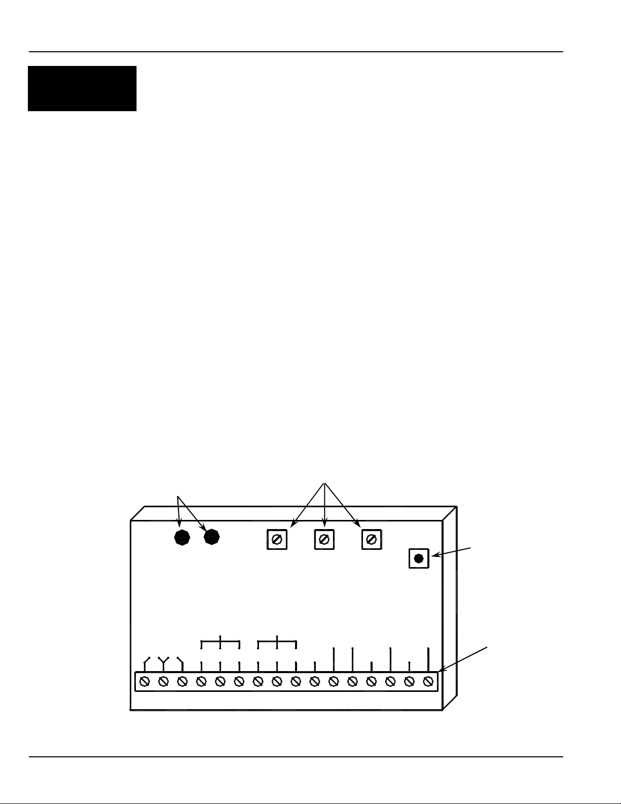
Refer to the Figure 1 below:
To enter the program mode, push and hold SW1 Mode Switch for 2 seconds. The mode that is presently
selected will be “flashed”.
Example: if the Multi-Module is in mode 3, the relays will click and the Indicator LEDs will flash 3 times. The user
now has 3 seconds to press the mode select button again to select the next mode. Pressing the button again
within 3 seconds will advance programming to the next mode. This newly selected mode will be flashed by the
relays and LEDs.
Example: the board is in mode 3 and the button is pressed for more than 2 seconds. The LEDs will flash 3 times.
To advance to the next mode the switch is again pressed within 3 seconds. The relays and LEDs flash 4 times
and mode 4 is now selected. Repeat this action until the desired mode is reached. When the desired mode is
reached and the mode select button remains off for 3 seconds the last mode that was “flashed” will be the mode
that is now selected. Power outages will not delete the selected mode.
The installer must ensure that all codes and standards are adhered to. Instruct the owner on door system operation and how to test it. Doors should be checked on a daily basis to ensure safe operation. Strongly
recommend that system be inspected on a yearly basis by an AAADAM certified technician.
Indicator LEDs
Figure 1 - Multi-Module
Potentiometers
SW1 Mode Switch
RL1 RL2
iti-200S
LEDLED
RELAY 1
ON TIME
DOO
(DELAY
ON
OPERATE)
RELAY 2
RELAY 2
ON TIME
SW 1
MODE
SWITCH
RELAY1 RELAY2
24V 12V
Page 6 www.NabcoEntrances.com 5-7-10
N.O. COM N.C. N.C.COMN.O. WET1
WET
DRY
COM COM
WET2 WET3
DRY1 DRY2
Terminal Strip
DN 0302
Page 7 www.NabcoEntrances.com 5-7-10
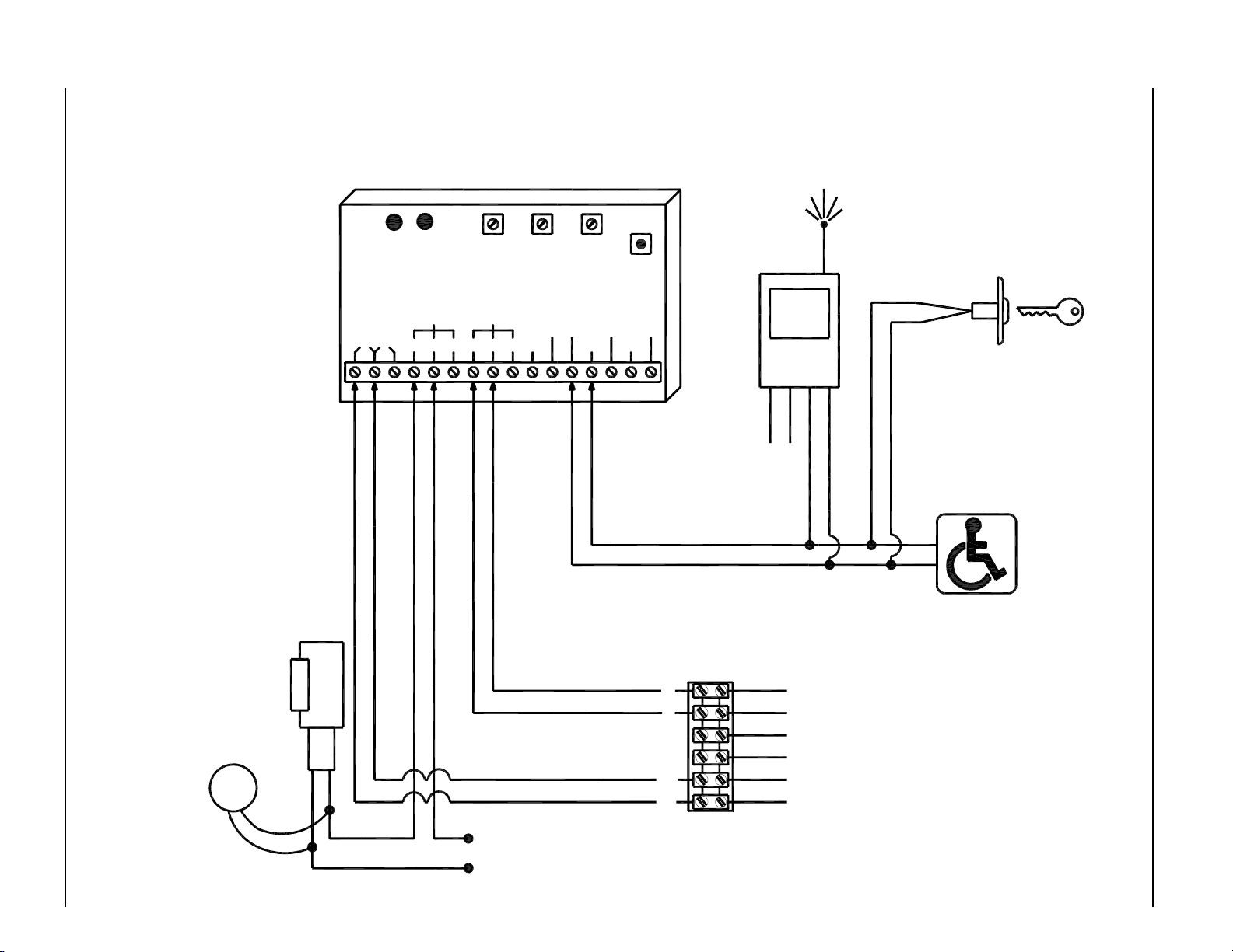
MODE 1 - ELECTRIC STRIKE SEQUENCER DIAGRAM - MAGNUM 4 CONTROL
Note:
1. A black circle indicates
a wire connection.
2. Power supply inputs not
polarity sensitive.
3. Multi-Module must be
set to Mode 1
If magnetic
lock or fail safe
strike used,
connect lock
ELECTRIC
STRIKE
wires to COM
and N.C.
terminals of
Multi-Module
TVS
Connect Transient
Voltage Suppressor
(supplied)
directly to strike.
Not polarity sensitive.
iti-200S
24V 12V
MULTI MODULE
RL1 RL2
LEDLED
RELAY1 RELAY2
N.O. C OM N.C. N.C.COMN.O. WET1
RELAY 1
ON TIME
PN 14-12240
RELAY 2
DOO
ON
WET
COM COM
ON TIME
DRY
DRY1 DRY2
(DELAY
OPERATE)
RELAY 2
STRIKE POWER
(To match strike
voltage)
SW 1
MODE
SWITCH
WET2 WET3
(IF USED)
RADIO
RECEIVER
4-TERM
N.O.
Power
6
5
4
3
2
1
BLACK
RED
WHITE
VIOLET
ORANGE
BROWN
COM
Power
Terminal Strip on Magnum Control
EXTERIOR KEY SWITCH
Normally Open - Dry Contacts
INTERIOR PUSH SWITCH
Normally Open - Dry Contacts
Nabco Multi-Module
DN 0302

Page 8 www.NabcoEntrances.com 5-7-10
Nabco Multi-Module
MODE 1 - ELECTRIC STRIKE SEQUENCER DIAGRAM - ANALOG CONTROL
Note:
1. A black circle indicates
a wire connection.
2. Power supply inputs not
polarity sensitive.
24 VAC120 VAC
Transformer
P/N 14-2101
24 VAC
If magnetic
lock or fail safe
strike used,
connect lock
ELECTRIC
STRIKE
wires to COM
and N.C.
terminals of
Multi-Module
iti-200S
LED LED
12V24V
RL2RL1
RELAY 1
ON TIME
RELAY2RELAY1
DOO
(DELAY
ON
OPERATE)
RELAY 2
WET
WET1N.O. C OM N.C.N.C.COMN.O.
RELAY 2
ON TIME
DRY
COMCOM
SW 1
MODE
SWITCH
WET3WET2
DRY2DRY1
(IF USED)
RADIO
RECEIVER
4-TERM
Power
Power
N.O.
COM
EXTERIOR KEY SWITCH
Normally Open - Dry Contacts
INTERIOR PUSH SWITCH
Normally Open - Dry Contacts
BLACK
RED
Activation Connector on Analog Control
TVS
Connect Transient
Voltage Suppressor
(supplied)
directly to strike.
Not polarity sensitive.
STRIKE POWER
(To match strike
voltage)
DN 0302

Page 9 www.NabcoEntrances.com 5-7-10
MODE 1 - BI-DIRECTIONAL DOOR SEQUENCER DIAGRAM - MAGNUM 4 CONTROL
RL1 RL2
LEDLED
iti-200S
RELAY1 RELAY2
24V 12 V
N.O. COM N.C. N .C.COMN.O. WET1
RELAY 1
ON TIME
DOO
(DELAY
ON
OPERATE)
RELAY 2
WET
COM COM
RELAY 2
ON TIME
DRY
DRY1 DRY2
SW 1
MODE
SWITCH
WET2 WE T3
INTERIOR PUSH SWITCH
Normally Open - Dry Contacts
EXTERIOR PUSH SWITCH
Normally Open - Dry Contacts
BLACK
RED
WHITE
VIOLET
ORANGE
BROWN
Terminal Strip on
Exterior Magnum
Control
OPTIONAL VESTIBULE PUSH SWITCH
Normally Open - Dry Contacts
6
5
4
3
2
1
BLACK
VIOLET
ORANGE
BROWN
Terminal Strip on
Interior Magnum
Control
RED
WHITE
NOTE:
1. When the module is triggered
by push switch (DRY1)
Relay # 1 will activate
first, then after an adjustable
delay, Relay # 2 will activate.
When the module is triggered
by the push switch (DRY2)
Relay # 2 will activate
first, then after an adjustable
delay, Relay # 1 will activate.
2. A black circle indicates a
wire connection.
3. Power supply inputs not
polarity sensitive.
DN 0302
Nabco Multi-Module

Page 10 www.NabcoEntrances.com 5-7-10
Nabco Multi-Module
MODE 1 - BI-DIRECTIONAL DOOR SEQUENCER DIAGRAM - ANALOG CONTROL
RL2RL1
LED LED
iti-200S
12V24V
24 VAC120 VAC
Transformer
P/N 14-2101
24 VAC
BLACK
RED
Activation Connector
on Exterior Analog
Control
RELAY 1
ON TIME
RELAY2RELAY1
DOO
ON
WET
RELAY 2
ON TIME
DRY
COMCOM
BLACK
RED
(DELAY
OPERATE)
RELAY 2
WET1N.O. COM N.C.N.C.COMN.O.
Activation Connector
on Interior Analog
SW 1
MODE
SWITCH
WET3WET2
DRY2DRY1
Control
INTERIOR PUSH SWITCH
Normally Open - Dry Contacts
EXTERIOR PUSH SWITCH
Normally Open - Dry Contacts
NOTE:
1. When the module is triggered
by push switch (DRY1)
Relay # 1 will activate
first, then after an adjustable
delay, Relay # 2 will activate.
When the module is triggered
by the push switch (DRY2)
Relay # 2 will activate
first, then after an adjustable
delay, Relay # 1 will activate.
2. A black circle indicates a
wire connection.
3. Power supply inputs not
polarity sensitive.
OPTIONAL VESTIBULE PUSH SWITCH
Normally Open - Dry Contacts
DN 0302
Page 11 www.NabcoEntrances.com 5-7-10
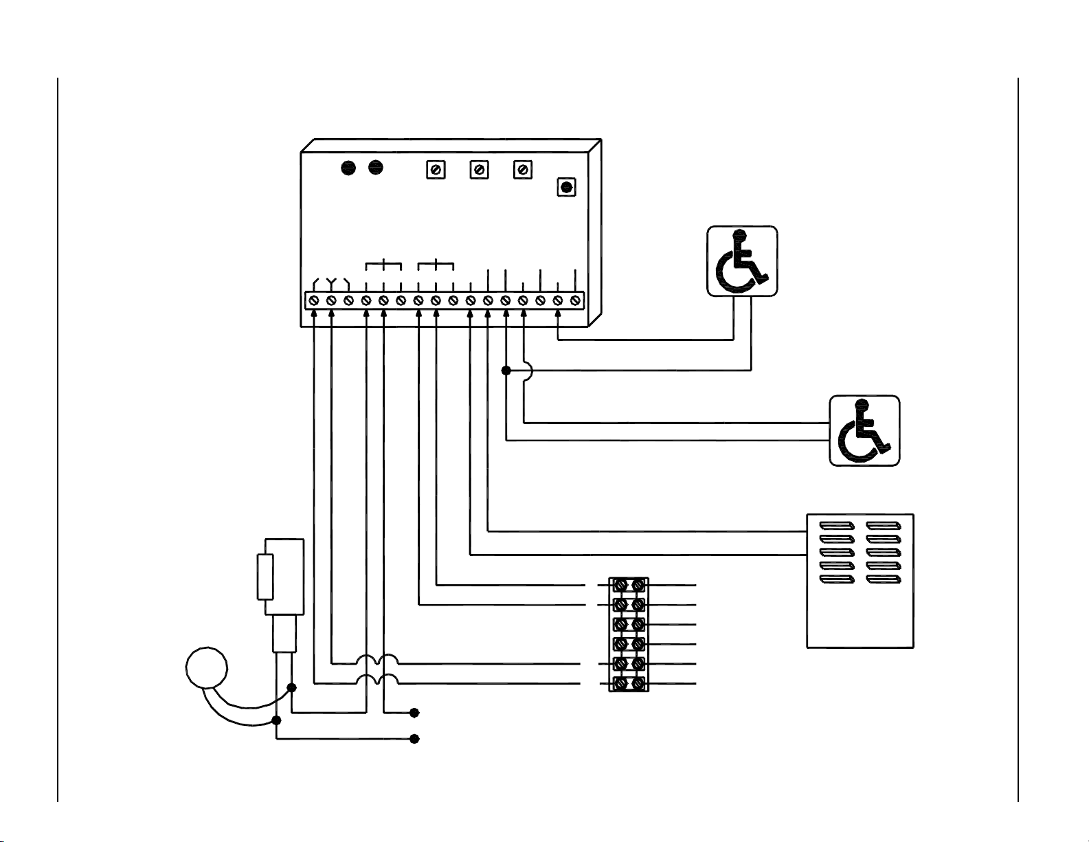
MODE 2 - APARTMENT OR ACCESS CONTROL DIAGRAM - MAGNUM 4 CONTROL
RL2RL1
LED LED
iti-200S
12V24V
RELAY 1
ON TIME
RELAY2RELAY1
DOO
(DELAY
ON
OPERATE)
RELAY 2
WET
WET1N.O. COM N.C.N.C.COMN.O.
RELAY 2
ON TIME
DRY
COMCOM
SW 1
MODE
SWITCH
WET3WET2
DRY2DRY1
Exterior Switch
(Only active when someone "buzzes
down") Switch opens door.
Normally Open - Dry Contacts
Interior Switch
Unlocks and opens door
Normally Open - Dry Contacts
If magnetic
lock or fail safe
strike used,
connect lock
wires to COM
and N.C.
terminals of
Multi-Module
Connect Transient
Voltage Suppressor
(supplied)
directly to strike.
Not polarity sensitive.
ELECTRIC
STRIKE
TVS
STRIKE POWER
(To match strike
voltage)
EXISTING LOCK POWER
6
5
4
3
2
1
BLACK
RED
WHITE
VIOLET
ORANGE
BROWN
Terminal Strip on
Magnum Control
Apartment
Interphone Panel
(Powered
Signal)
Unlocks door
only
Nabco Multi-Module
DN 0302

Page 12 www.NabcoEntrances.com 5-7-10
Nabco Multi-Module
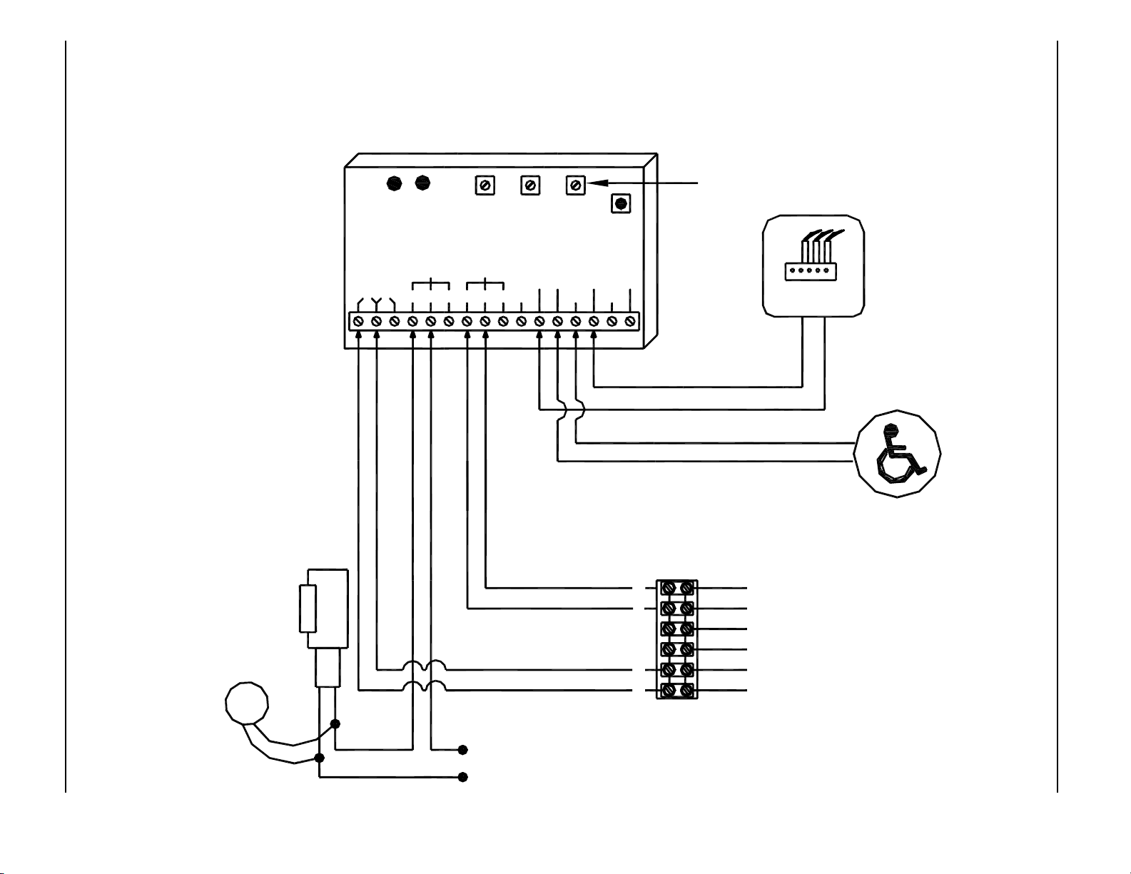
MODE 2 - APARTMENT OR ACCESS CONTROL DIAGRAM - ANALOG CONTROL
RL1 RL2
Transformer
P/N 14-2101
24 VAC
If magnetic
lock or fail safe
strike used,
connect lock
wires to COM
and N.C.
terminals of
Multi-Module
Connect Transient
Voltage Suppressor
(supplied)
directly to strike.
Not polarity sensitive.
24 VAC120 VAC
ELECTRIC
STRIKE
TVS
iti-200S
24V 12V
LEDLED
RELAY1 RELAY2
N.O. COM N.C. N.C.COMN.O. WET1
RELAY 1
ON TIME
(DELAY
OPERATE)
RELAY 2
STRIKE POWER
(To match strike
voltage)
DOO
ON
WET
DRY
COM COM
RELAY 2
ON TIME
DRY1 DRY2
SW 1
MODE
SWITCH
WET2 WET3
EXISTING LOCK POWER
BLACK
RED
Activation Connector on Analog Control
Exterior Switch
(Only active when someone "buzzes
down") Switch opens door.
Normally Open - Dry Contacts
Interior Switch
Unlocks and opens door
Normally Open - Dry Contacts
Apartment
Interphone Panel
(Powered
Signal)
Unlocks door
only
DN 0302

Page 13 www.NabcoEntrances.com 5-7-10
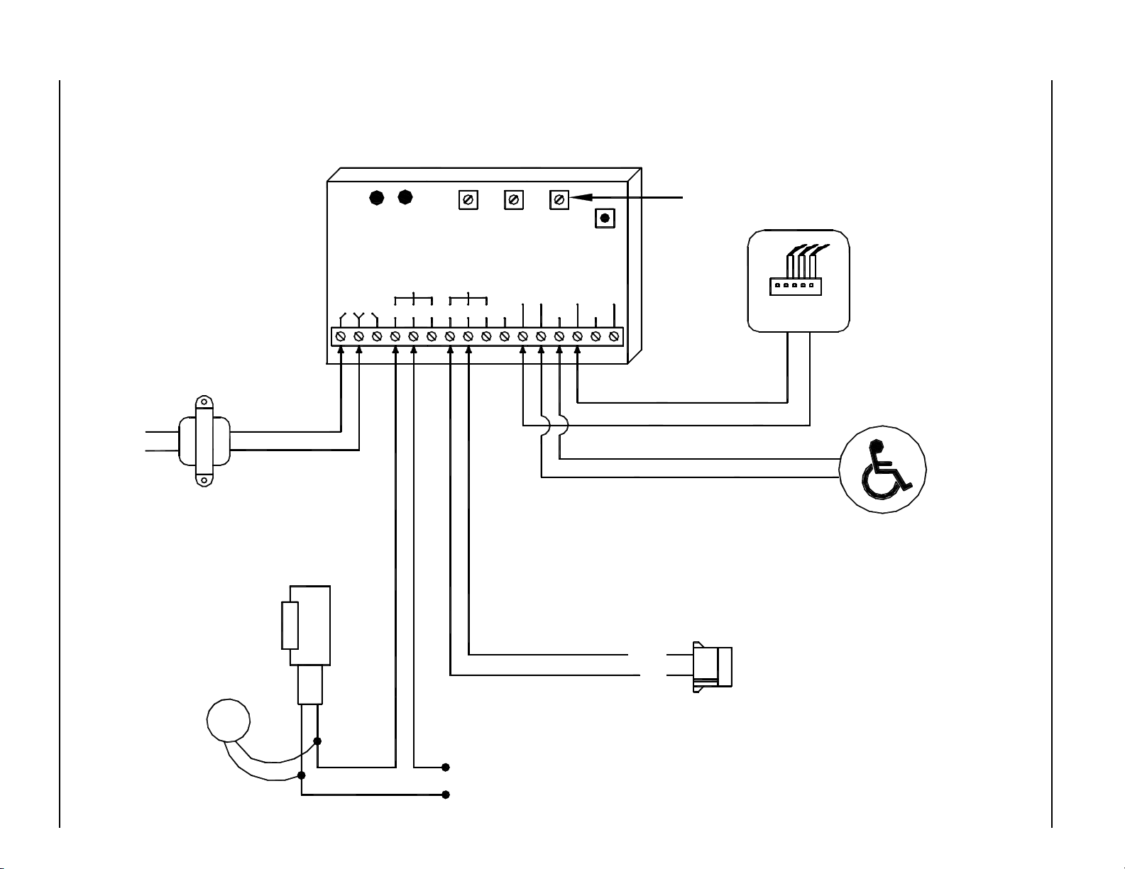
MODE 3 - RATCHET OR LATCHING OPERATION DIAGRAM - ANALOG CONTROL
Mode 3 not required with Magnum control - Magnum control includes this feature
NOTES:
1. Pushing either switch once
unlocks and opens door.
2. Door will remain open until
switch is pushed again.
3. This mode only used with
Analog control. Magnum and
U series controls have this
feature built in.
4. A black circle indicates a
wire connection.
5. Power supply inputs not
polarity sensitive.
24 VAC120 VAC
Transformer
P/N 14-2101
24 VAC
If magnetic
lock or fail safe
strike used,
connect lock
wires to COM
and N.C.
ELECTRIC
STRIKE
terminals of
Multi-Module
iti-200S
LED LED
12V24V
This potentiometer has no effect
RL2RL1
RELAY 1
ON TIME
RELAY2RELAY1
DOO
(DELAY
ON
OPERATE)
RELAY 2
WET
WET1N.O. COM N.C.N.C.COMN.O.
RELAY 2
ON TIME
DRY
COMCOM
SW 1
MODE
SWITCH
WET3WET2
DRY2DRY1
Interior Switch
Normally Open - Dry Contacts
Exterior Switch
Normally Open - Dry Contacts
BLACK
RED
Nabco Multi-Module
Connect Transient
Voltage Suppressor
(supplied)
directly to strike.
Not polarity sensitive.
TVS
Activation Connector on Analog Control
STRIKE POWER
(To match
strike voltage)
DN 0302

Page 14 www.NabcoEntrances.com 5-7-10
DN 0302
MODE 4 - ELECTRIC STRIKE DIAGRAM WITH HOLD OPEN SWITCH - MAGNUM 4 CONTROL
Note:
1. A black circle indicates
a wire connection.
2. Power supply inputs not
polarity sensitive.
3. Multi-Module must be set
to Mode 4.
If magnetic
lock or fail safe
strike used,
connect lock
ELECTRIC
STRIKE
wires to COM
and N.C.
terminals of
Multi-Module
TVS
Connect Transient
Voltage Suppressor
(supplied)
directly to strike.
MULTI MODULE
RL1 RL2
LEDLED
iti-200S
RELAY1 RELAY2
24V 12V
N.O. COM N.C. N.C.COMN.O. WET1
PN 14-12240
RELAY 1
ON TIME
DOO
(DELAY
ON
OPERATE)
RELAY 2
WET
COM COM
STRIKE POWER
(To match strike
voltage)
RELAY 2
ON TIME
DRY
DRY1 DRY2
SW 1
MODE
SWITCH
WET2 WET3
On/Off/Hold Open
Rocker Switch
WHITE
6
5
4
3
2
1
RED
BLACK
BLACK
RED
WHITE
VIOLET
ORANGE
BROWN
Terminal Strip on Magnum Control
EXTERIOR KEY SWITCH
(IF USED)
RADIO
RECEIVER
4-TERM
Power
Power
N.O.
Normally Open - Dry Contacts
COM
INTERIOR PUSH SWITCH
Normally Open - Dry Contacts
Nabco Multi-Module
Page 15 www.NabcoEntrances.com 5-7-10
Nabco Multi-Module
MODE 4 - SMOKE EVACUATION DIAGRAM - MAGNUM 4 CONTROL
NOTES:
1. In smoke evacuation or
maintained operator mode the
module can be triggered by a
wet input or a dry contact like a
sensor or any other relay
contact.
2. A black circle indicates a
wire connection.
3. Common and N.O. on
Acusensor 1B are Yellow wires.
4. Power supply inputs not
polarity sensitive.
iti-200S
LED LED
12V24V
RL2RL1
RELAY 1
ON TIME
RELAY2RELAY1
DOO
(DELAY
ON
OPERATE)
RELAY 2
WET
WET1N.O. COM N.C.N.C.COMN.O.
RELAY 2
ON TIME
DRY
COMCOM
SW 1
MODE
SWITCH
WET3WET2
DRY2DRY1
This potentiometer has no effect
FIRE
Fire Alarm Panel
Shown with maintained
and powered signal (WET)
12-24V AC/DC
If magnetic
lock or fail safe
strike used,
connect lock
wires to COM
and N.C.
terminals of
Multi-Module
Connect Transient
Voltage Suppressor
(supplied)
directly to strike.
Not polarity sensitive.
ELECTRIC
STRIKE
TVS
STRIKE POWER
(To match
strike voltage)
6
5
4
3
2
1
VIOLET
ORANGE
Terminal Strip on
Magnum Control
PUSH SWITCH
Normally Open - Dry Contacts
BLACK
RED
WHITE
BROWN
DN 0302
Page 16 www.NabcoEntrances.com 5-7-10
MODE 4 - SMOKE EVACUATION DIAGRAM - ANALOG CONTROL
NOTES:
1. In smoke evacuation or
maintained operator mode the
module can be triggered by a
wet input or a dry contact like a
sensor or any other relay
contact.
2. A black circle indicates a
wire connection.
3. Common and N.O. on
Acusensor 1B are Yellow wires.
4. Power supply inputs not
polarity sensitive.
120 VAC 24 VAC
iti-200S
24V 12V
RL1 RL 2
LEDLED
RELAY1 RELAY2
N.O. COM N.C. N.C.COMN.O. WET1
RELAY 1
ON TIME
DOO
(DELAY
ON
OPERATE)
RELAY 2
WET
COM COM
RELAY 2
ON TIME
DRY
DRY1 DRY2
SW 1
MODE
SWITCH
WET2 WET3
This potentiometer has no effect
FIRE
Fire Alarm Panel
Shown with maintained
and powered signal (WET)
12-24V AC/DC
Transformer
P/N 14-2101
24 VAC
If magnetic
lock or fail safe
strike used,
connect lock
wires to COM
and N.C.
terminals of
Multi-Module
Connect Transient
Voltage Suppressor
(supplied)
directly to strike.
Not polarity sensitive.
ELECTRIC
STRIKE
TVS
Activation Connector on Analog Control
STRIKE POWER
(To match
strike voltage)
PUSH SWITCH
Normally Open - Dry Contacts
BLACK
RED
Nabco Multi-Module
DN 0302
Page 17 www.NabcoEntrances.com 5-7-10
Nabco Multi-Module
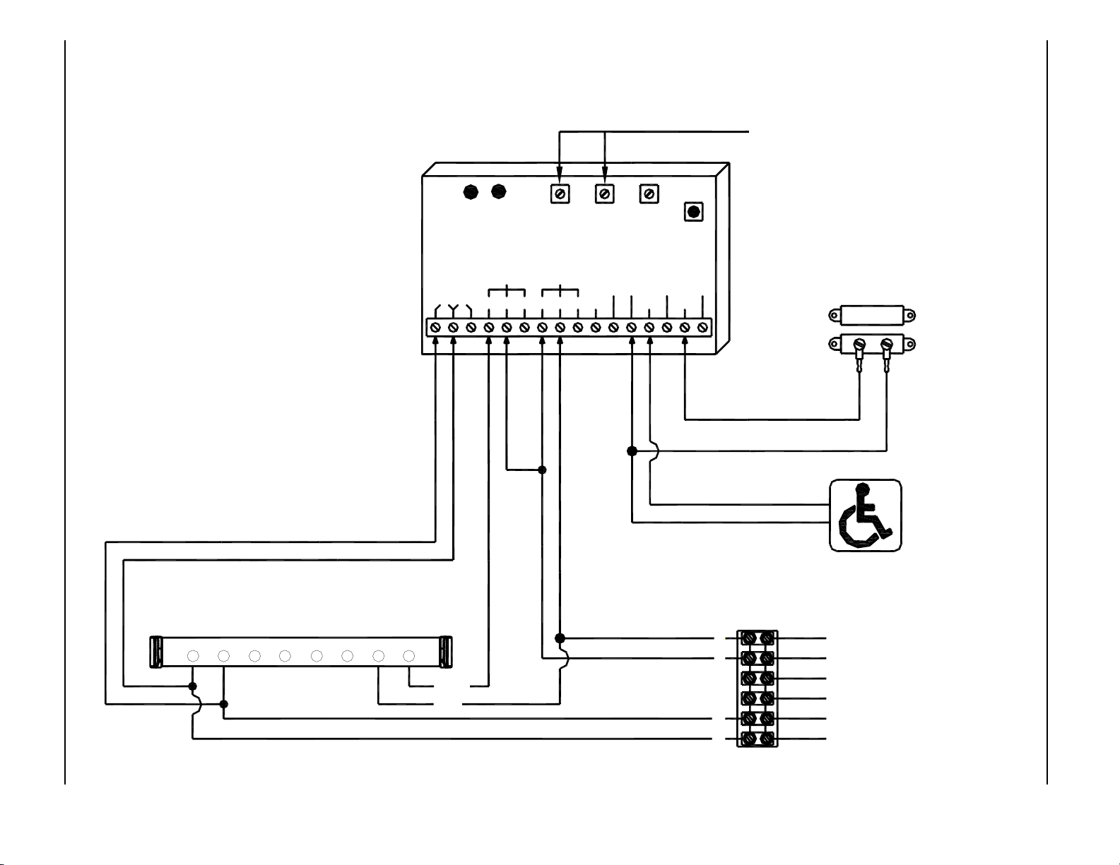
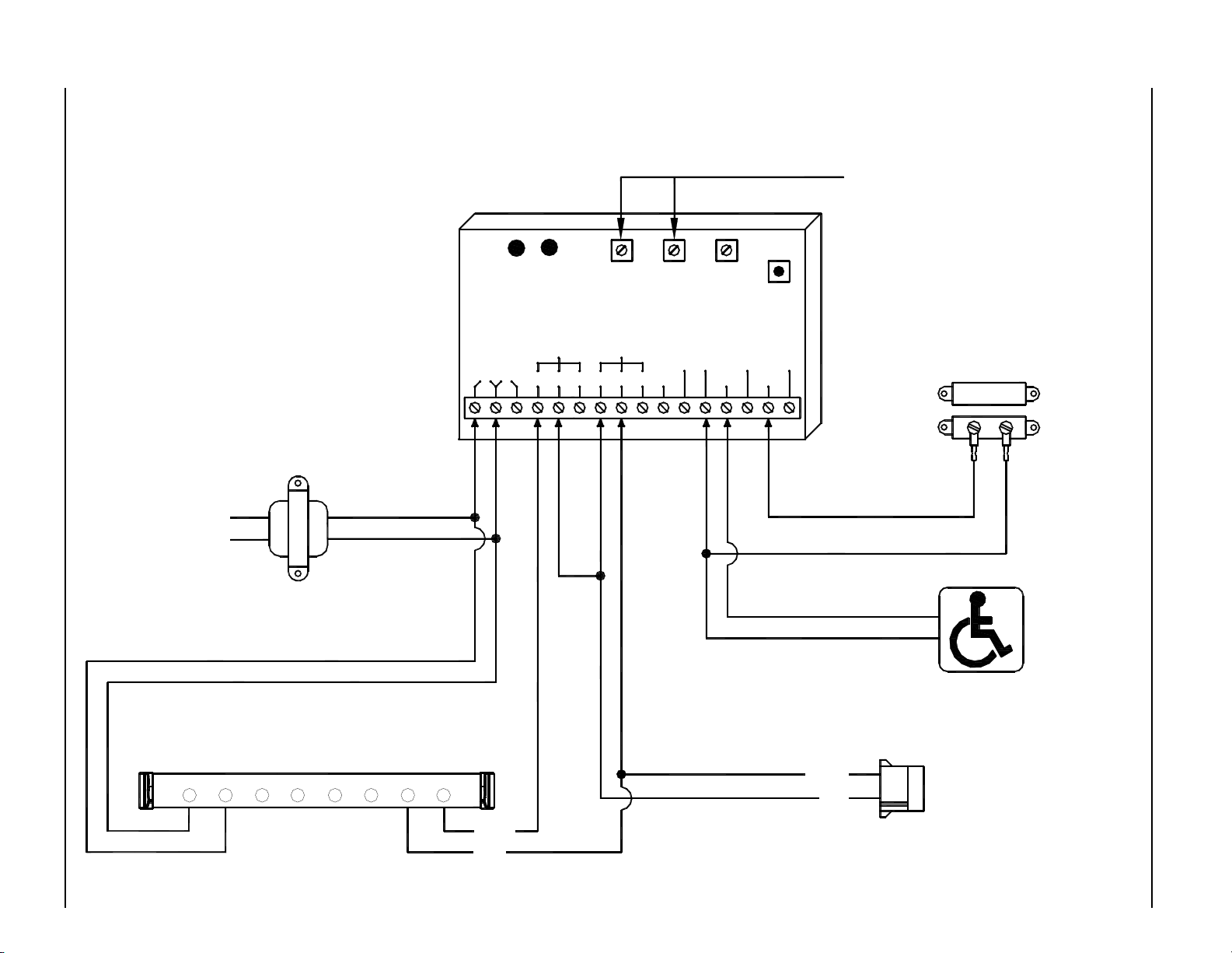
MODE 5 - ACUGARD LOCK OUT RELAY DIAGRAM - MAGNUM 4 CONTROL
These Potentiometers have no effect
DN 0302
NOTES:
1. Sensor only active after push
plate is actuated. It will stay
active until the door shuts and
door position switch closes.
Multi-Module will reset after 2
minutes if the door does not
open for any reason.
2. A black circle indicates a
wire connection.
3. Power supply inputs not
polarity sensitive.
Acugard 3 LE on Non-swing side of door
P/N 21-10158-35
RL1 RL2
iti-200S
24V 12V
LEDLED
RELAY1 RELAY2
N.O. COM N.C. N.C.COMN.O. WET1
RELAY 1
ON TIME
DOO
(DELAY
ON
OPERATE)
RELAY 2
WET
COM COM
RELAY 2
ON TIME
DRY
DRY1 DRY2
SW 1
MODE
SWITCH
WET2 WET3
Magnetic Door Position Switch
P/N 14-11313
Contacts should close when door is
closed - Connect to COM and N.O.
terminals on switch.
Activation Push Plate
Normally Open - Dry Contacts
6
87654321
COM
N.O
5
4
3
2
1
BLACK
RED
WHITE
VIOLET
ORANGE
BROWN
Terminal Strip on Magnum Control
Page 18 www.NabcoEntrances.com 5-7-10
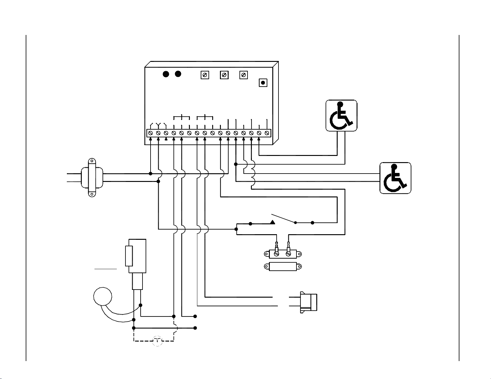
MODE 5 - ACUGARD LOCK OUT RELAY DIAGRAM - ANALOG CONTROL
These Potentiometers have no effect
NOTES:
1. Sensor only active after push
plate is actuated. It will stay
active until the door shuts and
door position switch closes.
Multi-Module will reset after 2
minutes if the door does not
open for any reason.
2. A black circle indicates a
wire connection.
3. Power supply inputs not
polarity sensitive.
120 VAC 24 VAC
iti-200S
LED LED
12V24V
RL2RL1
RELAY 1
ON TIME
RELAY2RELAY1
DOO
(DELAY
ON
OPERATE)
RELAY 2
WET
WET1N.O. COM N.C.N.C.COMN.O.
RELAY 2
ON TIME
DRY
COMCOM
SW 1
MODE
SWITCH
WET3WET2
DRY2DRY1
Magnetic Door Position Switch
P/N 14-11313
Contacts should close when door is
closed - Connect to COM and N.O.
terminals on switch.
Transformer
P/N 14-2101
24 VAC
Acugard 3 LE on Non-swing side of door
P/N 21-10158-35
1 2 3 4 5 6 7 8
COM
N.O
Activation Push Plate
Normally Open - Dry Contacts
BLACK
RED
Activation Connector on Analog Control
Nabco Multi-Module
DN 0302

Page 19 www.NabcoEntrances.com 5-7-10
Nabco Multi-Module
MODE 6 - WASHROOM CONTROL RELAY DIAGRAM - MAGNUM 4 CONTROL
NOTES:
1. Fail Safe Strike Used
2. A black circle indicates a
wire connection.
3. Power supply inputs not
polarity sensitive.
Connect Transient
Voltage Suppressor
(supplied)
directly to strike.
Not polarity sensitive.
DN 0302
ELECTRIC
STRIKE
Fail Safe
TVS
LED LED
iti-200S
12V24V
Optional Occupied Light
RL2RL1
STRIKE POWER
(To match strike
voltage)
RELAY 1
ON TIME
RELAY2RELAY1
DOO
(DELAY
ON
OPERATE)
RELAY 2
WET
WET1N.O. COM N.C.N.C.COMN.O.
RELAY 2
ON TIME
DRY
COMCOM
SW 1
MODE
SWITCH
WET3WET2
DRY2DRY1
Push to Lock Switch
Magnetic Door Position Switch
P/N 14-11313
Interior Push Plate
Normally Open - Dry Contacts
Exterior Push Plate
Normally Open - Dry Contacts
Contacts close when door is closed
Connect to COM and N.O. terminals on switch.
6
5
4
3
2
1
BLACK
RED
WHITE
VIOLET
ORANGE
BROWN
Terminal Strip on Magnum Control
Page 20 www.NabcoEntrances.com 5-7-10
MODE 6 - WASHROOM CONTROL RELAY DIAGRAM - ANALOG CONTROL
NOTES:
1. Fail Safe Strike Used
2. A black circle indicates a
wire connection.
3. Power supply inputs not
polarity sensitive.
Transformer
P/N 14-2101
24 VAC
ELECTRIC
STRIKE
Fail Safe
Connect Transient
Voltage Suppressor
TVS
(supplied)
directly to strike.
Not polarity sensitive.
iti-200S
24V 12V
RL1 RL2
LEDLED
RELAY1 RELAY2
N.O. COM N.C. N.C.COMN.O. WET1
RELAY 1
ON TIME
DOO
(DELAY
ON
OPERATE)
RELAY 2
WET
COM COM
RELAY 2
ON TIME
DRY
DRY1 DRY2
SW 1
MODE
SWITCH
WET2 WET3
Interior Push Plate
Normally Open - Dry Contacts
Exterior Push Plate
Normally Open - Dry Contacts
24 VAC120 VAC
Push to Lock Switch
Contacts close when door is closed
Connect to COM and N.O. terminals on switch.
Magnetic Door Position Switch
P/N 14-11313
BLACK
RED
Activation Connector on Analog Control
Nabco Multi-Module
STRIKE POWER
(To match
strike voltage)
DN 0302
Optional Occupied Light

Nabco Multi-Module
NABCO Entrances Return Policy - Limited Warranty
NABCO ENTRANCES INC. for its Gyro Tech product line, provides to its distributor a limited warranty, on Gyro
Tech products. This warranty is:
NABCO ENTRANCES INC. will exchange or repair, F.O.B. the plant, any component found defective in
workmanship and/or material, subject to Nabco’s inspection, for a period of one (1) year after
installation or 18 months after manufacture, whichever comes first. Warranty does not include field
service labor. The installing contractor/distributor will be responsible for installation and field service.
This is NABCO ENTRANCES Inc.’s sole warranty.
This warranty does not cover loss or damages resulting from causes beyond the manufacturer's control,
misuse, neglect, accidents, windstorms, or other acts of God, or acts of terrorism. Warranty is for normal use
and service. The warranty does not apply to equipment that has been repaired or altered so as to adversely
affect conditions of operation. Warranty will not obligate NABCO for damages resulting from such alterations,
misuse, or acts of God, or acts of terrorism.
Extended Warranties - New Parts and Equipment Only
Two-year warranties on all Gyro Tech entrance systems are available. The two (2) year warranty is the same
as the one (1) year warranty except for a period of two (2) years after installation or 30 months after
manufacture whichever comes first. All orders requesting a multi year warranty must be included on the
purchase order at the time of the original order to establish proper records. Any other extended warranty must
be specifically approved and priced by NABCO Management.
Warranty Seal on Operators
All operators will contain a warranty seal placed over the cover and housing. The warranty will become invalid if
any operator is returned with the seal broken.
Return of Warranty Parts
NABCO must be promptly notified (within 2 weeks of failure) of all warranty claims. All parts for warranty claims
must be returned to NABCO within the following two (2) weeks for US locations and six (6) weeks for all other
locations. All parts must be returned freight prepaid and include a Return Material Authorization Tag/Number
which is available by contacting the Customer Service Department. All items returned are subject to inspection
and testing to determine the cause of failure. If in NABCO's determination:
A. For all items, when the part returned is defective and within the terms of the warranty, it will be repaired or
replaced. Any repaired item would carry the full warranty from original installation date. If the piece has been
replaced, a credit memo will be issued against the replacement invoice. Warranty parts are shipped prepaid via
ground transportation by Nabco. Expedited delivery costs are paid by the distributor.
B. For all items, if it is determined the part returned is not defective and within the terms of the warranty the
part will remain the property of the Distributor at the time of this determination. The disposition of the item will
be agreed upon with the distributor. The only options considered will be:
1. To return the item at the distributor cost.
2. To return it to stock less inspection and testing costs if the piece has not been used
and remains saleable as a new part. A 20% restocking charge will apply and be paid
by the distributor.
3. Discarded by NABCO.
Non-warranty Returns
Applications for the return and credit of any parts item must be made in writing to Nabco Customer Service
within 60 days of the date of our shipment. Only items listed on attached Nabco RMT tags will be considered.
Parts that have been ordered incorrectly can be exchanged for the correct items provided Nabco Customer
Service is notified in writing within 60 days of the date of our shipment and subsequent return authorization has
been given. Credit for parts that have been ordered by the distributor and are no longer needed for repair in the
field will be subject to the discretion of Nabco. A 20% stocking fee will apply.
Page 21 www.NabcoEntrances.com 5-7-10
 Loading...