

Page 1
Automatic
Entrance
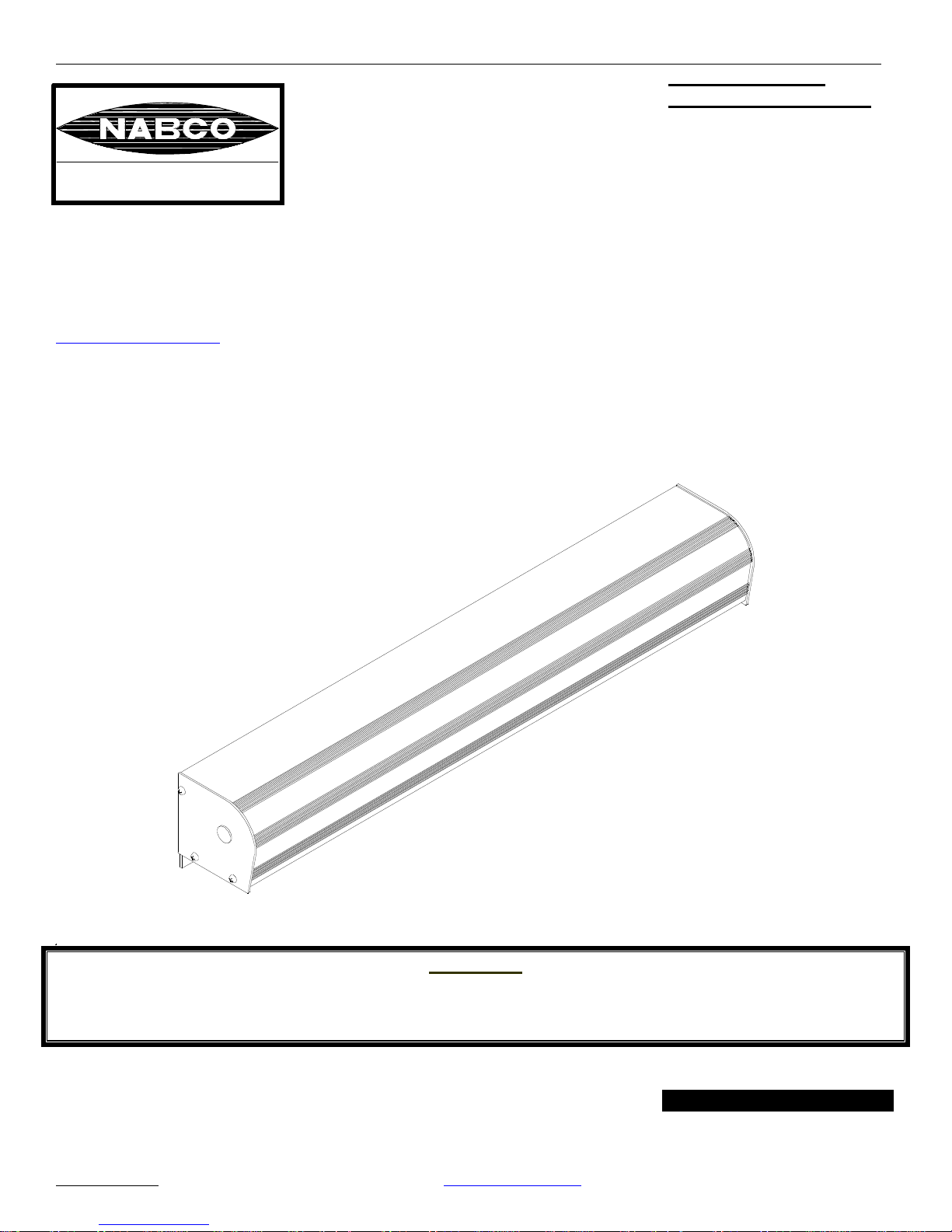
Model 710 Swing Door System
Magnum Board IV.
Retrofit kit (Old Casting)
G Y R O T E C H
NABCO ENTRANCES Inc.
S82 W18717 Gemini Drive
P.O. Box 906
Muskego, WI 53150
Phone: 877-622-2694
Fax: 888-679-3319
www.nabcoentrances.com
Model 710 Swing Door System
Systems
Retrofit Kit Manual
Low Energy Operator
DN0011
Do not install, operate or service this product unless you have read and understand the Safety Practices,
Warnings, Installation and Operating Instructions contained in this manual. Failure to do so may result
Part Number 15-10677
August 23, 2004 Revision INSTALLATION MANUAL
NABCO
ENTRANCES INC 877-622-2694 www.nabcoentrances.com
WARNING
in property damage, or bodily injury.
Page 2

Model 710 Swing Door System
CAUTION:
Read these safety practices before installing, operating or servicing the automatic door. Failure to follow
these practices may result in serious consequences.
Read, study and understand the operating instructions contained in or referenced in this manual before
operating. If you do not understand the instruction, ask the installing qualified technician to teach you
how to use the door.
This manual and the owners’ manual must be given to and retained by the purchasing facility or end
user.
1. If the door appears broken or does not seem to work correctly, it should be immediately removed
from service and a qualified service technician contacted for corrective action.
2. Disconnect power at the fused disconnect during all electrical or mechanical service. When uncertain
whether power supply is disconnected, always verify using a voltmeter.
3. All electrical troubleshooting or service must be performed by qualified electrical technicians and
must comply with all applicable governing agency codes.
4. It is the responsibility of the installing door technician to install all warning and instructional labels in
accordance with ANSI A156.19.
5. It is the responsibility of the purchasing facility or end user to keep warning and instructional labels
and literature legible, intact and with the door.
6. Replacement labels and literature may be obtained from local NABCO Entrances Inc. distributors.
If the name of the local distributor is unknown, contact NABCO Entrances Inc. at (877-622-2694)
for assistance.
7. Do not place finger or uninsulated tools inside the electrical control box. Touching wires or other
parts inside the enclosure may cause electrical shock, serious injury or death.
NABCO
ENTRANCES INC 877-622-2694 www.nabcoentrances.com - 2 -
Page 3

Model 710 Swing Door System
Contents
Overview 4
Specifications 5
Handing Requirements 6
Hardware Kit List 7~8
Magnet Switch Assembly 9
Single Door Conversion 10
Simultaneous Pair Conversion 11
Hydraulic Closer 12
Hydraulic Closer Adjustment 13
Setting Back Check and Door Closed Switches 14~18
Simultaneous Pair Installations 19
Control Switches 19
Signage 19
Troubleshooting 20
ANSI/BHMA Specs. 21-22
NABCO
ENTRANCES INC 877-622-2694 www.nabcoentrances.com - 3 -
Page 4
Model 710 Swing Door System
To The Installer The purpose of this manual is to familiarize the purchaser with the proper
installation and operation of this system. It is essential that this equipment be
properly installed and operational before the door is used by the public. It is the
purchaser’s responsibility to inspect the operation of the entrance system to be
sure it complies with any applicable standards. In the United States, ANSI
Standard 156.19 usually covers this type of door. Other local standards or codes
may apply. Use them in addition to the ANSI Standard. The GT 710 is listed
with the Underwriters Laboratory and is identified as such on the label.
Instruct the building owners/operator on the essentials of the operation of the door
and this device. The owner should follow these instructions to determine whether
the door is operating properly and should immediately call for service if there is
any malfunction.
All installation changes and adjustments must be made by qualified, NABCO
trained technicians.
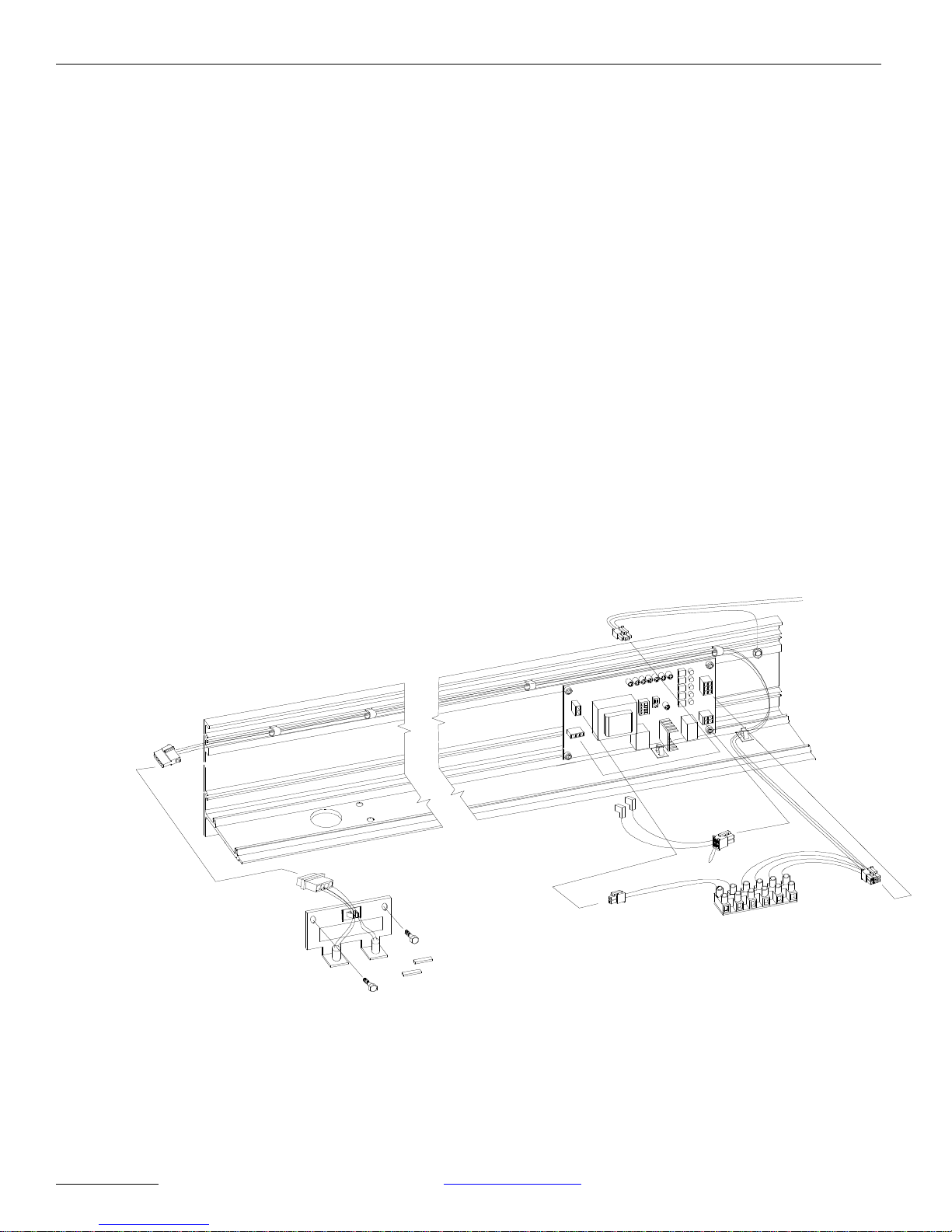
Overview Earlier version of the NABCO GT710 can be retrofitted with the newer Magnum
Control Board (Magnum IV). This combination offers several control features
that accommodate most installations.
DN0036
This Manual offers step-by-step instructions on how to upgrade an existing
GT710 installation with the Magnum IV and related hardware.
Figure 1 – Overview of GT710 with Magnum IV
NABCO
ENTRANCES INC 877-622-2694 www.nabcoentrances.com - 4 -
Page 5
Model 710 Swing Door System
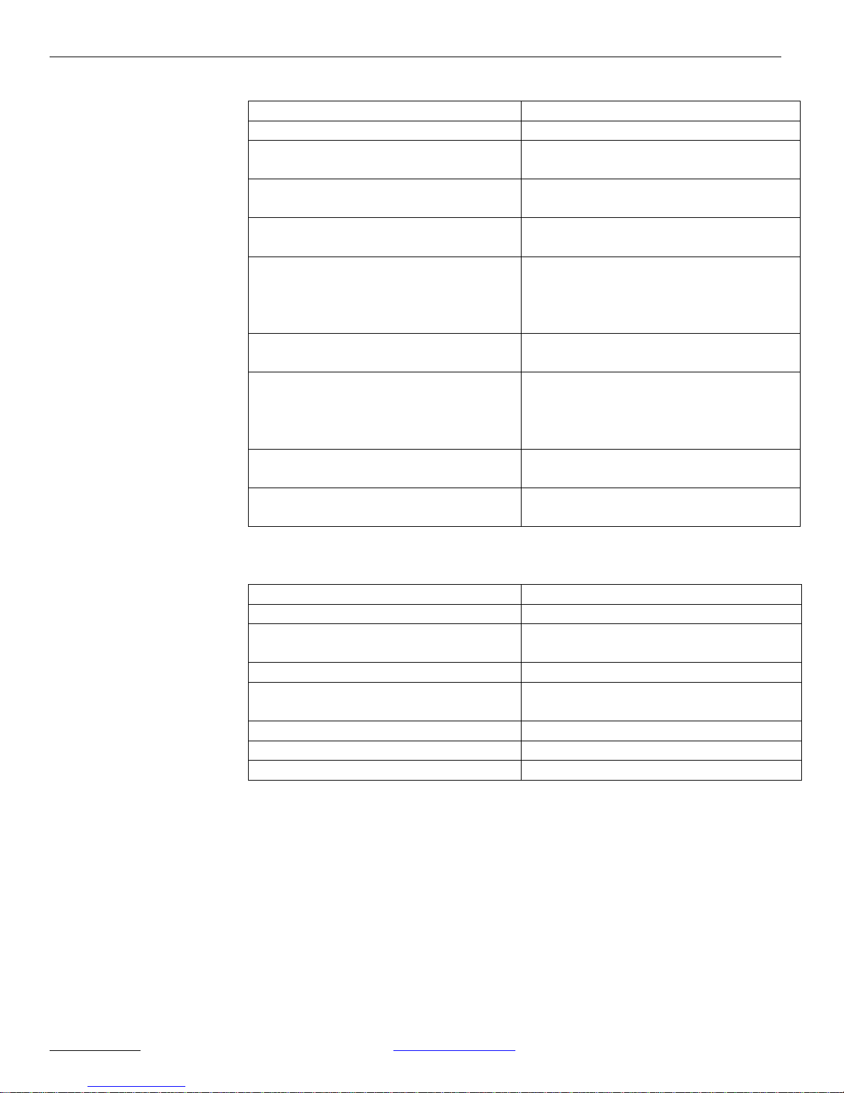
Table 1 – Comparison of Magnum IV to the original GT710 Controller
Magnum IV Board GT710 Controller
Adjustable opening speed. Adjustable opening speed.
Adjustable current limit/door block
trip.
Adjustable activation timer (0 to 60
seconds)
Adjustable separate push-n-go timer
Adjustable current limit/door block
trip.
One adjustable timer for activation and
push-n-go (0 to 60 seconds)
None
(0 to 60 seconds)
Adjustable door action when detection
No adjustment.
(continuous safety) occurs – allow
door to stop, creep open or creep
closed.
Automatic shut-off of motor if door
does not open within 30 seconds.
Connection provided for swing side
Shut-off occurs when the timer for
activation expired.
N/A
mats and swing side presence detector
(Continuous safety and safety with
lockout).
Enable/disable sequential operation
via dip switch.
Enable/disable push-n-go via dip
switch.
Enable/disable sequential operation via
onboard jumper.
Wiring change required to activate
push-n-go.
Specifications
Power Input 120 (±10%) AC 50-60 Hz, 5 Amps
Available current for Accessories 0.5 Amps 24 Volts AC
Available Wire Size for Incoming
Power
Minimum Frame Face for Mounting 1 ¾” (44 mm)
Minimum Clearance from Top of
Door to Ceiling
Door Hinge Requirements ¾” Butt, Offset Pivot, or Center Pivot
Door Thickness 1 ¾” (44 mm) Minimum
Door Width Specify When Ordering
Tools required 5/32” Hex Key (Allen Wrench)
Phillips Screwdriver #2
Slotted Screwdrivers, Small and Medium
Drill Bits: 11/64” and 7/8”
14 AWG
7” (178 mm)
NABCO
ENTRANCES INC 877-622-2694 www.nabcoentrances.com - 5 -
Page 6
Model 710 Swing Door System
Note:
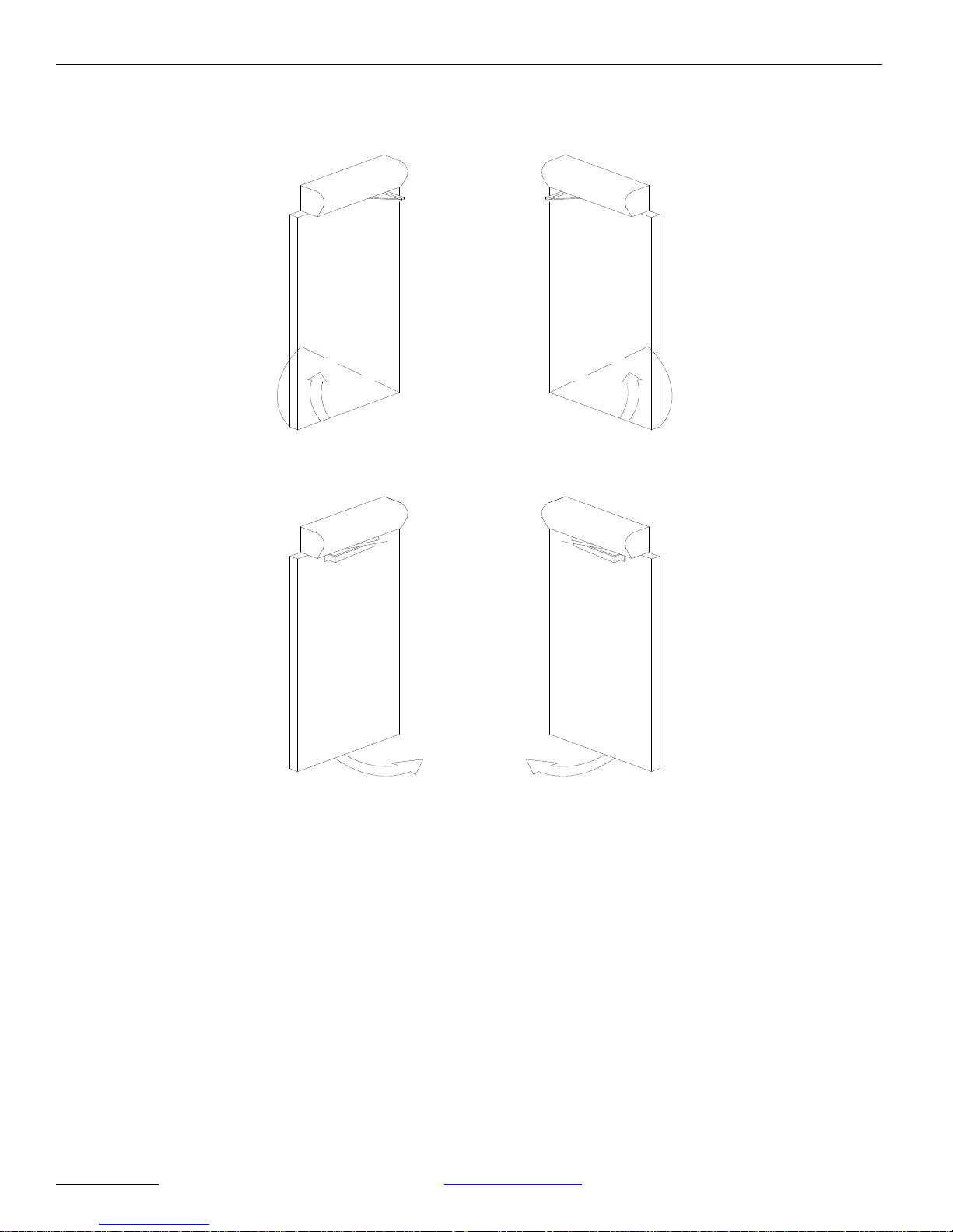
Handing Requirements The type of door will determine whether a left-hand or a right-hand operator is
required. Figure 2 can be used to determine which unit is required.
RIGHT HAND
OUT-SWING
(RH)
LEFT HAND
IN-SWING
(LH)
LEFT HAND
OUT-SWING
(LH)
RIGHT HAND
IN-SWING
(RH)
DN0015
The hand of the unit and the hand of the door must be the same. The
hand of the unit is not reversible and cannot be converted in the field.
NABCO
ENTRANCES INC 877-622-2694 www.nabcoentrances.com - 6 -
Figure 2 – Determine the Swing (Hand) of the Door.
Page 7
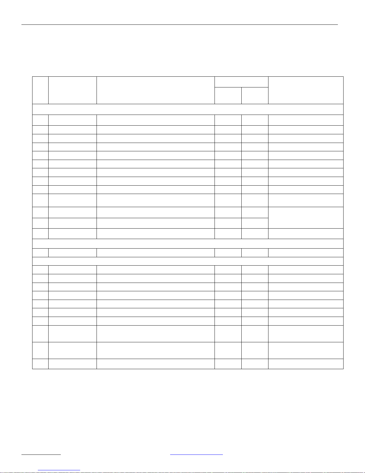
Hardware Kit List
This kit has been shipped with the following installation hardware.
MAGNUM IV RETRO FIT for SINGLE – P/N 11-10361-01
MAGNUM IV RETRO FIT for SIM.PAIR – P/N 11-10361-02
Model 710 Swing Door System
QtyPart # Part Description
Notes
Single Sim-
Pair
All items (#1~#24) would be packed into 8”x6”x6” box (P/N 14-1159).
1 24-9800-04 Magnum IV Control Board 1 2
2 22-10065 Main Harness - Single 1 --- With Terminal Block
3 22-10270 Main Harness – Simultaneous Pair --- 1 With Terminal Block
4 11-10286 Motor Harness 1 2 Four Pin Connector
5 21-9933 Power Harness - Single 1 --6 14-5883 Power Harness – Simultaneous Pair --- 1
7 11-10272 Rocker Switch Assy 1 1 No connector
8 21-9941-01 Magnetic Switch Assy - RH --- 1
9 21-9941-02 Magnetic Switch Assy - LH --- 1
10 21-10005 Magnetic Switch Plate Assy 1 ---
11 14-9940-01 Label for RH Operator 1 ---
Use one of Labels.
12 14-9940-02 Label for LH Operator 1 ---
13 15-10677 GT710 Retrofit Kit Manual 1 1
Packed into a 3”x4” ziplock bag (P/N 14-0828-01).
14 14-9944 Epoxy Package & Stir Stick 1 2
Packed into a 4”x6” ziplock bag (P/N 14-0828-03).
15 14-9960 Wire Saddle 3 6
16 24-1447 Wire Harness Clip 4 8
17 14-9959 Cable Clamp --- 4
18 14-9943 Ceramic Magnet 2 4
19 14-8743 Spacer for Magnum Board 4 8
20 14-1218 Wire Nut 2 4
21 14-1838 Male Pin Housing , 4 circuit 1 --- For Magnetic Switch
22 24-0011-014 #10-32x1/2” Phillips Black Oxide
2 2 For Rocker Switch
Screw
23 24-4941-19 3/8-16x3/4” Hex Washer Head Screw,
2 4 For Magnetic Switch
F
24 24-0010-01 #10-24x7/8” Socket Head Cap Screw 4 8 For Magnum Board
NABCO
ENTRANCES INC 877-622-2694 www.nabcoentrances.com - 7 -
Page 8
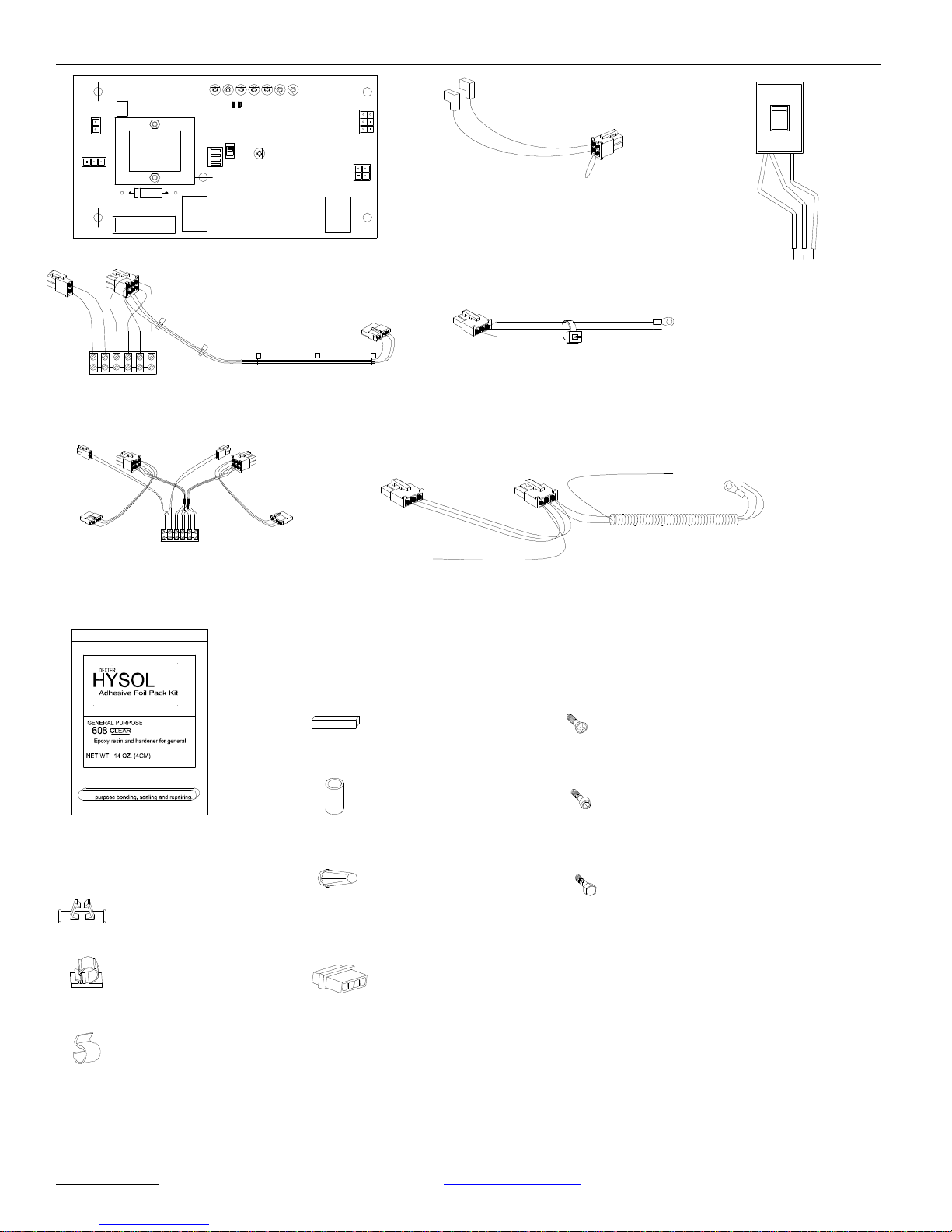
AUX
PWR
AC IN
J2
F1
Fuse 2: 0.5A 24 VAC
TRANSFORMER
CAPACITOR
F2
Fuse 1: 3A 120/240
R2
R3J4R4 R5 R6 R7 R8
TDAS
STOP OPEN BCHK
SW1
RELAY
MAGNUM IV
TDPG LCHK CLOSE
LED
R28
OFF
1 2
CURRENT
3
LIMIT
4
SW2
Magnum IV Board
P/N 24-9800-04
RELAY
SIGNAL
INPUT
MOTOR
J5
Model 710 Swing Door System
On
Off
Off
J1
Hold Open
Motor Harness
P/N 11-10286
Main Harness - Single
P/N 22-10065
Main Harness - Sim. Pair
P/N 22-10270
Epoxy and Stir Stick
Epoxy & Stir Stick
P/N 14-9944
Wire Saddle
P/N 14-9960
Wire Nut
(2)
1
Power Harness - Single
P/N 21-9933
Ceramic Magnet
P/N 14-9943
Spacer
for Magnum Board
P/N 14-8743
Wire Nut
P/N 14-1218
Rocker Switch Assy.
P/N 11-10272
Power Harness - Sim.Pair
P/N 14-5883
#10-32x1/2"
Phillips Head Black Oxide Screw
P/N 24-0011-014
3/8-16x3/4"
Hex Washer Head Screw, Type F
P/N 24-4941-19
#10-24x7/8"
Socket Head Cap Screw
P/N 24-0010-01
Cable Clamp
P/N 14-9959
Wire Harness Clip
P/N 24-1447
DN0037
NABCO
ENTRANCES INC 877-622-2694 www.nabcoentrances.com - 8 -
Male Pin Housing
4 circuit
P/N 14-1838
Figure 3 – Installation Hardware
Page 9
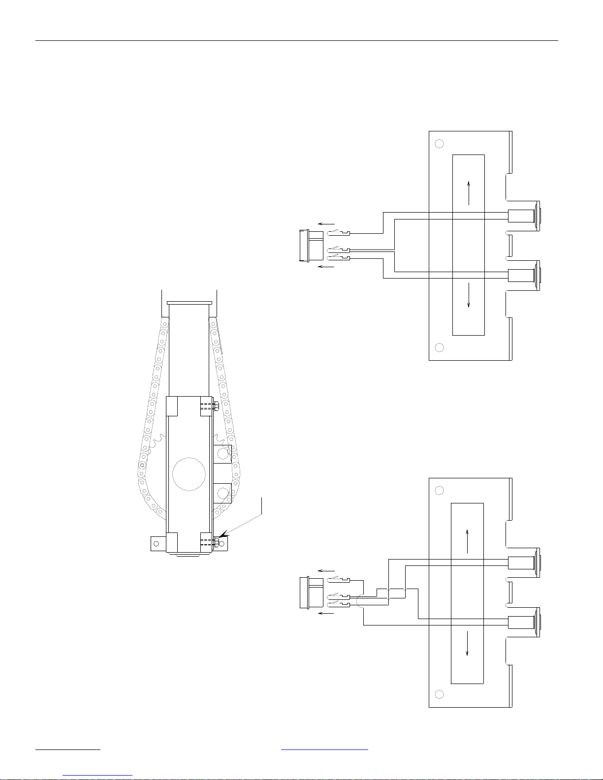
Magnetic Switch
Model 710 Swing Door System
Door
Switch
Left Hand
P/N 21-9941-02
Closed
R/L
3
4 2 1124
5/16-18 x 3/4" Hex Washer Head, Type F
P/N 24-4941-19
Magnetic Switch
Right Hand
P/N 21-9941-01
For
Units
LEFT HAND
Check
Switch
Back
Back
Check
Switch
Mounting Magnetic Switch subassy
NABCO
ENTRANCES INC 877-622-2694 www.nabcoentrances.com - 9 -
3
Figure 4 – Magnetic Switch assembly
For
Units
RIGHT HAND
Closed
Switch
Door
DN0038
Page 10
SCREWS & SPACERS
Model 710 Swing Door System
WIRE SADDLE
P/N 14-9960
P/N 24-4941-16 & 14-8743
MAIN HARNESS
P/N 22-10065
MAGNUM IV BOARD
P/N 24-8900-04
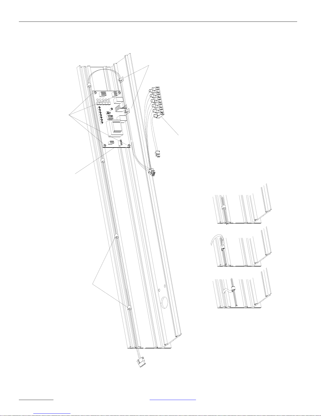
SINGLE DOOR CONVERSION of GT710
2. Push the Clip
into the Extrusion.
WIRE Hrness Clip
P/N 24-1447
into the Clip.
1. Insert wires
DN0039
Figure 5 – Single Door Conversion of GT710
NABCO
ENTRANCES INC 877-622-2694 www.nabcoentrances.com - 10 -
Page 11
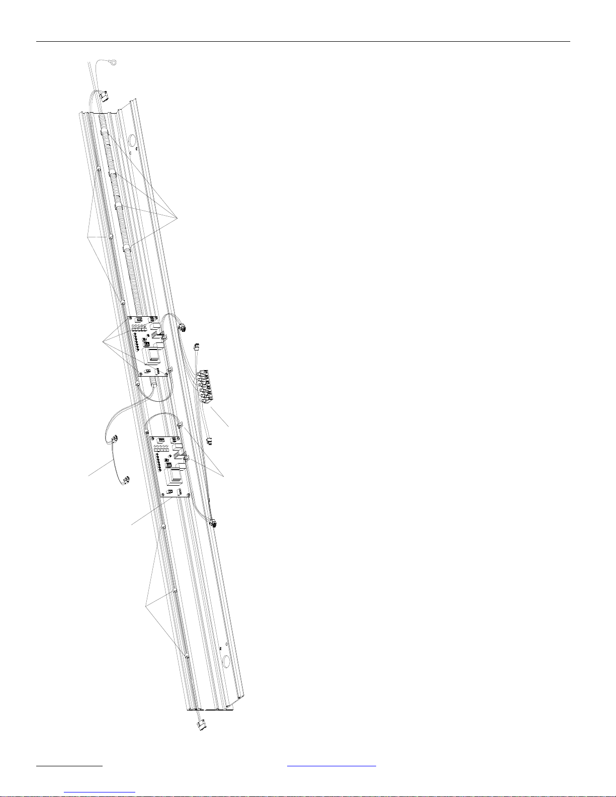
Model 710 Swing Door System
CABLE CLAMP
P/N 14-9959
WIRE HARNESS CLIP
P/N 24-1447
SCREWS & SPACERS
P/N 24-4941-16 & 14-8743
Figure 6 – Simultaneous Pair Door Conversion
of GT710
MAIN HARNESS
P/N 22-10065
WIRE SADLE
SIMULTANEOUS PAIR
POWER HARNESS
P/N 14-5883
MAGNUM IV BOARD
P/N 24-8900-04
WIRE HARNESS CLIP
P/N 24-1447
P/N 14-9960
SIMULTANEOUS PAIR DOOR CONVERSION of GT710
(SIDE BY SIDE CONTROL)
NABCO
ENTRANCES INC 877-622-2694 www.nabcoentrances.com - 11 -
DN0040
Page 12
Model 710 Swing Door System
C.W.
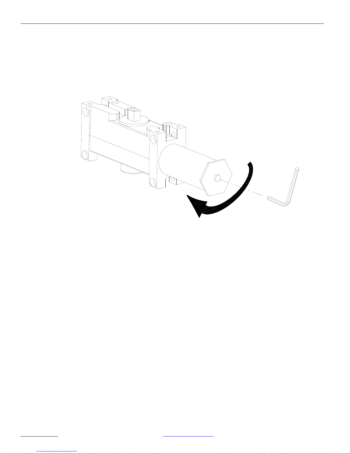
Hydraulic Closer The door closer has an adjustment for “opening force” when the doors is used in a
manual mode that is preset at the factory. The setting is based on a 30-inch
exterior door and a 38-inch interior door. Adjustments are made using an allen
wrench as shown in Figure 7. Turn the screw clockwise for larger doors and
counterclockwise for smaller doors.
DN0032
Figure 7 – Hydraulic Closer.
NABCO
ENTRANCES INC 877-622-2694 www.nabcoentrances.com - 12 -
Page 13
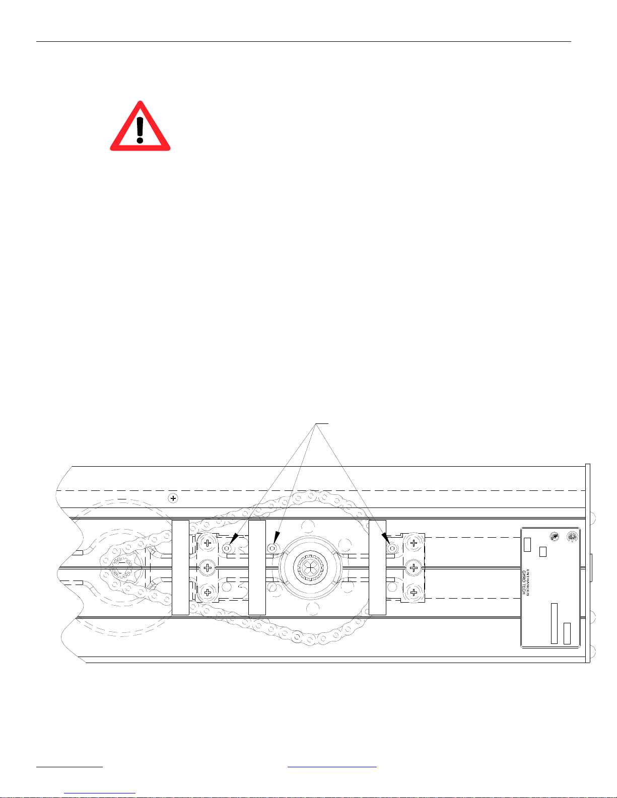
Door Closing Adjustment Procedure
The hydraulic closer must be operating properly BEFORE the Magnum control is
adjusted.
Warning: Improperly installed or adjusted closers may cause property
damage or personal injury. Please follow these instructions carefully.
Do not allow the door to slam into the frame. A “normal” closing time from a
90º open position is five to seven seconds, evenly divided between main
swing speed and latch swing speed. Use the furnished hex key to adjust
speed.
1. Remove one lead from the motor.
2. Adjust the main and latch speeds.
To slow MAIN SPEED of door, turn the main speed screw clockwise.
To slow LATCH SPEED of door, turn the latch speed screw clockwise.
Model 710 Swing Door System
3. Reconnect motor lead.
Note: It may be necessary to rotate the output shaft with the arm to align the
holes in the large sprocket with the access holes in the header.
LCN Adjustment
in
Manufactured
NABCO
S82 W 18717 Ge mini Drive
LATCH SPEED
MAIN SPEED
BACK CHECK
Muskeg o, WI 53 150 USA
LISTED
R
R
Pedestrian Commercial & Industrial
For Commercial or Industrial Use
Commande de porte pietonniere a
usage commercial ou industriel
Amps
Max
115 Volts
60 Hz
Pedestrian Door Operator
501 S
Model No.
DN0041
NABCO
ENTRANCES INC 877-622-2694 www.nabcoentrances.com - 13 -
TL
Figure 8 – Hydraulic Closer Adjustment.
Page 14
Setting Back Check and
Door Closed Switches
Model 710 Swing Door System
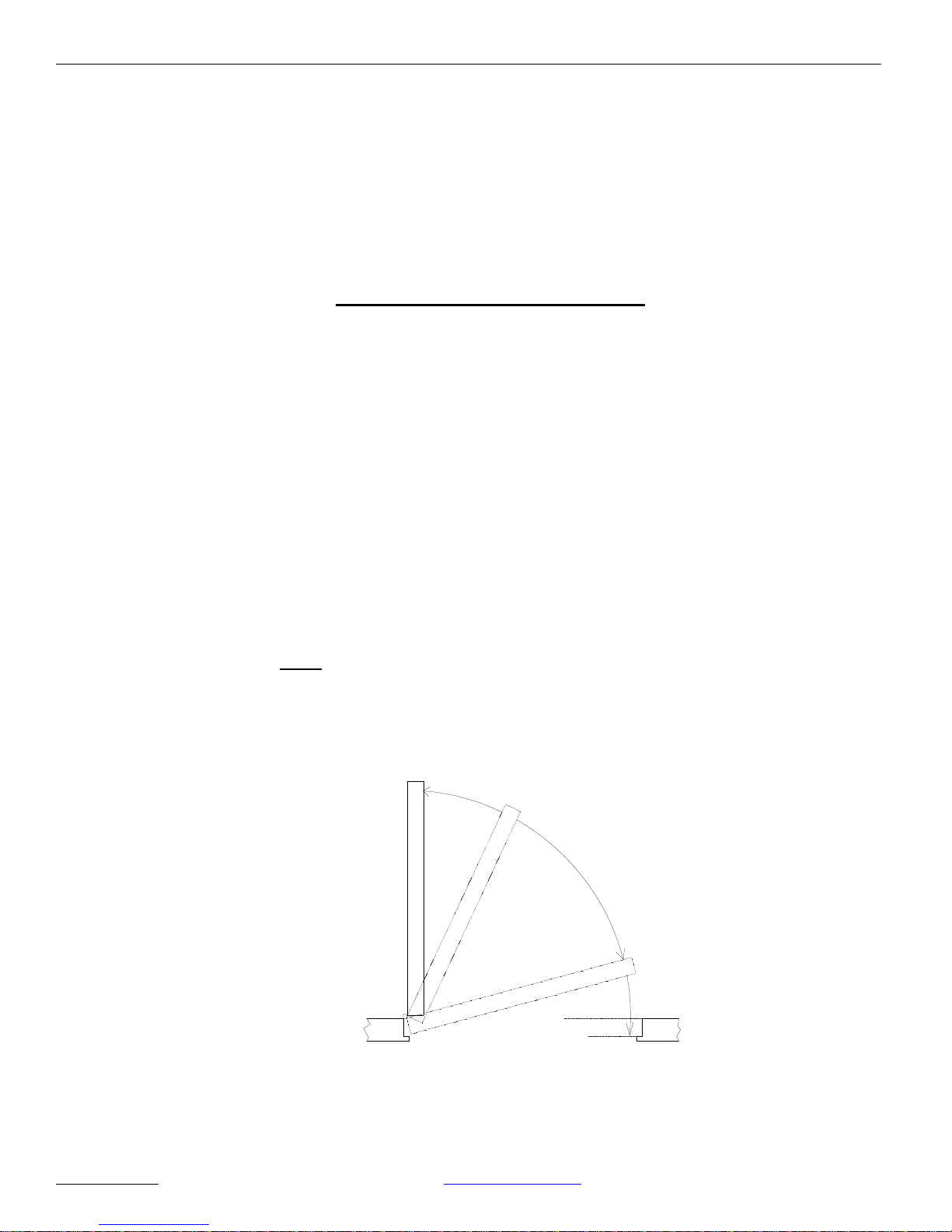
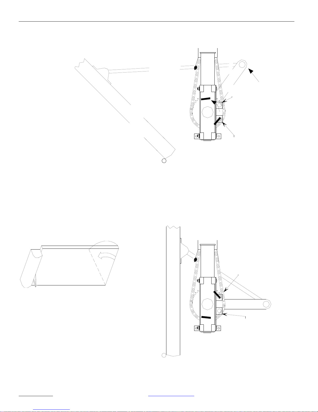
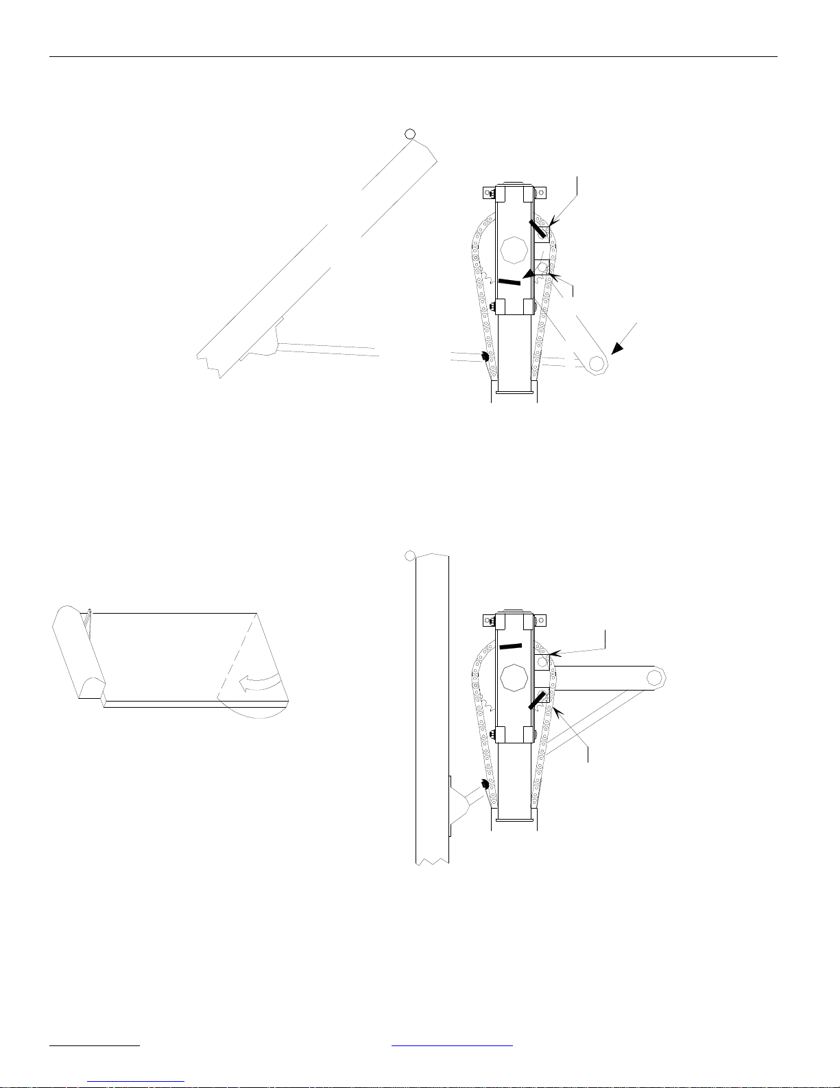
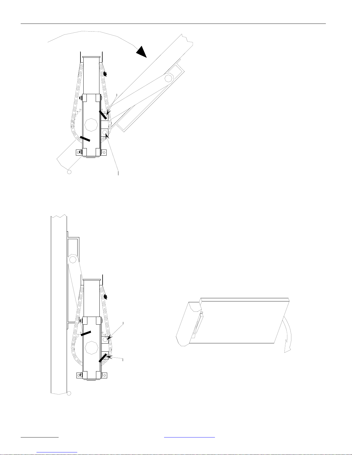
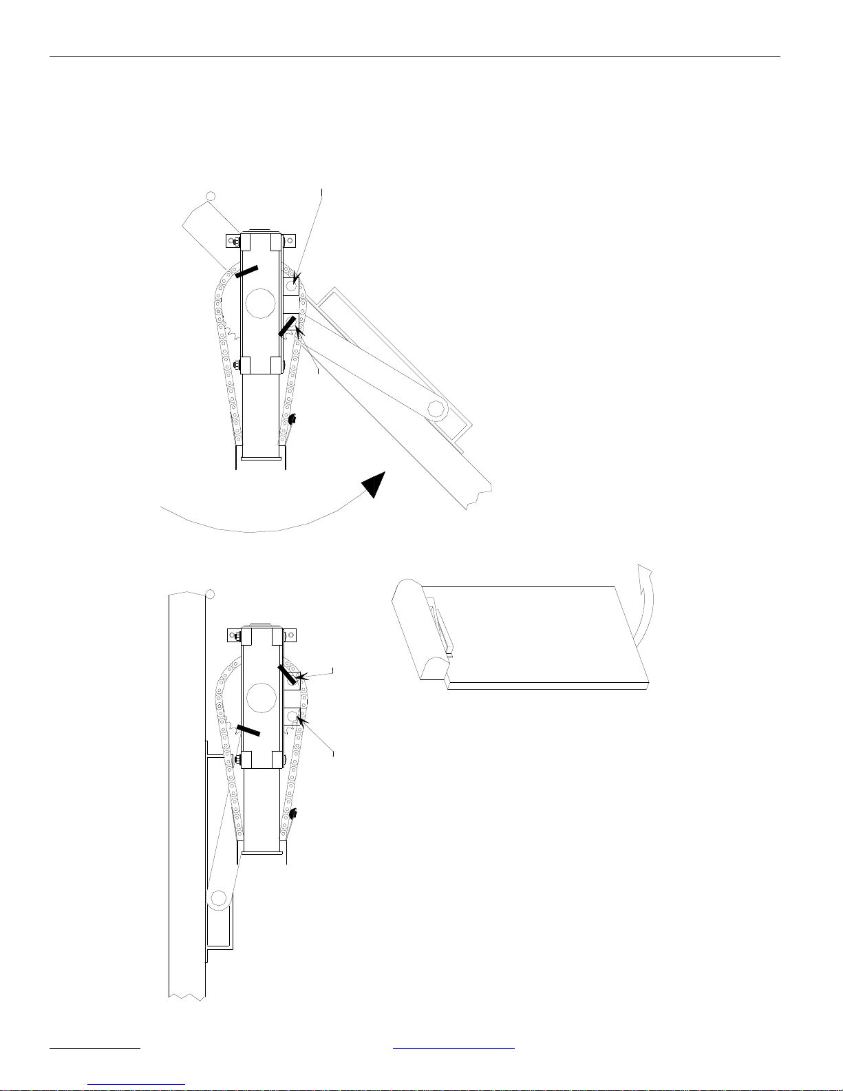
The GT 710 has two magnetic switches that control the back check location
and monitors the door closed position. The back check magnet must be installed
before the unit is tested. It signals the motor to slow down so the door does not
slam open.
The door closed magnet is optional. It is used to signal the control board that the
door is closed. It is used in applications where a sensor is on the swing side of
the door and wired into the safety with lockout circuit. The switches are closed
by magnets installed by the installer onto the main sprocket gear.
The magnets are not inside the header!
Locate the ¼-inch square and 1-inch long magnets in the parts bag. To position
the magnets, use the appropriate configuration from Figures 10 through 13.
Start with the door in the closed position. Place a magnet under the door closed
switch with the white side up. This magnet will deactivate the optional presence
detector as the door begins to open.
Move the door to the 45º position. Place a magnet under the back check switch
with the white side up. The magnet is positioned to move under the switch when
the door is opened to 45º. Use the appropriate configuration from Figures 10
through 13. This magnet will command the motor to reduce the door speed to
the setting of the back check potentiometer. Improper placement of this magnet
will cause the door to slam into the door stop.
After power is applied to the unit and the position of the magnets is “fine tuned”
to make the door functional, the magnets should be epoxied in place following the
instructions on the epoxy packaging.
Full
Open
B
a
c
k
c
h
e
c
k
M
a
i
n
s
p
e
e
d
Latch
Check
Closed
DN0035
Figure 9 – Stages of Door Travel
NABCO
ENTRANCES INC 877-622-2694 www.nabcoentrances.com - 14 -
Page 15
Model 710 Swing Door System
Door Closed Switch
DOOR OPEN 45°
in positions shown.
magnets should end up
When door is open 45°,
Back Check
Switch
Rotation
NABCO
ENTRANCES INC 877-622-2694 www.nabcoentrances.com - 15 -
Left Hand Outswing
Figure 10 – Left Hand Outswing
DOOR CLOSED
Door Closed Switch
Back Check
Switch
With door in the closed
"White Side Up"
in positions shown.
position, place magnets
DN0042
Page 16
Model 710 Swing Door System
Back Check
Switch
DOOR OPEN 45°
Rotation
in positions shown.
When door is open 45°,
magnets should end up
Right Hand Outswing
Door Closed Switch
Back Check
Switch
DOOR CLOSED
Figure 11 – Right Hand Outswing Door Shown
NABCO
ENTRANCES INC 877-622-2694 www.nabcoentrances.com - 16 -
in positions shown.
Door Closed Switch
With door in closed position,
place magnets "White Side Up"
DN0043
Page 17
Back Check
Model 710 Swing Door System
Switch
45°
DOOR AT
DOOR CLOSED
Door Closed
Back Check Switch
Switch
magnets should end
When door is at 45°,
up in positions shown.
Inswing
Right Hand
in positions shown.
With door in closed position,
place magnets "White Side Up"
NABCO
ENTRANCES INC 877-622-2694 www.nabcoentrances.com - 17 -
Door Closed
Switch
DN0044
Figure 12 – Right Hand Inswing Door Shown.
Page 18
Door Closed
Switch
Model 710 Swing Door System
magnets should end
When door is at 45°,
up in positions shown.
Back Check
Door Closed
45°
Switch
DOOR AT
Switch
DOOR CLOSED
NABCO
ENTRANCES INC 877-622-2694 www.nabcoentrances.com - 18 -
Back Check Switch
Inswing
Left Hand
place magnets
"White Side Up"
in positions shown.
Figure 13 – Left Hand Door Inswing Shown
With door in closed position,
DN0045
Page 19

Model 710 Swing Door System
Simultaneous Pair
Installations
The installer first has to configure each of the doors independently with the
speeds and timing desired. Then adjust the potentiometers on the door controller
to closely mimic those settings.
Control Switches An ON-OFF-HOLD OPEN switch assembly has been provided in the harness. It
can be mounted inside the header or where it is easily accessible to the customer.
Drill a 7/8” diameter hole in the center of the location to install the switch. Use
the switch as a template to drill (2) 11/64” diameter mounting holes. Use the two
screws provided to mount the switch. It the switch assembly is not desired,
replace it with jumper from the parts bag.
Signage After the door has been adjusted properly and tested, decals should be applied to
the door such that they are visible from either side of the door. Depending on the
type of the door activation, certain decals must be displayed. Refer to Section 6
of ANSI A156.19 Standard for Power Assist and Lower Energy Power Operated
Doors. Decals have been provided with the GT 710 to comply with all the
installation applications described in ANSI A156.19.
NABCO
ENTRANCES INC 877-622-2694 www.nabcoentrances.com - 19 -
Page 20
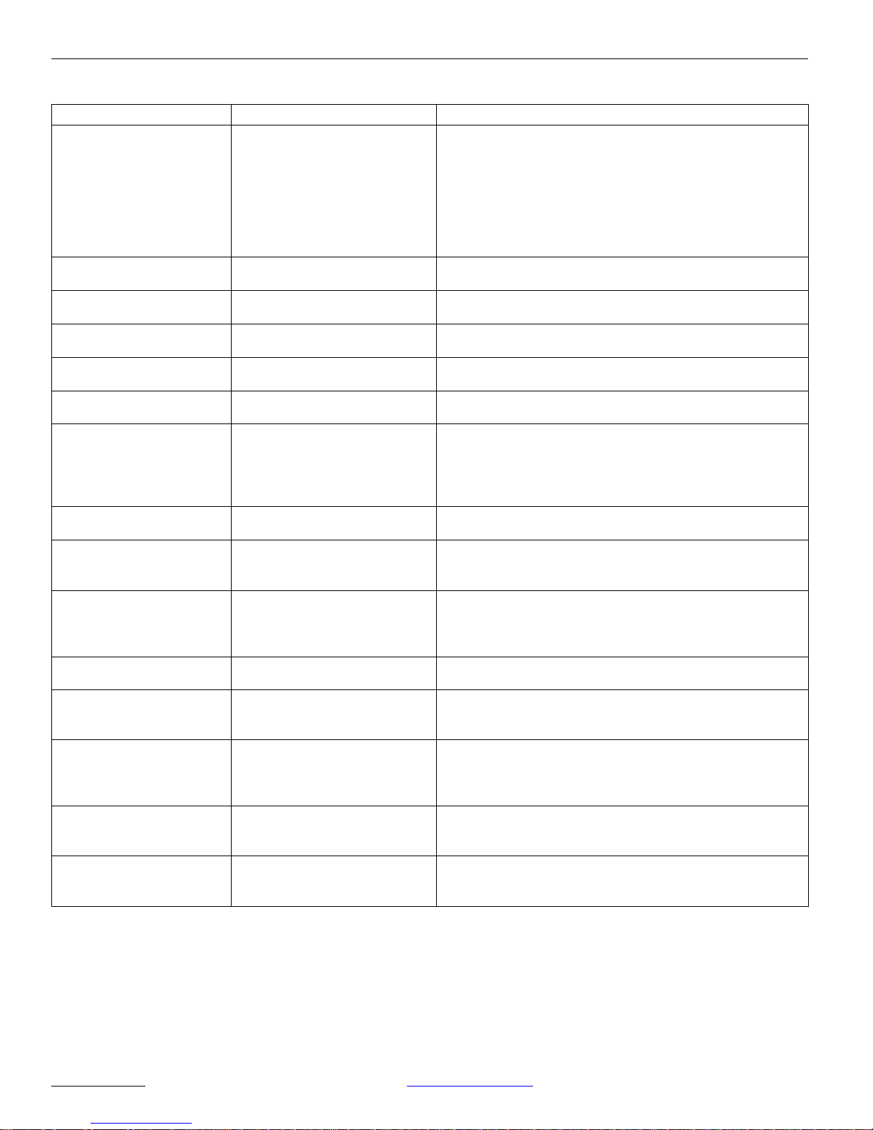
Troubleshooting
Symptom Action/Cause Solution
Operator does not function. 1. Check Fuse 2 (F2).
2. Check for 120 VAC at
connector J5.
3. Check power to
activation device at
connector J2.
4. Check Fuse 1 (F1).
Adjustment of Hydraulic
Closer hasno effect.
Door slams closed. Main speed on hydraulic closer
Door slams open. Back check speed not adjusted
Fuse 1 (F1) blows when
door open is triggered.
Door moves in wrong
direction.
Back check adjustment on
Magnum board has no
effect.
Unit leaks oil. Adjusting screws on hydraulic
No back check or motor
continues to drive after door
is closed.
Door does not stay tightly
closed.
Safety or Presence Sensor
does not function.
Safety or Presence Sensor is
activated by closing door.
Floor mat, holding beams or
other accessories do not
function while door is
moving.
Sensor shows activation
signal sent, but door does
not open.
One sensor does not activate
both doors on a
simultaneous pair.
Check 4 pin motor connector on
the board.
not adjusted properly.
or magnet not in proper location.
Check door activation device
power consumption.
Check polarity of motor input
wires at connector on motor.
The fully open door position is
greater than 90º and the back
check adjustment on the
hydraulic closer is overriding the
controls of the Magnum board.
closer have been removed.
Magnets on main sprocket not in
correct position.
1. Preload on swing arm is
not correct.
2. Building stack pressure
is excessive.
No power to sensor or defective
sensor.
Connection of sensor to wiring
harness was to “Safety” not
“Safety w/Lockout”.
Connection of accessories was
made to “Safety w/Lockout” not
“Safety”.
Sensor not connected properly to
activation connector.
Sensor is not connected to both
control boards.
1. Replace fuse.
2. Check incoming power. If power is good, check
3. If current exceeds 0.5 amps at 24 VAC, replace with
4. If blown, replace fuse.
Pin #2 and #4 must be jumped by a wire.
Turn main speed in direction of turtle.
Adjust back check potentiometer or relocate magnet.
If current draw exceeds 0.5 amps at 24 VAC, replace with
lower draw sensor.
Reverse motor leads.
Adjust the back check screw on the bottom of the header out
one turn.
Replace hydraulic closer.
Follow instructions on Page 14 to properly align magnets.
1. Position arm 45º as shown on Figures 11 through 14.
2. Upgrade operator unit to GT 500.
Check harness wiring to wire diagram on Page 21.
Rewire Safety Sensor to “Safety w/Lockout” connector.
Rewire accessory to “Safety” connection.
Check harness wiring to wiring diagram on Page 21.
Install simultaneous pair harness (P/N 2210270).
Model 710 Swing Door System
connection to motor. Replace motor if necessary.
lower draw sensor.
If F1 is OK, check power to activating devices at J2.
Voltage is too low, reduce accessory load.
NABCO
ENTRANCES INC 877-622-2694 www.nabcoentrances.com - 20 -
Page 21

Appendix A
EXCERPTS FROM ANSI/BHMA A156.19 – 1997
4.0 REQUIREMENTS FOR LOW ENERGY SWINGING POWER
OPERATED DOORS OR LOW ENERGY SWINGING POWER
OPEN DOORS
4.1 Opening Time
4.1.1 Doors shall be field adjusted so that opening time to back check or 80
degrees, which ever occurs first, shall be 3 seconds or longer as required
in Table 1. Back check shall not occur before 60 degrees opening.
4.1.2 Total opening time to fully open shall be 4 seconds or longer.
4.2 Closing Time
4.2.1 Doors shall be field adjusted to close from 90 degrees to 10 degrees in 3
seconds or longer as required in Table 1.
Model 710 Swing Door System
4.2.2 Doors shall be field adjusted to close from 10 degrees to fully closed in
not less than 1.5 seconds.
4.3 The door shall be field adjusted to remain fully open for not less than 5
seconds unless a sensing device is used to hold the door open.
4.4 The force required to prevent a stopped door from opening or closing shall
not exceed a 15 lbf (67 N) applied 1 in (25 mm) from the latch edge of the
door at any point in the opening or closing cycle.
4.5 The kinetic energy of a door in motion shall not exceed 1.25 lbf-ft (1.69
Nm). Table 1 provides speed settings for various widths and weights of
doors for obtaining results complying with this paragraph.
4.6 In the event of power failure to the operator, doors shall open with a
manual force not to exceed a 15 lbf (67 N) or torque of 40 lbf-in (4.5 Nm)
to release a latch, a 30 lbf (133 N) to set the door in motion, and a 15 lbf
(67 N) to fully open the door. The forces shall be applied at 1” (25 mm)
from the latch edge of the door.
NABCO
ENTRANCES INC 877-622-2694 www.nabcoentrances.com - 21 -
Page 22
Model 710 Swing Door System
Nm
2260
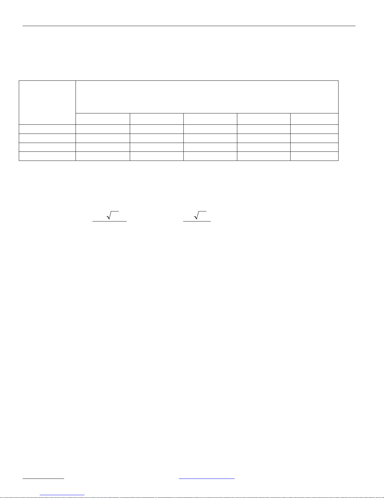
Table 1
Minimum Opening Time to Back Check or 80 degrees, which ever occurs first, or Minimum Closing time
from 90 degrees to Latch Check or 10 degrees. Back check shall not occur before 60 degree opening.
“D” = Door
“W” = Door Weight in Pounds (kg)
Leaf Width in
Inches (mm)
100 (45.4) 125 (56.7) 150 (68.0) 175 (79.4) 200 (90.7)
30 (762) 3.0* 3.0 3.0 3.0 3.5
36 (914) 3.0 3.5 3.5 4.0 4.0
42 (1067) 3.5 4.0 4.0 4.5 4.5
48 (1219) 4.0 4.5 4.5 5.0 5.5
Matrix values are in seconds.
Doors of weights and widths can be calculated using the formula:
133
WD
ftlbf
T
T
WD
WHERE: T = Time, seconds
D = Door width, inches (mm)
W = Door weight, lbs (kg)
The values for “T” time have been rounded up to the nearest half second. These values are based on
kinetic energy of 1.25 lbf-ft.
The value for the 30 inch wide, 100 pound door actually calculates to 2.5 seconds with rounding. 3.0
seconds was used as a more conservative value.
NABCO
ENTRANCES INC 877-622-2694 www.nabcoentrances.com - 22 -
 Loading...