

Page 1
User Manual
NE Series (20-30kVA)
Page 2

Page 3

i
All rights reserved ©N1 Critical Technologies, Inc.
Copyright © N1 Critical Technologies 2018. All rights reserved.
N1 Critical Technologies
Janesville, WI 53545
No part of this document may be reproduced or transmitted in any form or by any means without prior
written consent of N1 Critical Technologies, Inc.
Trademarks and Permissions
and other N1 Critical Technologies marks are trademarks of N1 Critical Technologies.
All other trademarks and trade names mentioned in this document are the property of their respective holders.
Notice
The purchased products, services and features are stipulated by the contract made between N1 Critical
technologies and the customer. All or part of the products .services and features described in this document
may not be within the purchase scope or the usage scope. Unless otherwise specification in the contract, all
statements, information, and recommendations in this document are provided “AS IS” without warranties,
guarantees or representations of any kind, either express or implied.
The information in this document is subject to change without notice. Every effort has been made in the
preparation of this document to ensure accuracy of the contents, but all statements, information, and
recommendations in this document do not constitute a warranty of any kind, express or implied.
Address: 211 N. Parker Drive
Manufacturer: N1 CRITICAL TECHNOLOGIES.
Website: https://n1critical.com
E-mail: [email protected]
Customer Service: 877-226-3311
Page 4
ii
All rights reserved ©N1 Critical Technologies, Inc.
NE Series (20-30kVA)
User Manual
Foreword
Summaries
Thank you for choosing the NE Series (20-30kVA) product.
This document gives a description of the NE Series (20-30kVA) product, including the UPS features,
performance, appearance, structure, working principles, installation, operation and maintenance. etc.
Please save the information after reading, in order to consult in the future.
Symbol Conventions
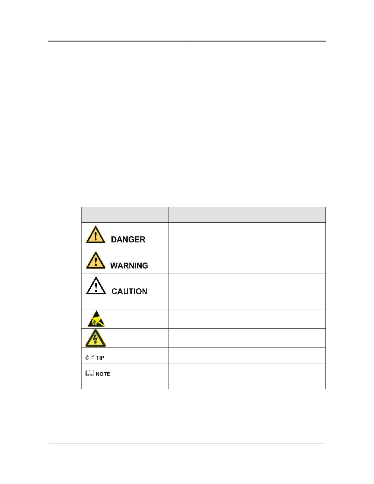
The manual quotes the safety symbols, these symbols used to prompt users to comply with safety
matters during installation, operation and maintenance. Safety symbol meaning as follows.
Symbol Description
Foreword
Alerts you to a high risk hazard that could, if not avoided,
result in serious injury or death.
Product standard: Q/ZZKJ001
Alerts you to a medium or low risk hazard that could, if not
avoided, result in moderate or minor injury.
Alerts you to a potentially hazardous situation that could, if
not avoided, result in equipment damage, data loss,
performance deterioration, or unanticipated results.
Anti-static prompting.
Be care electric shock prompting.
Provides a tip that may help you solve a problem or save time.
Provides additional information to emphasize or supplement
important points in the main text.
Page 5

NE Series (20-30kVA)
User Manual
Foreword
iii
All rights reserved ©N1 Critical Technologies, Inc.
Change History
Changes between document issues are cumulative. The latest document issue contains all the changes
made in earlier issues.
Issue 001 (2018-04-08)
Page 6

iv
All rights reserved ©N1 Critical Technologies, Inc.
NE Series (20-30kVA)
User Manual
Contents
Contents
Chapter 1 Safety Description...................................................................................................................1
1.1 Safety Announcements ..............................................................................................................................................1
Chapter 2 Overview..................................................................................................................................5
2.1 Model Meaning..........................................................................................................................................................5
2.2 Product Intro ..............................................................................................................................................................5
2.2.1 Features.............................................................................................................................................................6
2.3 Work Principle...........................................................................................................................................................7
2.3.1 Work Principle Block Diagram ........................................................................................................................7
2.3.2 Work Mode.......................................................................................................................................................8
2.3.3 Work Principle for Series Hot Standby ............................................................................................................9
Appearance and Panel.............................................................................................................................................10
2.4
2.4.1 Appearance .....................................................................................................................................................10
2.4.2 Panel ...............................................................................................................................................................10
Chapter 3 Installation.............................................................................................................................13
3.1 Unpacking and Checking.........................................................................................................................................13
3.2 Environment.............................................................................................................................................................13
3.3 Tools14
3.4 Installation Clearance ..............................................................................................................................................16
3.5 Selection of Input and Output Cables ......................................................................................................................16
3.6 Surge Protection.......................................................................................................................................................17
3.7 Installation of the UPS.............................................................................................................................................18
3.7.1 Installation of NE Series (20-30kVA) UPS....................................................................................................18
3.8 Electrical Connection...............................................................................................................................................20
3.8.1 Wiring for Single-unit (NE##L & NE##PL models) ...................................................................................20
3.8.2 Wiring for Series System (NE##PL models ONLY) .....................................................................................21
Page 7

v
All rights reserved ©N1 Critical Technologies, Inc.
NE Series (20-30kVA)
User Manual
Contents
3.8.3 Wiring for Parallel System (NE##PL Models ONLY) ..................................................................................22
3.9 Connect Communication Wires...............................................................................................................................23
3.9.1 RS232 Communication ..................................................................................................................................23
3.9.2 RS485 Communication ..................................................................................................................................24
3.9.3 Dry Contact Communication..........................................................................................................................24
3.9.4 SNMP Card (optional)....................................................................................................................................25
3.9.5 Battery Switch ................................................................................................................................................25
3.9.6 Anti-reverse Feedback Contactor (Included on “P”-Models) ........................................................................25
Chapter 4 Operation Guide ...................................................................................................................27
4.1 Check before Startup ...............................................................................................................................................27
4.1.1 Check the Electrical Connection ....................................................................................................................27
4.1.2 UPS Testing....................................................................................................................................................28
4.2 Precautions for Operating UPS................................................................................................................................28
4.3 Operation .................................................................................................................................................................29
4.3.1 Check Before Power-on .................................................................................................................................29
4.3.2 Start the UPS ..................................................................................................................................................30
4.3.3 Start Load .......................................................................................................................................................30
4.3.4 Shutdown UPS................................................................................................................................................30
4.4 Operation for Manual Maintenance.........................................................................................................................31
4.5 Operation for Parallel System (P-Models Only)......................................................................................................32
4.5.1 Start Parallel System.......................................................................................................................................32
4.5.2 Shut Down Parallel System ............................................................................................................................34
4.5.3 Exit Parallel System Online............................................................................................................................34
4.5.4 Enter a UPS Online ........................................................................................................................................35
4.5.5 Redundancy Function of the Parallel System.................................................................................................35
4.6 Operation of Touch Screen ......................................................................................................................................35
4.6.1 Menu Structure of Touch Screen....................................................................................................................35
4.6.2 Main Page.......................................................................................................................................................36
4.6.3 Work Status of the System .............................................................................................................................37
4.6.4 Controlling Function ......................................................................................................................................43
4.6.5 Monitoring Function.......................................................................................................................................46
Page 8

vi
All rights reserved ©N1 Critical Technologies, Inc.
NE Series (20-30kVA)
User Manual
Contents
4.6.6 Parameters Setting ..........................................................................................................................................49
4.6.7 Information Inquiry ........................................................................................................................................62
Chapter 5 Maintenance Guide...............................................................................................................67
5.1 Safety Precaution .....................................................................................................................................................67
5.2 Periodic Preventative Maintenance .........................................................................................................................67
5.3 Battery Maintenance ................................................................................................................................................68
5.3.1 Precaution for Battery Charging.....................................................................................................................68
5.3.2 Battery Maintenance.......................................................................................................................................68
5.3.3 Battery Replacement ......................................................................................................................................68
5.4 Fan Maintenance......................................................................................................................................................69
Chapter 6 Troubleshooting ....................................................................................................................70
6.1 Judge the UPS Status ...............................................................................................................................................70
6.2 Deal with Common Faults .......................................................................................................................................71
6.3 Emergency Troubleshooting....................................................................................................................................74
6.4 Replace the Fuse ......................................................................................................................................................75
A Technical Specifications .....................................................................................................................76
B Acronyms and Abbreviations.............................................................................................................79
Page 9

NE Series (20-30kVA)
User Manual
Chapter 1 Safety Description
1
All rights reserved ©N1 Critical Technologies, Inc.
Chapter 1 Safety Description
1.
2.
3.
This chapter describes the safety symbols and safety announcements. Please read this user manual
carefully prior to installing the device. It provides important information on safe and efficient
installation.
1.1 Safety Announcements
The UPS contains high temperature and high voltage, which can be extremely dangerous. Please
comply with the relevant safety standards and operational procedures during installation, operation and
maintenance, or it may result in death, personal injury or equipment damage. The safety precautions
mentioned in the user manual are only a supplement to local safety regulations. The manufacturer does
not assume responsibility for any breach or violation of general requirements.
The charging voltage requirements of different brands and different types of batteries may vary. Make
sure that the charging voltage of UPS and battery match. If any doubt exists, please consult the
manufacturer for support. Any change of system configuration, structure or components will affect the
performance of UPS. If the user wants to make any changes, please consult with the manufacturer in
advance.
Only authorized professionals are allowed to open the UPS chassis. The input and output voltage
of the UPS is high and dangerous. Contacting high voltage can lead to injury or death.
Please disconnect the AC power and battery to isolate power input before maintenance. Test the
output terminal block with a voltmeter before maintenance to ensure that the input power is turned
off and in a safe condition.
Even if all external power are disconnected, there still exists residual electric charge inside the
UPS, and the output terminal blocks still exists high voltage which may endanger personal life.
Technicians should wait enough time (≥ 10 min) before opening the UPS chassis an ensure all
charge is released.
Page 10
NE Series (20-30kVA)
User Manual
Chapter 1 Safety Description
2
All rights reserved ©N1 Critical Technologies, Inc.
4.
5.
6.
7.
8.
9.
10.
Life risk!
Cannot connect with unbalanced load, half-wave rectification load or inductive load!
Drilling holes on the cabinet is prohibited!
Battery cables are not isolated from AC input. Dangerous voltage may exist between battery
terminal and ground terminal. The battery contains high voltages that may cause injury or death.
Please make sure they are insulated when installing or using the UPS.
Conductive objects such as watches, bracelets and rings should not be worn during operation and
maintenance.
The UPS installation should be done only by people who have the qualification of high voltage and
AC power operation. Maintenance and repair for power systems must only be done by
professionally trained technicians.
Leakage risk! The UPS must be grounded before electrical connection. The ground terminal must
be connected to the ground.
It is prohibited to short circuit the positive and negative poles of the battery. The connection of
battery must be tight. It is prohibited to touch the battery’ s two wire connectors or bare wire
terminals, or it may damage the battery and/or endanger life.
Prevent the battery electrolyte from overflowing. The metal objects and circuit board inside the
UPS will be corroded by the electrolyte, which will result in equipment damage and short circuiting.
Battery should be kept away from fire and all other electrical equipment that could cause sparks,
heat or flame. Avoid danger or unnecessary damage to equipment and personnel.
Contacting high voltage or mains directly onto or near wet objects will cause life risk.
The output of UPS cannot connect with unbalanced load, half-wave rectification load or inductive
load, such as air-conditioner, hair dryer, starter, electric drill, motor, daylight lamp, etc.
Inappropriate drilling will damage the device inside the cabinet. Metal debris generated by drilling
enters the cabinet will lead to PCB (circuit board) short circuiting.
Page 11
NE Series (20-30kVA)
User Manual
Chapter 1 Safety Description
3
All rights reserved ©N1 Critical Technologies, Inc.
It is dangerous to operate during lightning storm!
Operation under high voltage and AC operation is prohibited during a lightning storm. During a
Be careful of static!
Installing and removing power cables with AC input are dangerous!
Do not connect the ground wire and neutral wire, live wire and neutral wire
Please use specified battery model!
Battery connection must be done according to instructions!
lightning storm, the atmosphere produces a strong electromagnetic field. In order to avoid equipment
from being damaged lightning, the equipment should be grounded appropriately.
To prevent static damaging sensitive components, make sure that you are wearing an anti-static wrist
strap before contacting sensitive components (such as the flapper, circuit boards, IC chips, etc.).
Ensure the clip end of the wrist strap is well grounded.
Installing and removing power cables with AC input are prohibited. Please turn off mains switch
before connecting or removing power cables. Before connecting the cable, make sure the cable
connected, cable labels are matched with the actual installation.
reversely, which will cause short circuit.
The UPS should be well grounded, the voltage between ground line and neutral line should be less than 5V.
Non-specified battery will cause damage to UPS.
Battery connection must be done according to the user manual. Non-standard operation will damage
the battery, even endanger life.
Page 12
NE Series (20-30kVA)
User Manual
Chapter 1 Safety Description
4
All rights reserved ©N1 Critical Technologies, Inc.
Be careful for the rotating fan!
When remove the fan, do not put fingers or tools into the rotating fans before the fan stops in order
Keep good ventilation of the equipment!
The product is class C3 and grade A equipment.
Warning label should be affixed outside UPS position area.
to avoid equipment damage or injury.
Ensure that no objects are in front of air-in and air-out holes and fans, to keep good ventilation.
When used in a residential building, additional measures should be took to prevent tampering.
When UPS is disconnected, it still contains dangerous voltage, the warning labels should include
1. This line is for UPS power supply. 2. Please disconnect this line before line operation.
Page 13

5
All rights reserved ©N1 Critical Technologies, Inc.
NE Series (20-30kVA)
User Manual
Chapter 2 Overview
Chapter 2 Overview
N1C.NE##L & N1C.NE##PL
“N1C.” is the Manufacturer of the UPS (N1 Critical Technologies)
“NE” is the series name of the company’s three-phase UPS system.
The two-digit number is the maximum output power of the unit (20kVA or 30kVA).
“P” means the UPS can
be connected in parallel system. (If there is no “P” in the model number,
the unit is NOT able to be connected in parallel).
“ L” means the UPS contains an internal, long-lasting Lithium-Ion battery (lithium-iron-
phosphate chemistry).
This chapter mainly introduces the model meaning, product features, working principle, appearance,
LCD panel, etc. of the product.
2.1 Model Meaning
2.2 Product Intro
NE Series (20-30kVA) products are a high-performance UPS with a pure sine-wave and online double-
conversion performance. They are perfect for network closets, server rooms, small electronic
equipment, precise instruments, etc. They are used in finance, communication, insurance,
transportation, tax affairs, military, security, energy, education, government, enterprise, etc. They are
especially suitable for poor power-grid environments.
Page 14

6
All rights reserved ©N1 Critical Technologies, Inc.
NE Series (20-30kVA)
User Manual
Chapter 2 Overview
2.2.1 Features
The main features of NE Series (20-30kVA) UPS are as follows.
Energy conservation and high efficiency
Adopt advanced IGBT technique, which make the input power factor of UPS more than 0.99, and
greatly improve the electric energy use ratio, alleviate the load on power grid, save costs.
Digitized DSP control
The UPS uses a digital signal processor (DSP) for quickly and precisely controlling contravariance,
synchronizing phases, input power factor correction (PFC) and logics.
Intellectual fans speed regulation control
Fans adjust rotating speed in accordance with the load status to prolong the using life of fans and
decrease working noise of the machine.
ECO energy conservation mode design
The UPS has an ECO energy conservation mode. In this mode, bypass output is prior and the efficiency
of UPS is up to 97%; when the voltage or frequency deviation of bypass is excessive, UPS switches to
the inverter output mode. It not only ensures a reliable power supply for users but also saves energy.
Manual bypass maintenance design
Design bypass maintenance channel to assure the maintenance on machine without load power break.
High EMC performance
The NE Series UPS has passed professional tests on electromagnetic compatibility (EMC), including
conducting disturbance, radioactive disturbance, conducting anti-disturbance, radioactive anti-
disturbance, power falling, mass impulse, static discharging, surge, etc. The predominant EMC
characteristics can not only completely filter all kinds of disturbances on the power grid but also
efficiently reduce and eliminate the disturbance produced by the UPS itself. The UPS can be applied
to high frequency communication, broadcasting audio and video systems.
Page 15

7
All rights reserved ©N1 Critical Technologies, Inc.
NE Series (20-30kVA)
User Manual
Chapter 2 Overview
Perfect protection function
NE##PL models adopt a no-master-slave equalizing current controlling technology to realize the N+1
redundancy in parallel. Digitization equalizing current control makes the system possess strong self-
adaption capacity, higher reliability and redundancy degree, and convenient installation and debugging.
It can freely enter or exit the parallel system, which achieves the online hot maintenance of parallel
system.
LCD menu
The large liquid crystal display (LCD) shows operational status and parameters in real time; The CPU
in the machine records historical data and alerting information of the device. The LCD allows you to
switch the display language between Chinese and English.
2.3 Work Principle
2.3.1
Work Principle Block Diagram
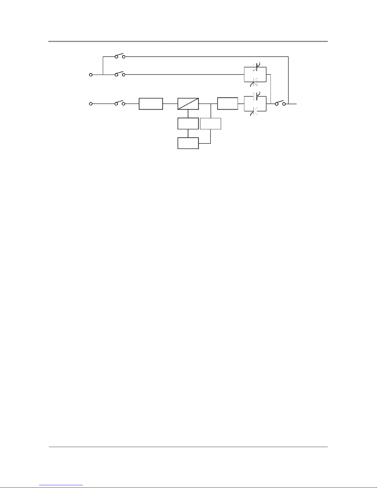
The basic work principle block diagram of NE Series (20-30kVA) is as shown in Figure2-2.
Page 16
8
All rights reserved ©N1 Critical Technologies, Inc.
NE Series (20-30kVA)
User Manual
Chapter 2 Overview
AC
Maintenance
Bypass
input
Mains SCR
PFC
DC/DC
DC/AC
Load
Mains
Battery
Battery
input
switch
Figure2-2 The basic work principle block diagram of NE Series (20-30kVA)
2.3.2 Work Mode
NE Series (20-30kVA) UPS has 4 work modes: mains mode, battery mode, bypass mode, and
maintenance bypass mode.
Mains mode
When mains are normal, the rectifier converts AC power to DC power, and then charges the battery. It
also supplies power for load.
Battery Mode
When mains are abnormal, the rectifier will automatically turn to battery input and supply power to
inverter after battery boosting so as to protect output loads from AC power interruptions.
SCR
Charger
Bypass Mode
When the inverter is abnormal (such as over-temperature, short circuit, output voltage abnormal,
overload and surpasses the power range that the inverter can withstand), the inverter will shut down
automatically to prevent damage. If the mains are still normal at this moment, the static switch will
turn to bypass to supply AC power directly to the load.
Maintenances Bypass Mode
When UPS needs to be maintained or change the battery, and the power must not be interrupted at the
same time, users can first shut down the inverter switch, and then turn on the maintenance bypass
switch, then turn off the battery, mains and bypass switches. Under the mode, AC power goes through
maintenance bypass switch to supply power to load. At this time, there is no electricity inside the UPS
(except N), and the maintainer can perform the maintenance safely.
Page 17
9
All rights reserved ©N1 Critical Technologies, Inc.
NE Series (20-30kVA)
User Manual
Chapter 2 Overview
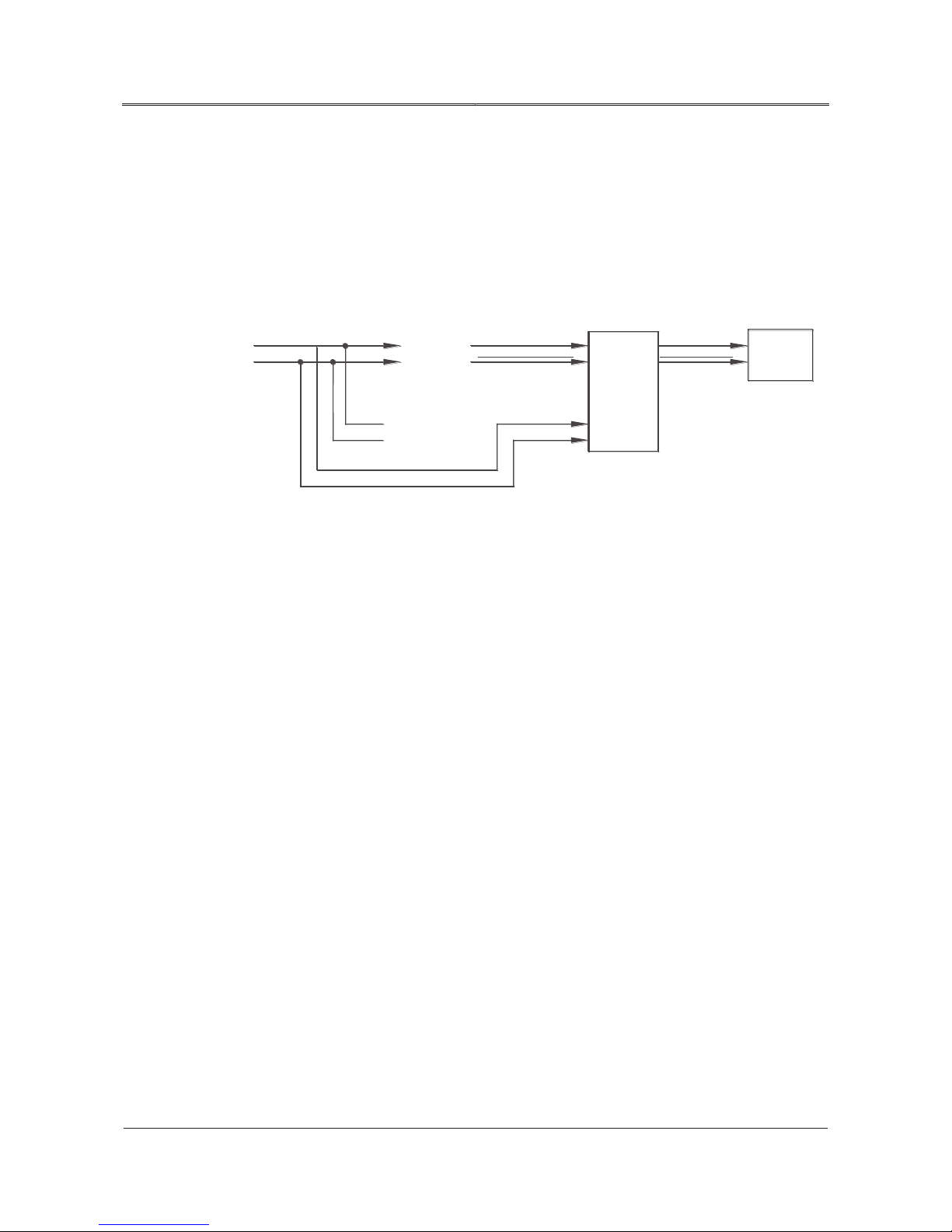
2.3.3 Work Principle for Series Hot Standby
Li
Output
Ni
Lo
No
Main UPS
Standby UPS
Connect the bypass input of UPS 1 to the output of UPS 2, it constitutes series hot standby working
mode.
If UPS 1 faults, it will switch to bypass mode automatically. At this moment, the output of UPS 2
sustains the load which is still in UPS inverting protection status, so as to ensure the safe operation of
device. If UPS 1 stays in bypass mode and UPS 2 faults, then the mains will sustain the load.
Mains
Bypass input
Main input
Figure2-3 Work principle block diagram for series hot standby
Bypass input
Main input
Load
Page 18
10
All rights reserved ©N1 Critical Technologies, Inc.
NE Series (20-30kVA)
User Manual
Chapter 2 Overview
2.4 Appearance and Panel
2.4.1
Appearance
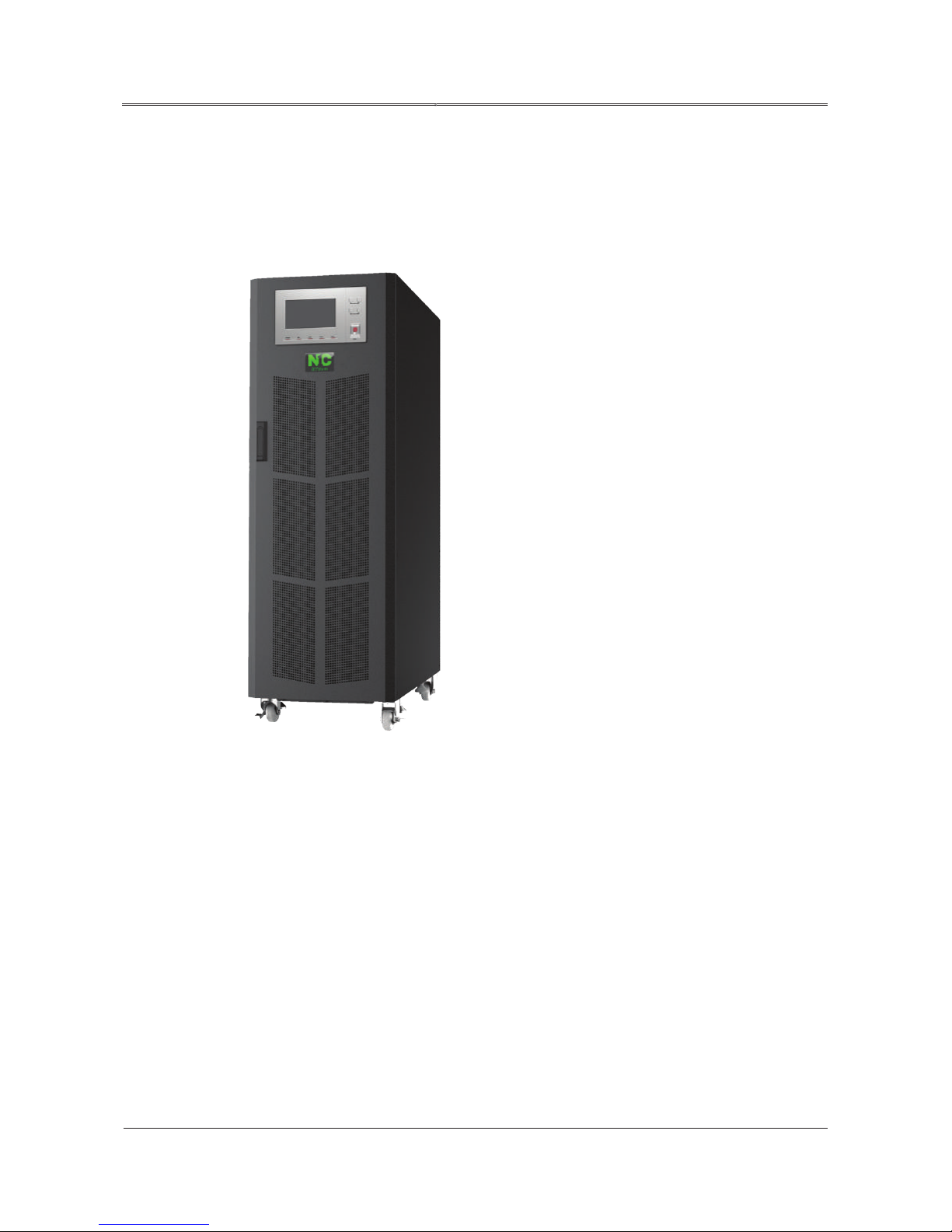
The appearance of NE Series (20-30kVA) UPS is shown in Figure2-4.
Figure2-4 Appearance of NE Series (20-30kVA) UPS
2.4.2 Panel
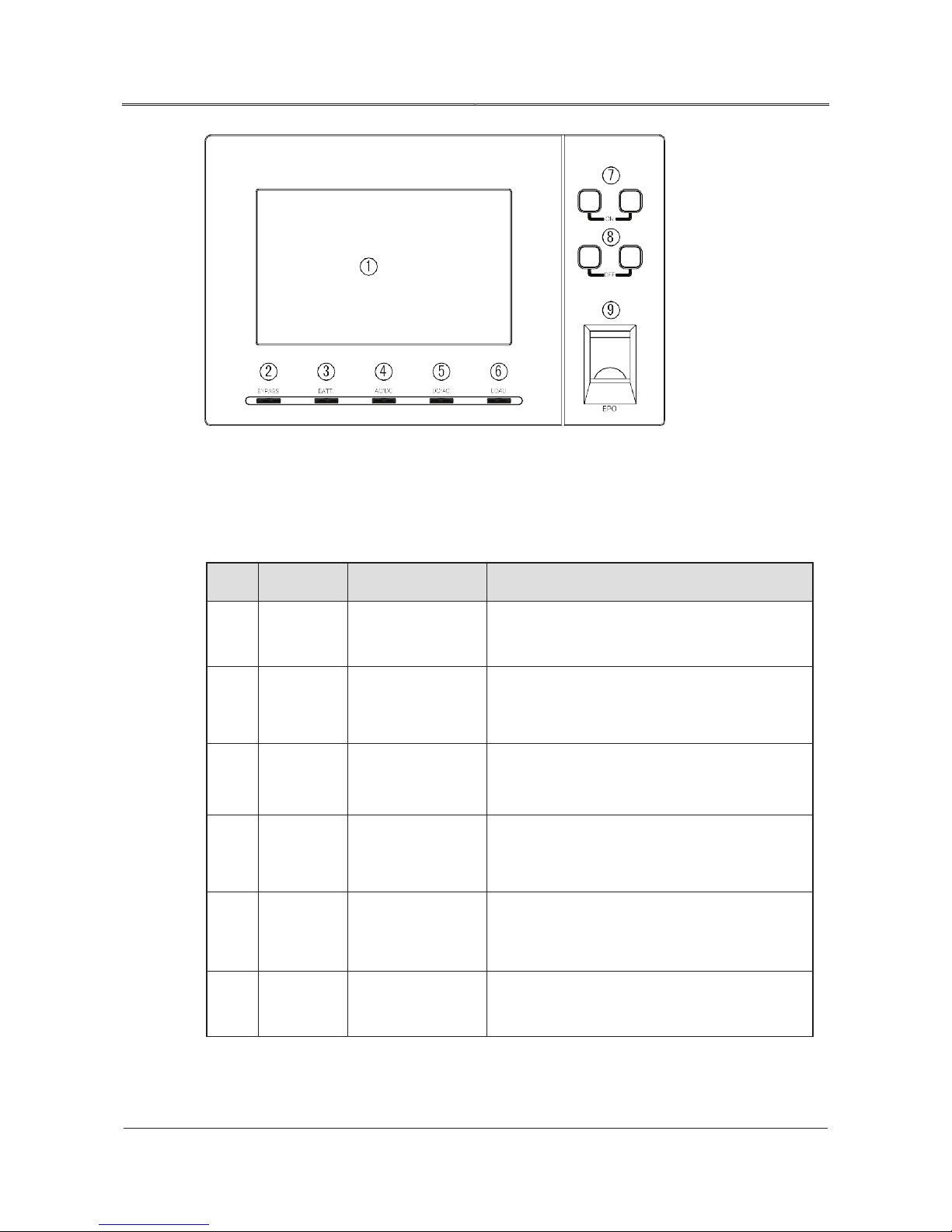
The operation panel interface of NE Series (20-30kVA) UPS is as shown in Figure2-5.
Page 19
11
All rights reserved ©N1 Critical Technologies, Inc.
NE Series (20-30kVA)
User Manual
Chapter 2 Overview
Figure2-5 Operation interface of NE Series (20-30kVA) UPS
-
The description for the operation interface of NE Series (20-30kVA) UPS is as shown in Table2-1.
Table2-1 Definition of operation interface
No. Silk-screen Name Description
1
Touch screen
Display the UPS parameters and status (such as
voltage, current, load, etc.)
Green: Bypass output
2
BYPASS Bypass indicator
Red: Bypass abnormal
Light off: Bypass normal but with no output
3
BATT.
Battery low-voltage
alarm indicator
Red: Battery abnormal alarm (it will flicker if
battery low-voltage alarm)
Green: Battery voltage normal
Green: Rectifier works normally
4
AC/DC Rectifier indicator
Red: Rectifier fault and protected
Light off: Rectifier is not working.
Green: Inverter works normally.
5
DC/AC
Inverter indicator
Red: Inverter fault and protected.
Light off: Inverter is with no output.
6
LOAD
Load alarm
indicator
Red: output abnormal
Green: Output normal
Page 20

12
All rights reserved ©N1 Critical Technologies, Inc.
NE Series (20-30kVA)
User Manual
Chapter 2 Overview
7
ON
System On
Press the two buttons simultaneously.
combination button
8
OFF
System Off
Press the two buttons simultaneously.
combination button
9
EPO EPO button
In emergency, press the EPO button. The UPS
shuts down without output
.
Page 21

13
All rights reserved ©N1 Critical Technologies, Inc.
NE Series (20-30kVA)
User Manual
Chapter 3 Installation
Chapter 3 Installation
This chapter mainly introduces the installation of the product, including unpacking and checking,
installation environment, tools, selection of input & output cables, installation procedure, installation
preparations, mechanical installation, battery cabinet installation, etc. Before installing, please pay
attention to the safety standards in the installation illustration.
3.1 Unpacking and Checking
Unpack the UPS and conduct the following items:
Inspect the UPS appearance for shipping damage. If any shipping damage is found, report it to the
carrier and your local dealer immediately. Please provide photos of the UPS damage to us, and
we will offer corresponding service.
Check the delivery list to see if the order is complete and correct. If there is any discrepancy,
take notes and contact the distributor immediately.
3.2 Environment
The UPS installation environment should meet the following requirements:
The temperature and humidity are within the range of 0–40°C and 0% –95% respectively.
It is strictly prohibited to install UPS in a working environment where there is metal conductive
dust.
Don’t install UPS outdoors.
Install the UPS in an environment with good ventilation and free of dust, volatile gas, salt, and
corrosive materials. Keep the UPS far away from water, heat source, flammable and explosive
substances. Avoid direct sunlight.
Page 22
14
All rights reserved ©N1 Critical Technologies, Inc.
NE Series (20-30kVA)
User Manual
Chapter 3 Installation
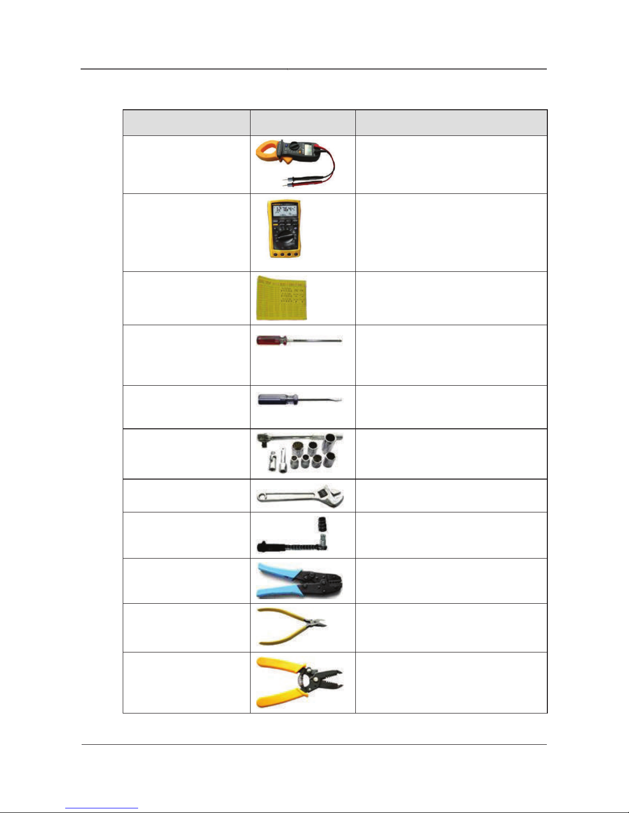
3.3 Tools
connection, and measure electronic
Tool Appearance Description
Clamp-on ammeter
Multimeter
Label paper
Phillips screwdriver (2 mm
x 150 mm and 3 mm x 250
mm)
Slotted screwdriver(2mm×
80mm)
Socket wrench
Test current
Used to check cabinet insulation and cable
performance specifications of a device, such
as voltage, current, and resistance.
Used to prepare labels.
Used to tighten screws and bolts.
Connect cable, fasten screw
Used to tighten bolts and nuts.
Adjustable spanner
Torque wrench
COAX crimping tool
Diagonal pliers
Wire stripper
Fasten bolt
Fasten bolt
Used to crimp cord end terminals.
Used to cut insulation cables and cable ties.
Used to remove the insulation layer and
jacket from a communication cable with a
small cross-sectional area.
Page 23
15
All rights reserved ©N1 Critical Technologies, Inc.
NE Series (20-30kVA)
User Manual
Chapter 3 Installation
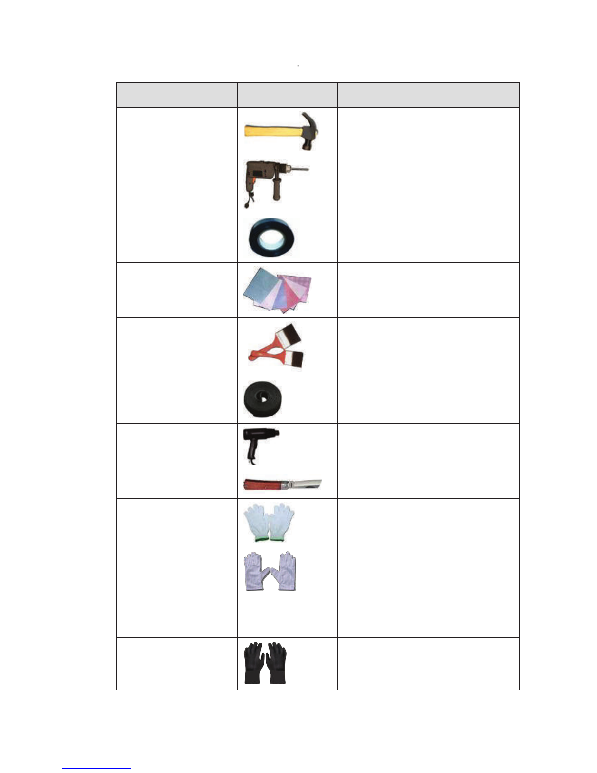
Tool Appearance Description
(ESD) from damaging a board or other
Claw hammer
Impact drill, drill
PVC insulation tape
Cotton cloth
Brush
Heat shrink tubing (Φ14 、
Beat, install, and disassemble component.
Drilling
Used to insulate wires and conductors.
Used to clean panels and shells.
Clean the panel and shell.
Used to insulate wires and conductors.
Φ18、Φ20、Φ25)
Heat gun
Electrician's knife
Protective gloves
ESD gloves
Insulated gloves
Used to heat a heat shrink tubing.
Used to strip cables.
Used to protect hands and the device on
which you operate.
Used to prevent the electrostatic discharge
electrostatic sensitive devices (ESSDs) when
you insert or remove a board or hold
an ESSD.
Used to insulate hands.
Page 24
16
All rights reserved ©N1 Critical Technologies, Inc.
NE Series (20-30kVA)
User Manual
Chapter 3 Installation
Tool Appearance Description
Hydraulic pliers
Cable tie
3.4 Installation Clearance
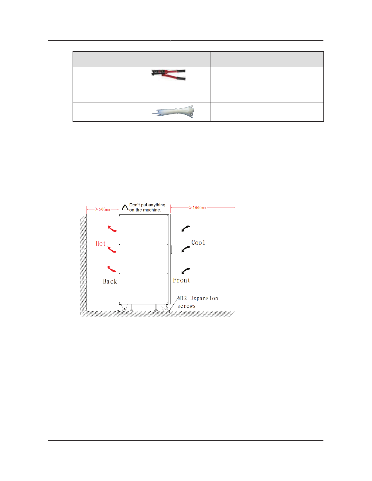
The UPS installation clearance should meet the following requirements:
Maintain a clearance of at least 1000mm from the front panel to the wall or adjacent equipment,
at least 500mm from rear panel to he wall or adjacent equipment, and at last 700mm from the top
to ceiling, which is to ensure good ventilation, as shown in Figure3-1.
Used to crimp the OT terminals and JG
terminals with a large cross-sectional area
of 10 mm
Used to bind cables.
2
, 16 mm2, 25 mm2, or 35 mm2.
Figure3-1 Installation clearance of NE Series (20-30kVA) UPS
Keep the air inlets unobstructed on the front panel and rear panel of the UPS to facilitate
ventilation and heat dissipation. Otherwise, the UPS internal temperature will rise, which will
shorten the lifetime of the UPS.
3.5 Selection of Input and Output Cables
For the selection of cross-section area of input and output cables, please refer to Table3-1, Table3-2
and Table3-3 for corresponding recommended values, and choose upwards.
Page 25

17
All rights reserved ©N1 Critical Technologies, Inc.
NE Series (20-30kVA)
User Manual
Chapter 3 Installation
Table3-1 Selection for input cables
Power
(kVA)
Current
(A)
Live wire
cross-section
area(mm²)
Neutral wire
cross-section
area(mm²)
20 68 16 16
30 102 25 25
Table3-2 Selection for output cables
Power
(kVA)
Current
(A)
Live wire
cross-section
area(mm²)
Neutral wire
cross-section
area(mm²)
20 61 16 16
30 91 25 25 16
Table3-3 Selection for battery cables
Grounding wire
cross-section
area(mm²)
10
16
Grounding wire
cross-section
area(mm²)
10
Power
(kVA)
Battery
quantity
20 16 113 25
30 16 170 35
The cross-sectional area listed in Table3-1, Table3-2 and Table3-3 is recommended cables crosssection area for 5 m long lines. Longer lines require larger cross-sectional areas.
3.6 Surge Protection
If the UPS is installed in a lightning-prone area, install multiple surge protection devices between the
power grid and the UPS. The UPS installed outdoors requires a higher surge protection level than those
installed indoors.
Max. current
Wire cross-section area(mm2)
(A)
Page 26
18
All rights reserved ©N1 Critical Technologies, Inc.
NE Series (20-30kVA)
User Manual
Chapter 3 Installation
3.7 Installation of the UPS
3.7.1
Installation of NE Series (20-30kVA) UPS
Before installation begins, it is important to make a plan for the location of the UPS and bringing
AC Mains wiring to the unit and output wiring from the unit. This is unique in every installation and
the planning should be done by a qualified installation technician.
Move the UPS from the wooden packaging pallet to the ground before installing.
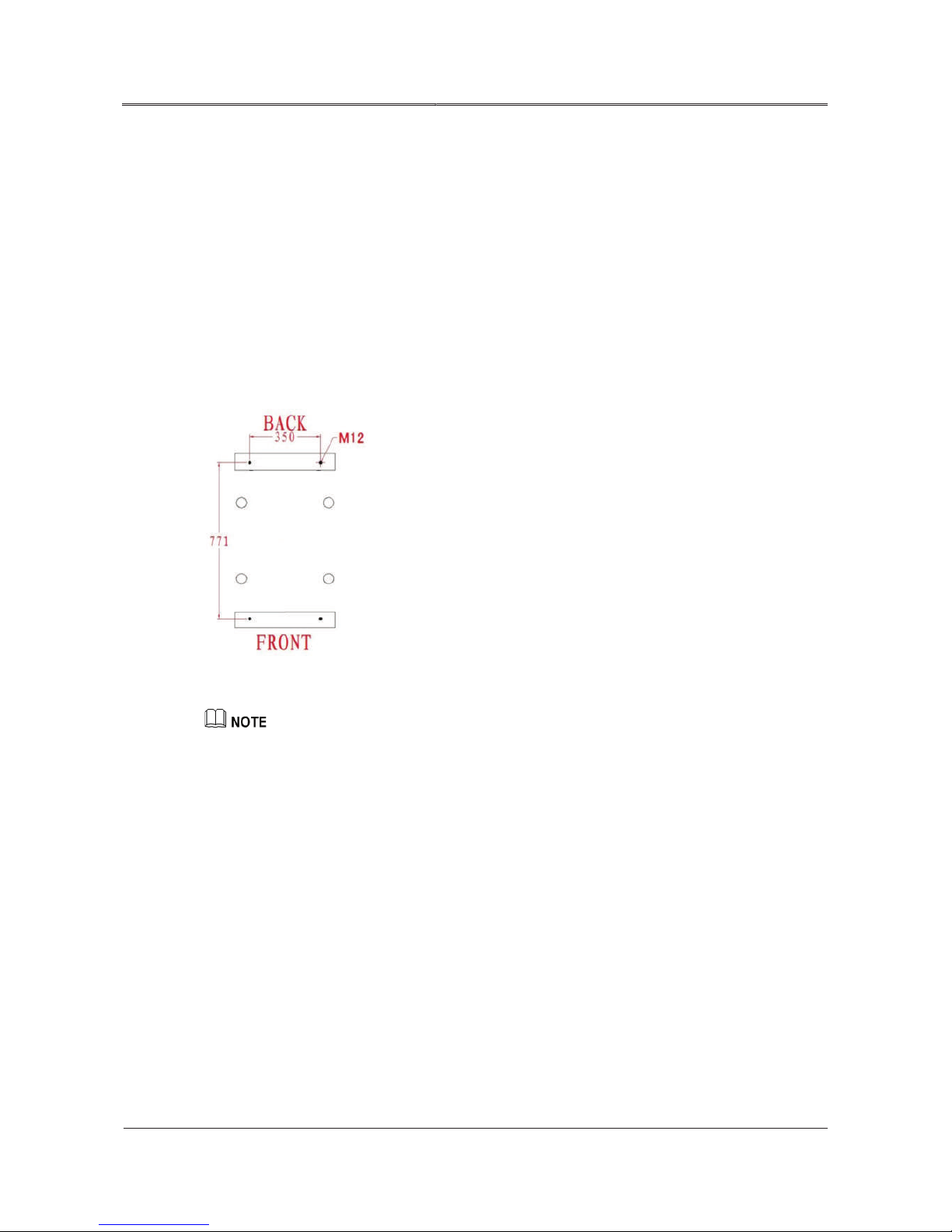
Step 1 Determine the installation position, set four M12 expansion bolts into the ground following
the measurements in Figure3-2.
Figure3-2 Installation dimension
Required interval: 771mm×350mm. The exposed height of expansion bolt should be within 50mm,.
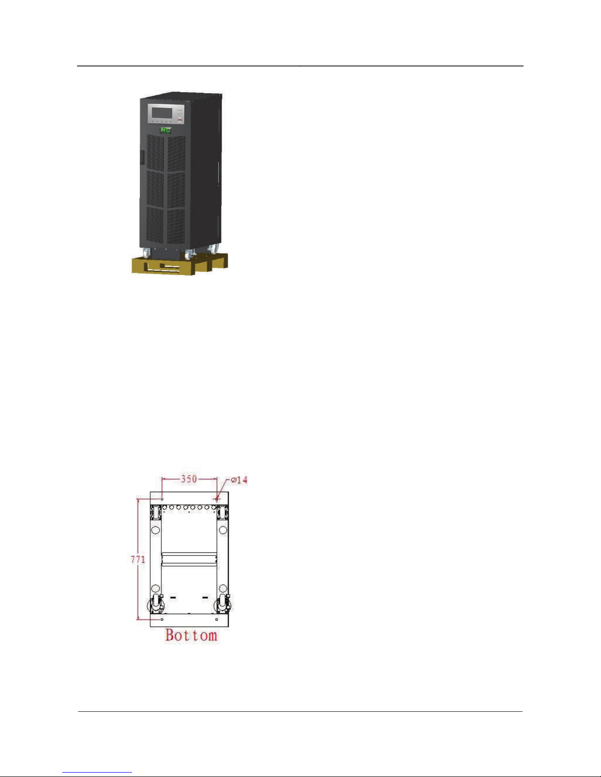
Step 2 Take out the UPS from the package. The appearance is as shown in Figure3-3.
Page 27
19
All rights reserved ©N1 Critical Technologies, Inc.
NE Series (20-30kVA)
User Manual
Chapter 3 Installation
Figure3-3 Appearance
Step 3 Rotate the four UPS “feet” in a counter-clockwise direction evenly until the four feet can support
the device completely. Remove the bolts connecting the UPS to the pallet. Detach the fixed
board from front and rear UPS plates, then rotate the 4 support feet clockwise, ensuring they
go all the way up into the UPS. This will put the weight of the device on the wheels. Attach
ramp in front of the UPS, aligning it with the pallet. Loosen the brakes of front wheels and roll
the UPS to the ground slowly. Use multiple persons as UPS unit is heavy. Push the UPS into
position with the expansion bolts. Lower the four support feet counter-clockwise until they
reach the floor to stabilize the unit. Lock the UPS into place with the expansion bolts and
corresponding nuts.
Figure3-4 Bottom structure
Page 28

20
All rights reserved ©N1 Critical Technologies, Inc.
NE Series (20-30kVA)
User Manual
Chapter 3 Installation
The exposed height of expansion bolt should be within 50mm.
----End
3.8 Electrical Connection
3.8.1
Wiring for Single-unit (NE##L & NE##PL models)
Connect the within cables to corresponding terminals and ensure reliable connection.
While wiring, please ensure that the contact of input and output cables, input and output
terminals is reliable. Avoid bad connection or reverse connection.
When used in signal-unit, the live wire and neutral wire of bypass do not need to connect with
other wires. The input neutral wire and output neutral wire share the same neutral wire
terminal.
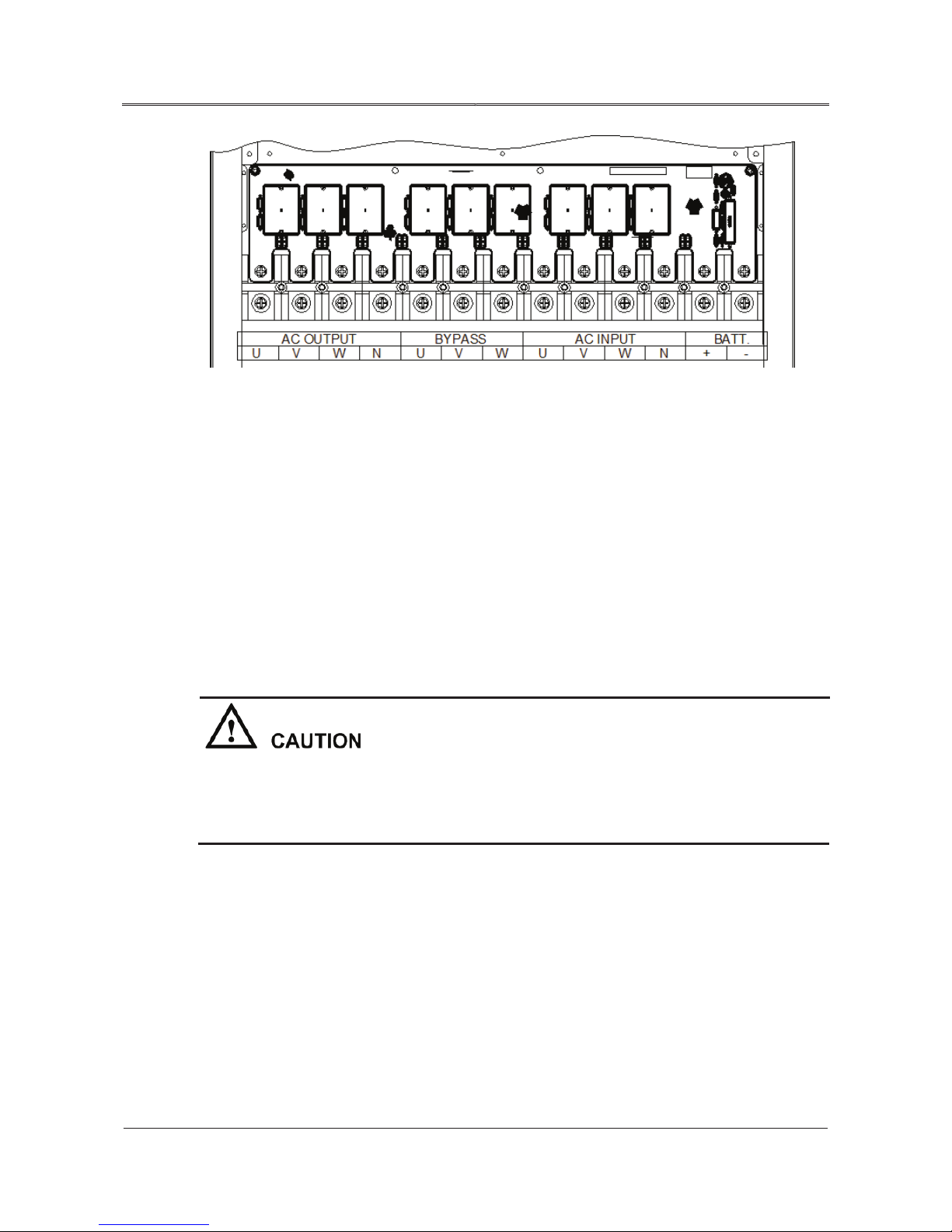
Step 1 Open the shrouding cover at the bottom of rear plate, you can see the input and output terminals.
The terminals are battery, mains, bypass and output separately, in proper order from right to
left.
Step 2 Connect the protective ground wire to the binding post of the UPS. The UPS cabinet should
be grounded.
Step 3 Connect the input of UPS to mains by input cables.
----End
The terminal wiring of NE Series (20-30kVA) UPS is as shown in Figure3-6.
The three-phase live wires in the figure are marked by U, V, W, which separately
corresponding phase-A, phase-B, phase-C, or phase-R, phase-S, phase-T.
Page 29
21
All rights reserved ©N1 Critical Technologies, Inc.
NE Series (20-30kVA)
User Manual
Chapter 3 Installation
Figure3-6 The wiring terminal of NE Series (20-30kVA) UPS
3.8.2 Wiring for Series System (NE##PL models ONLY)
The wiring way of series hot standby system is as follows.
Step 1 Dismantle the cover of terminal bar at the back of the UPS, then you can see load disconnectors
and wiring terminal. The load disconnector are respectively battery, mains, bypass,
maintenance bypass, output from left to right, thereinto, the battery disconnector is optional.
Step 2 Dismantle the short-connected bar between bypass switch and mains switch of UPS 1, and
input neutral wire of UPS 1. Connect the three-phase output live wire of UPS 2 to bypass
switch of UPS 1 according to the phase sequence. Connect the output neutral wire of UPS 2
to input neutral wire of main UPS.
The phase sequence of mains input cannot be connected reversely, or the UPS will not start
normally, and the touch screen will prompt wrong phase sequence. If the input phase
sequence wrong, it is necessary to exchange properly.
Step 3 Connect the mains input of UPS 1 to the mains input of UPS 2.
Step 4 Other wiring is the same as the single unit described in 3.9.1.
----End
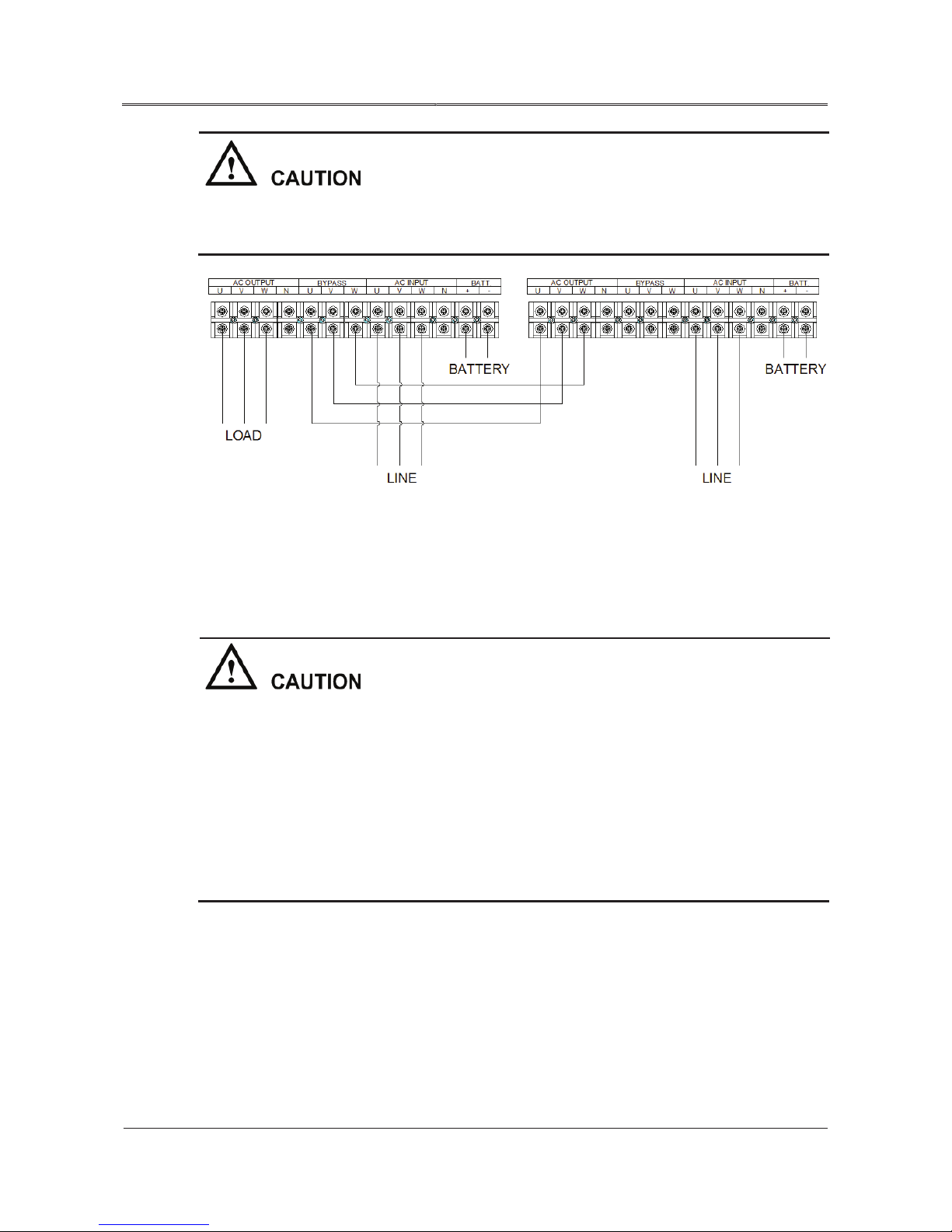
The terminal wiring of NE Series (20-30kVA) UPS is as shown in Figure3-7
Page 30
22
All rights reserved ©N1 Critical Technologies, Inc.
NE Series (20-30kVA)
User Manual
Chapter 3 Installation
Before wiring, please dismantle the short-connected bar between bypass switch and mains
switch of UPS 1, and input neutral wire N of UPS 1 firstly.
Figure3-7 The terminal wiring of NE Series (20-30kVA) UPS
3.8.3 Wiring for Parallel System (NE##PL Models ONLY)
After installing the battery of each parallel system and UPS, connect the parallel wires. The wiring way
is as follows.
The phase sequence of mains cannot be connected inversely, or the device will not start
normally, at the same time, the touch screen displays wrong phase sequence. If the phase
sequence is wrong when startup, it is necessary to change them to correct status.
The connection, phase sequence of each unit’s AC input should be strictly in accordance with
others, ensure that the bypass power supply of parallel system are the same.
Before powering on, check that the phase of the two UPSs input three-phase is corresponding,
then measure that the input voltage between U, V, W should be less than 5V.
Step 1 Open the rear sealing plate of each paralleled UPS, and then dismantle the cover of terminal
bar.
Step 2 Connect the AC input of each paralleled UPS to mains.
Step 3 Connect the AC output of each paralleled UPS to load or distribution cabinet of load.
Step 4 Connect the battery input port of each paralleled UPS to corresponding battery group.
Page 31
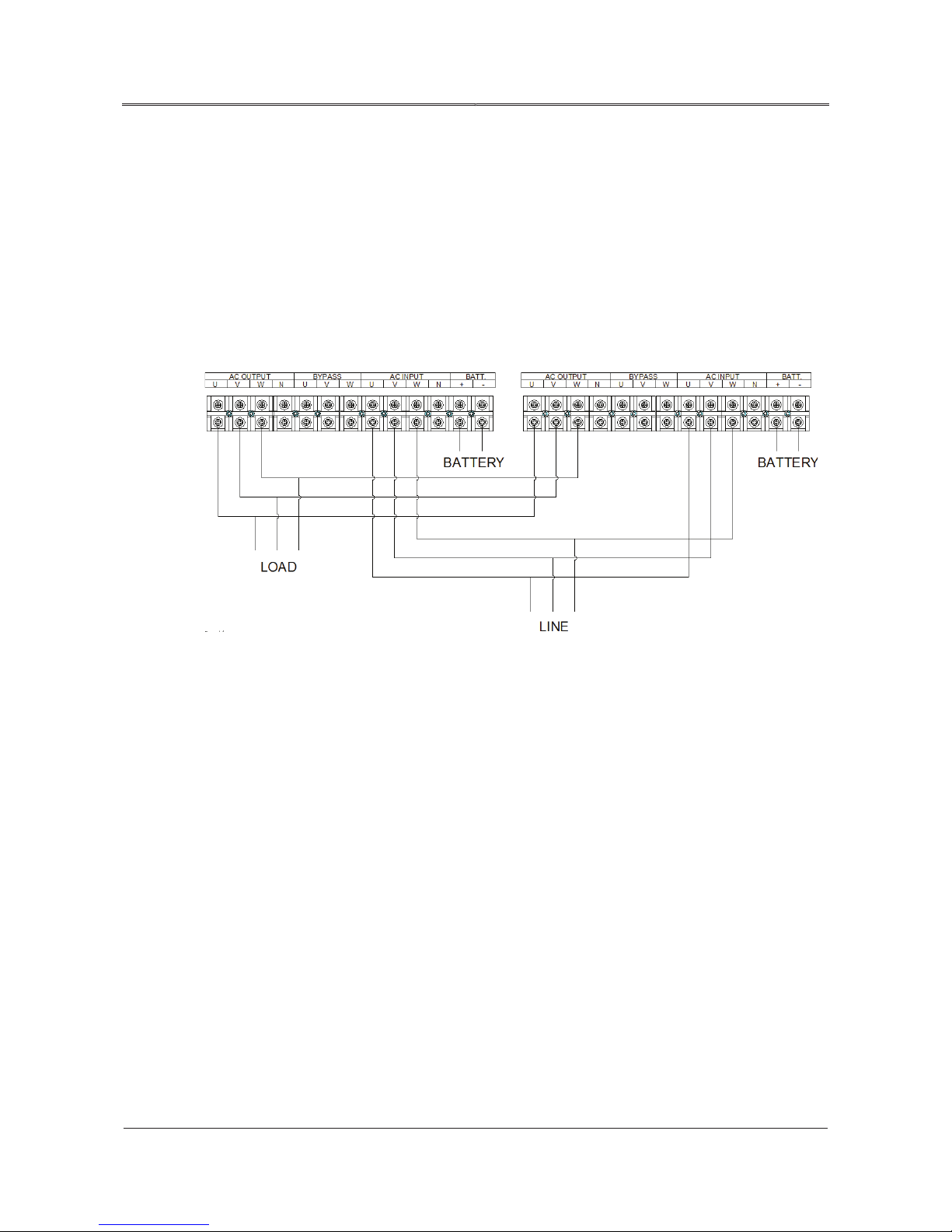
23
All rights reserved ©N1 Critical Technologies, Inc.
NE Series (20-30kVA)
User Manual
Chapter 3 Installation
Step 5 Connect the parallel communicating connector of each paralleled UPS by parallel cables
(shielding communication wire), and fasten the corresponding parallel communicating
connector by bolts.
----End
The lead of UPS 1’s and UPS 2’s output N, U, V, W are from the terminal bar of UPS, and short
circuited on load or distribution cabinet of load. The connection of parallel system is as shown in
Figure3-8.
Figure3-8 The terminal wiring of NE Series (20-30kVA) UPS
3.9 Connect Communication Wires
3.9.1
RS232 Communication
The RS232/RS485 communication port is located in the rear of the device. It can realize the remote
monitoring for input voltage, frequency, output voltage, frequency, load, etc. of the UPS, and it also
can achieve remote power on/ off operation.
Definition for RS232 pins:
DB9(RS232/485): 6P, RXD of UPS;
DB9(RS232/485): 7P, GND;
DB9(S232/485): 9P, TXD of UPS.
Page 32
24
All rights reserved ©N1 Critical Technologies, Inc.
NE Series (20-30kVA)
User Manual
Chapter 3 Installation
3.9.2 RS485 Communication
The RS232/RS485 communication port is located in the rear of the device. It supports remote
communication. It can realize the remote monitoring for input voltage, frequency, output voltage,
frequency, load, etc. of the UPS, and it also can achieve remote power on/ off operation.
Definition for RS485 pins:
5P of DB9(RS232/485): A;
7P of DB9(RS232/485): GND;
8P of DB9(RS232/485): B.
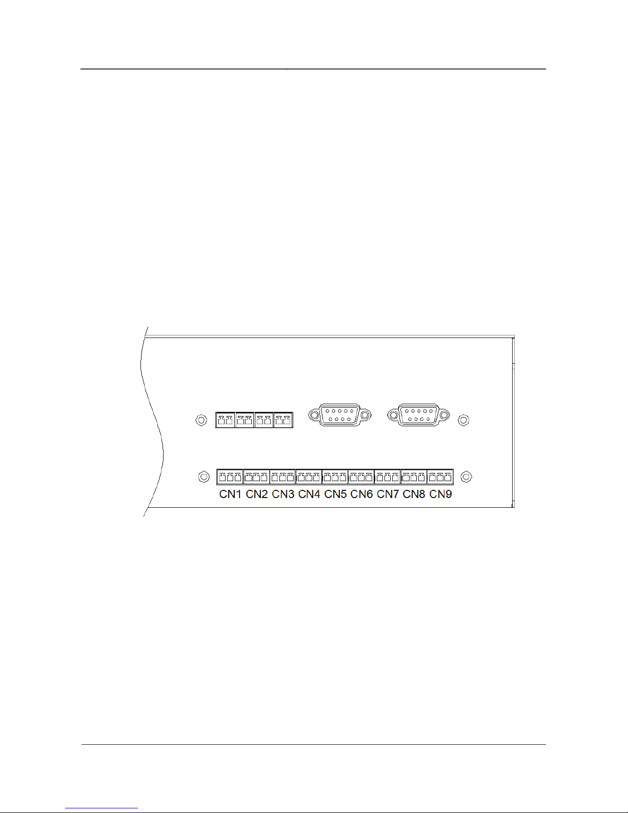
3.9.3 Dry Contact Communication
The dry contact communication board is as shown in Figure3-9.
Figure3-9 Dry contact communication board
The illustration for external ports of dry contact communication board is as shown in Table3-5.
Page 33

25
All rights reserved ©N1 Critical Technologies, Inc.
NE Series (20-30kVA)
User Manual
Chapter 3 Installation
Table3-5 Illustration for external ports of dry contact communication board
1~3P
4~6P
7~9P
10~12P
13~15P
16~18P
19~21P
22~24P
25~27P
Inverter fault
Battery low-voltage
Maintenance bypass
Inverting
Overload
Mains fault
Bypass status
Fan fault
Anti-reverse feedback contactor
3.9.4 SNMP Card (optional)
It realizes the remote control for input voltage, frequency, output voltage, output voltage, frequency,
load, etc. of UPS, and it also can achieve remote control for power on/off.
Before leaving factory, the controlling wire of the UPS has been fixed on the installation port which
marked with SNMP. When installing, it only needs to connect the controlling wire and SNMP card.
3.9.5 Battery Switch
The UPS is equipped with a battery switch.
3.9.6 Anti-reverse Feedback Contactor (Included on “P”Models)
If the main power supply cannot be used, voltage or energy inside the UPS may be reversed (feedback)
to any input terminal directly or indirectly and generate reverse feedback electricity (back-feed). To
decrease the electric shock caused by reversed feedback, it is necessary to have an anti-reverse feedback
device on Parallel-Connectable (P-Series) models so the device meets the IEC62040-1-2 Standards.
Page 34

26
All rights reserved ©N1 Critical Technologies, Inc.
NE Series (20-30kVA)
User Manual
Chapter 3 Installation
The anti-reverse feedback device is built-in to P-Models only. For the UPS models without
built-in anti-reverse feedback device, please check if there is dangerous voltage in main
power wiring terminals before wiring or maintenance.
Page 35

27
All rights reserved ©N1 Critical Technologies, Inc.
NE Series (20-30kVA)
User Manual
Chapter 4 Operation Guide
Chapter 4 Operation Guide
This chapter mainly introduces the operation guide for the UPS, including pre-startup checklist,
precautions for operating UPS, operation and running, operation of parallel system, operation of
maintenance switch, etc.
4.1 Check before Startup
4.1.1
Check the Electrical Connection
No. Check item
Confirm that battery switch (BATTERY), mains switch (MAINS), bypass switch
1
2
3
4
5
(BYPASS), maintenance bypass switch (MAINTENANCE BYPASS), output switch
(OUTPUT) of UPS 1 are all off.
Confirm that the total load capacity matches with the capacity of UPS and make sure the
load is off.
Confirm that there is no short-circuit between input live line and input neutral line, input
live line and input ground line. Confirm that there is no short-circuit in output.
Test the AC voltage of UPS 1’s mains input on the input terminal (POWER). The voltage of
AC input should be within the range of 85V-135Vac, or it needs to start the UPS without
mains.
If the UPS 1 is equipped with battery switch, measure the DC voltage of battery input
terminal (BATTERY), if the UPS is not equipped with battery switch, measure the DC
voltage of battery cabinet input terminal (BAT.), and check the wire connection of battery
cabinet and UPS. It is required that the voltage of battery group is the voltage required by
the device, which is to avoid wrong wire connection of battery.
6 Check if the color of AC cables is in accordance with electrical codes.
7 Check if the wiring of cabinet is firmly attached.
Page 36

28
All rights reserved ©N1 Critical Technologies, Inc.
NE Series (20-30kVA)
User Manual
Chapter 4 Operation Guide
No. Check item
8 Check if the safe identification of AC power distribution unit is complete.
9 Check if the cable connection is tight.
10 Check if the battery is connected in proper polarity and sequence.
11 Check if the cable identification is correct.
12
13
Check if the wiring is neat, and if the cable connection is in accordance with the
electrical codes.
Check if the equipment installation and wiring is advantageous to the transformation,
expansion and maintenance of the system in future.
4.1.2 UPS Testing
Test UPS: close the battery switch, mains switch, bypass switch, and start the UPS. After the UPS
working stably and stay in mains inverting to output, disconnect the mains switch to simulate the mains
outage, the UPS will turn to battery inverting to output, at the same time, the buzzer beeps slowly; then
disconnect the battery switch to simulate the status of protection for battery low-voltage, the UPS will
turn to bypass output, and the buzzer beeps constantly to alarm.
4.2 Precautions for Operating UPS
Before starting the UPS, check whether the load is proper. The load must not exceed the rated
output power of the UPS. Otherwise, the UPS may turn into overload protection status.
Do not use the <ON> and <OFF> switch on the UPS panel as the power supply switches of loads.
Do not start the UPS frequently.
When the mains supply is off, start the generator firstly if the UPS needs to be connected to it. Do
not connect the UPS to the generator before the generator works stable. Otherwise, the UPS or the
load may get damaged. Switch off the UPS before switching off the generator.
Prior to the first startup of UPS, the power and UPS needs to be checked. Only with passing the
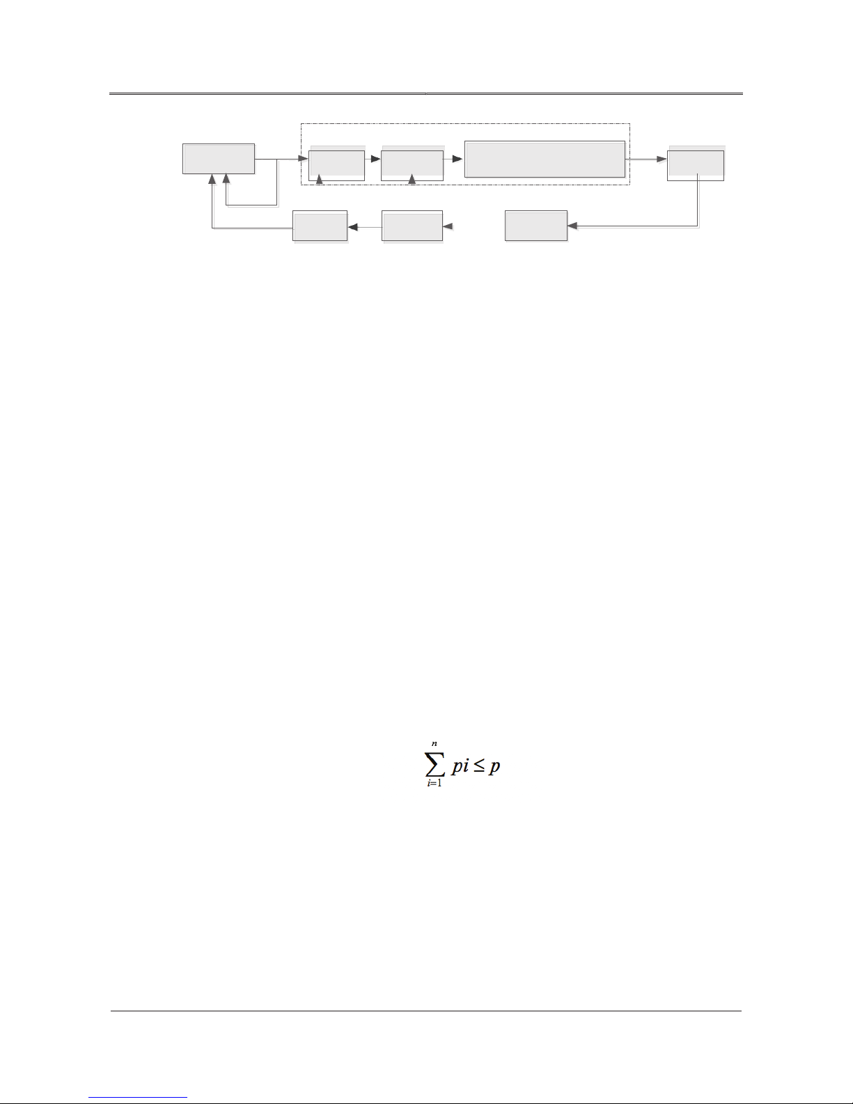
examination, power the UPS. If UPS hasn’t been used for a long time, it also needs to be checked
before startup. Operation procedure is showed in Figure4-1.
Page 37
29
All rights reserved ©N1 Critical Technologies, Inc.
NE Series (20-30kVA)
User Manual
Chapter 4 Operation Guide
-
-
-
n
Startup
If it is left unused
Observe indicator light on panel
Qualified
Check before
powering on
Shutdown
Power
Failure
Running
StartupPower on
Inquire system information
stable
loads
for longtime
Figure4-1 Operation Procedure
4.3 Operation
4.3.1
Check Before Power-on
Before power on, please check according to following steps. If the check is OK, the UPS can be
started.
Step 1 Connect the input power end with rated input power.
Step 2 Check load.
off
Shutdown
loads
If you will stop using UPS
Ensure that the load is non-inductive load. The output of UPS cannot connect with
inductive load, such as motors, fans, air-conditions. The power of these loads is
generally supplied by power-grid directly.
Ensure that the load is closed and the load capacity does not exceed the rated output
capacity of UPS, or, it will cause the protection for overload. The calculation of load
capacity is as follows.
The load capacity of NE series UPS is designed as 90% nominal rated power of resistive load,
the most bearable number n of computer is estimated as follows:
p is the output capacity (VA) of UPS, pi is the power of load i.
Step 3 Ensure that there is no short-circuit between live wire and neutral wire, live wire and earthing
wire of the UPS input. As the same to confirm the output of UPS with no short-circuit.
Step 4 The switches of UPS input and output are all off.
Step 5 Ensure that the computer or other devices are closed.
----End
Page 38

30
All rights reserved ©N1 Critical Technologies, Inc.
NE Series (20-30kVA)
User Manual
Chapter 4 Operation Guide
4.3.2 Start the UPS
Please perform the following steps to start the UPS.
Step 1 Close the input switch of bypass (BYPASS).
The power board start to work and the touch screen starts to display.
Step 2 Close the input switch of rectifier (MAINS).
If the mains input power is right, the rectifier will activate automatically, 30S later, the DC
voltage will be set up completely, the rectifier indicator (AC/DC) on the panel will be on.
Step 3 Close the input switch of battery (BATTERY).
Close the switch of external battery, ensure that the LED indicator on the detecting board of
battery polarity is off and the buzzer is silent, and then close the battery switch of the UPS.
Step 4 Start the inverter system.
Press the ON combination buttons on the panel for 1S to start the inverter, the DC/AC indicator
will be on. 30S later, close the output switch, the UPS will invert output normally. It also can
be performed by touch screen to start the UPS.
----End
4.3.3 Start Load
Step 1 See the running status of UPS according to the indicator light on panel. When lights indicate
that UPS works in mains mode or battery mode, it means UPS can power loads.
Step 2 Let UPS keep running without load for 10min and then turn on loads in sequence: big-power
load to small-power load.
----End
4.3.4 Shutdown UPS
Please perform the following steps to shut down the UPS.
Step 1 Disconnect the switches of the load.
Step 2 Disconnect the output switch.
Page 39

31
All rights reserved ©N1 Critical Technologies, Inc.
NE Series (20-30kVA)
User Manual
Chapter 4 Operation Guide
Before disconnecting the output switch, please ensure that the output load is not in use, or,
once the output is disconnected, there will be no electric power output, which will cause the
power outage for use loads.
Step 3 Close the inverter system.
Press the OFF combination buttons on the panels for 1S, the inverter will be closed. The
operation also can be performed through touch screen.
Step 4 Disconnect the battery input switch, including the UPS’s input switch (BATTERY), battery
cabinet input switch and other external battery input switches.
Step 5 Disconnect the rectifier input switch (MAINS).
Disconnect the rectifier input switch, the rectifier will not transfer DC power from mains to
DC BUS, DC BUS will release electric power slowly, about 5 minutes later, the voltage will
drop to a safe voltage. To ensure safety, only start maintenance to the UPS after 10 minutes.
Step 6 Disconnect the bypass input switch (BYPASS).
Disconnect the bypass input switch, after the touch and LED off, the UPS will be shut down
completely.
----End
4.4 Operation for Manual Maintenance
To perform maintenance without any power interruption, follow the instructions.
The following operations should be done by professionals. Manufacturer doesn’t take the
responsibility for problems caused by unauthorized or untrained persons.
Step 1 Press the OFF button on the panel to close the inverter.
Step 2 After the BYPASS indicator on the panel lighting on, close the switches of rectifier mains and
battery (the battery switch of the UPS (if equipped) and battery cabinet switch are all off).
Take out the hanging lock of maintenance switch, place the switch of manual maintenance to
“ON”, then turn off the switch of bypass power (BYPASS) and output switch (OUTPUT), and
then start maintenance.
Page 40

32
All rights reserved ©N1 Critical Technologies, Inc.
NE Series (20-30kVA)
User Manual
Chapter 4 Operation Guide
During maintenance for the UPS, the output switch (OUTPUT) is strictly prohibited to close.
Step 3 After maintenance, turn on the switch of bypass power (BYPASS), output switch (OUTPUT).
After the power work normally and the BYPASS indicator light on, place the manual
maintenance switch to OFF, and recover the hanging lock, then thee load turns to bypass to
supply power.
Step 4 Shut down the UPS according to 4.3.4 Shutdown UPS.
----End
4.5 Operation for Parallel System (P-Models Only)
4.5.1
Start Parallel System
Don’ t turn on loads before starting parallel system completely. Make sure all switches of
parallel system’ s load are disconnected and all the input and output power lines are
connected correctly.
Perform the following steps to start the parallel system.
Step 1 Close the bypass switch of the UPS 1, the power board start to work, and the touch screen
begin to display.
Step 2 Close the mains switch of the UPS 1.
If the input power is normal, the rectifier will activate automatically. 30S later, the voltage of
DC BUS is set up completely, and the AD/DC indicator on the panel lights on.
Step 3 Close the battery switch of the UPS 1 (if there is no battery switch, close the battery cabinet
switch and external switches).
Step 4 Close the battery switch to the rectifier to start to charge for the battery.
Step 5 Start the inverter system of the UPS 1.
Page 41

33
All rights reserved ©N1 Critical Technologies, Inc.
NE Series (20-30kVA)
User Manual
Chapter 4 Operation Guide
Press the ON button on the panel for 1S to start the inverter system. 30S later, close the output
switch of the UPS, the UPS will invert to output normally. Measure the output voltage and
frequency of the UPS is normal by multimeter.
Normal => Step 6
Abnormal => Step 12
After the output is normal, it is necessary to close the output switch of the main UPS again.
But the main UPS should be on.
Step 6 Start the UPS2 according to Step1 to Step3.
Step 7 Measure whether the output voltage and frequency of the UPS2 is normal (the output switch
of UPS2 is off).
Normal => Step 8
Abnormal => Step 12
Step 8 Measure whether the output voltage difference of the UPS 1 and UPS 2 is normal.
If the voltage difference of the two UPSs is less than 10V, it means the phase-lock of the two
UPSs in mains status is normal.
Normal => Step 9
Abnormal =>Step 12
Step 9 Disconnect the mains switches of the two UPSs, measure whether the voltage difference for
output live wires of the two UPSs is normal.
If the voltage difference is less than 10V, it means the phase-lock of the two UPSs in battery
status is normal.
Normal => Step 10
Abnormal => Step 12
Step 10 Close the output switch of UPS 2, and measure whether the paralleled three-phase output
voltage is normal.
If the measured voltage is less than 5V, it means the output of the UPS 2 is normal.
Normal => Step 11
Abnormal =>Step 12
Step 11 Close the mains switches of the two UPSs, and measure whether the paralleled output loop
current is normal.
Page 42
34
All rights reserved ©N1 Critical Technologies, Inc.
NE Series (20-30kVA)
User Manual
Chapter 4 Operation Guide
If the output loop current is less than 30A, it means the output voltage of parallel system is
Disconnect the parallel units
normal.
Normal =>Step 13
Abnormal =>Step 12
Step 12 After powering down and getting rid of faults, perform Step 1.
Step 13 After testing normally, close the switch of user load, then the starting of parallel system will
be finished.
At this moment, the parallel system can supply power for load. The power on sequence of load,
please refer to the requirements of single unit.
----End
4.5.2 Shut Down Parallel System
Step 1 Close all loads.
Step 2 Close each inverter according to the shutdown steps of the UPS.
Step 3 Perform the shutdown steps of the UPS, and disconnect the relative input and output switches
of each UPS.
----End
It is recommended that you do not switch on or switch off the parallel system frequently when it is
working properly.
4.5.3 Exit Parallel System Online
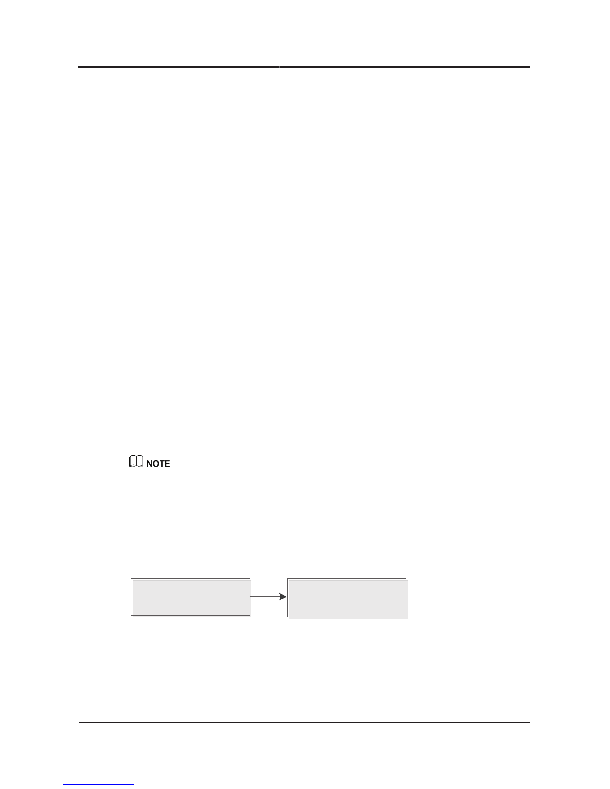
When one UPS fails, it will exit from the parallel system automatically. In addition, an audible and
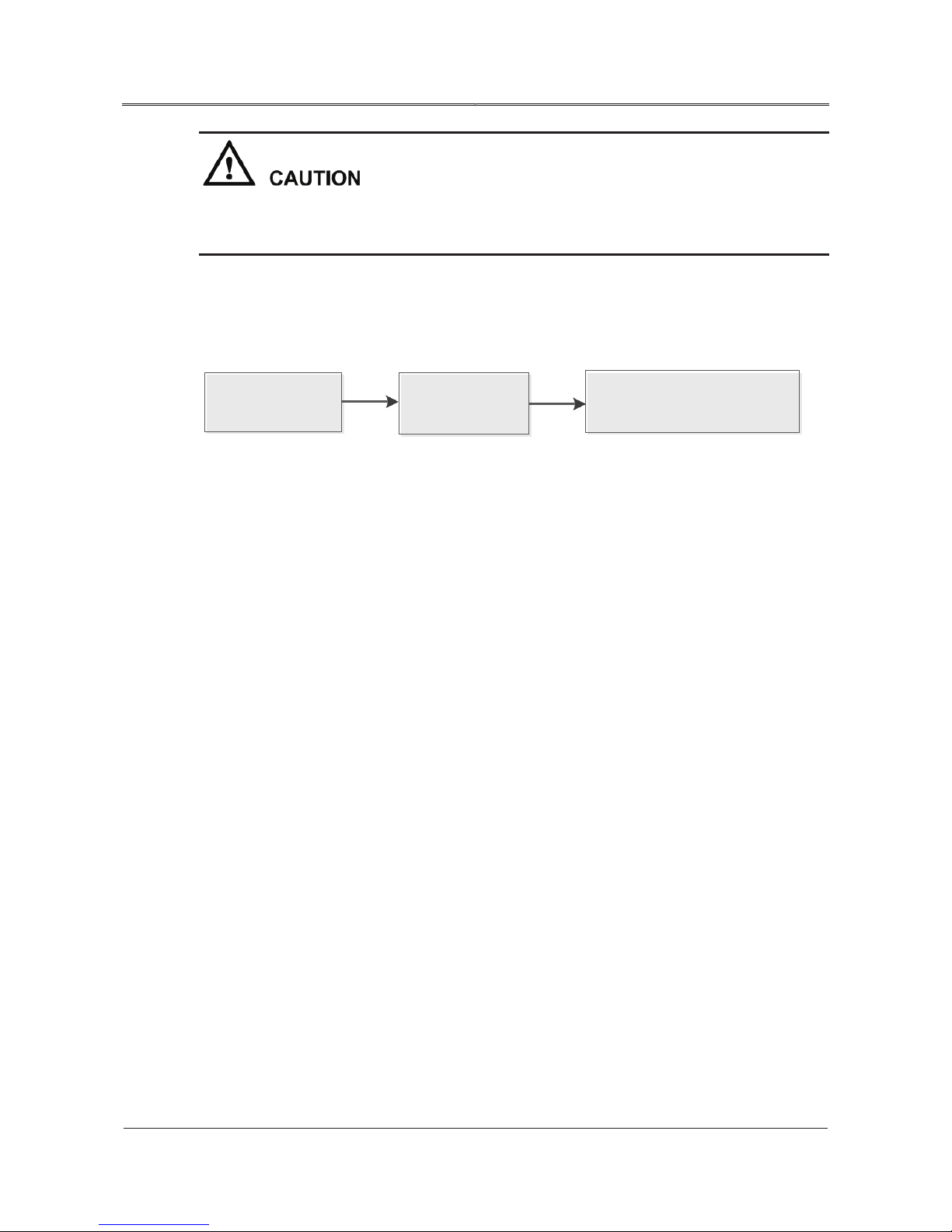
visual alarm is generated. You can follow the procedure showed in Figure4-2to exit the faulty UPS to
achieve online thermal maintenance or replacement.
Close the fault UPS according
to shutdown procedure
Figure 4-2 Exit a faulty UPS
air switch to UPS in the
parallel distribution box.
Page 43
35
All rights reserved ©N1 Critical Technologies, Inc.
NE Series (20-30kVA)
User Manual
Chapter 4 Operation Guide
When the parallel system is working properly, do not exit the UPS’ output from parallel
system without switching off the UPS. Otherwise, the parallel system cannot work properly.
4.5.4 Enter a UPS Online
Follow the procedure showed in Figure4-3 to join one or more UPS to a parallel system online. After
the new UPS run properly, they will join the parallel system and run with average current.
Install the adding
parallel unit
Figure 4-3 Enter a UPS online
Close the adding
UPS air switch
4.5.5 Redundancy Function of the Parallel System
When adopting the design of 2+1 parallel redundant backup, the total output load cannot be greater
than 2 times the rated output of a single-unit. When one single-unit is in fault, the single-unit can enter,
exit freely and does not influence the operating of parallel system, which can enhance the reliability of
the system. When the load exceeds the above capacity, the overload single-unit (more than N/(N+1)
times rated output of single-unit), it will send alarm. For example, for the system with double UPS to
backup, if the load of single-unit exceeds 50% rated power, it will send overload alarm.
4.6 Operation of Touch Screen
The touch screen provides a graphical user interface for the UPS. By touch screen, indicator light and
user-friendly operation system, users can easily browse the input, output, load, and battery parameters
of the UPS to get the current status and warning information of UPS in time and to see functions and
control UPS. Touch screen can also provide historical alarm log for users, and provide a reliable basis
for fault diagnosis.
Start the adding UPS in order
according to the UPS startup steps
4.6.1 Menu Structure of Touch Screen
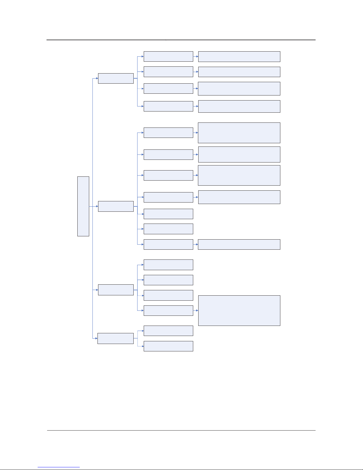
Menu structure of the touchscreen shows the function for inquiry and setting. The menu structure is as
shown in Figure4-4.
Page 44
36
All rights reserved ©N1 Critical Technologies, Inc.
NE Series (20-30kVA)
User Manual
Chapter 4 Operation Guide
Figure4-4 Menu structure of the touch screen
Product information
Log management
Screen setting
Battery testing
Battery management
System management
Output
Battery
Bypass
Mains
ON/OFF
Controlling
Silence buzzer
Product name\ model\ manufacturer\
production base\postcode\ service
hotline\SN\rectifier version\ inverter
version\ hardware version\system version\
protocol version\HMI version\ device status
User log
Event records
Information
Working status
Clear log\backup log
Restore default setting
Password setting
Date\time\backlight brightness\backlight
time\language
Display: battery voltage\battery current\
discharged capacity\test time\test status
Setting: standard test\deep test \cancel test
Charge current\ single floating charge
voltage\ single equalizing charge voltage
Setting
Bypass volt. Upper threshold\Bypass volt.
Lower threshold\bypass frequency
range\ECO mode\ECO volt. Upper
threshold\ECO volt. upper threshold
Phase voltage\phase current\frequency\load
\KVA\KW \PF
Voltage\current\temperature\remaining
time\remainder capacity\status
Phase voltage\phase current\frequency
Monitoring
Phase voltage\phase current\frequency
Welcome page
4.6.2 Main Page
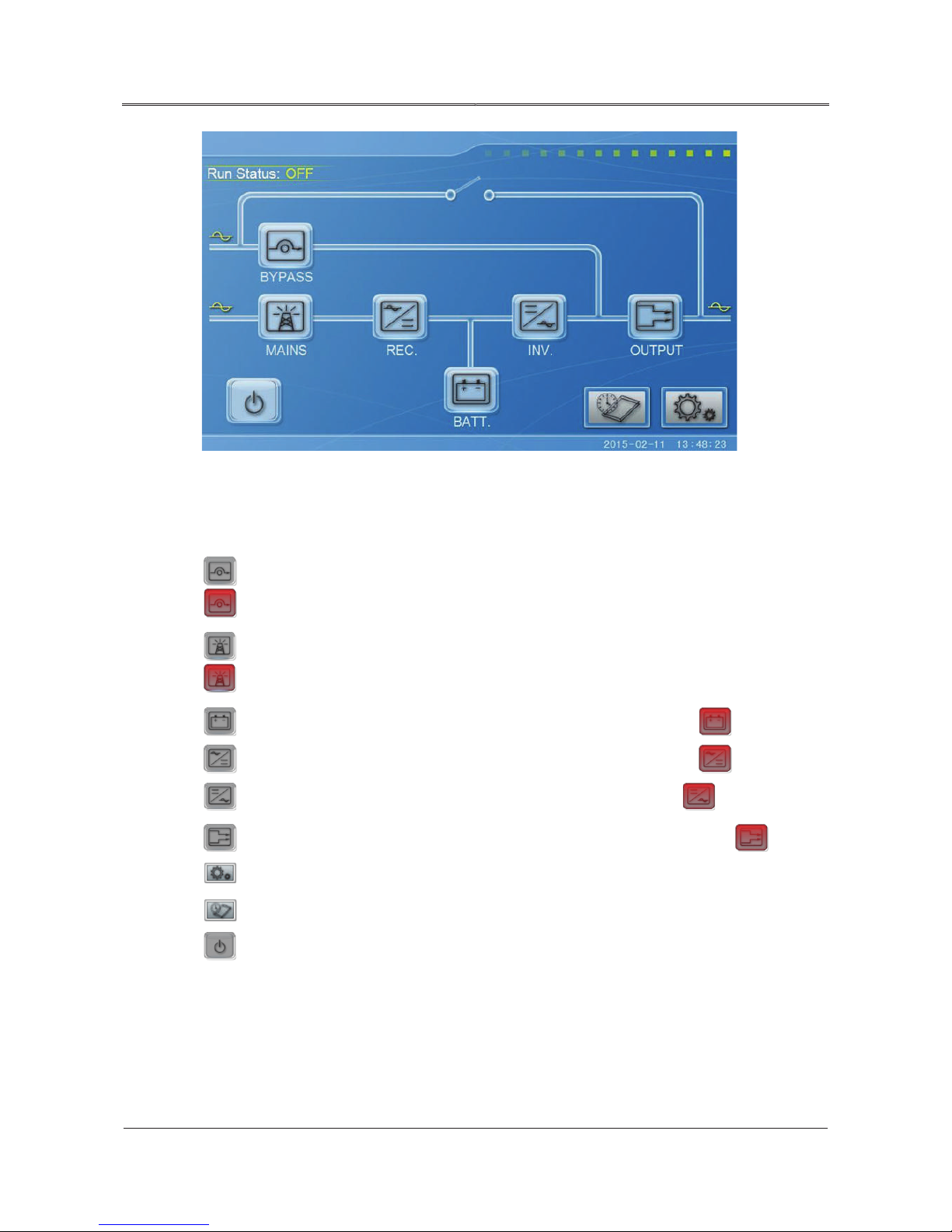
It will enter system monitoring main page after powering on, as shown in Figure4-5.
Page 45
37
All rights reserved ©N1 Critical Technologies, Inc.
NE Series (20-30kVA)
User Manual
Chapter 4 Operation Guide
Figure4-5 Main page
It can realize the monitoring for system after entering main page. The meaning of each icon on the
main page is as follows.
: System bypass input status. If bypass input abnormal, the icon will flicker, and show as
.
: System mains input status. If the mains input abnormal, the icon will flicker, and show as
.
: Battery status. If the battery abnormal, the icon will flicker, and show as .
: Rectifying status. If the rectifier fault, the icon will flicker, and show as .
: Inverting status. If the inverter fault, the icon will flicker, and show as .
: System output status. If the output abnormal, the icon will flicker, and show as .
: system parameters setting.
: Information inquiry.
: Power on/off.
4.6.3 Work Status of the System
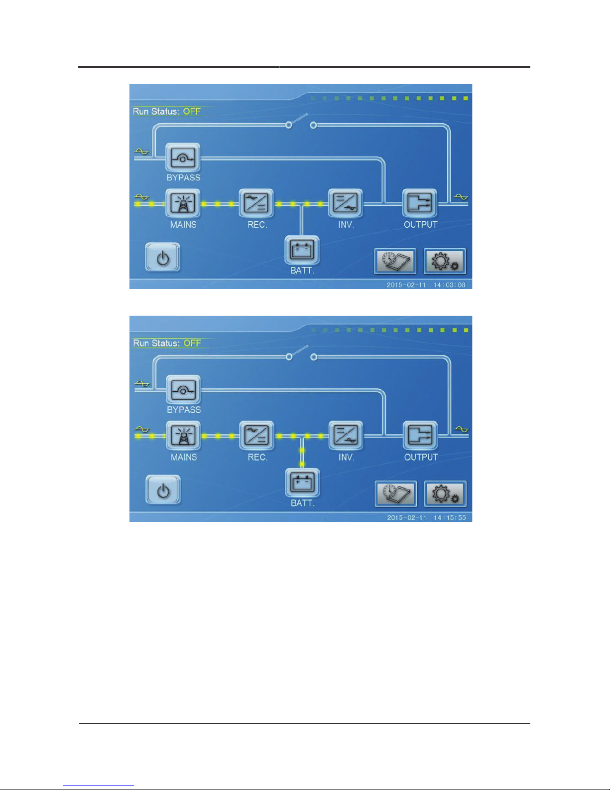
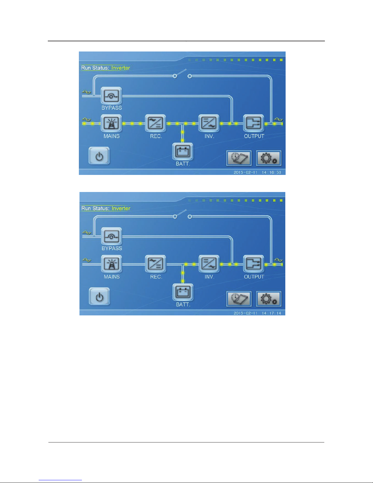
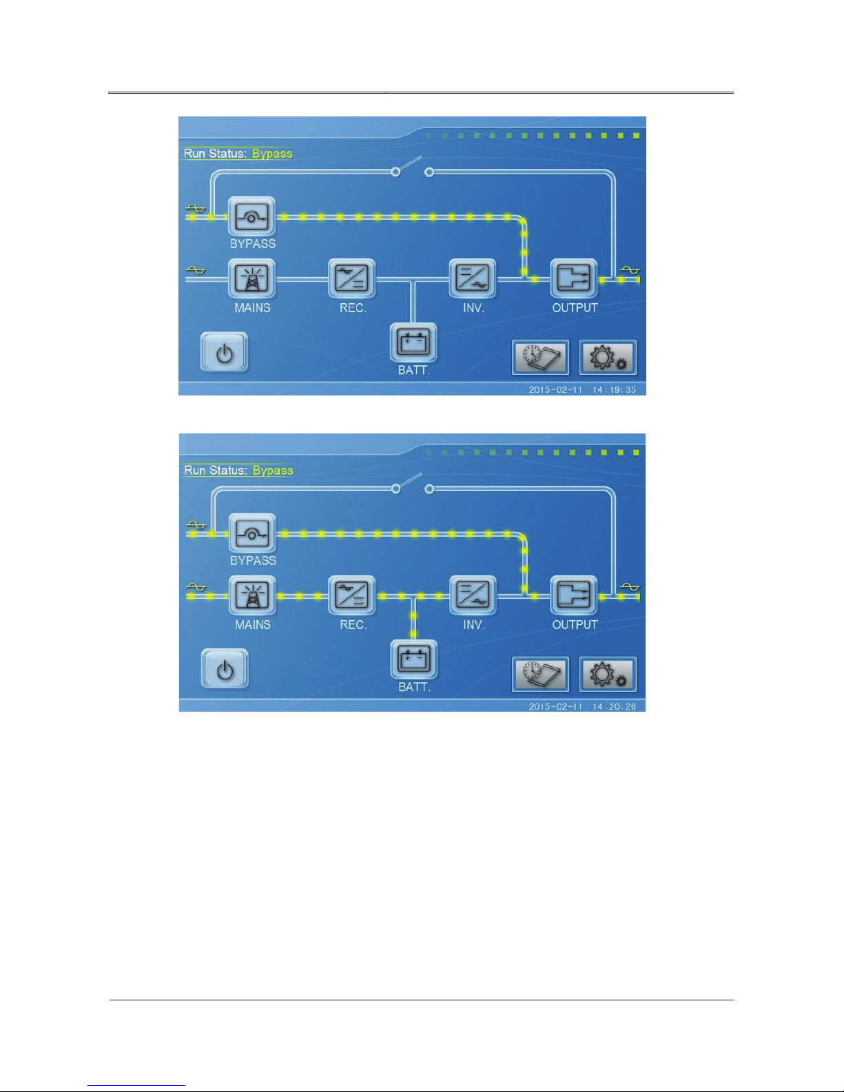
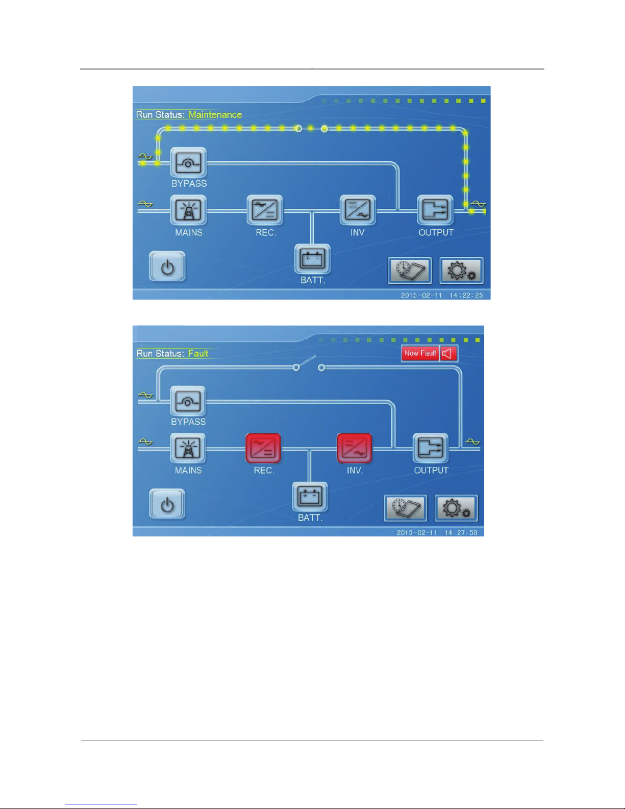
The work status and energy flow on the main page shows the running status of the system directly.
The energy flow of each work status is as follows.
Page 46
38
All rights reserved ©N1 Critical Technologies, Inc.
NE Series (20-30kVA)
User Manual
Chapter 4 Operation Guide
Figure4-6 Rectifier startup
Figure4-7 Battery is not connected to load, and the rectifier is started.
Page 47
39
All rights reserved ©N1 Critical Technologies, Inc.
NE Series (20-30kVA)
User Manual
Chapter 4 Operation Guide
Figure4-8 Rectifier inverting status (load is on main power with battery now protecting the load).
Figure4-9 Battery inverting status (battery is powering the load).
Page 48
40
All rights reserved ©N1 Critical Technologies, Inc.
NE Series (20-30kVA)
User Manual
Chapter 4 Operation Guide
Figure4-10 System bypass status
Figure4-11 Rectifier bypass status
Page 49
41
All rights reserved ©N1 Critical Technologies, Inc.
NE Series (20-30kVA)
User Manual
Chapter 4 Operation Guide
Figure4-12 System maintenance bypass output
Figure4-13 Protection for fault, and with no output
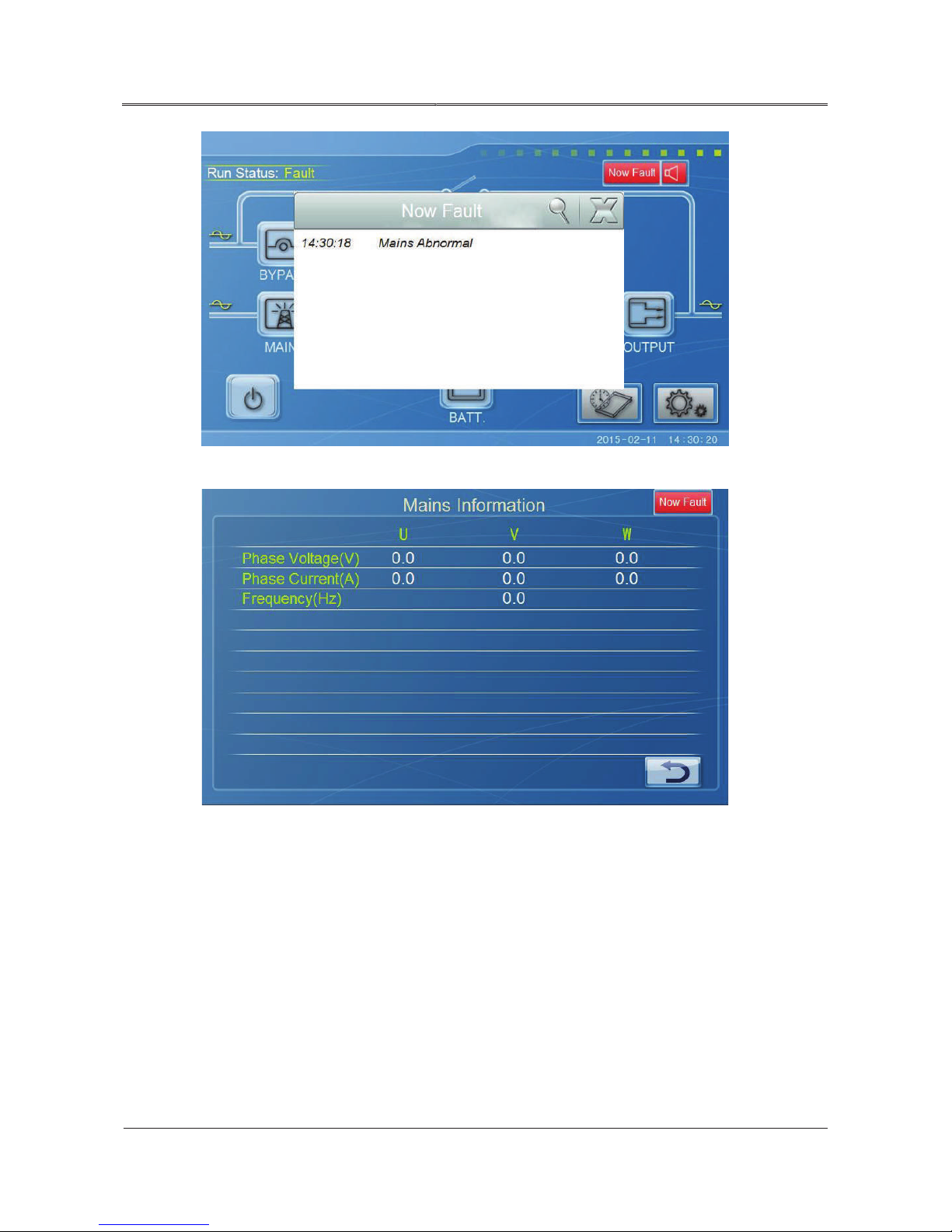
When the system occur abnormal condition, the system will popup fault window, at the same time,
there will be a “fault alarm” indicator on the top right corner of main page and information display
page, as shown in Figure4-14, Figure4-15.
Page 50
42
All rights reserved ©N1 Critical Technologies, Inc.
NE Series (20-30kVA)
User Manual
Chapter 4 Operation Guide
Figure4-14 Now Fault window
Figure4-15 Fault alarm indicator on Mains Information page
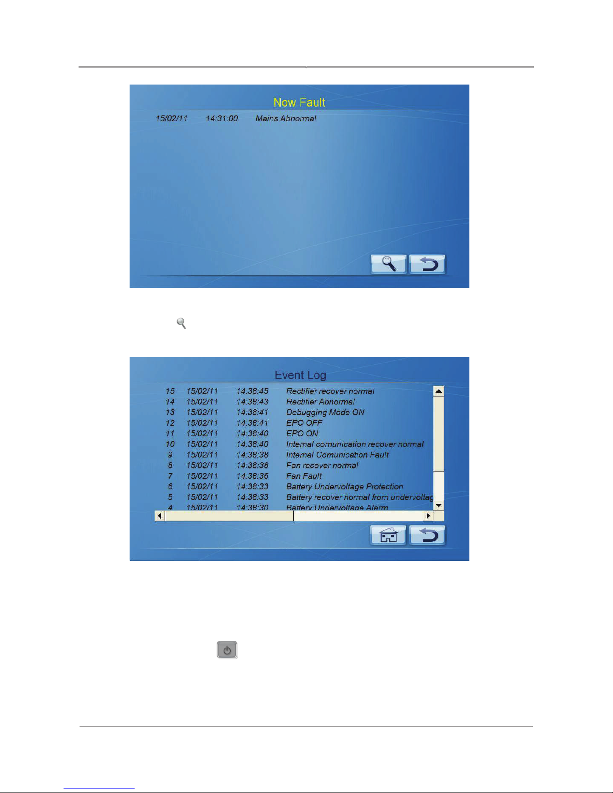
After closing the current fault window, click “now fault” indicator to display current fault
information, as shown in Figure4-16.
Page 51
43
All rights reserved ©N1 Critical Technologies, Inc.
NE Series (20-30kVA)
User Manual
Chapter 4 Operation Guide
Figure4-16 Now fault information
Click the
17.
Figure4-17 Event log information
button on Now Fault page to look up the event log information, as shown in Figure4-
4.6.4 Controlling Function
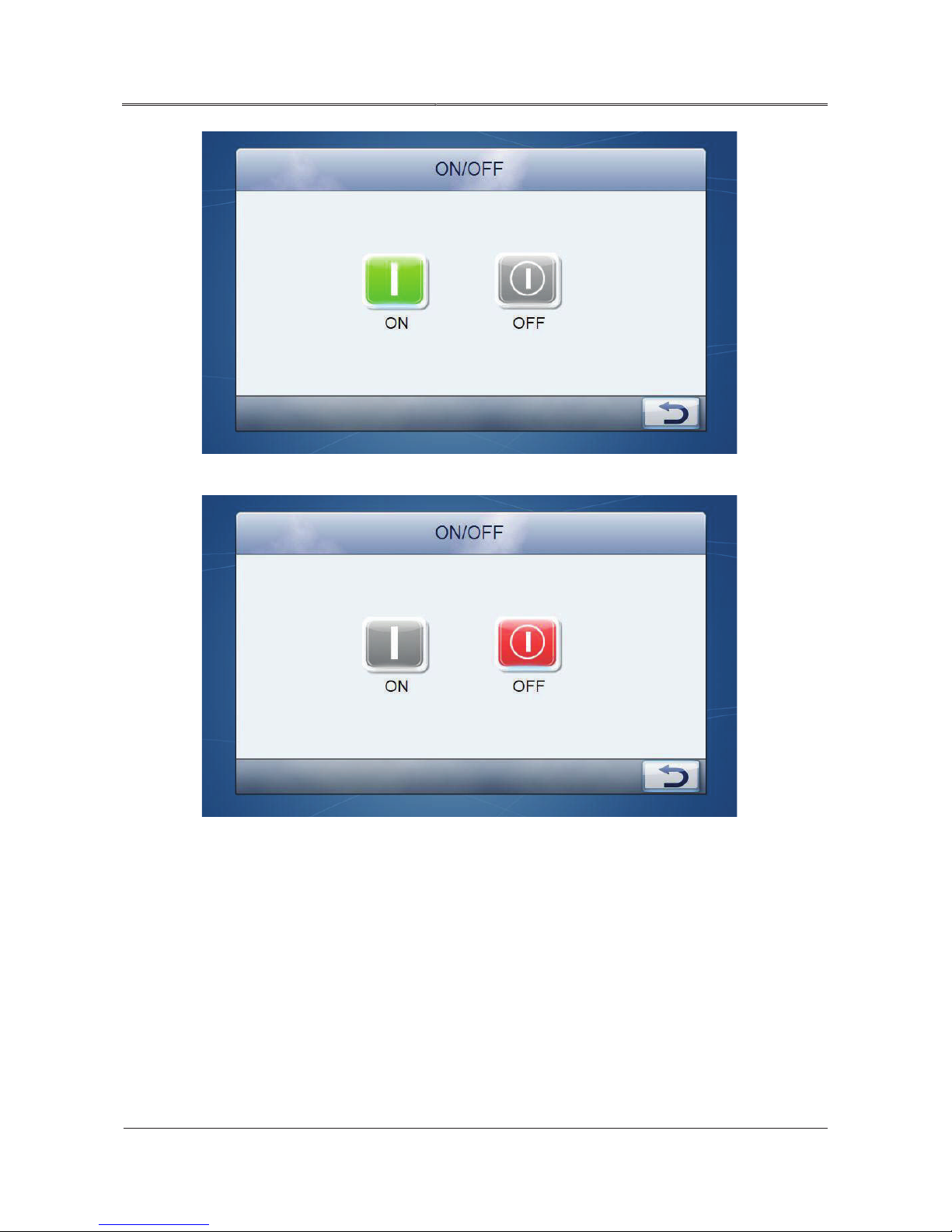
ON/OFF
On main page, click icon, it will enter on/off interface. When the system stay in starting status,
the ON button cannot be operated. As shown in Figure4-18, Figure4-19.
Page 52
44
All rights reserved ©N1 Critical Technologies, Inc.
NE Series (20-30kVA)
User Manual
Chapter 4 Operation Guide
Figure4-18 On/off interface 1
Figure4-19 On/off interface 2
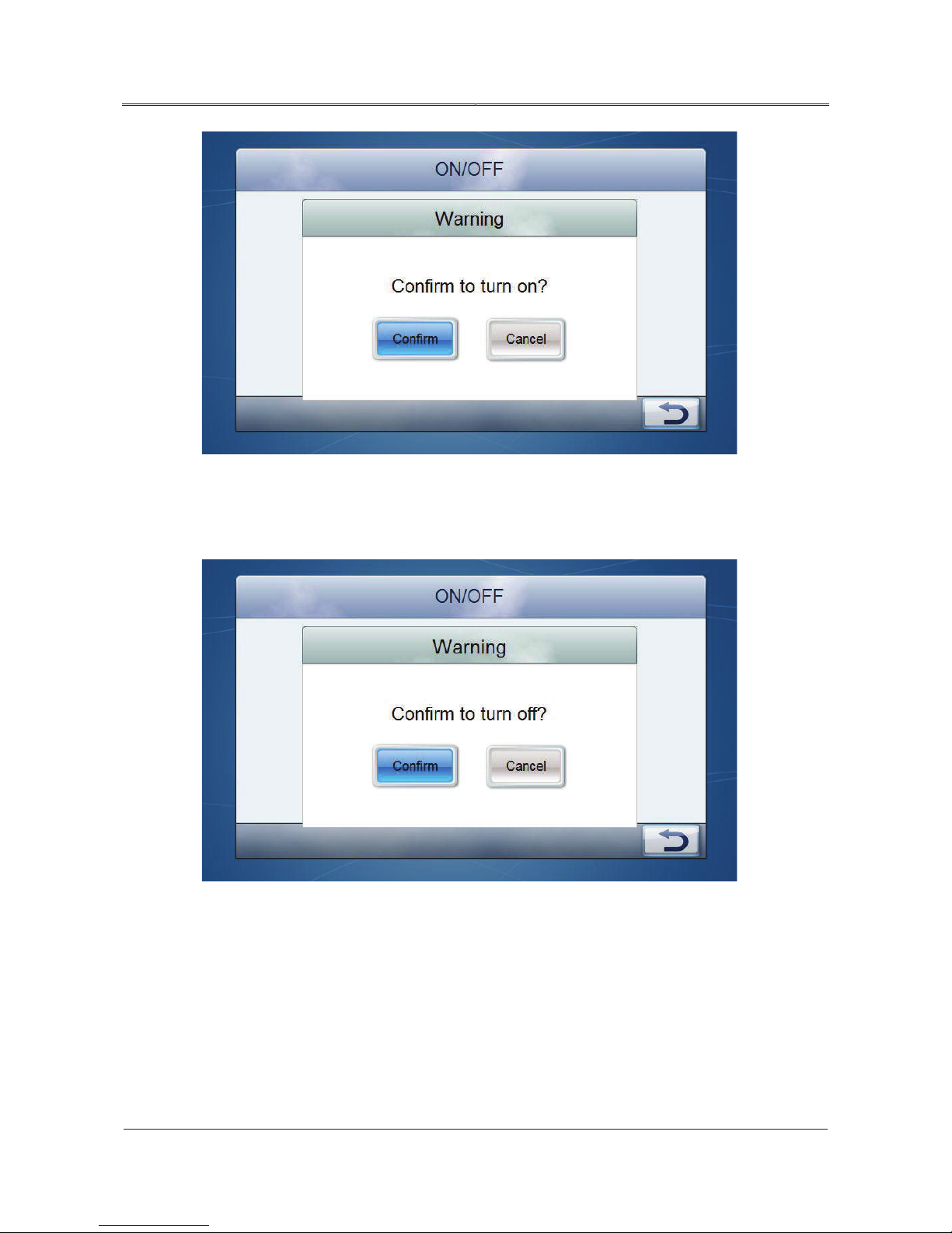
Click “ON” button, it will enter confirmation interface, click “Confirm” to perform startup operation.
Page 53
45
All rights reserved ©N1 Critical Technologies, Inc.
NE Series (20-30kVA)
User Manual
Chapter 4 Operation Guide
Figure4-20 Confirm to turn on
When closing, click OFF button, it will enter confirmation interface, click “Confirm” to perform
shutdown operation.
Figure4-21 Confirm to turn off
Page 54
46
All rights reserved ©N1 Critical Technologies, Inc.
NE Series (20-30kVA)
User Manual
Chapter 4 Operation Guide
Silence buzzer
When module or system occurs abnormal status, the buzzer will beep to alarm, and the buzzer indicator
on the top right corner of main page show as
normal, the icon will disappear. Click
closed, if there is new fault, the buzzer will start again.
4.6.5 Monitoring Function
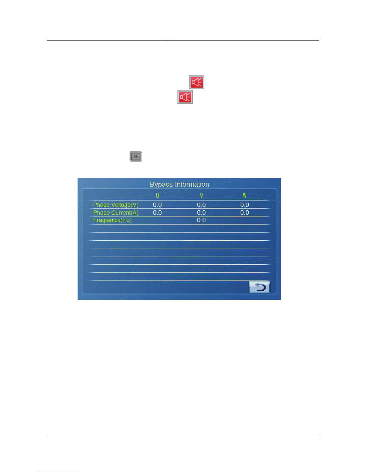
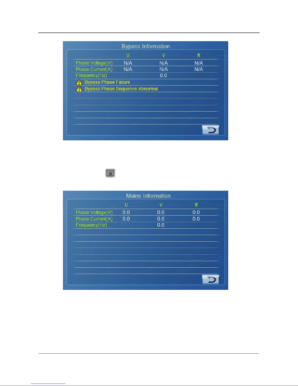
Bypass information
On main page, click icon, it will enter Bypass Information page, as shown in Figure4-22. The
page displays the phase voltage, phase current and frequency of current system input bypass.
and flicker. If the system recovers to
icon to close/ open the buzzer. When the buzzer is
Figure4-22 Bypass information
If the bypass loss phase or phase sequence abnormal, the data shows as “N/A” , and prompts related
abnormal information. When bypass power down, the frequency will show “ N/A” . As shown in
Figure4-23.
Page 55
47
All rights reserved ©N1 Critical Technologies, Inc.
NE Series (20-30kVA)
User Manual
Chapter 4 Operation Guide
Figure4-23 Bypass information (bypass abnormal)
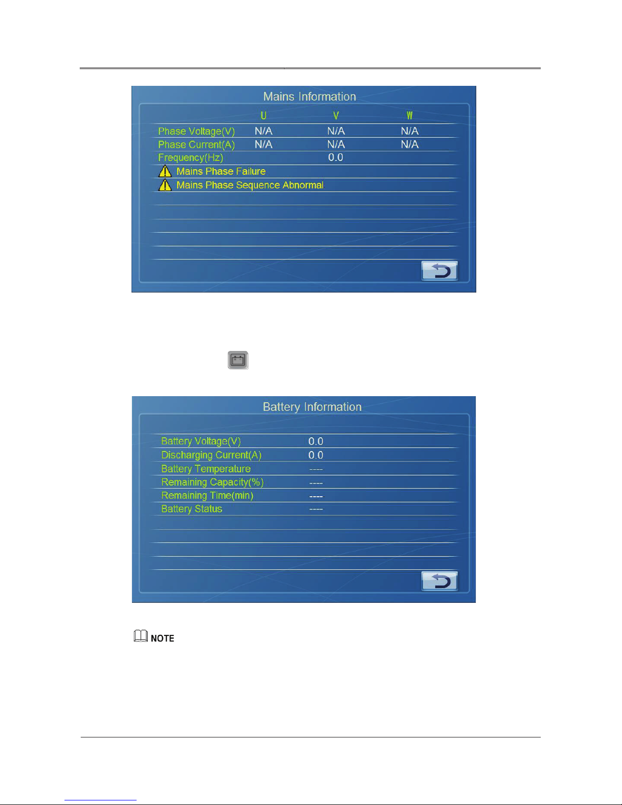
Mains information
On main page, click icon, it will enter Mains Information interface, as shown in Figure4-24.
The page displays the phase voltage, phase current and frequency of current system input mains.
Figure4-24 Mains information
If the mains lose phase or phase sequence abnormal, the data shows as “N/A” , and prompts related
abnormal information. When mains power down, the frequency will show “ N/A” . As shown in
Figure4-25.
Page 56
48
All rights reserved ©N1 Critical Technologies, Inc.
NE Series (20-30kVA)
User Manual
Chapter 4 Operation Guide
Figure4-25 Mains information (mains abnormal)
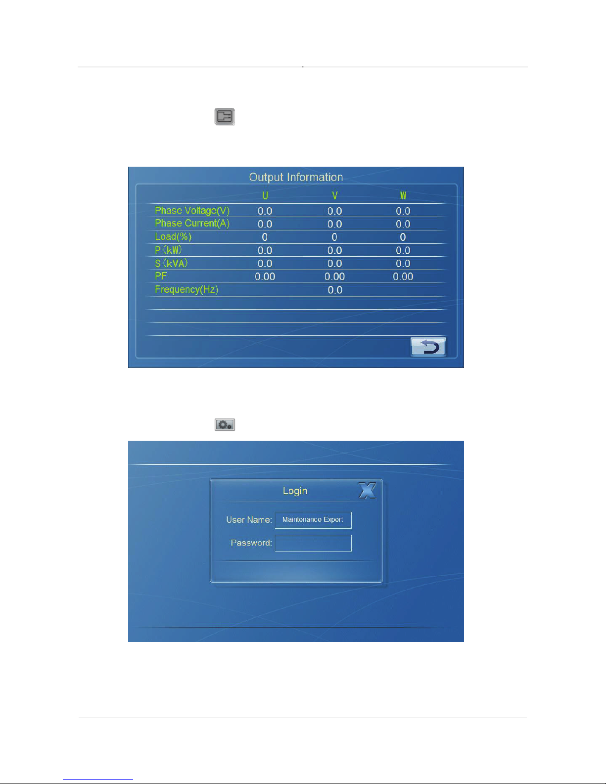
Battery information
On main page, click icon, it will enter Battery Information interface, the displayed
information is as shown in Figure4-26.
Figure4-26 Battery information
If the battery is not connected, battery status, battery temperature, remaining capacity, remaining time
will show as “----”.
System will display the charging current/discharging current according to battery status automatically.
Page 57
49
All rights reserved ©N1 Critical Technologies, Inc.
NE Series (20-30kVA)
User Manual
Chapter 4 Operation Guide
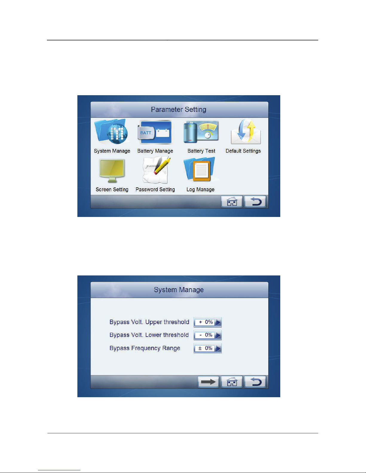
Output information
On main page, click icon, it will enter output information interface, as shown in Figure4-27.
The page displays the phase voltage, phase current, frequency, apparent power, active power and load
percentage.
Figure4-27 System output information
4.6.6 Parameters Setting
On main page, click icon, it will enter Login interface, as shown in Figure4-28.
Figure4-28 Login interface
Page 58
50
All rights reserved ©N1 Critical Technologies, Inc.
NE Series (20-30kVA)
User Manual
Chapter 4 Operation Guide
After entering right password (for general user, the initial password is: 111; for maintenance expert,
the password is: 222), it will turn to Parameter Setting page, as shown in Figure4-29. General user
can look up each system parameter with no setting rights. Maintenance expert can look up and set each
parameter.
Figure4-29 Parameter setting interface
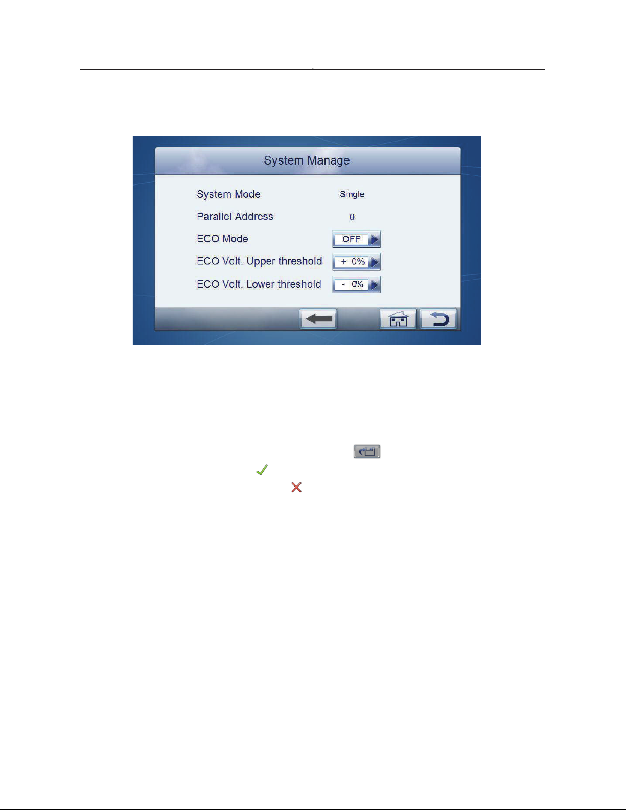
System Management
On Parameter Setting page, click system manage icon to enter System Manage interface, specific
parameters as shown in Figure4-30, Figure4-31. Click pulldown menu to change parameters.
Figure4-30 System management page 1
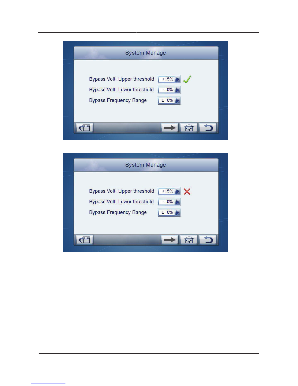
The setting range of bypass voltage upper threshold is +15%, +20%;
Page 59
51
All rights reserved ©N1 Critical Technologies, Inc.
NE Series (20-30kVA)
User Manual
Chapter 4 Operation Guide
The setting range of bypass voltage lower threshold is -15%, -20%, -25%;
The range of bypass frequency is:±5%, ±10%.
Figure4-31 System management page 2
ECO mode: on, off;
ECO voltage upper threshold: +10%, +15%;
ECO voltage lower threshold: -10%, -15%.
After changing the parameter, it is necessary to click
is successful, there will be a
setting is unsuccessful, there will be a
icon at the right side of the parameter, as shown in Figure4-32, if
icon at the right side of the parameter, as shown in
Figure4-33.
button to save the setting. If the setting
Page 60
52
All rights reserved ©N1 Critical Technologies, Inc.
NE Series (20-30kVA)
User Manual
Chapter 4 Operation Guide
Figure4-32 Successful setting
Figure4-33 Unsuccessful setting
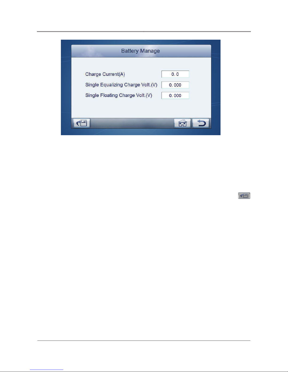
Battery management
On parameters setting page, click “Battery Manage” icon, it will enter battery manage page, as shown
in Figure4-34.
Page 61
53
All rights reserved ©N1 Critical Technologies, Inc.
NE Series (20-30kVA)
User Manual
Chapter 4 Operation Guide
Figure4-34 Battery management
Charge current range.
Single equalizing charge voltage range.
Single floating charge voltage range.
Click number input box, it will display the input range of setting value at the top of the input
Battery test
keyboard, when the setting exceeds the range, the setting will be invalid. After setting, click
button to save the setting. Successful setting/ unsuccessful setting identification is the same as that of
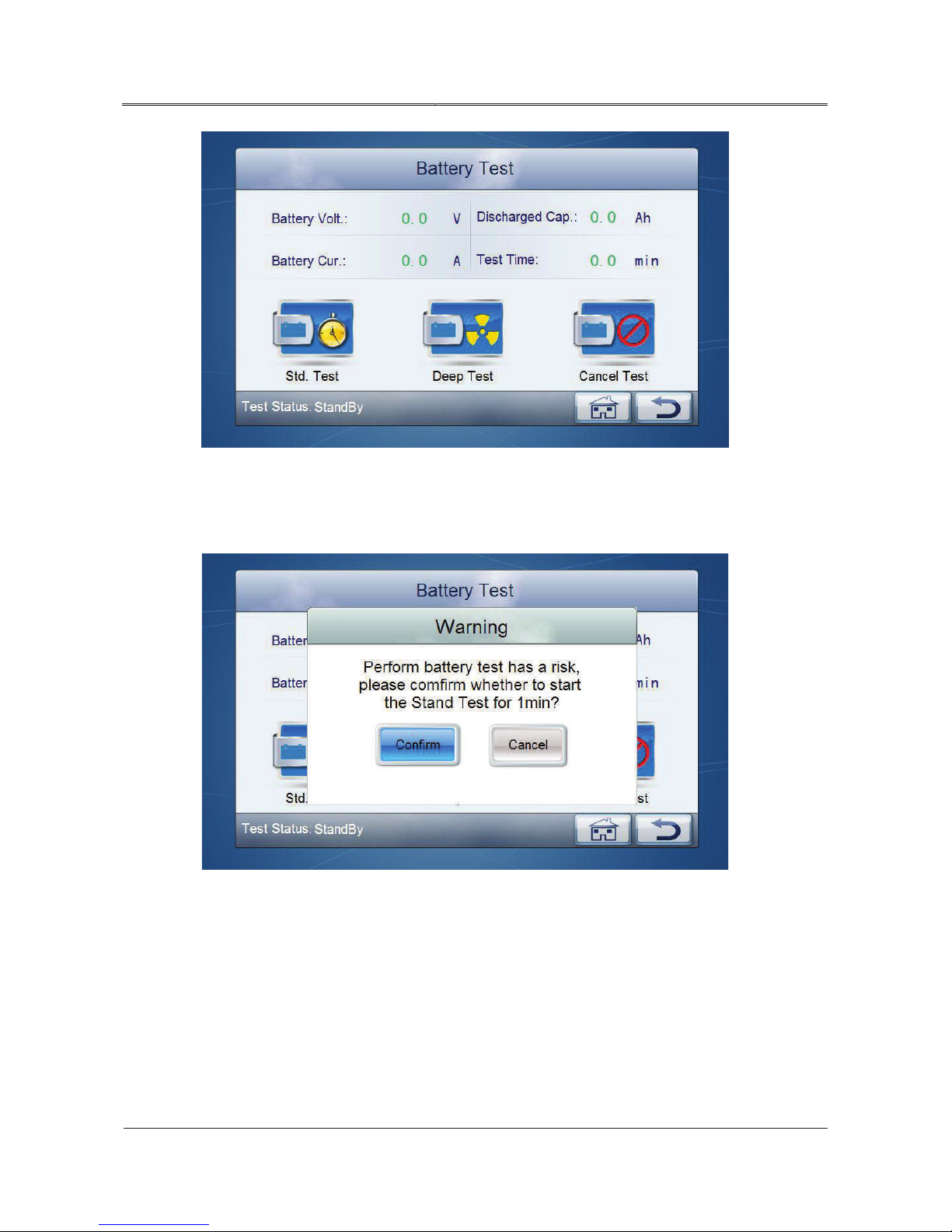
system management.
On Parameter Setting page, click “battery test” icon to enter battery test page, as shown in Figure4-
35.
Page 62
54
All rights reserved ©N1 Critical Technologies, Inc.
NE Series (20-30kVA)
User Manual
Chapter 4 Operation Guide
Figure4-35 Battery test page
Click “Std. Test” icon, it will popup confirming window, click “confirm” to start standard test, as
shown in Figure4-36.
Figure4-36 Standard test
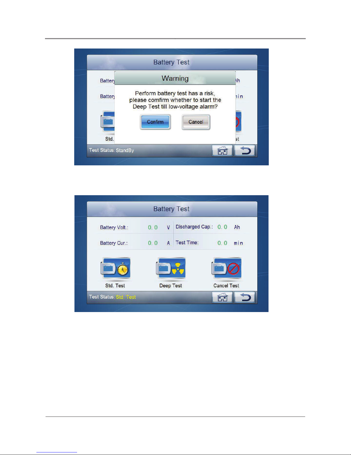
Click “Deep Test” icon, it will popup confirming window, click “confirm” to start deep test, as shown
in Figure4-37.
Page 63
55
All rights reserved ©N1 Critical Technologies, Inc.
NE Series (20-30kVA)
User Manual
Chapter 4 Operation Guide
Figure4-37 Deep test
After starting battery test, the test status will show “std. test” / “deep test”, as shown in Figure4-38.
Figure4-38 Battery test
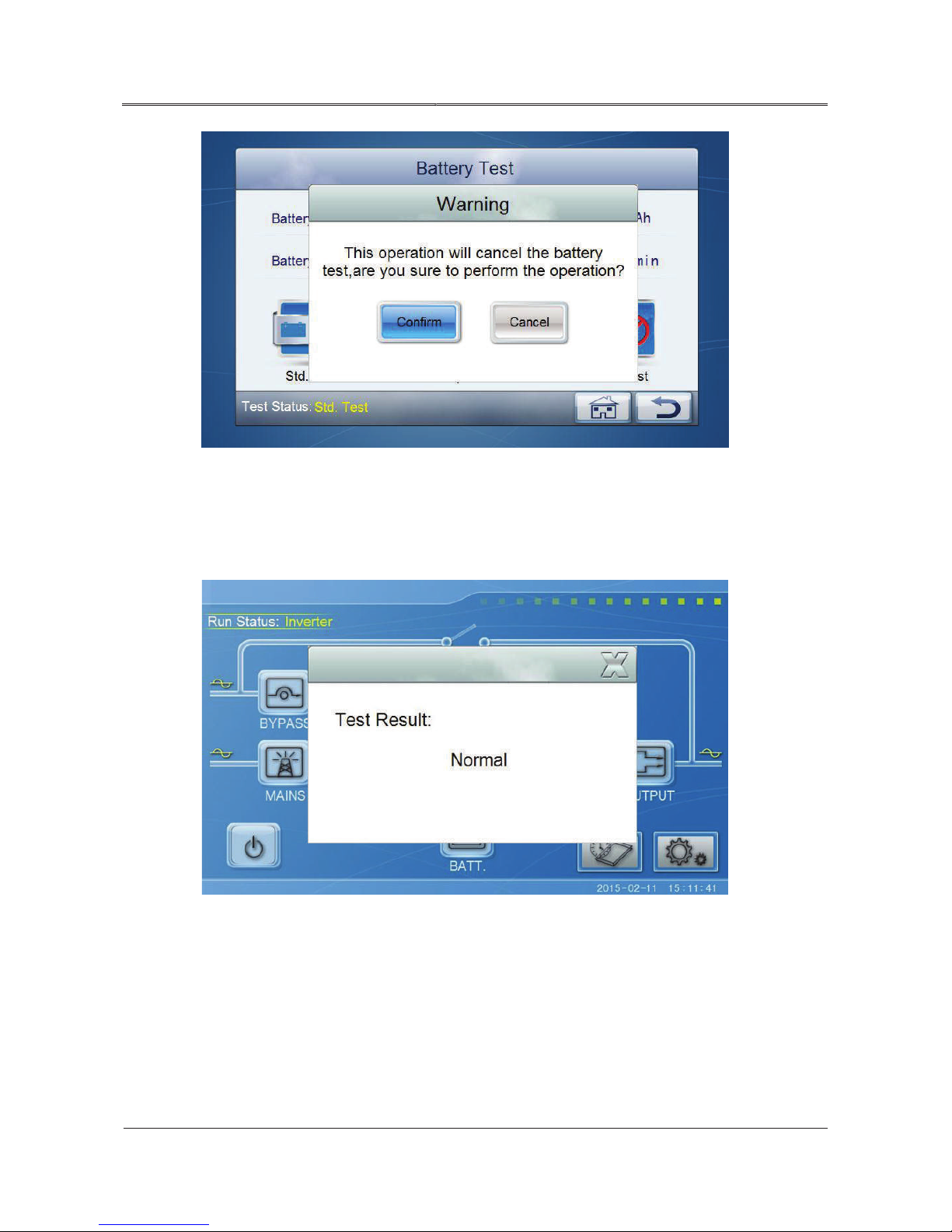
During battery testing, if it needs to stop testing, you can enter Battery Test page, click “cancel”
button to cancel battery test, as shown in Figure4-39.
Page 64
56
All rights reserved ©N1 Critical Technologies, Inc.
NE Series (20-30kVA)
User Manual
Chapter 4 Operation Guide
Figure4-39 Cancel battery test
After finishing the battery test, it will popup the battery test result, as shown in Figure4-40, Figure4-
41, Figure4-42. Figure4-43 shows the prompting window for abnormally exiting when battery test
condition is not satisfied.
Figure4-40 Battery test result: normal
Page 65

57
All rights reserved ©N1 Critical Technologies, Inc.
NE Series (20-30kVA)
User Manual
Chapter 4 Operation Guide
Figure4-41 Battery test result: battery capacity low
Figure4-42 Battery test result: please check battery
Page 66
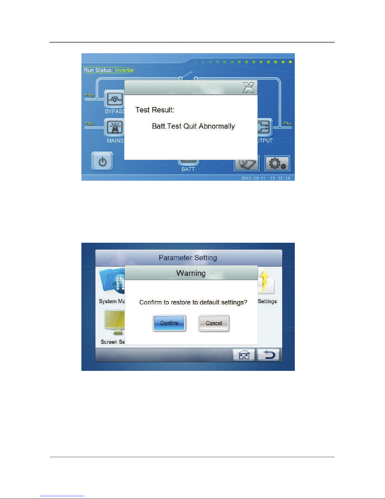
58
All rights reserved ©N1 Critical Technologies, Inc.
NE Series (20-30kVA)
User Manual
Chapter 4 Operation Guide
Figure4-43 Abnormal quit for not satisfy battery test condition
Restore factory settings
On Parameter Setting page, click “default setting” icon, it will popup confirmation window, as
shown in Figure4-44.
Figure4-44 Restore to default setting
After clicking “Confirm” button, if the setting is successful, it will popup the prompting window as
shown in Figure4-45, if the setting is unsuccessful, it will popup the prompting window as shown in
Figure4-46.
Page 67
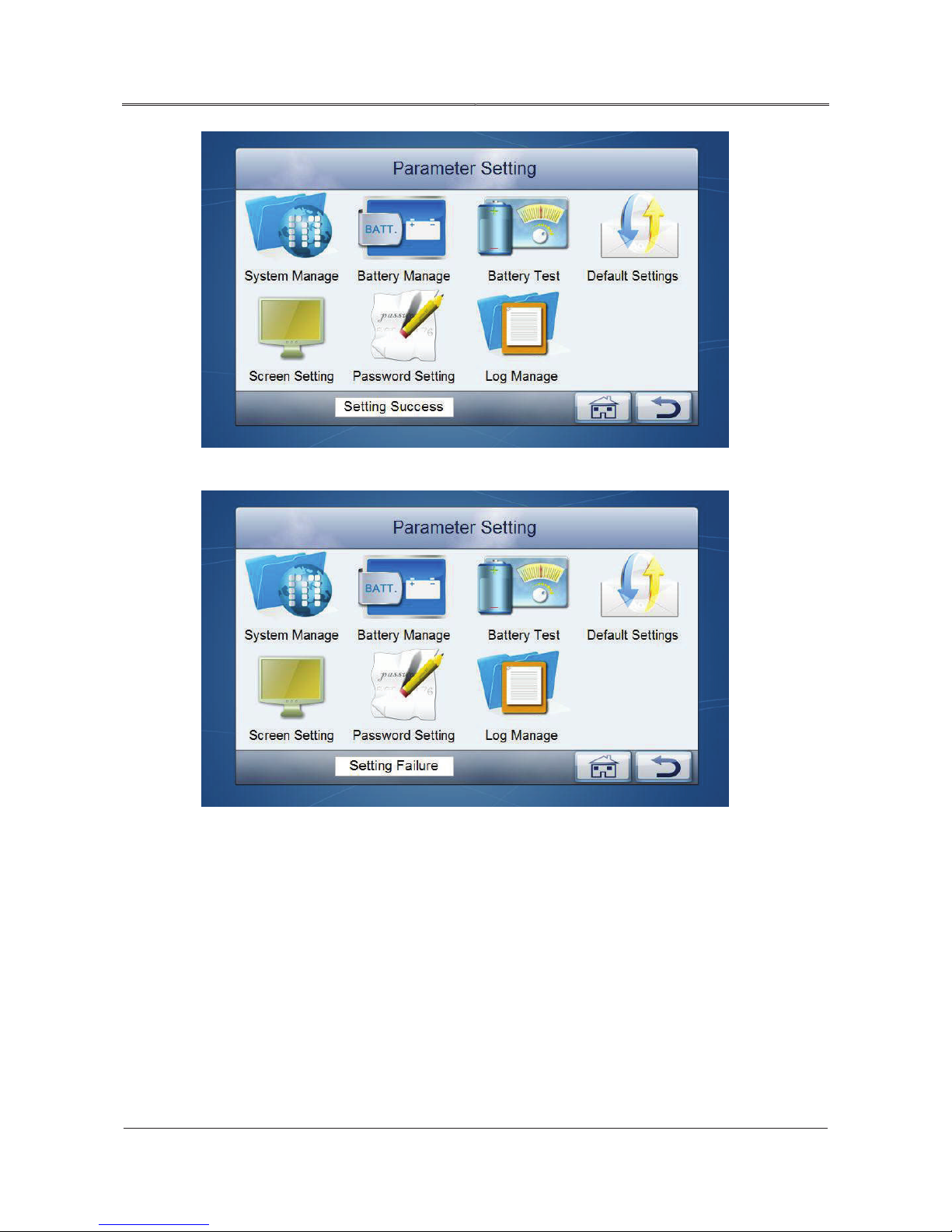
59
All rights reserved ©N1 Critical Technologies, Inc.
NE Series (20-30kVA)
User Manual
Chapter 4 Operation Guide
Figure4-45 Setting success prompting window
Figure4-46 Setting failure prompting window
Screen setting
On Parameter Setting page, click “screen setting” icon, it will enter Screen Setting interface, as
shown in Figure4-47.
Page 68
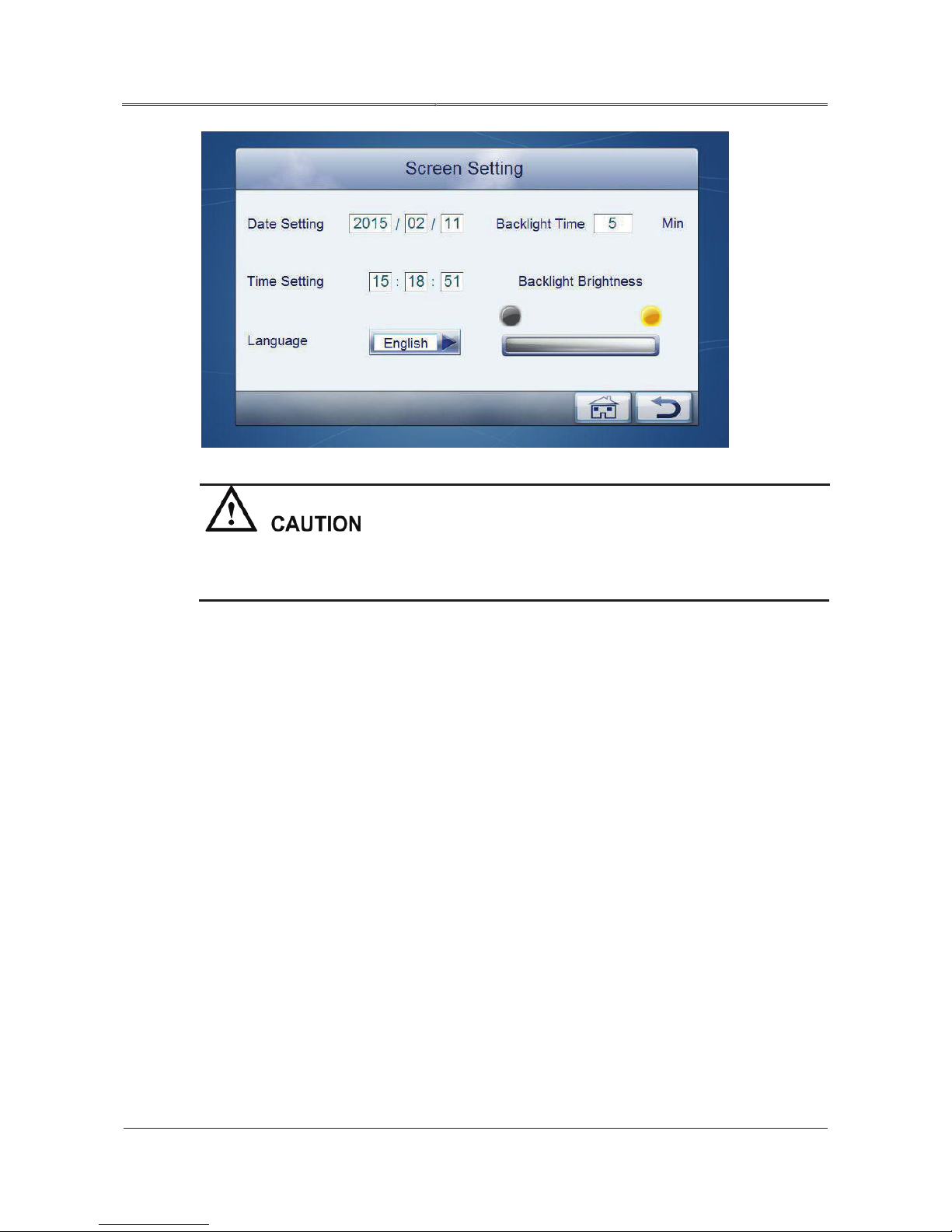
60
All rights reserved ©N1 Critical Technologies, Inc.
NE Series (20-30kVA)
User Manual
Chapter 4 Operation Guide
Figure4-47 Screen setting
When setting system time, it is necessary to keep the system time and actual time the same,
which is good for the veracity of event records and mastering the status of system accurately.
Password setting
On Parameter Setting page, click “password setting” icon, it will enter Password Setting page. The
current user’s password can be changed only, as shown in Figure4-48. The password is 1 to 6 positions
Arabic numerals. After filling in new password, click “confirm” button to save the setting.
Remember your password. There is no master password that will let you reset any forgotten
passwords and the manufacturer cannot help you if your password information is lost or
forgotten.
Page 69
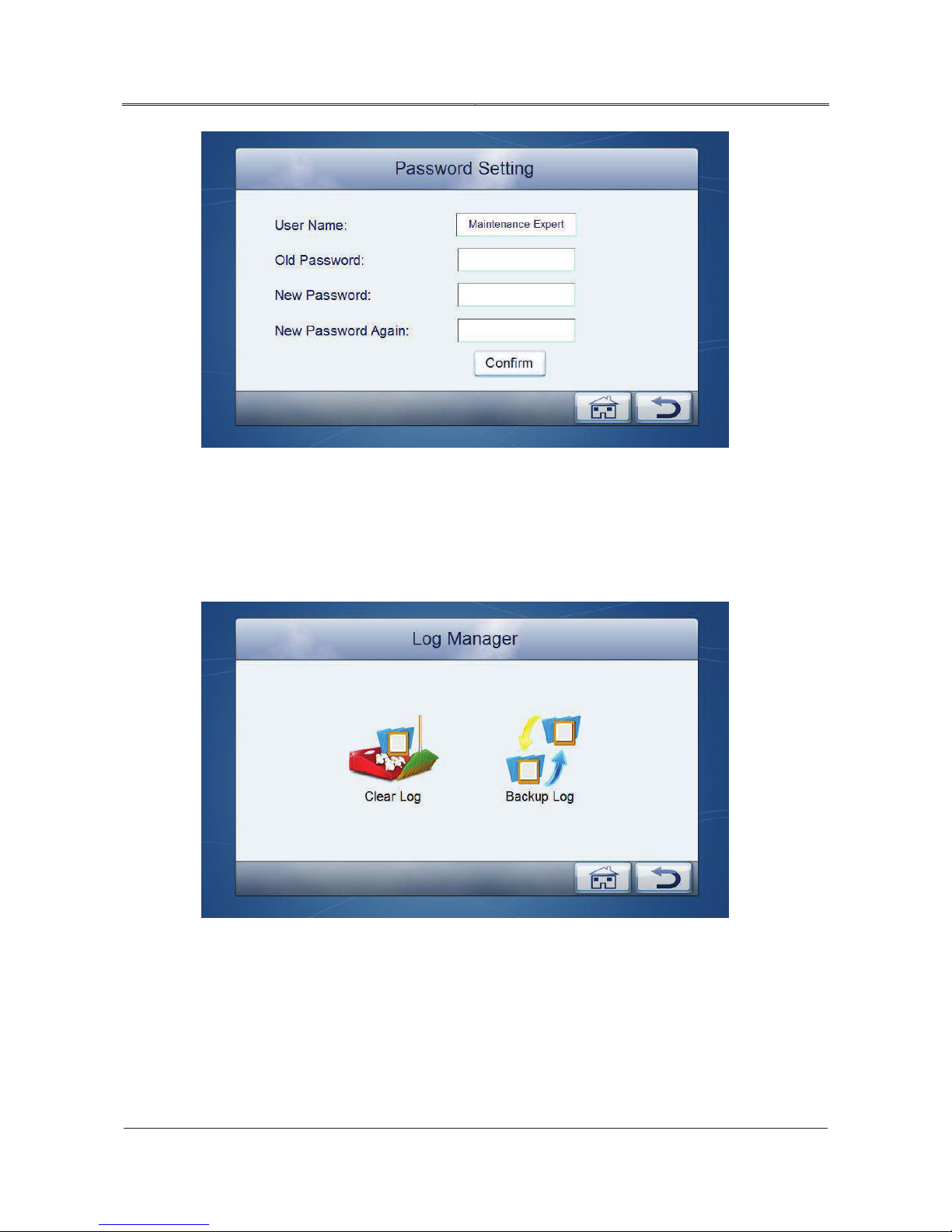
61
All rights reserved ©N1 Critical Technologies, Inc.
NE Series (20-30kVA)
User Manual
Chapter 4 Operation Guide
Figure4-48 Password setting
Log manager
On Parameter Setting page, click “log manager” icon, it will enter Log Manager page. On the page,
you can clear log and user log. Insert U dish, and then you can backup the records. As follows.
Figure4-49 Log manager
Page 70
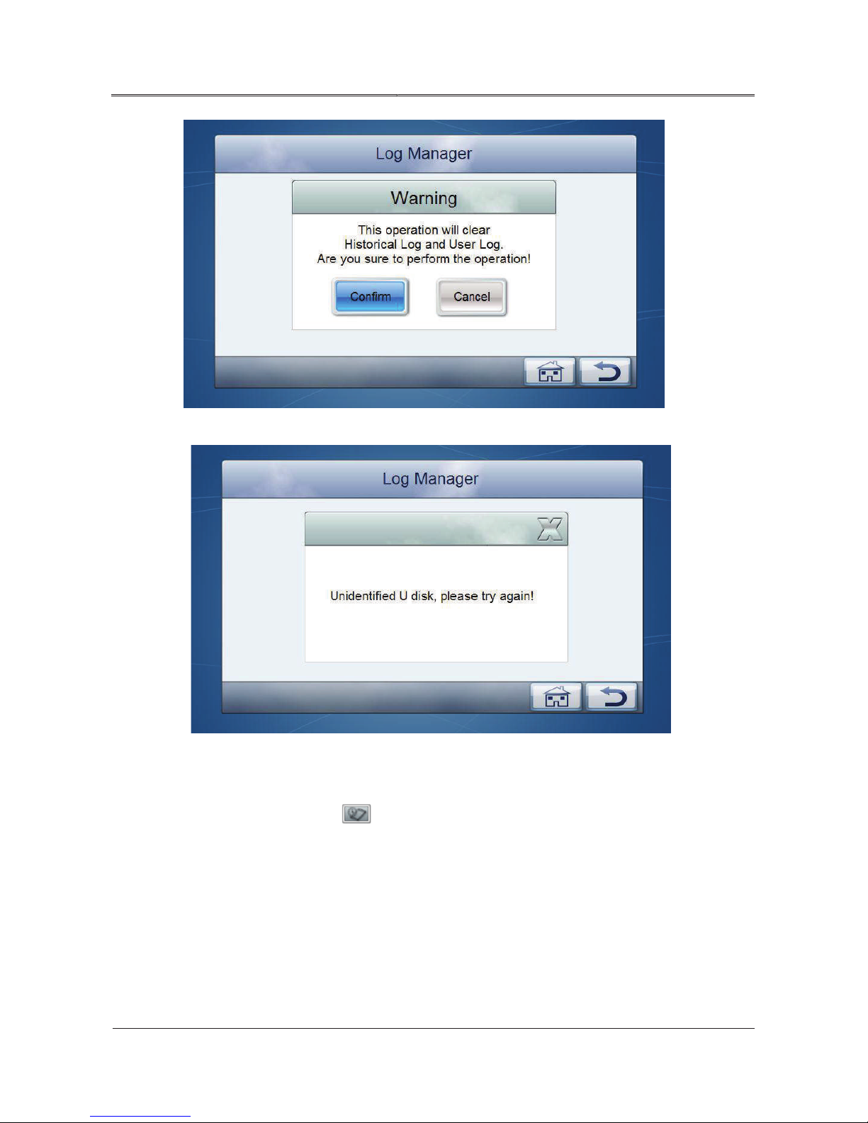
62
All rights reserved ©N1 Critical Technologies, Inc.
NE Series (20-30kVA)
User Manual
Chapter 4 Operation Guide
Figure4-50 Prompt for clearing log
Figure4-51 The U dish is not inserted
4.6.7 Information Inquiry
On monitoring page, click icon to enter Information Inquiry page, the related information is
as shown in Figure4-52.
Page 71
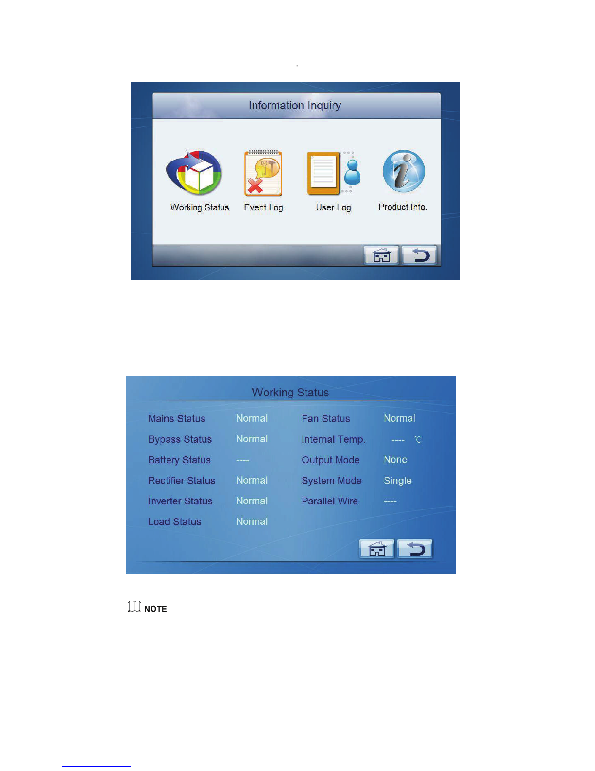
63
All rights reserved ©N1 Critical Technologies, Inc.
NE Series (20-30kVA)
User Manual
Chapter 4 Operation Guide
Figure4-52 Information inquiry
Work status
On Information Inquiry page, click “working status” icon, it will enter Work Status page, as
shown in Figure4-53.
Figure4-53 Work status
If the battery is not connected, battery status will show as “----”; when the work mode is single mode,
the parallel wire status will show as “--”.
Page 72
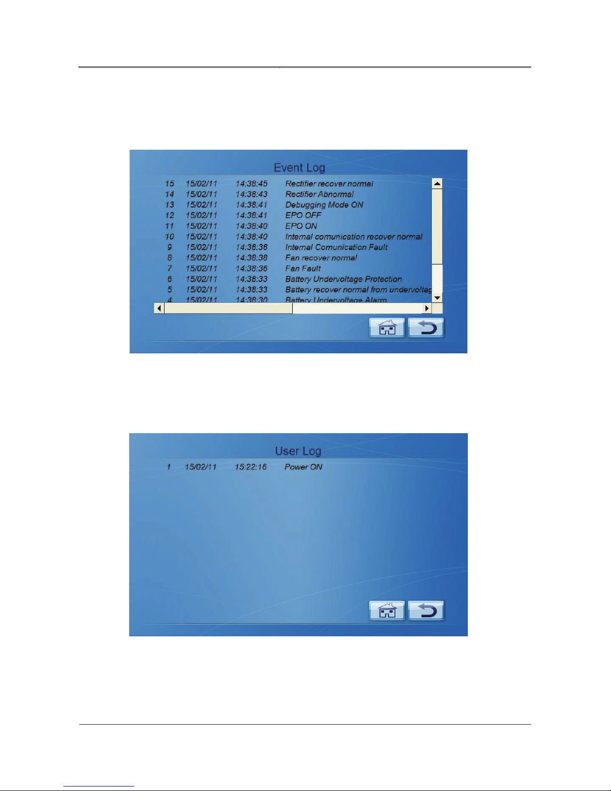
64
All rights reserved ©N1 Critical Technologies, Inc.
NE Series (20-30kVA)
User Manual
Chapter 4 Operation Guide
Event log
On Information Inquiry page, click “event log” icon, it will enter Event Log page. The page
records the historical fault and alarm information of the system, as shown in Figure4-54.
Figure4-54 Event log
User log
On information inquiry page, click “user log”, it will enter User Log page, as shown in Figure4-55.
Figure4-55 User log
Page 73
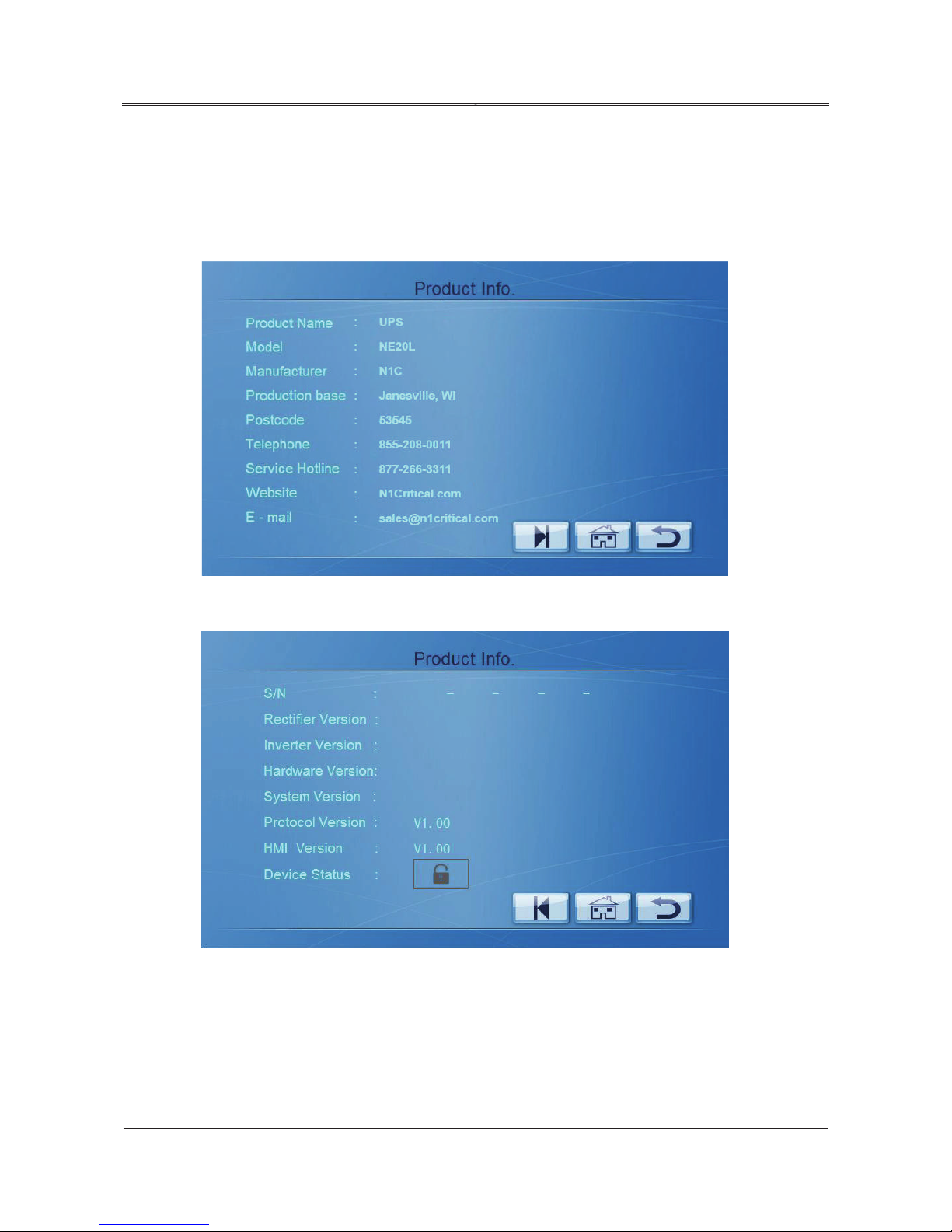
65
All rights reserved ©N1 Critical Technologies, Inc.
NE Series (20-30kVA)
User Manual
Chapter 4 Operation Guide
Product information
On Information Inquiry page, click “product info.” Icon, it will enter Product Info. page, the first
page shows the product name, model, manufacturer, contact information, etc. as shown in Figure4-56.
Figure4-56 Product information page 1
The second page shows product version information and device status, as shown in Figure4-57
Figure4-57 Product information page 2
Page 74

66
All rights reserved ©N1 Critical Technologies, Inc.
NE Series (20-30kVA)
User Manual
Chapter 4 Operation Guide
When the probation is opened, the device status shows as . At this time, user can click
icon to enter probation unlock page. After successful unlock, the device status will show as
.
Page 75

67
All rights reserved ©N1 Critical Technologies, Inc.
NE Series (20-30kVA)
User Manual
Chapter 5 Maintenance Guide
Chapter 5 Maintenance Guide
This chapter introduces the maintenance of UPS, including safety precautions, periodic preventative
maintenance, battery maintenance, fan maintenance and so on. Proper maintenance is the key to enable
the device run in the best status and with a longer service life.
5.1 Safety Precaution
Pay attention to the following safety operation regulations:
Remember that there always exists hazardous voltage inside UPS even when UPS does not run.
Before maintaining the UPS, use a multimeter to check the voltage and make sure that the UPS is
completely closed.
Before operating the UPS, remove rings, necklaces, watches or other conductive metal
ornaments. Do not wear loose clothing.
Operate it in strict accordance with safety procedures. If in doubt, please consult a certified
electrical technician to maintain your equipment.
The UPS has the function of battery polarity detecting. If the switch of external battery is closed
or battery polarity detection LED is on, that means the battery polarity is reverse connected, it is
necessary to disconnect the external battery switch and adjust the battery wiring.
Keep environment clean to avoid dust or chemical contamination pollution to UPS.
5.2 Periodic Preventative Maintenance
To improve the efficiency and reliability of the UPS system, please complete the following
preventative maintenance operations (every 3 months):
Examine the input and output terminals termly to ensure the good contact.
Examine fans working status termly to prevent sundries from plugging up the ventilation. If any
damage, please replace it at the time.
Page 76

68
All rights reserved ©N1 Critical Technologies, Inc.
NE Series (20-30kVA)
User Manual
Chapter 5 Maintenance Guide
Examine the batteries voltage termly to make sure that the voltage of the battery is normal.
Examine the system running status termly to find the failure in time.
5.3 Battery Maintenance
5.3.1
Precaution for Battery Charging
When cleaning battery case, use a damp (water) cloth. Do NOT use oil substance or organic,
flammable solvents such as gasoline or thinner. Do not touch the battery terminals with the
cleaning cloth.
Battery should be kept away from fire as well as all electrical equipment which may easily cause
spark to avoid explosion.
To prevent batteries from starting a fire, do not short-circuit battery terminals.
Battery electrolytes irritate skin. To avoid electrolyte leakage, do not open battery covers.
5.3.2 Battery Maintenance
To ensure a long battery lifespan, perform the following maintenance tasks periodically.
Normally it needs to charge and discharge the battery once every 4~6 months, and charging time
should not be less than 24h every time.
In high temperature area, the battery should be charged and discharged once every two months,
and charging time should be not less than 24h every time.
If battery hasn’t been used for a long time, it should be charged and discharged every three
months, and charging time should not be less than 24h.
Do not over-discharge batteries. After batteries stop discharging, fully charge them within 24
hours.
After using for six months, check that whether battery cables are properly connected.
If the UPS is not used, please disconnect the battery switch on the UPS to avoid long-time
discharge after mains failure.
5.3.3 Battery Replacement
Observe the following precautions when replacing a battery:
Consult professional technicians for replacing batteries.
Page 77

69
All rights reserved ©N1 Critical Technologies, Inc.
NE Series (20-30kVA)
User Manual
Chapter 5 Maintenance Guide
Replace the used battery with new ones that are in the same capacity, same type and same
manufacturer. It is strictly prohibited to use the battery with different capacity, type and
manufacturers.
Batteries that are replaced should be recycled.
5.4 Fan Maintenance
Check periodically that whether fans work properly and make sure air vents are not blocked. If a fan
stops running, maintain or replace it promptly.
Page 78

70
All rights reserved ©N1 Critical Technologies, Inc.
NE Series (20-30kVA)
User Manual
Chapter 6 Troubleshooting
Chapter 6 Troubleshooting
This chapter introduces the troubleshooting of UPS, including identifying the UPS Status, UPS
emergency troubleshooting measures and so on.
6.1 Judge the UPS Status
Table6-1 Common abnormal problems diagnosis
NO. Phenomena Fault diagnosis and checking points Solution
AC/DC green
indicator on panel
1
is off.
The touch screen
displays wrong
phase sequence, the
2
buzzer beeps
continuously.
The inverter cannot
output normally,
3
and the buzzer
beeps continuously.
When mains power
outage, the UPS
4
halts with no
output.
Check if the mains switch is on and if the
fuse is OK.
Check if the mains input voltage is
during the rated range.
AC input phase is wrong
The rectifier is not completely started;
the buzzer beeps continuously and
battery low-voltage indicator is on;
battery input switch is not closed.
Output is overload; the LOAD overload
indicator on the panel is on.
Battery input switch is not opened;
check if battery return circuit alarms
abnormally.
——
——
Change the phase
sequence of rectifier’s
mains input wires.
Generally, it only needs
to change two phases
among L1, L2, L3.
Please wait that
rectifier finishes
starting and the buzzer
relieves long beep.
Decrease the load.
Close the battery
switch.
Page 79

71
All rights reserved ©N1 Critical Technologies, Inc.
NE Series (20-30kVA)
User Manual
Chapter 6 Troubleshooting
NO. Phenomena Fault diagnosis and checking points Solution
The touch screen
5
and LED are off.
The red DC/AC
indicator is on, and
6
the buzzer beeps
continuously.
LOAD indicator is
7
on.
When power on
8
normally, it cannot
output normally.
Check if the bypass/ mains switch is
Please inform
professionals to
closed and the power board is fault.
maintain.
Get rid of the
short-circuit point,
Check if the load is short-circuit.
close the inverter, and
then restart the inverter.
Check if the fuse of inverter is fusing or
IGBT module is abnormal.
Check if the input mains is power
down, and the battery is under
low-voltage protection.
Replace the fuse or
IGBT module
It will start
automatically if the
mains normal.
The output of UPS is overload. Decrease the load.
Please inform
Check whether the bypass/inverter SCR
professionals to
drive board is fault.
maintain
The insert position of communication
wire is not proper.
The communication software is not
Communication
successful installed.
9
abnormal
The setting for computer’s
communication window is wrong.
Above problems are all eliminated, but
it still cannot normally communicate.
6.2 Deal with Common Faults
When starting the UPS, if the UPS cannot work normally, please refer to Table6-2 to look for reasons.
At the same time, please check if it is caused by environmental factors, such as temperature, humidity
not meeting the system’s requirements.
Insert the
communication wire
properly.
Install the software
correctly.
Properly set the
communication port.
Please inform
professionals to
maintain.
Page 80

72
All rights reserved ©N1 Critical Technologies, Inc.
NE Series (20-30kVA)
User Manual
Chapter 6 Troubleshooting
Table6-2 only contains some simple troubleshooting. It the answer for diagnosis is not clear or not
After starting, the UPS can
normal, but once starting the
the result of short circuit. Common reason is that
→
load → small power load” after UPS running stably.
sufficient, please contact N1 Critical Technologies.
Table6-2 Troubleshooting
No. Phenomenon Possible reason
1 Mains is normal, but the UPS
works in battery inverting status,
buzzer beeps intermittently.
2 After installing, close switch or
power switch, the fuse will trip or
burn out.
3
output 110V AC power, but the
UPS works in bypass status.
4 After starting, the UPS output is
load, the UPS stops outputting
immediately.
The surfaced of a contact socket is bad, which leads to
AC input being blocked.
The input wires of UPS are wrongly connected, such as
the neutral wire and live wire or live wire and grounding
wire (cabinet) is reverse connected, or the three wires of
the output are wrongly connected.
The load capacity exceeds the rated output capacity. It
is necessary to decrease load or use a UPS with bigger
output capacity.
If it is a temporary bypass caused by starting the
load and can recover automatically, that is normal.
The UPS is overloaded or short-circuit of output return
circuit. Decrease the load to normal capacity or find out
output socket is short circuited.
The startup of load is not in the order of “big power
load
small power load”. It is necessary to restart the
UPS, and start the load in the order of “big power
Page 81

73
All rights reserved ©N1 Critical Technologies, Inc.
NE Series (20-30kVA)
User Manual
Chapter 6 Troubleshooting
No. Phenomenon Possible reason
After starting, the UPS works
the UPS shuts down
In the status of battery supply power, the battery is
protected for low-voltage caused by discharging, the
When mains normal, the UPS
outputs normally, when mains
failure, the UPS is without
5
normally, but some time later,
system shuts down automatically. The phenomenon is
automatically.
normal. Once the mains recover, the system will start
automatically and charge for the battery.
Warning: if the battery stays in low-voltage for a long
time, it will influence the life span of battery. After
low-voltage protection for battery, if the mains cannot
recover for long time, it is necessary to disconnect the
battery switch to protect the battery, and restart the
UPS when mains normal, and charge
for the battery.
6 After the UPS starts to work for a
while, the buzzer beeps
intermittently.
7
output.
8 The buzzer beeps continuously,
inverter fault and the UPS turn to
bypass status to supply power.
The voltage of grid is too low, and the UPS works in
battery inverting status, finally, it put the battery into
low-voltage protection.
Battery fault or the battery group is damaged.
Charger fault. The charging for battery fails, leading to
no battery power capability.
Battery wire connection is bad or the connection of
terminal is bad.
The battery switch is not closed.
After serious overload, the UPS is not restarted,
which causes the UPS always stay in bypass output
status.
Overload or output is short-circuiting, the UPS shuts
down to protect automatically.
Drive or power tube is fault.
Main controlling board is fault.
DC fuse is open-circuit.
Page 82

74
All rights reserved ©N1 Critical Technologies, Inc.
NE Series (20-30kVA)
User Manual
Chapter 6 Troubleshooting
No. Phenomenon Possible reason
Under mains status, the UPS
9 There is mains, but the buzzer
beeps intermittently, mains
indicator is off.
10
works normally; however, after
power outage, the UPS work
normally but the device stops.
11
All the indicators on the panel
of the UPS are not lit on.
6.3 Emergency Troubleshooting
Emergency for the fault of signal-unit
When the single-unit faults, it is necessary to close the power supply of UPS by OFF button on
the panel. If necessary, close the user load, and disconnect the input/output switch of UPS, which
is to avoid further damage of the UPS.
Voltage or frequency of mains exceeds the range of
UPS.
Bad grounding causes the float voltage between neutral
wire and grounding wire being too high.
The connection of display controlling board of the UPS
is bad or failure.
Emergency for the fault of UPS 1 and UPS 2 in series backup system
When the UPS 1 of the series backup system fault, it is necessary to close the power supply of
UPS1 by OFF button on the panel. At the same time, disconnect the mains input switch and battery
switch of UPS 1 (UPS1 or battery cabinet). Inform the engineering technician to maintain.
When the UPS 2 fault, it is necessary to close the power supply of UPS2 by OFF button on the
panel. At the same time, disconnect the mains input switch and battery switch of UPS 2 (UPS2 or
battery cabinet). Inform the engineering technician to maintain.
Emergency for the fault of the single-unit in parallel system
When the single-unit in parallel system fault, it is necessary to close the power supply of UPS by
OFF button on the panel. Then disconnect the switch of AC input, output and battery (UPS 1or
battery cabinet). Inform the engineering technician to maintain.
Page 83
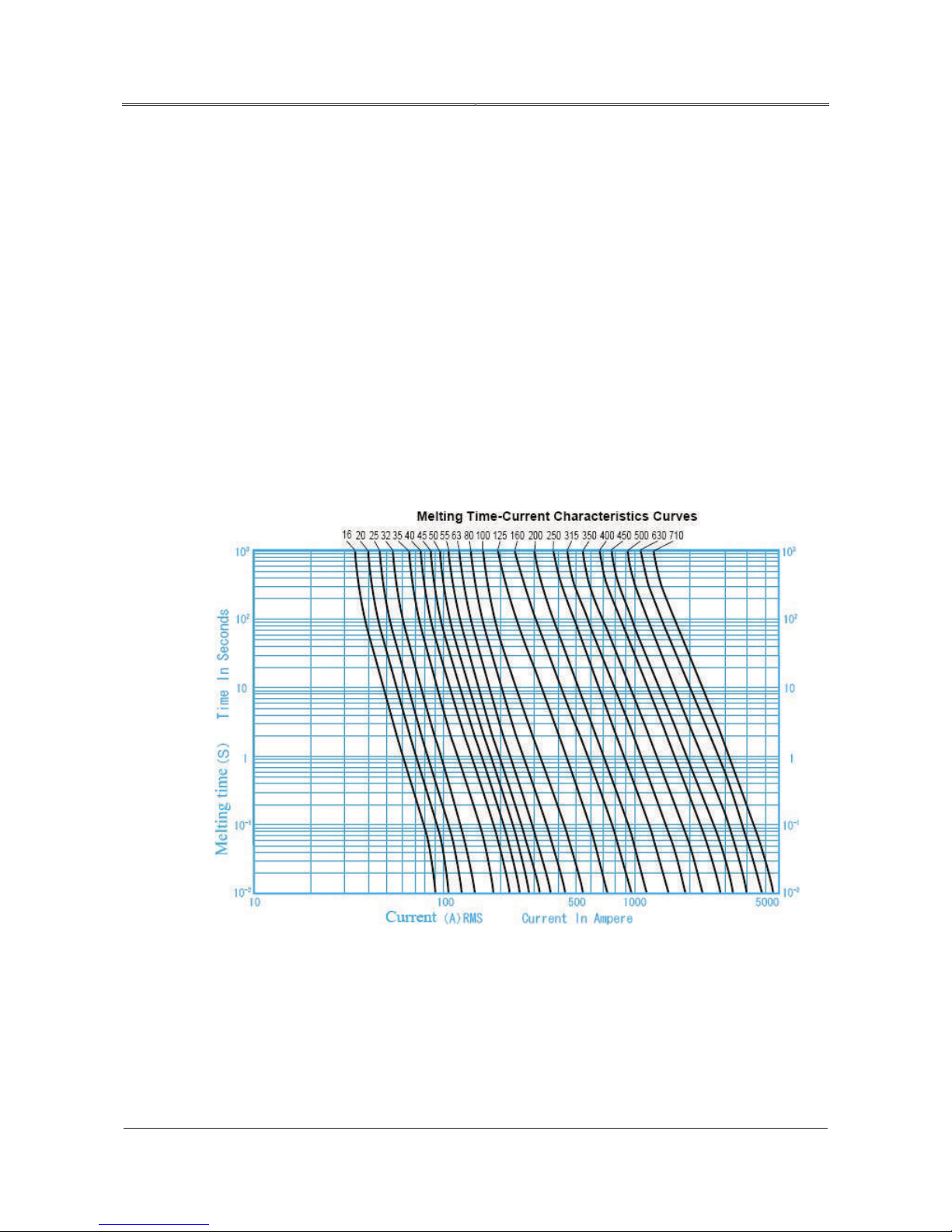
75
All rights reserved ©N1 Critical Technologies, Inc.
NE Series (20-30kVA)
User Manual
Chapter 6 Troubleshooting
6.4 Replace the Fuse
When there is something wrong with the device, the fuse can effectively protect the key components,
and separate the fault from the system to avoid the fault expanding. If the fuse is damaged, it is
necessary to replace the fuse that with the same type or passed the safety criterion and with the same
character on the basis of corresponding rules. The fuse fusing character and disjunction capacity of the
fuse used in input end, output end, battery input end of this series device are as follows:
Battery input: fuse 660GH/660V/315A, disjunction capacity: 100KA. The fusing characteristics are as
follows.
Mains input, bypass input, output: fuse 660GH/660V/400A, disjunction capacity: 100KA. The fusing
characteristics are as follows.
Charging end: fuse 660GH/660V/100A; disjunction capacity: 100KA. The fusing characteristics are as
follows.
Figure6-1 Fuse characters of fuse 660GH
Page 84
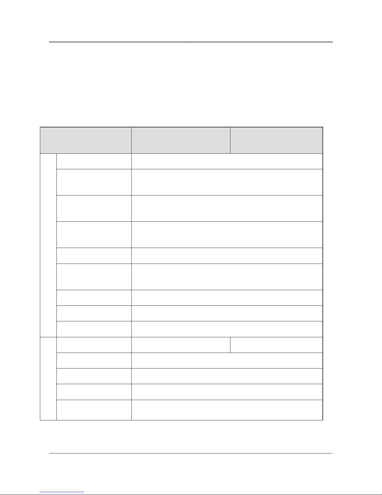
76
All rights reserved ©N1 Critical Technologies, Inc.
NE Series (20-30kVA)
User Manual
A Technical Specifications
A Technical Specifications
If bypass is normal, it will track automatically and synchronously; if bypass
failure the frequency is 50/60±0.1 of the UPS.
Model
Items
Voltage range (Vac)
Rectifier input frequency
range (Hz)
Bypass synchronization
tracking range (Hz)
Bypass input voltage range
Input
(V)
Input power factor (PF)
Input current harmonic
(THDI)
Phase 3φ4W+PE
Battery voltage (Vdc)
NE20L/NE20PL NE30L/NE30PL
208V
50/60±10%
50/60±5% (±10% optional)
+20%/+15%/-15%/-20%/-25%
>0.99
<3%
167~224
Charging current (A) Can be set from 1 to 10.
Power 20kVA/18kW 30kVA/27kW
Phase 3φ4W+PE
Output
Output wave-form Sine wave
Voltage (Vac)
Frequency (Hz)
208±1%
Page 85

77
All rights reserved ©N1 Critical Technologies, Inc.
NE Series (20-30kVA)
User Manual A Technical Specifications
Three-phase phase
difference
(ms)
only)
load, battery voltage, battery charging/ discharging current, etc.
equip with optional SNMP to realize intelligent monitoring of UPS.
voltage protection.
Items
Wave form distortion
Static bypass switch time
System efficiency
Parallel mode (“P” models
Overload capacity
Manual maintenance bypass
DC startup
Model
NE20L/NE20PL NE30L/NE30PL
≤2°
THD≤3% (linear load)
0
≥93%
No-master-slave self-adaptive parallel redundancy technology
130% overload for 1 minute, 150% overload for 10 seconds.
It possesses the maintenance bypass switch with no switch time.
Equipped
Touch screen display Three-phase input voltage, input frequency, three-phase output voltage,
LED display
Work status and alarm of UPS
Alarm function Input abnormal, battery under-voltage, over-voltage, and fault.
Other
Communication function It provides dry contact communication and RS232/RS485, and it also can
Battery monitoring function
The NE Series is equipped with a battery monitoring and management
system, which can realize the monitoring of work status for single battery.
Protection function
Output short-circuit protection, overload protection, over-temperature
protection, battery low-voltage protection, output over-voltage/low-
EMC
Noise(dB)
Meets GB7260.2
≤65 (1 meter)
Page 86
78
All rights reserved ©N1 Critical Technologies, Inc.
NE Series (20-30kVA)
User Manual
A Technical Specifications
Model
℃
℃
temperature, it is necessary to place the UPS to normal operation
NE20L/NE20PL NE30L/NE30PL
Items
Cooling way Forced air cooling
Operation temperature (
Storage temperature
)
0-40º
-25
~+55℃. If the transporting and storage temperature exceed the work
temperature environment and keep it for at least 4 hours before installing
and powering on.
Altitude
The altitude should be no more than 1500 m, or it needs to decrease the
capacity according to GB/T 3859.2 to use.
Relative humidity 0~95%, with no condensation
Size (mm) (W×D×H) 500×800×1 500
Net weight(kg)
Specifications are subject to change without notice.
Page 87

79
All rights reserved ©N1 Critical Technologies, Inc.
NE Series (20-30kVA)
User Manual
B Acronyms and Abbreviations
B Acronyms and Abbreviations
A
AC Alternating Current
D
DC Direct Current
DSP Digital Signal Processor
E
EMC Electromagnetic compatibility
EPO Emergency Power Off
ESD Electrostatic Discharge
ESSD Electrostatic Sensitive Devices
L
LCD Liquid Crystal Display
LED Light-Emitting Diode
P
PCB Printed Circuit Board
R
RS232 Recommended Standard 232
RS485 Recommended Standard 485
S
SNMP Simple Network Management Protocol
U
UPS Uninterruptible Power Supply
Page 88

80
All rights reserved ©N1 Critical Technologies, Inc.
NE Series (20-30kVA)
User Manual
B Acronyms and Abbreviations
 Loading...