

Central Station 3
1
Inhaltsverzeichnis Aufbauen und starten
Aufbauen und starten 2
Grundfunktionen und Anschlüsse 4
Bedienung | Schnelleinstieg 5
Import von CS2-Daten | Aktualisierung der CS3 6
Einleitung | Technische Daten 7
Fahren 8
Auswählen und fahren 9
Lokliste: Loks sortieren und suchen 10
Loks manuell hinzufügen 11
Lokeinstellungen bearbeiten | Lokkarte 12
Konfigurieren | CV-Werte ändern 13
Artikelliste bearbeiten 15
Magnetartikel hinzufügen 16
mfx-Artikel suchen 19
Magnetartikel suchen und sortieren 19
Gleisstellbild bearbeiten 20
Gleisstellbild aufbauen 21
Drehmodus 22
Verbindungsmodus 23
Artikel- und Flächenauswahl 25
Areal erstellen | Auswahl auf Platte verschieben und kopieren 26
Weichen und Signale schalten 26
Ereignisse erstellen und bearbeiten 27
Ereignisse hinzufügen | Automatisieren von Abläufen 28
Sortieren | Aufnahmefunktion benutzen 29
Lokabläufe programmieren | Steuerung über Rückmeldekontakte 30
Systemeinstellungen 31
Systemeinstellungen aufrufen und ändern 32
Update per USB-Stick 35
SD-Karte: Erweiterung des internen Speichers 35
Importieren von Lokbildern per Webbrowser 35
CS3 Bildschirm Server 36
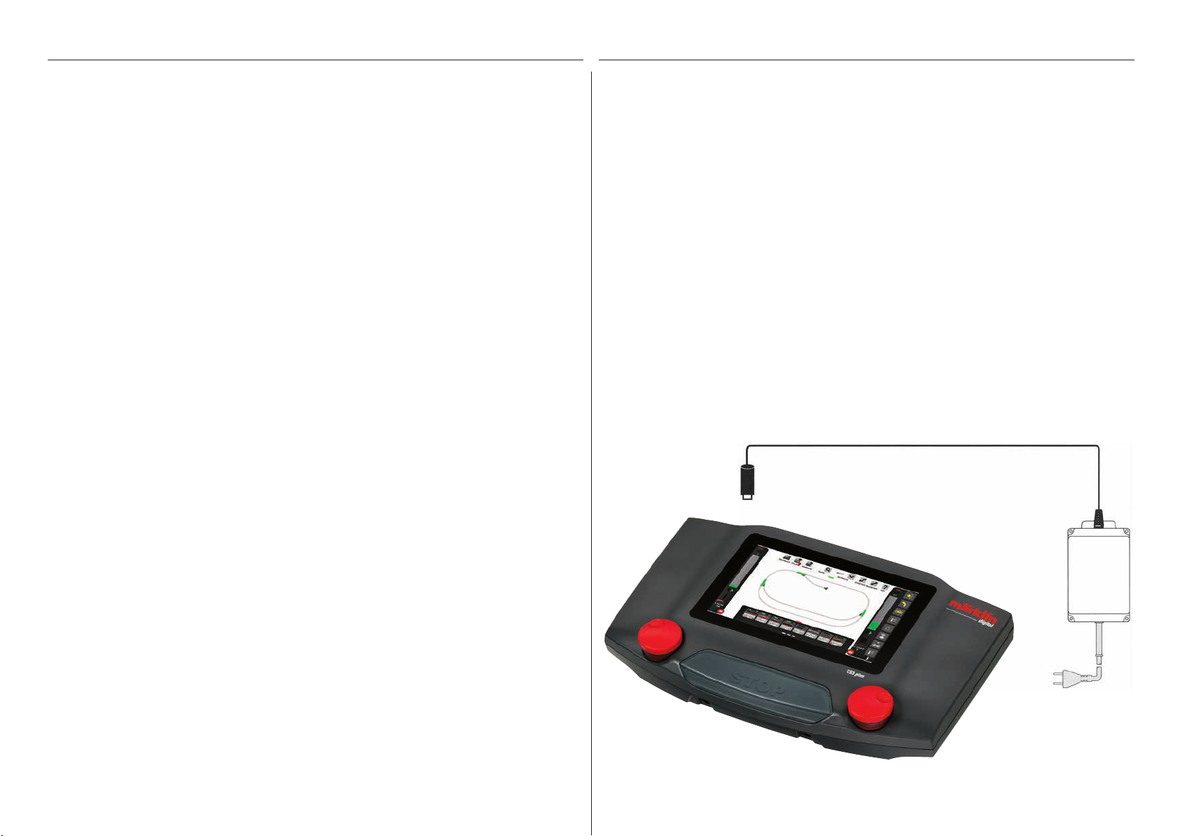
Folgende Komponenten werden zum Start benötigt
Schaltnetzteil 60061 (60 VA; für Märklin H0, Trix H0 und Minitrix) oder Schaltnetzteile 60101 bzw. 51095 (100
VA; für Märklin Spur 1 bzw. LGB), Central Station 3, Gleisanschlusskabel, Gleisanlage, Rollmaterial und/oder
Magnetartikel.
Es können ausschließlich die aufgeführten Schaltnetzteile an der CS3 verwendet werden. Transformatoren
sind nicht mehr zulässig.
Verbinden Sie die Teile gemäß nachfolgender Illustrationen. Zuerst verbinden Sie die Central Station mit der
Modelleisenbahn-Anlage, dann schließen Sie das Schaltnetzteil an und verbinden es schließlich mit einer
Haushaltssteckdose.
Anschluss Stromversorgung
Central Station
power
60061 (Märklin)
60101 (Märklin)
51095 (LGB)
Anhang
Verfügbare Funktions-Piktogramme 37
Systemarchitektur: CS3 und CS3 plus 38
2
3
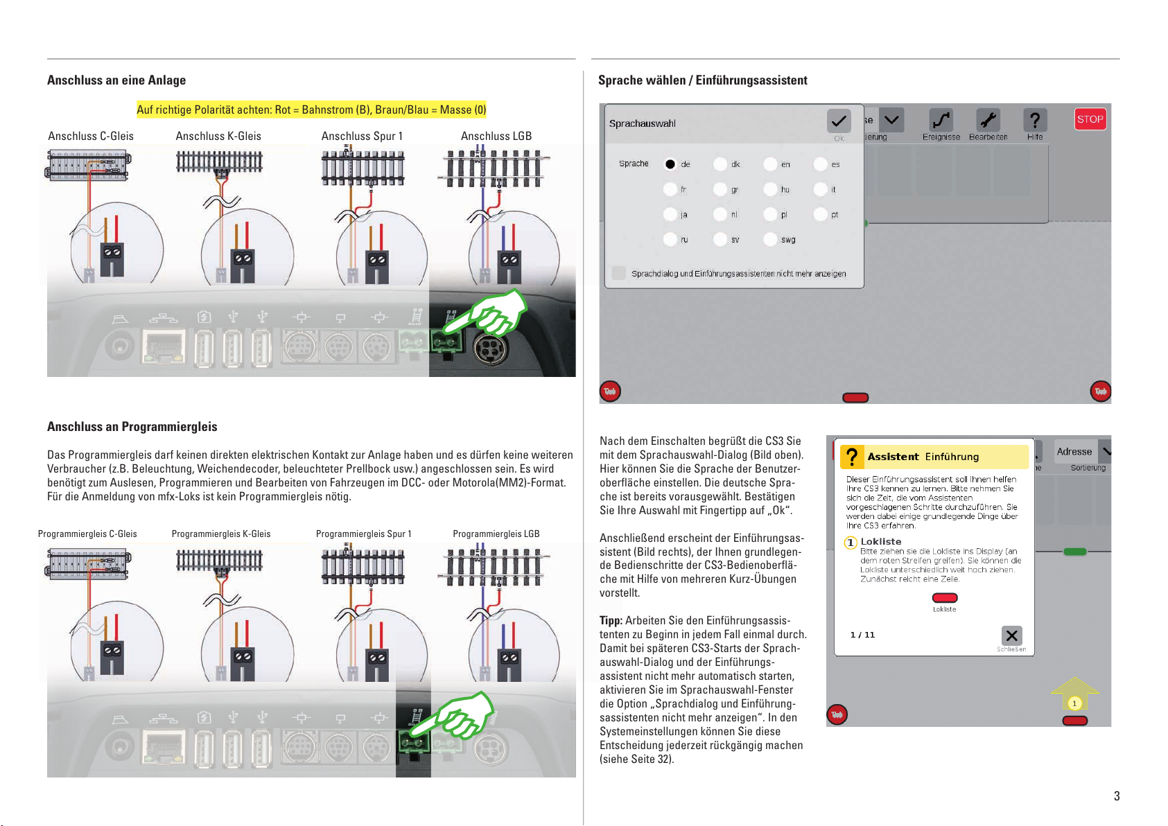
Anschluss an Programmiergleis
Das Programmiergleis darf keinen direkten elektrischen Kontakt zur Anlage haben und es dürfen keine weiteren
Verbraucher (z.B. Beleuchtung, Weichendecoder, beleuchteter Prellbock usw.) angeschlossen sein. Es wird
benötigt zum Auslesen, Programmieren und Bearbeiten von Fahrzeugen im DCC- oder Motorola(MM2)-Format.
Für die Anmeldung von mfx-Loks ist kein Programmiergleis nötig.
Anschluss an eine Anlage
Anschluss C-Gleis Anschluss K-Gleis Anschluss Spur 1 Anschluss LGB
Auf richtige Polarität achten: Rot = Bahnstrom (B), Braun/Blau = Masse (0)
Programmiergleis C-Gleis Programmiergleis K-Gleis Programmiergleis Spur 1 Programmiergleis LGB
Sprache wählen / Einführungsassistent
Nach dem Einschalten begrüßt die CS3 Sie
mit dem Sprachauswahl-Dialog (Bild oben).
Hier können Sie die Sprache der Benutzer-
oberfläche einstellen. Die deutsche Spra-
che ist bereits vorausgewählt. Bestätigen
Sie Ihre Auswahl mit Fingertipp auf „Ok“.
Anschließend erscheint der Einführungsas-
sistent (Bild rechts), der Ihnen grundlegen-
de Bedienschritte der CS3-Bedienoberflä-
che mit Hilfe von mehreren Kurz-Übungen
vorstellt.
Tipp: Arbeiten Sie den Einführungs assis-
tenten zu Beginn in jedem Fall einmal durch.
Damit bei späteren CS3-Starts der Sprach-
auswahl-Dialog und der Einführungs-
assis tent nicht mehr automatisch starten,
aktivieren Sie im Sprachauswahl-Fenster
die Option „Sprachdialog und Einführung-
sassistenten nicht mehr anzeigen“. In den
Systemeinstellungen können Sie diese
Entscheidung jederzeit rückgängig machen
(siehe Seite 32).
6
135
7
8
2
4
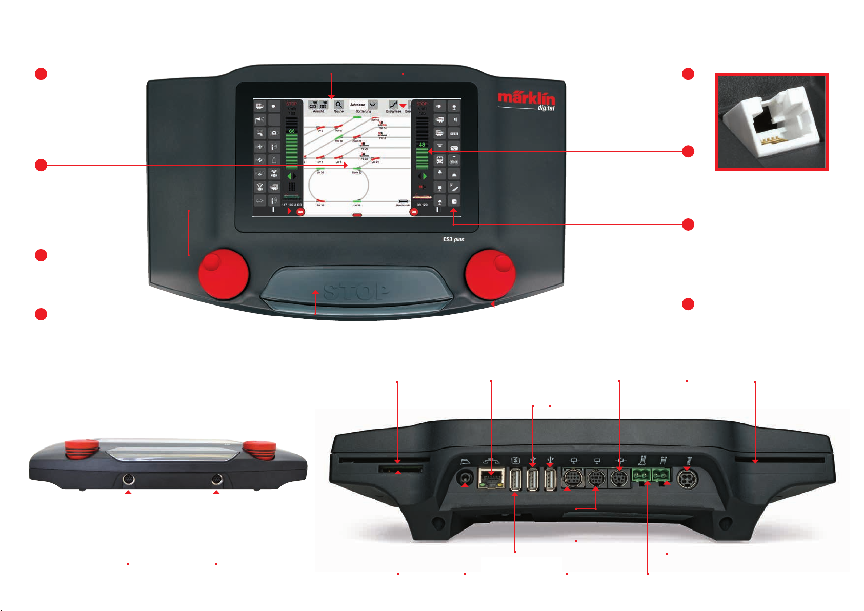
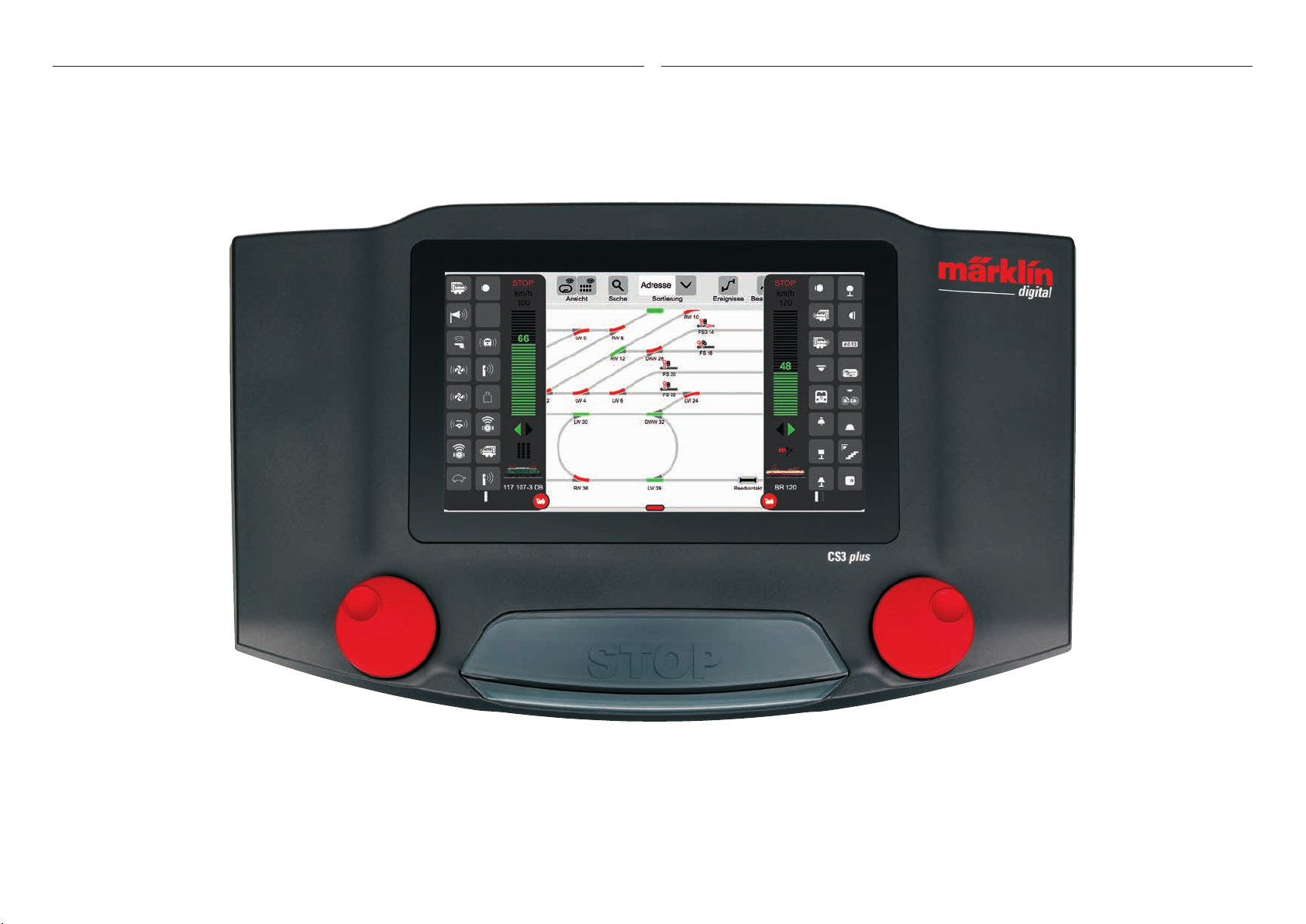
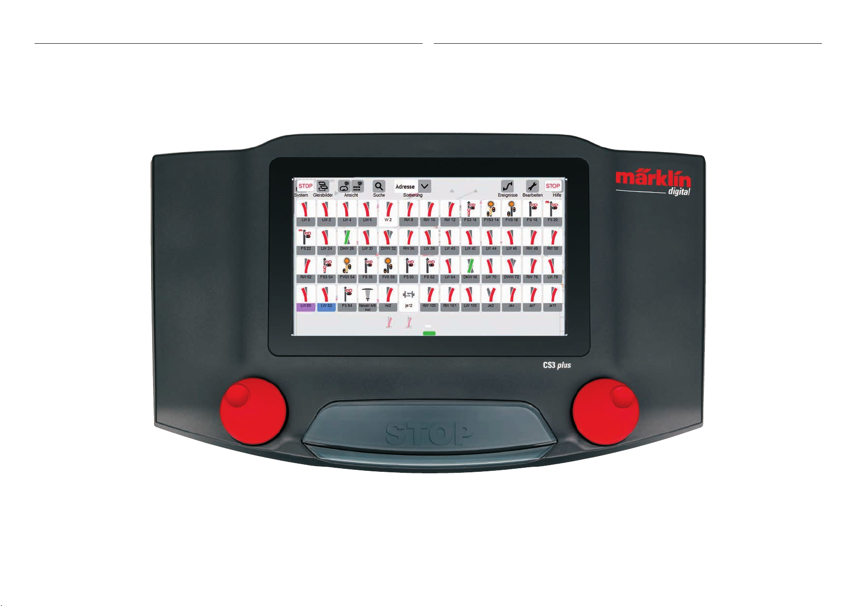
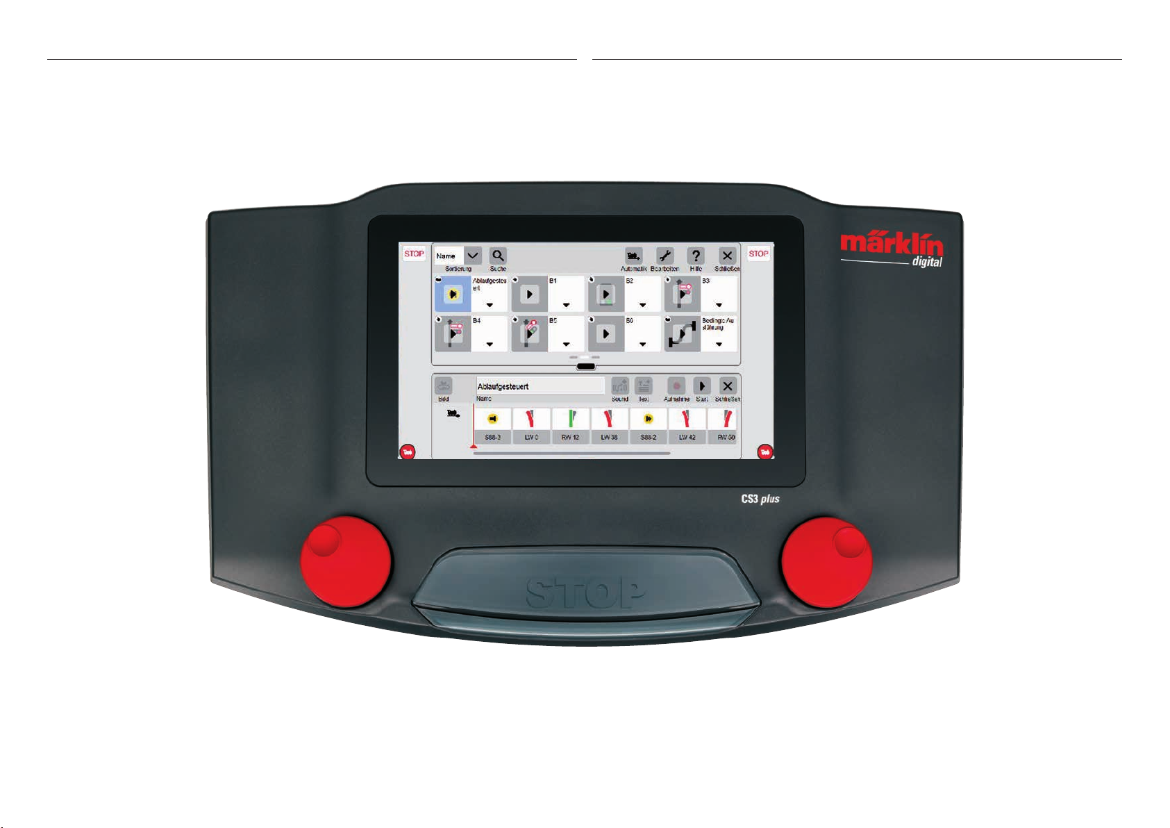
Grundfunktionen und Anschlüsse
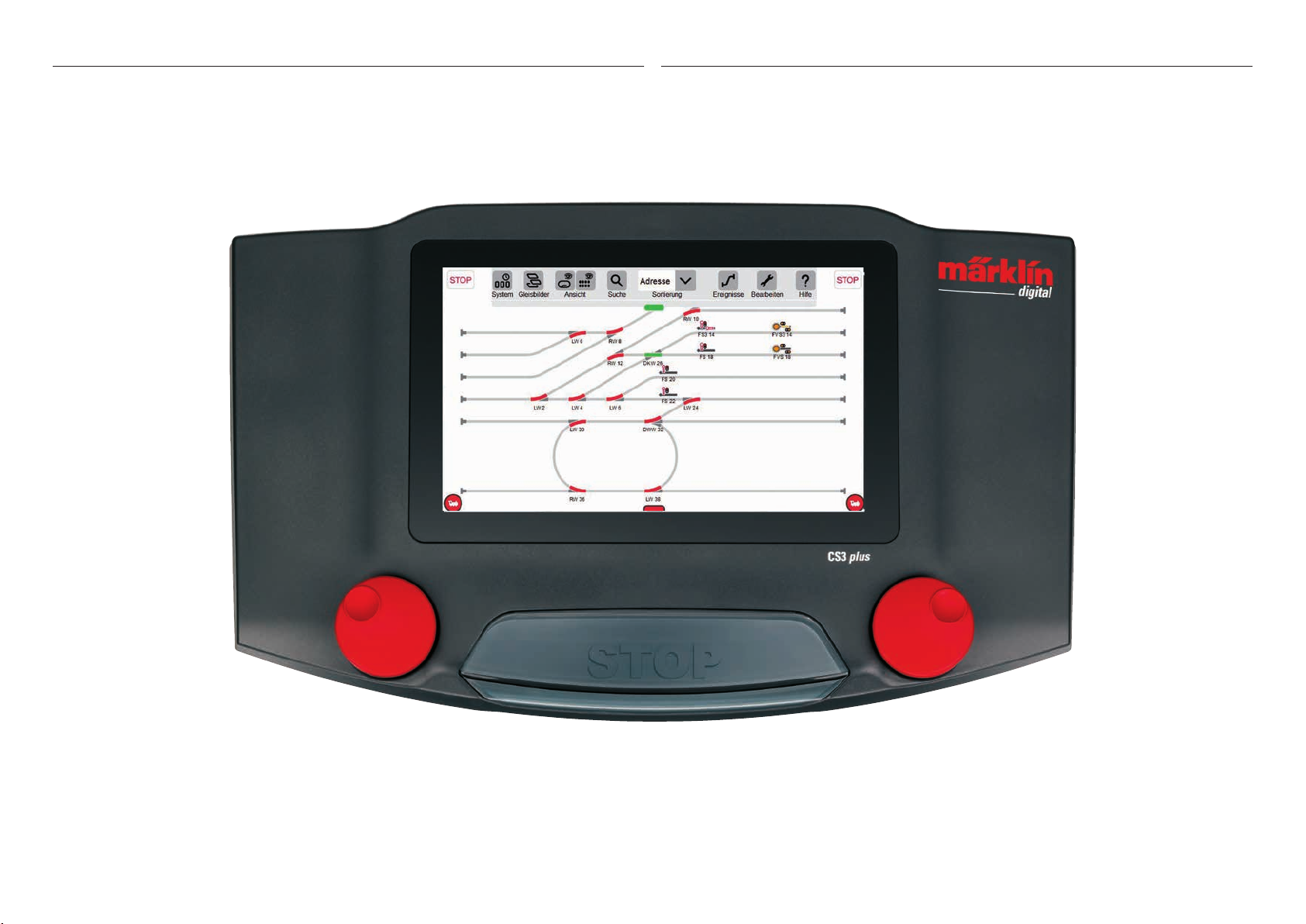
Großes Display mit
hochauflösendem Farbbildschirm inklusive
Touchscreen – alle
Funktionen sind per
Fingertipp schaltbar.
Das Gleisbild steht im
Mittelpunkt der CS3 und
liefert die wichtigsten
Infos über den aktuellen
Zustand der eigenen
Anlage.
Zwei Fahrpulte (links und
rechts) sind in der Grundeinstellung sichtbar.
Die zentrale Stop-Taste dient gleichzeitig als
„Not-Aus“ – in kritischen Fahrsituationen wohl
die wichtigste Funktion der Central Station 3.
Der Umschaltbereich: Von
hier aus gelangt man in die
verschiedenen Grundmenüs.
Einen Punkt antippen und
das neue Menü erscheint.
Praktisch: Die Geschwindigkeit
lässt sich nun per Fingerwisch
über ein vertikales Balkendiagramm regeln.
In Reihen zu je acht Positionen
werden die Funktionen der
einzelnen Loks angezeigt.
Sie lassen sich durch einen
Fingertipp aktivieren.
Über den Drehregler lässt sich die Geschwindigkeit
ebenfalls steuern. Optisch wird die Änderung im
Balkendiagramm (grün) angezeigt.
Die CS3 plus verfügt zudem
an der Unterseite über einen
direkten S88-Anschluss
Märklin CANBus Eingang
(6-polig)
Programmiergleis
Anschluss
Netzteil
Hauptgleis
Steckplatz für Chipkarte mit Lokdaten
Ausgang
Mobile Station
Ausgang
Mobile Station
Steckplatz für Chip-
karte mit Lokdaten
Slot für
SD-Speicherkarte
(max. 32 GB)
Anschluss
Netzwerk/PC
Anschluss
Lautsprecher/
Kopfhörer
USB-Anschlüsse
zum Datenaustausch
USB-Anschluss zum
Laden von Geräten
Märklin Geräteanschluss (7-polig)
Märklin CAN-Bus
Ausgang (9-polig)
4
Bedienung | Schnelleinstieg
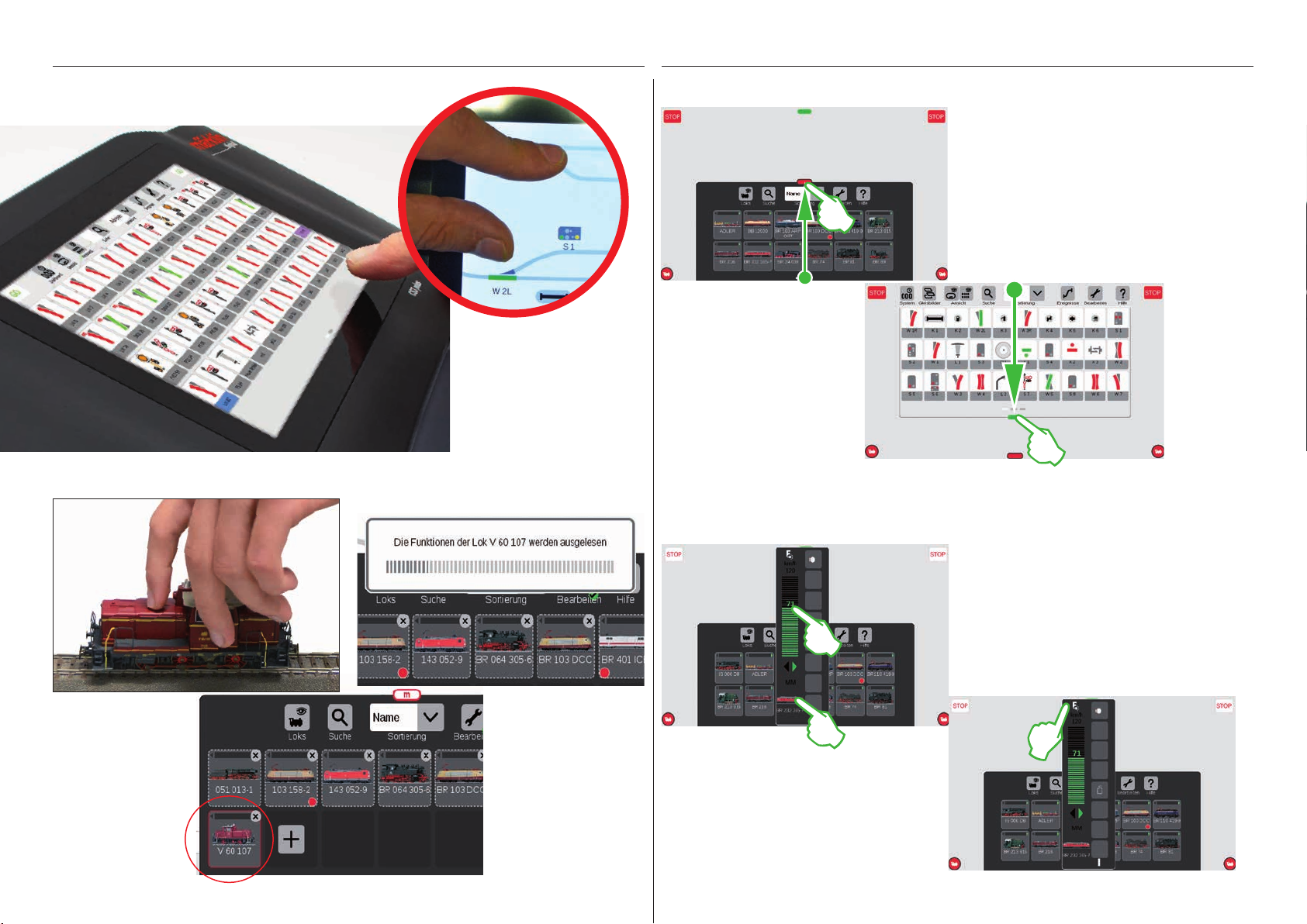
Antippen und Wischen: Arbeiten mit dem Touchscreen
Anmelden von mfx-Loks
Ziehen und zoomen: Dank des
hochauflösenden Touchscreens
genügen einfache Berührungen,
um das Gerät zu bedienen – wie
bei Smartphone oder Tablet. Um
z. B. das Gleisbild zu vergrößern,
zieht man es mit Daumen und
Zeigefinger „auseinander“.
Einfacher Zugriff auf Lok- und Artikelliste
Lokliste aufziehen: Die Lokliste lässt sich mit-
hilfe des roten Querbalkens an ihrem oberen
Rand nach Bedarf vergrößern. Einfach den
Querbalken berühren und nach oben ziehen.
Ziehen in die Gegenrichtung verkleinert die
Lokliste oder blendet sie sogar ganz aus.
Artikelliste aufziehen: Den grünen
Querbalken berühren und nach
unten ziehen: Die Artikelliste öffnet
sich soweit wie benötigt. Das Zie-
hen des Querbalkens nach oben
verkleinert die Artikelliste bzw.
blendet sie vollständig aus.
Schnellzugriff auf das Fahrpult
(Zuvor muss die Option „Popup Fahrpult“ in den Systemeinstellungen aktiviert werden, siehe Seite 32)
Lok fahren: Auf das Loksymbol tippen und die Spontansteuerung öffnet sich (Bild links). Mit Fingertipp
auf den Fahrregler stellt man die Geschwindigkeit
ein. Alternativ können Sie auch den grünen Balken
„nach oben schieben“. Schließen Sie die Spontansteuerung, indem Sie links oder rechts daneben auf
den Bildschirm tippen.
Aufstellen: Die mfx-Lok
vollständig auf das Gleis
stellen. Die Anmeldung
von mfx-Loks ist sowohl
auf dem Haupt- als auch
auf dem Programmiergleis
möglich.
Einlesen: Nach wenigen
Sekunden beginnt die
CS3 automatisch mit dem
Auslesen der Daten.
Fertig: Die neu angelegte
Lok erscheint rot umrandet in der Lokliste. Ein
rotes „m“ am Rand der
Lokliste weist ebenso auf
die Neuanmeldung der
mfx-Lok hin.
Funktionen aufrufen: Blenden Sie die
Funktionen der Lok ein, indem Sie auf das
„F“-Zeichen am oberen Ende des Fahrreg-
lers tippen (Bild rechts). Per Fingerdruck
schalten Sie die Funktionen.
5
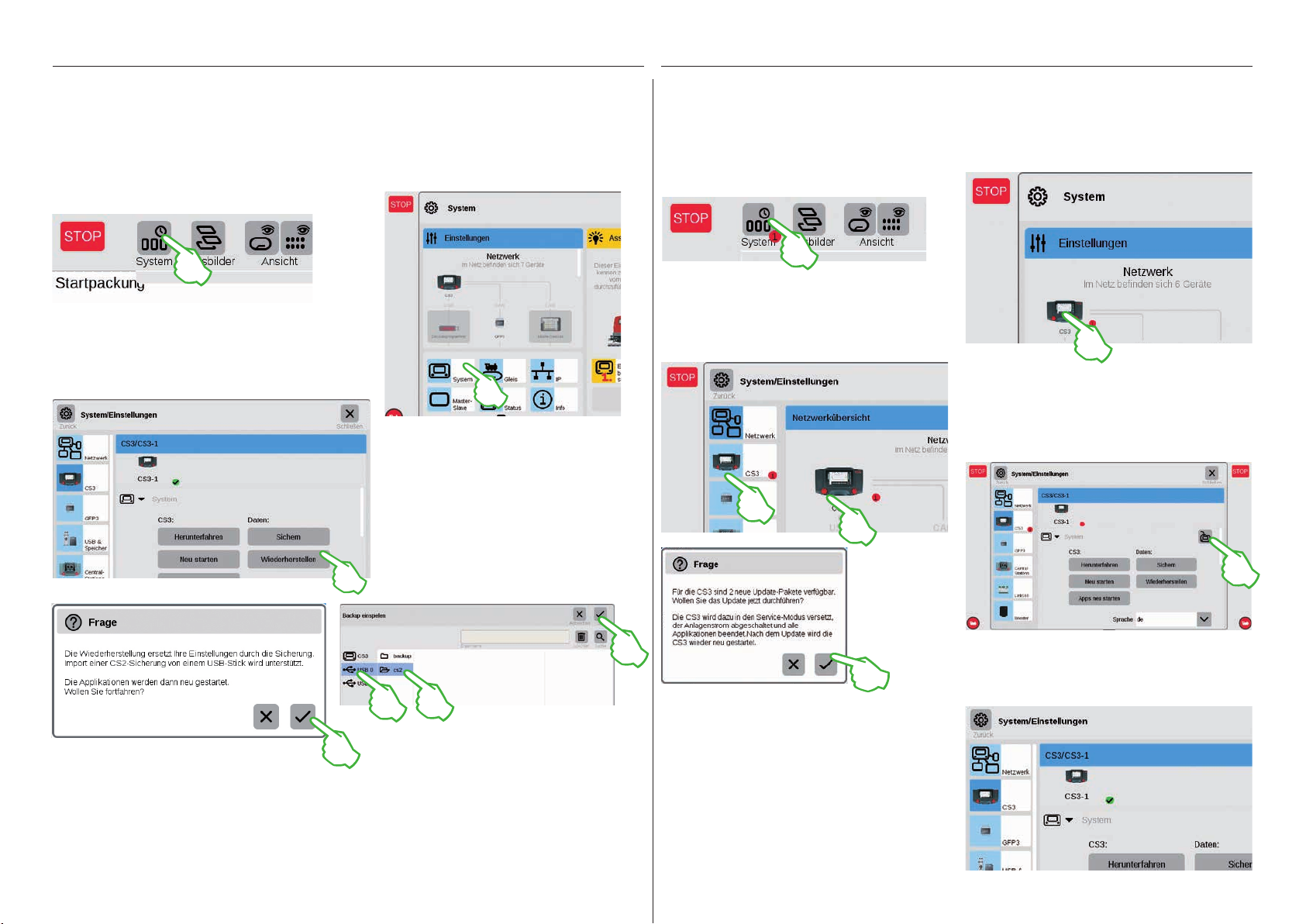
Import von CS2-Daten Aktualisierung der CS3
Import von vorhandenen Daten aus der Central Station 2
Haben Sie bisher bereits mit der Central Station 2 Ihre Anlage gesteuert? Dann können Sie Ihre wertvollen
Lok-, Magnetartikel- und Gleisdaten von dort in wenigen Schritten in die Central Station 3 übernehmen.
Alles, was Sie dafür benötigen, ist ein USB-Stick mit dem Backup Ihrer CS2-Daten. Wichtig: Stecken Sie
als ersten Schritt den USB-Stick in eine der beiden USB-Datenbuchsen auf der Rückseite der CS3.
Auf dem Startbildschirm der CS3 tippen Sie in der
linken oberen Ecke auf die „System“-Schaltfläche
(Bild oben). In der Systemübersicht tippen Sie links
unten auf „System“ (Bild rechts).
So gelangen Sie direkt in die
Systemeinstellungen der CS3. Dort
tippen Sie auf die Schaltfläche
„Wiederherstellen“.
So sind Sie immer up-to-date: Aktualisierung der CS3-Software
Märklin entwickelt die Betriebssoftware der CS3 kontinuierlich weiter. Sobald eine neuere Version verfügbar
ist, signalisiert dies ein kleiner roten Punkt am Fuß des „System“-Symbols auf dem CS3-Startbildschirm.
Tipp: Falls ein Anschluss Ihrer CS3 an das Internet nicht möglich ist, können Sie Updates auch mittels USBStick durchführen (siehe Seite 35).
Um die Firmware zu aktualisieren, tippen Sie auf
das „System“-Symbol. Der rote Punkt leitet Sie
durch die Systemeinstellungen. Tippen Sie jeweils
auf die Symbole neben dem roten Punkt.
Zunächst in der Systemübersicht (Bild oben),
dann in den Systemeinstellungen (Bild links).
Dort führen beide Möglichkeiten zum Ziel:
Zur Update-Schaltfläche (Bild unten), die Sie
mittels Fingertipp aktivieren.
Nun fragt die CS3 nach, ob Sie das Update wirklich
durchführen wollen. Bestätigen Sie, indem Sie auf
Im Dateiauswahl-Dialog tippen Sie auf „USB“ und
Nun fragt die CS3 nach, ob Sie wirklich sicher sind.
Bestätigen Sie mit Fingertipp auf den Haken.
Hinweis: Ausführliche Informationen zur Erstellung eines Backups Ihrer CS2-Daten finden Sie in der
Bedienungsanleitung Ihrer CS2.
auf das Verzeichnis, das das CS2-Backup enthält.
Wählen Sie das Backup aus und bestätigen Sie mit
„Ok“. Nach wenigen Momenten empfängt Sie der
Startbildschirm der CS3.
den Haken tippen. Es erscheinen Detail-Informationen
zum Update – bestätigen Sie rechts oben mit Fingertipp auf „Start“. Die CS3 führt daraufhin das Update
durch. Zum Schluss bestätigen Sie rechts oben mit
„Ok“.
In den System einstellungen signalisiert nun der
grüne Haken, dass die CS3 die neueste Version der
Betriebssoftware verwendet (Bild rechts).
6
Übersicht über die technischen Daten der Central Station 3 plus und Central Station 3
Einleitung
Schneller, komfortabler und noch anwenderfreundlicher: die neue Central Station 3 bietet Modellbahnern
nicht nur die aktuellste Technik einer Mehrzugsteuerung, sondern eine Bedienoberfläche, die Dank eines
modernen Touchscreens eine intuitive Steuerung ermöglicht. So wie bei modernen Smartphones und Tablets
muss der Bildschirm nur mehr berührt werden und über die Zoomfunktion können Ausschnitte vergrößert
werden. Per Fingerwisch (Drag & Drop) lassen sich zum Beispiel auch Lokomotiven schnell und einfach ins
Fahrpult übernehmen oder Magnetartikel auf das Gleisstellbild (Layout).
Erstmals bietet Märklin mit der Central Station 3 zwei Versionen der Steuereinheit an: die Central Station 3
plus (Art. 60216) und die Central Station 3 (Art. 60226). Wichtig: Die Bedienung beider Geräte ist identisch. Die
vorliegende Bedienungsanleitung gilt daher auch für beide Versionen. Die beiden Versionen der CS3
unterscheiden sich im Wesentlichen durch ihre Hardwareausstattung:
Central Station 3 plus (60216): Die Version ermöglicht den Einsatz von mehreren Central Stations parallel.
Zudem verfügt sie über einen eigenen S88-Anschluss und damit über eine direkte Anschlussmöglichkeit für
die Rückmeldemodule 60881 und 60882.
Central Station 3 (60226): Die Version ist für Anlagen ideal, die ausschließlich über eine Zentrale zu steuern
sind. S88-Rückmeldemodule sind bei ihr über den Link S88 (60883) anzuschließen.
Eine Übersicht über die Anschlussmöglichkeiten der Steuereinheiten finden Sie auf den Seiten 37 und 38.
Einen einwandfreien Betrieb stellen Sie in diesem komplexen System sicher, wenn Sie ausschließlich auf die
geprüften und getesteten Märklin-Systemkomponenten zurückgreifen. Bei der Verwendung von Fremdprodukten entfällt daher jede Herstellergarantie von Märklin. Für Schäden, die bei der Verwendung von Fremdprodukten auftreten, ist somit der Betreiber verantwortlich.
Halten Sie sich beim Anschluss der Anlage an die vorgestellten Techniken und Prinzipien aus dieser
Anleitung. Der Einsatz von anderen Schaltungen kann leicht zu Beschädigungen an den elektronischen
Komponenten führen. Verzichten Sie daher lieber auf „teuere“ Experimente.
Die Central Station ist kein Spielzeug. Stellen Sie sicher, dass dieses Gerät auch von Kindern nur als
Steuerungsgerät für die Modelleisenbahn genutzt wird. Wir wünschen Ihnen viel Freude beim Einsatz
der Central Station an Ihrer Modelleisenbahnanlage. Ihr Märklin Service-Team
Sicherheitshinweise
Benutzerwartung dürfen nicht durch Kinder ohne
• Nur für den Betrieb in trockenen Räumen.
• Verbaute LEDs entsprechen der Laserklasse 1
nach Norm EN 60825-1.
• Dieses Gerät kann von Kindern ab einem Alter von
8 Jahren und von Personen mit eingeschränkten
physischen, sensorischen oder geistigen Fähig keiten oder einem Mangel an Erfahrung und/oder
Wissen verwendet werden, wenn sie beaufsichtigt
werden oder bezüglich des sicheren Gebrauchs
des Geräts unterwiesen wurden und die daraus
resultierenden Gefahren verstanden haben. Kinder
dürfen nicht mit dem Gerät spielen. Reinigung und
Beaufsichtigung durchgeführt werden.
• Spannungsversorgung: Nur zu verwenden mit
den Schaltnetzteilen Märklin 60 Watt (60061),
Märklin 100 Watt (60101) oder LGB 100 Watt
(51095).
• Beachten Sie die Hinweise in der Anleitung zum
verwendeten Schaltnetzteil.
• Für die Reinigung des Gerätes verwenden Sie
ein feuchtes Tuch. Benutzen Sie keine Lösungsoder Reinigungsmittel. Das Gerät muss zur
Reinigung spannungsfrei sein.
• Anleitung aufbewahren.
Technische Hinweise
• Das vorliegende Gerät ist ein digitales Steuer gerät
zum Betrieb herkömmlicher Modelleisenbahnen
mit Märklin Digital, Märklin Systems, Märklin MM
oder DCC.
• Zur Erweiterung des internen Speichers kann eine
SD-Speicherkarte bis 32 GB eingesetzt werden.
• An den zwei USB-Buchsen können Maus, Tastatur
oder ein Speicherstick wahlweise direkt oder über
einen USB-Hub eingesteckt werden.
• Die USB-Ladebuchse ist zur Stromversorgung zum
Beispiel eines Tablets/WLAN-Routers (Belastung
bis max. 1 A) vorgesehen.
Einschränkungen der Central Station 60226
Da die Central Station 60226 über keinen Märklin CANBus Eingang verfügt, kann sie im Master/Slave-Betrieb nicht als Slave eingesetzt werden. Anstelle des
Märklin CAN-Bus Eingangs besitzt diese einen
zweiten Märklin Geräteanschluss.
Darüber hinaus können Rückmeldemodule nur über
den Link S88 (60883) angeschlossen werden. Der
S88-Anschluss auf der Geräteunterseite entfällt.
Inbetriebnahme
Für die erste Inbetriebnahme reicht es, die Gleise und
das Schaltnetzteil an die Central Station anzuschließen.
1. Fahrgleis und ggf. Programmiergleis an die Central
Station anschließen.
2. Central Station mit dem Schaltnetzteil verbinden.
3. Schaltnetzteil mit dem örtlichen Stromnetz
verbinden.
Wir empfehlen die Verwendung einer schaltbaren
Steckdosenleiste, an der alle Netzteile der
Modellbahnanlage angeschlossen werden.
4. Die Central Station startet automatisch.
5. Beim ersten Start können Sie die Spracheinstellungen vornehmen und werden mithilfe eines
Start-Assistenten durch das Gerät geführt.
Es sind weitere Assistenten in das Gerät integriert,
die Sie in die Einzelheiten der Central Station
einführen werden.
• Betriebshöhe nicht über 2.000 Meter.
• Das Gerät ist nur mit Sicherheits-Kleinspannung
(SELV) entsprechend der Kennzeichnung auf dem
Typenschild zu versorgen.
Hinweis: Durch einen langen Druck auf die STOPTaste (bis zu 10 Sek.) können Sie das Abschalten der
Central Station erzwingen. Ein weiterer Druck auf die
STOP-Taste führt dann wieder zum Start der Central
Station.
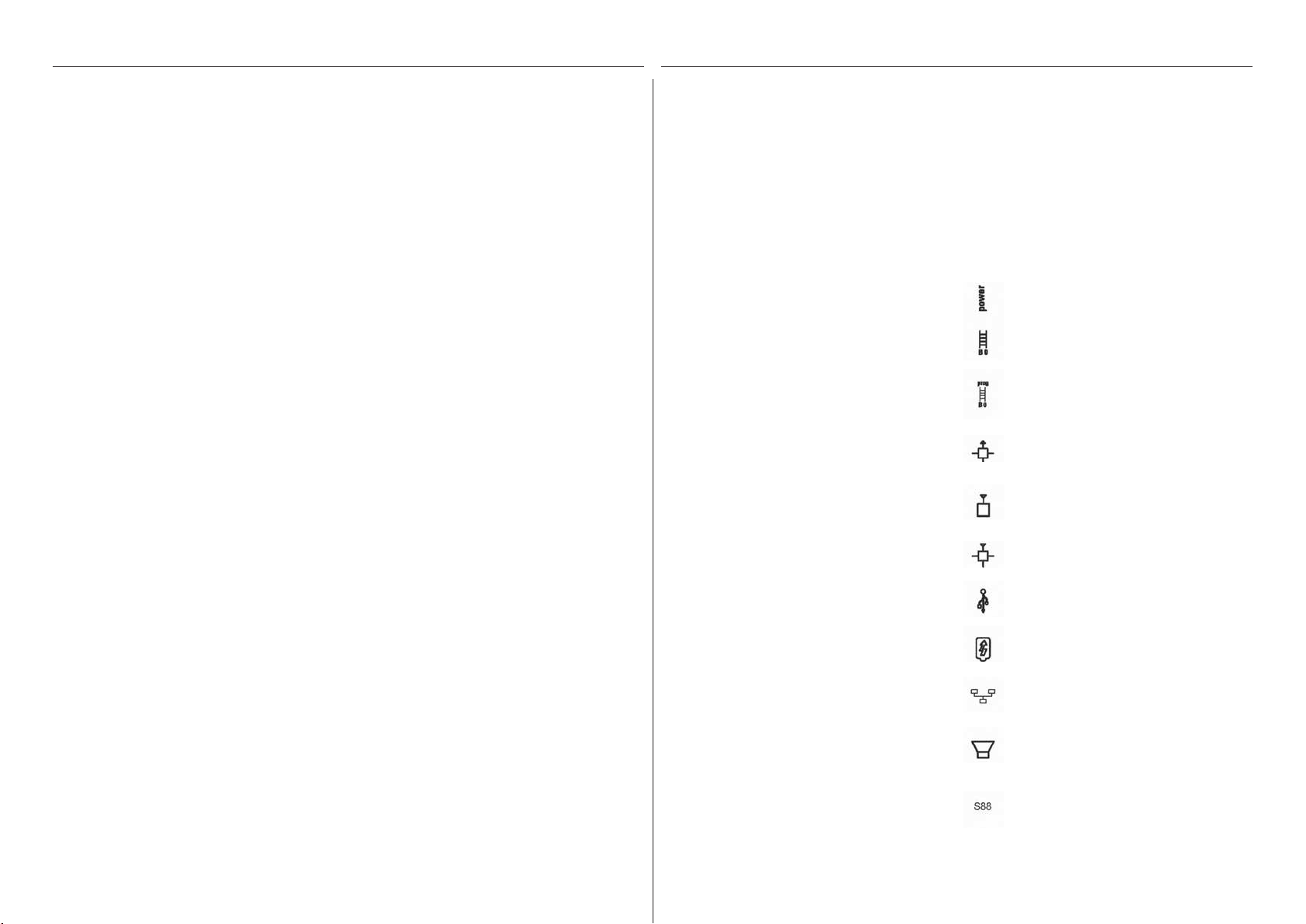
Anschlüsse
Schaltnetzteil
Gleisanschluss (max. 5 A)
Programmiergleis-Anschluss (max. 1,5 A);
Anschlussschema wie beim Fahrgleis
Märklin CAN-Bus Eingang
(6-polig; nur bei 60216)
Märklin Geräteanschluss
(7-polig) für Booster (60175/60174), Adapter
6021 (60128) und Link S88 (60833)
Märklin CAN-Bus Ausgang (9-polig)
USB: Maus, Tastatur, Speicher, Hub, ...
USB: nur zum Laden
LAN, direkte Verbindung zu einem Router
Line Out, Anschluss eines aktiven
Lautsprechers
Anschluss auf der Geräteunterseite für
Decoder S88 60881/60882, (nur bei 60216)
7
Fahren
Lokliste . Funktionen schalten . Loks bearbeiten
8
Auswählen und fahren
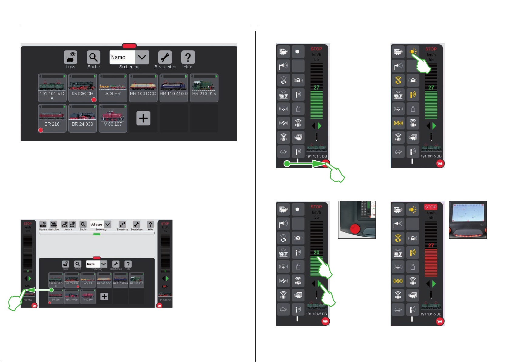
Loks in Lokliste aufnehmen: Automatische Anmeldung der mfx-Loks
Zu Beginn empfiehlt es sich, zunächst alle mit mfx-Decoder ausgerüsteten Loks anzumelden
(siehe Schnelleinstieg auf Seite 5). Das ist der einfachste Weg, die Lokliste zu füllen (Bild oben)
und gleich zu starten.
Tipp: Es können mehrere mfx-Loks zugleich angemeldet werden. Empfehlenswert ist es aber,
sie nacheinander hinzuzufügen. Dies geht erfahrungsgemäß schneller.
Tipp: Achten Sie darauf, dass die STOP-Taste nicht aktiviert ist. Im Stop-Modus sind keine
Anmeldungen möglich.
Funktionen einblenden
Fahren mit Fahrregler
Ziehen Sie den roten
Kreis mit kleiner weißer Lok in Richtung
Bildschirmmitte:
Die Lok-Funktionen
werden sichtbar,
acht Funktionen pro
Spalte. Je nachdem,
wie weit Sie die Liste
aufziehen, können
bis zu 32 Funktionen
auf einmal dargestellt werden.
Funktionen schalten
Durch Antippen der
Funktionssymbole
werden die Funktionen geschaltet.
Im Bild links sind
beispielsweise
das Licht, das An-/
Abkuppeln, die
Pfeife und der Lüfter
aktiviert.
Tipp: Das Antippen
des roten Kreises
blendet das Fahrpult
aus – und blendet es
auch wieder ein.
Nothalt / Stop
Loks ins Fahrpult ziehen
Um eine Lok auszuwählen,
ziehen Sie sie aus der Lokliste
zum linken (wie hier im Bild)
In der Lokliste hebt jeweils ein kleiner
roter Punkt die beiden in den Fahrpulten
aktiven Loks hervor.
oder zum rechten Bildschirmrand. Über dem automatisch
eingeblendeten Fahrpult lösen
Sie den Finger vom Display.
Im Fahrpult werden nun die
ausgewählte Lok, das mfx-Protokoll, der grüne Fahrtrichtungspfeil, der Geschwindigkeitsregler und ganz oben das
STOP-Bedien element angezeigt. Fährt eine Lok, wird dies
auch in der Lokliste mit einem
grünen Balken am oberen Rand
des Lok-Symbols angezeigt.
Tippen Sie auf den
Fahrregler, der grüne
Balken wird sichtbar: die Lok fährt.
Alternativ wischen Sie
über den Balken oder
steuern mit dem roten
Drehknopf – auch
wenn das Fahrpult
ausgeblendet ist. Mit
dem grünen Pfeil –
oder mit Druck auf den
Drehregler – wechseln
Sie die Fahrtrichtung.
Wenn der
Geschwindigkeitsbalken in rot
dargestellt wird, ist
der Stop-Modus
aktiviert. Um ihn
zu lösen, drücken
Sie die STOP-Taste
oder tippen auf das
STOP-Symbol am
oberen Ende des
Fahrpults.
9
Lokliste: Loks sortieren und suchen
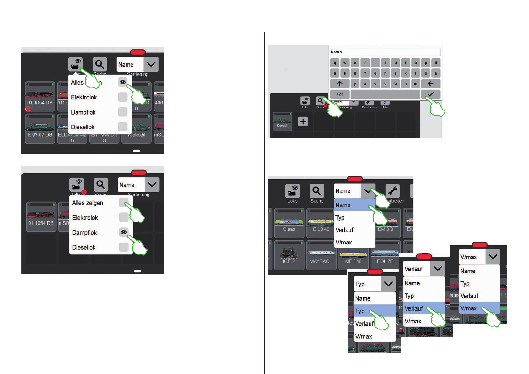
Anzeige der angemeldeten Loks abhängig von der Antriebsart Bestimmte Loks suchen / Live-Suche
Um Ihnen größere Übersicht zu geben, lässt sich
die Lokliste anhand der
Antriebsart filtern.
Mit Fingertipp auf das
Lok-Symbol am oberen
Rand der Lokliste öffnet
sich ein kleines Menü.
Tippen auf das Lok-Symbol
blendet das Auswahlmenü
wieder aus.
Wichtig: Um einzelne Traktionen
anzuzeigen, muss „Alles anzeigen“
deaktiviert sein.
Ein Fingertipp z. B. auf „Dampflok“ zeigt
alle Lokomotiven mit Dampftraktion an.
Die übrigen sind ausgeblendet. Der
kleine rote Punkt zeigt an, dass der
Filter aktiviert ist.
Der kleine rote Punkt am Fuß des Lupen-Symbols
signalisiert, dass die Suchfunktion aktiviert ist.
Die verschiedenen Sortiermöglichkeiten
Sie wollen eine
bestimmte Lok finden?
Tippen Sie auf die mit
„Suche“ beschriftete
Lupe am oberen Rand
der Lokliste und geben
Sie den Namen bzw.
einen Teil des Namens
ein. Die CS3 führt direkt
nach der Eingabe jedes
Zeichens eine Live-Suche durch. Wichtig: Um
die Suche zu beenden, ist der komplette
Suchbegriff wieder zu
löschen.
Noch mehr Übersicht verschaffen
Sie sich mithilfe des Aufklapp-Menüs
am oberen Rand der Lokliste. Einfach
drauftippen und das Menü öffnet
sich. Sie können nach Loknamen sortieren, indem Sie auf „Name“ tippen.
Die Züge werden dann alphabetisch
sortiert (siehe links).
Tipp: Nach einer Traktionswahl (z. B.
Dampflok/Diesellok) blenden Sie mit
„Alles anzeigen“ die gesamte Lokliste
schnell wieder ein.
Ein Tippen auf „Typ“ sortiert
die Lokliste nach dem Loktyp in
der Reihenfolge Dampf, Diesel,
Elektro, Sonstige. Wählen
Sie „Verlauf“, so werden die
zuletzt genutzten Loks zuerst
angezeigt. „V/max“ sortiert
die Lokliste nach der bei den
Einstellungen unter „Tacho“
angegebenen Höchstgeschwin-
digkeit (siehe Seite 11).
10
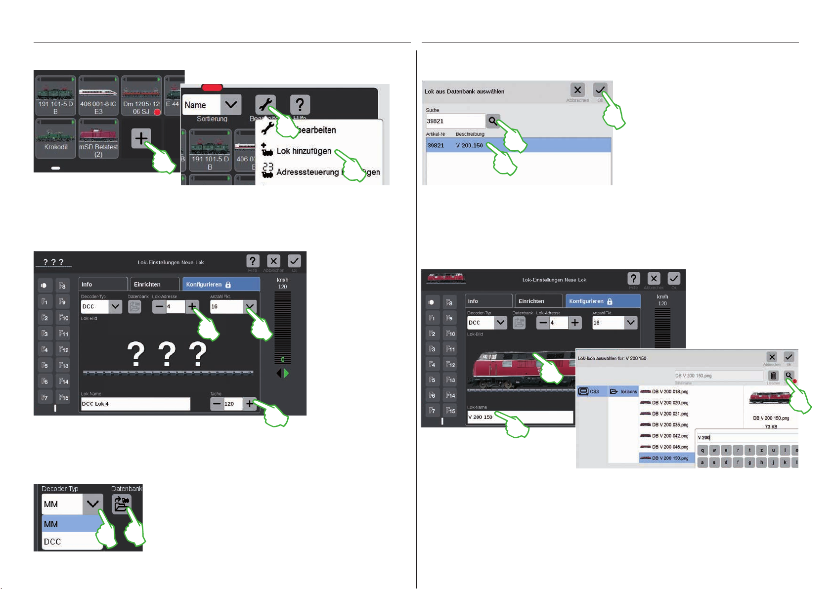
Loks manuell hinzufügen
So fügen Sie weitere Loks hinzu: Im Suchdialog tippen Sie auf das Lupensymbol und blenden damit eine Tastatur ein. Auf dieser geben Sie die
Loks ohne mfx-Decoder fügen Sie von Hand hinzu. Dazu tippen Sie einfach auf das große
Pluszeichen am Ende der Lokliste. Alternativ tippen Sie auf das Werkzeugsymbol („Bearbeiten“) in
der Lokliste und wählen im eingeblendeten Menü „Lok hinzufügen“. Die Lok-Einstellungen werden
eingeblendet, der „Info“-Reiter ist aktiv. Dort werden alle Einstellungen angepasst (Bild unten).
Im Feld „Lok-Adresse“
stellen Sie mit Tippen auf
Minus- bzw. Pluszeichen
die Lok-Adresse ein. Wichtig: Wenn die Adresse in
rot erscheint, ist sie bereits
vergeben. Dann einfach
solange weiter auf „Plus“
tippen, bis die Farbe wieder auf schwarz wechselt.
Rechts davon finden
Sie das Aufklapp-Menü
„Anzahl Fkt.“, in dem Sie
die Anzahl der belegbaren
Funktionen einstellen
können.
Artikelnummer oder den Loknamen ein: Das System beginnt sofort mit der Suche. Jedes weitere eingegebene
Loks mit DCC-Decoder hinzufügen
Bei einer Lokomotive mit DCC-Decoder geben Sie zunächst im Feld „Lok-Name“ am unteren Displayrand die Bezeichnung der Lok ein. Die CS3 sucht dann automatisch nach dem passenden Bild und fügt es ein (Bild unten).
Die CS3 verfügt bereits ab Werk über eine Vielzahl von Lokbildern.
Zeichen macht die Suchergebnisse genauer
(Live-Suche). Anschließend wählen Sie die gesuchte Lok aus und bestätigen mit „Ok“.
Tipp: Ziehen Sie die Suche mittels der Artikel nummer vor, da diese eindeutig ist.
Falls die CS3 kein passendes
Bild zuordnen kann, hilft unter
Umständen ein direkter Blick
in die Lokbilder-Datenbank:
Sie öffnen sie mit Fingertipp
auf die Bildfläche in der Mitte
des Displays.
Im Feld „Tacho“ legen Sie die Höchstgeschwindigkeit fest, die im Fahrpult angezeigt wird.
In der Suchmaske tippen Sie auf die Lupe,
geben den Loknamen ein und wählen
Loks mit MM-Decoder hinzufügen
Eine Lokomotive mit MM-Decoder lässt sich mithilfe der integrierten Lokdatenbank sehr komfortabel der Lokliste hinzufügen. Zunächst wählen Sie
am linken oberen Rand der Registerkarte „Info“ im Feld „Decoder-Typ“
die Option „MM“ (Bilder oben und links). Dann tippen Sie direkt daneben
auf das mit „Datenbank“ bezeichnete Symbol. Eine Suchmaske öffnet
sich (Bild rechts oben).
aus den angebotenen Alternativen. Zum
Eigene Lokbilder verwenden
Die Lokbilder-Datenbank der CS3 können Sie auch mit eigenen Lokbildern erweitern. Der einfachste Weg führt
über die Web-Oberfläche der CS3. Details dazu finden Sie auf Seite 35.
Schluss bestätigen mit „Ok“.
11
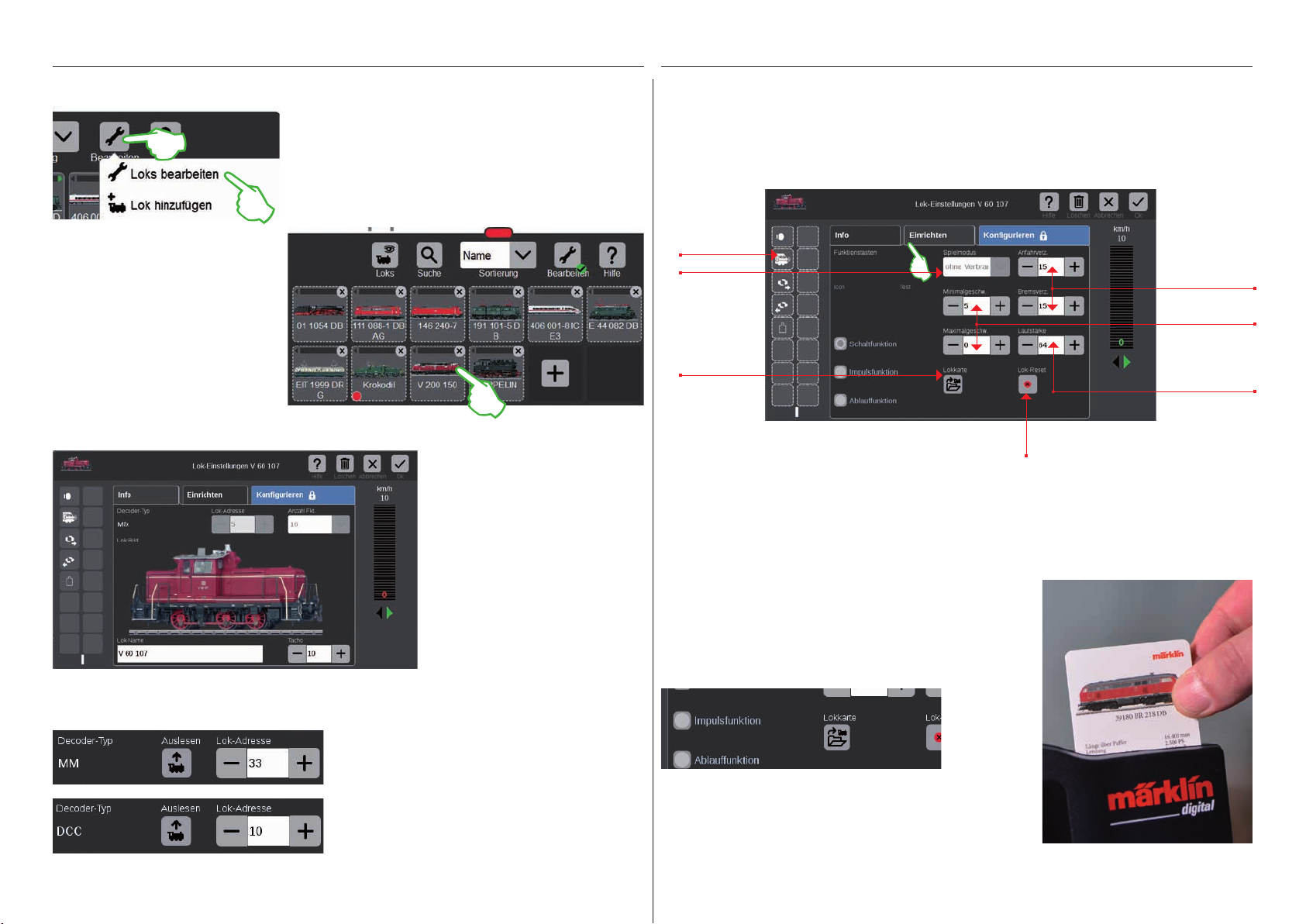
Lokeinstellungen bearbeiten | Lokkarte
In Bearbeitungsmodus wechseln
Nun können Sie die
Einstellungen der Loks
bearbeiten: Tippen Sie
dazu auf die gewünschte
Lok (Bild rechts) und
die Lok-Einstellungen
werden geöffnet
(Bild unten).
Registerkarte „Info“: Hauptdaten ändern
Den Bearbeitungsmodus aktivieren Sie zunächst mit Fingertipp auf das Werkzeugsymbol und dann auf „Loks bearbeiten“
(Bild links). Sie erkennen ihn am grün hinterlegten Haken am
Fuß des Werkzeugsymbols (Bild unten): Alle Loks erscheinen
nun mit einer gestrichelten Umrandung und können mittels
einer kurzen Berührung des „X“ gelöscht werden.
Sie befinden sich nun in der
geöffneten Registerkarte „Info“
der Lok-Einstellungen. Auch bei
mfx-Loks können Sie hier – falls
gewünscht – den Namen und
die auf dem Fahrpult angezeigte
Höchstgeschwindigkeit ändern.
Registerkarte „Einrichten“: Wichtige Einstellungen und Funktionen ändern
Zu den Lok-Einstellungen gelangen Sie, indem Sie zunächst in der Lokliste den Bearbeitungsmodus aktivieren und die zu bearbeitende Lok wählen (siehe Abschnitt „In Bearbeitungsmodus wechseln“ links auf dieser Seite). Tippen Sie anschließend auf den Reiter „Einrichten“.
Einrichten der
Funktionen
Spielmodus
einstellen (bei
mfx+-Decoder)
Lok-Daten auf
eine Lokkarte
übertragen
Lok auf Werkseinstellung
zurücksetzen
Wichtig: Geänderte Daten werden sofort im Lokdecoder gespeichert. MM- und DCC-Loks
müssen zur Bearbeitung auf dem Programmiergleis stehen
Spezialfall Lokkarte: Lok-Daten auslesen und abspeichern
Anfahr- und
Bremsverzögerung festlegen
Minimal- und
Maximalgeschwindigkeit einstellen
Lautstärke
einstellen
Sie können Loks aus vorhandenen Karten in die Lokliste übernehmen
oder eine Lokkarte neu beschreiben.
Lesen: Stecken Sie die Lokkarte wie abgebildet in den Kartenleser
ein. Die Daten werden in die Lokliste übernommen und Sie können
die Lok sofort fahren. Wichtig: Achten Sie darauf, dass der Chip der
Karte nach unten zeigt.
Adresse des Lok-Decoders auslesen
Am oberen Rand der „Info“-Registerkarte
der Lok-Einstellungen finden Sie bei MMund DCC-Loks die Option „Auslesen“: Tippen
Sie darauf und die CS3 übernimmt die im
Lok-Decoder eingestellte Adresse.
Tipp: Eine neue Lok muss zuvor hinzugefügt
werden (siehe Seite 11).
Schreiben: Stecken Sie die Lokkarte wie abgebildet in den Kartenleser ein. Tippen Sie im Reiter „Einrichten“ in den Lok-Einstellungen
auf das Symbol „Lokkarte“: Die CS3 schreibt die Lok-Daten auf die
Lokkarte.
12
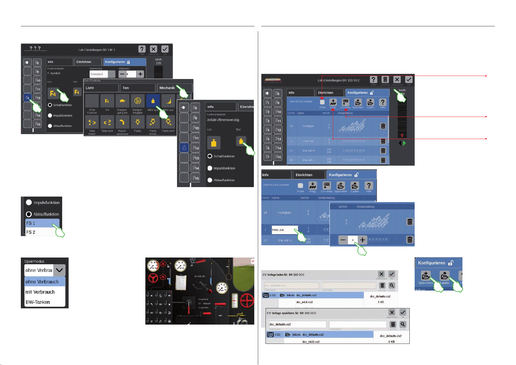
Konfigurieren | CV-Werte ändern
Funktionen einrichten
Aufgeteilt auf die drei Reiter „Licht“, „Ton“ und „Mechanik“ stehen hier
zahlreiche unterschiedliche Funktionssymbole zur Auswahl zur Verfügung. Im Beispiel tippen wir auf den Reiter „Mechanik“ und wählen das
Anfahr-/Bremsverzögerungs-Symbol. Nun ersetzt die CS3 das „F4“-Platzhaltersymbol mit dem Icon der neu gewählten Aktion (Bild rechts).
Funktionstyp auswählen und testen
Zusätzlich können Sie festlegen, auf welche Weise die ausgewählte Aktion geschaltet
werden soll: Wollen Sie die Aktion an- und abschalten können, wählen Sie „Schaltfunktion“ (Bild rechts). „Impulsfunktion“ aktiviert den Befehl für einen kurzen Moment. Mit der
Option „Ablauffunktion“ (Bild links) haben Sie Zugriff auf selbst definierte Funktionsabläufe (siehe Kapitel „Ereignisse“ ab Seite 27). Um das neu eingerichtete Funktionsfeld zu
testen, tippen Sie auf das mittig angeordnete„Test“-Element (Bild rechts oben).
Um der Lok eine Funktion zuzuweisen, tippen Sie auf ein Funktionsfeld auf der linken Seite, zum
Beispiel „F4“. Nun erscheint das
„F4“-Symbol in der Fenstermitte.
Mit Fingertipp darauf öffnet sich eine Eingabemaske (kleines Bild links).
So bearbeiten Sie einzelne CV-Werte
Nach Aktivieren des Bearbeitungsmodus und der Auswahl der zu bearbeitenden Lok (siehe Abschnitt „Einrichten“ auf Seite 12) tippen Sie auf den Reiter „Konfigurieren“. Bei einer Lok mit DCC-Decoder erscheint folgende
Oberfläche; bei einem MM-Decoder sieht die Registerkarte ähnlich aus. Tipp: Die blauen Bereiche sind nur für
Experten gedacht. Bitte ändern Sie nur etwas, wenn Sie wissen, was Sie tun.
Mit der Option POM (Programming on the Main) sind
dafür geeignete DCC-Decoder auch auf dem Hauptgleis programmierbar.
Mit „CV Hinzu“ fügen Sie
weitere CV-Reihen hinzu.
Den Inhalt einer geladenen
Vorlagendatei in den Lok-Decoder übertragen.
In den einzelnen CV-Reihen können Sie den Namen und die Werte
der CVs ändern. Zugriff auf die
Eingabefelder erhalten Sie, indem
Sie auf das jeweilige Feld tippen.
Spielewelt-Modus
Bei Lokomotiven mit mfx+Decoder können Sie auf der
Registerkarte „Einrichten“
den gewünschten Spielewelt-Modus über das
Aufklapp-Menü „Spielmodus“
einstellen. Voreingestellt ist
der Modus „ohne Verbrauch“
(Führerstand, ohne Simulation
des Betriebsmittelverbrauchs). Alternativ gibt es die
Optionen „mit Verbrauch“ (Führerstand mit Simulation
des Betriebsmittelverbrauchs) und „BW-Tanken“ (Simulation des Betriebsmittelverbrauchs plus Nachtanken im
Betriebswerk mittels Rückmeldekontakten).
Wichtig: Der Führerstand wird angezeigt, wenn Sie
das Fahrpult vollständig zum gegenüberliegenden
Displayrand aufziehen.
CV-Vorlagen laden und speichern
Um eine CV-Vorlage zu laden oder
eine erstellte Vorlage abzuspeichern,
tippen Sie in der Registerkarte „Konfigurieren“ auf die Symbole „Laden“
bzw. „Speichern“. Daraufhin wird ein
Dateiauswahl-Dialog eingeblendet
bzw. zur Speicherung ein Datei name
vorgeschlagen (Bilder links).
13
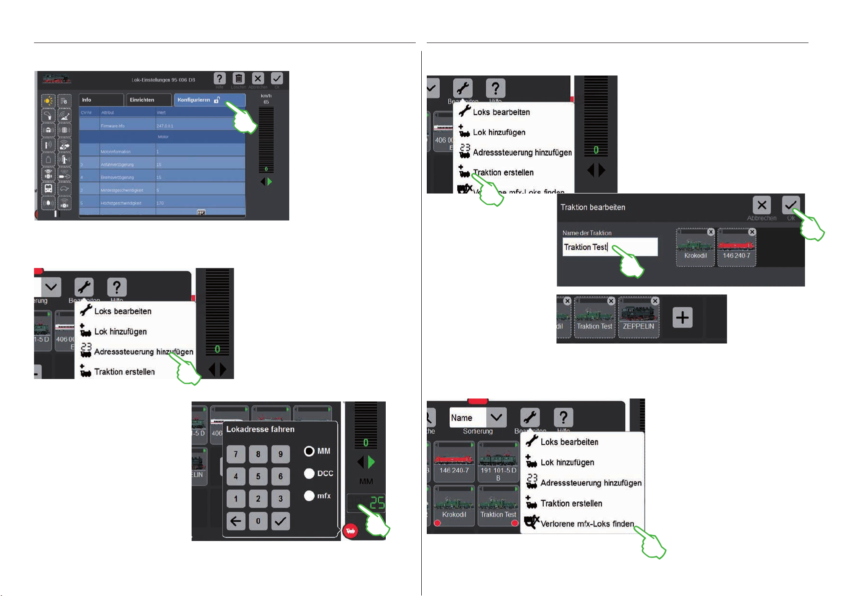
mfx-Loks konfigurieren
Loks zu einer Traktion zusammenfügen
Lok mit Adresssteuerung fahren
Sobald Sie in den Lok-Einstellungen einer mfx-Lok die
Registerkarte „Konfigurieren“
öffnen, werden alle Detail-Einstellungen des Lokdecoders
geladen.
Wichtig: Die blauen Bereiche
sind nur für Experten gedacht.
Bitte ändern Sie nur etwas,
wenn Sie wissen, was Sie tun.
Im Normalbetrieb müssen
Sie an dieser Stelle keinerlei
Anpassungen vornehmen.
Um eine Lok über ihre Adresse direkt
anzusteuern und zu fahren, tippen Sie
in der Lokliste auf das Werkzeugsymbol
(„Bearbeiten“) und im sich öffnenden
Aufklappmenü wählen Sie „Adresssteuerung hinzufügen“ (Bild links).
Eine Doppel- oder Mehrfachtraktion legen
Sie mit dem Menüpunkt „Traktion erstellen“ an
(Bild links). Das Aufklappmenü öffnen Sie mit
Fingertipp auf das Werkzeugsymbol in der
Lokliste („Bearbeiten“). In der daraufhin
eingeblendeten Eingabemaske können Sie
der neuen Traktion einen Namen geben.
Um die Traktion zu erstellen,
ziehen Sie die gewünschten
Loks mit einem Fingerwisch aus
der Lokliste in die Eingabe-
maske herüber (mittleres Bild
rechts). Bestätigen Sie, indem
Sie auf „Ok“ tippen – und die
neue Traktion erscheint in der
Lokliste (Bild rechts).
Verlorene mfx-Loks finden
Auf der eingeblendeten numerischen
Tastatur geben Sie die Adresse der Lok ein
und wählen das Protokoll des genutzten
Decoders. Im Fahrpult wird automatisch
die eingegebene Adresse übernommen
(im Beispiel rechts die Adresse 25) – nun
können Sie die Lok direkt fahren.
Adresse und Protokoll einer solchen
Adress steuerungs-Lok können Sie jeder-
zeit ändern: Tippen Sie einfach auf die
Adressdarstellung, die Tastatur erscheint
dann erneut (Bild rechts).
In seltenen Fällen kann es vorkommen, dass
eine mfx-Lok in der Lokliste nicht mehr angezeigt wird. Dann ist diese Option hilfreich.
Alle vorhandenen Daten werden überprüft
und das System auf fehlende mfx-Loks hin
untersucht.
Die Funktion starten Sie in der Lokliste über
die Schaltfläche „Bearbeiten“ und anschließendem Fingertipp auf „Verlorene mfx-Loks
finden“.
14
Artikelliste bearbeiten
Magnetartikel anlegen . sortieren . schalten
15
Magnetartikel hinzufügen
Vorbereitung
Im Auslieferungszustand ist in der Central Station 3 die Märklin Startpackung abgebildet – mit einer wenige
Magnetartikel umfassenden Artikelliste und einem einfachen Gleisbild. Sollten Sie das Gleisbild und die Artikel
nicht benötigen, sollten Sie in jedem Fall die Artikel löschen. Zudem können Sie auch gleich eine neue Platte mit
selbstgewähltem Namen anlegen.
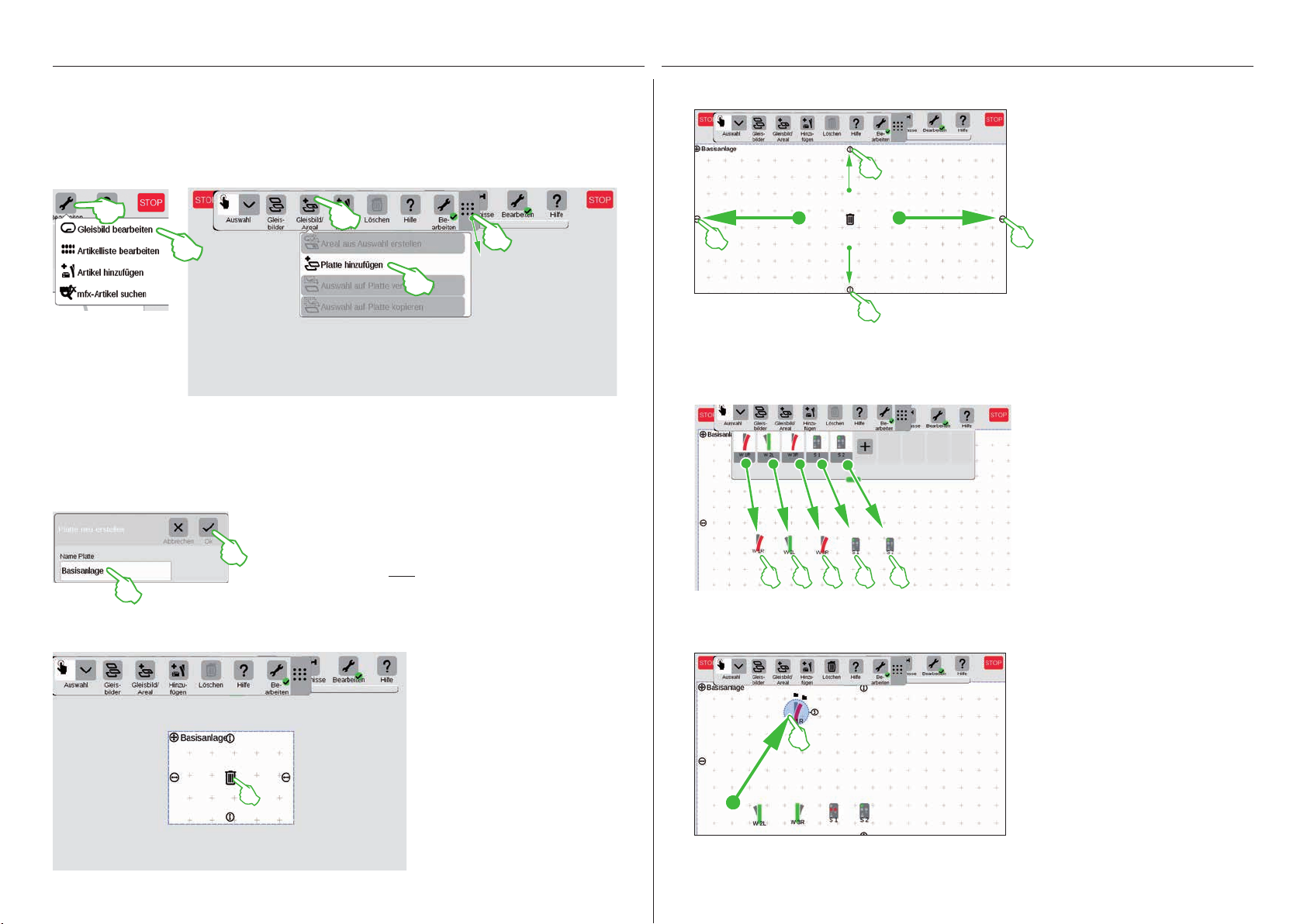
Vorhandene Magnetartikel löschen
Um einen Artikel aus der CS3 zu entfernen,
tippen Sie zunächst in der Symbolleiste
der Artikelliste auf das Werkzeug-Symbol
(„Bearbeiten“) und wählen dort „Artikelliste
bearbeiten“. Die einzelnen Artikel löschen Sie,
indem Sie jeweils auf das „X“ in der rechten
oberen Ecke tippen (Bild links).
Anlegen einer neuen Platte mit individuellem Namen
Die Platte bildet die Basis Ihres Gleisstellbildes. Um eine neue Platte hinzuzufügen,
tippen Sie zunächst rechts oben auf das
Werkzeug-Symbol („Bearbeiten“) und wählen anschließend „Gleisbild bearbeiten“. In
der nun eingeblendeten Symbolleiste tippen
Sie auf „Gleisbild/Areal“ und im Ausklappmenü auf „Platte hinzufügen“ (Bild links).
Weitere Details zum Anlegen einer Platte
finden Sie auf Seite 21.
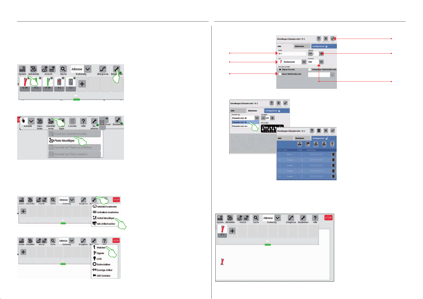
In der nun eingeblendeten Eingabemaske können alle Details der neuen Weiche eingestellt werden:
Fingertipp auf „Ok“ fügt
Weiche benennen.
Weichentyp auswählen.
Decoder auswählen.
Weitere Einstellmöglichkeiten erreichen Sie mit
Fingertipp auf den Reiter „Einrichten“. Hier wählen
Sie den Decoder-Typ und können die Schaltzeit
ändern, falls nötig.
die Weiche hinzu.
Adresse einstellen – falls sie
rot dargestellt wird, ist die
Adresse bereits vergeben.
Protokoll auswählen.
Die Registerkarte
„Konfigurieren“
ist für Experten
vorgesehen und
für den normalen
Betrieb nicht
relevant.
Weiche hinzufügen
Um eine neue Weiche anzulegen, tippen
Sie auf das Werkzeug-Symbol und öffnen
damit ein Aufklapp-Menü. Dort wählen
Sie „Artikel hinzufügen“.
Ein weiteres Aufklapp-Menü wird angezeigt. Dort wählen Sie „Weichen“.
Sobald Sie mit „Ok“ bestätigen, wird die neue Weiche in der Artikelliste angelegt. Gleichzeitig erscheint die
Weiche bereits auf der Platte (Bild unten).
Wichtig: Jeden neu hinzugefügten Artikel legt die CS3 automatisch auf derjenigen Platte ab, die
zum Zeitpunkt des Hinzufügens
aktiv ist. Achten Sie daher darauf,
welche Platte im Vordergrund ist.
16
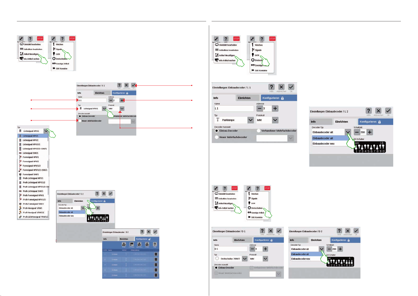
Signal hinzufügen
Licht hinzufügen
Für das Anlegen eines neuen Signalartikels tippen Sie in der Artikelliste auf das Werkzeug-Symbol und wählen im folgenden Aufklappmenü „Artikel hinzufügen“ (Bild links). Anschließend tippen Sie
auf „Signale“ (Bild rechts) und öffnen damit die Einstellungen (Bild
unten).
Hier können Sie die Details des neuen Signalartikels einstellen:
Signal benennen.
Signaltyp auswählen.
Decoder auswählen.
Den Signaltyp legen Sie mittels eines Aufklappmenüs fest, das Sie mit einem Fingertipp öffnen.
Dort stehen verschiedene Signalvarianten zur
Auswahl bereit.
Fingertipp auf „Ok“ fügt
das Signal hinzu.
Adresse einstellen – falls sie
rot dargestellt wird, ist die
Adresse bereits vergeben.
Protokoll auswählen.
Ein neuer Lichtartikel ist zügig angelegt: Mit Fingertipp auf das
Werkzeug-Symbol der Artikelliste („Bearbeiten“) öffnet sich
ein Aufklapp-Menü, in dem man „Artikel hinzufügen“ wählt. Im
folgenden Menü tippt man auf „Licht“ (Bilder links).
Nun können alle Einstellungen (Name, Adresse, Typ,
Protokoll, Decoder bzw. Decoder-Typ und Schaltzeit)
bearbeitet werden: in den Registerkarten „Info“
(Bild links) und „Einrichten“ (Bild unten).
Drehscheiben hinzufügen
Auch eine Drehscheibe ist im Handumdrehen in der Artikelliste: Mit
In der Registerkarte „Einrichten“ können Sie
weitere Einstellungen vornehmen. Hier wählen Sie
den Decoder-Typ und können zudem die Schaltzeit
ändern.
Die Registerkarte
„Konfigurieren“
ist für Experten
vorgesehen und
für den normalen
Betrieb nicht
relevant.
Fingertipp auf das Werkzeug-Symbol der Artikelliste („Bearbeiten“) öffnet
sich ein Aufklapp-Menü, in dem Sie „Artikel hinzufügen“ wählen (Bild
links). Im folgenden Menü tippen Sie auf „Drehscheiben“.
Nun haben Sie
Zugriff auf alle
Einstellungen in
den Registerkarten „Info“ (Name,
Adresse, Typ, Protokoll, Decoder; Bild
links) und „Einrichten“ (Decoder-Typ
und Schaltzeit; Bild
rechts).
17
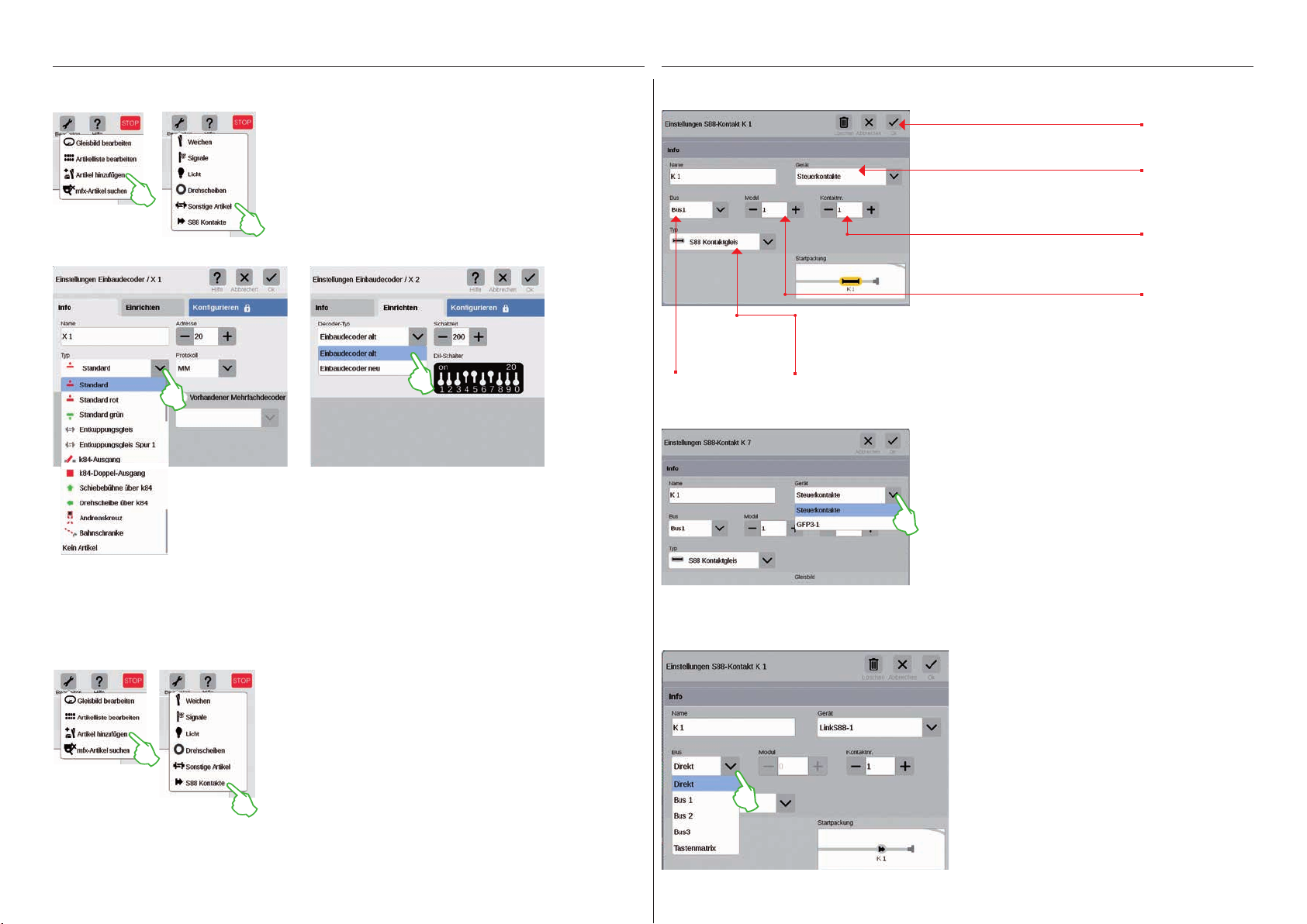
Sonstige Artikel hinzufügen
Nun sind Sie im Einstellungen-Menü. Hier stellen Sie die Details des neuen S88-Kontakts ein:
Verschiedenste Artikel lassen sich über diese Option
hinzufügen: Auf das Werkzeug-Symbol der Artikelliste
tippen und im Aufklapp-Menü „Artikel hinzufügen“
(Bild links) wählen sowie im Anschluss „Sonstige
Artikel“.
Im Feld „Typ“ stellen Sie den konkreten Artikeltyp ein (Bild links)
und passen die übrigen Felder – in den Registerkarten „Info“ und
„Einrichten“ – nach Ihrem Bedarf an.
Auswahl des
genutzten
Märklin Busses.
Anschlussweg des Rückmeldekontakts:
Auswahl der Art des Rückmeldekontakts (siehe unten).
Fingertipp auf „Ok“ fügt
den Kontakt hinzu.
Auswahl des Geräts, an dem der Kontakt
angeschlossen ist (siehe unten).
Kontaktnummer auf
dem S88-Modul.
Nummer des ver-
wendeten S88-Moduls.
Im Ausklapp-Menü „Gerät“ stellen Sie das Gerät ein, an dem
Sie den Rückmeldekontakt angeschlossen haben.
Bei der CS3 plus finden Sie hier die Option „GFP3-1“, die dem
S88-Anschluss an der Geräteunterseite entspricht (Bild links).
Bei der CS3 (60226) sind Rückmeldemodule über den Link S88
anzuschließen (siehe unten).
Bus- und Moduleingabe bei Verwendung des Link S88:
S88-Kontakte hinzufügen
S88-Kontakte erweitern die Steuerungsmöglichkeiten enorm.
Um sie der Artikelliste hinzuzufügen, tippen Sie auf das
Werkzeug-Symbol der Artikelliste („Bearbeiten“) und im Aufklapp-Menü auf „Artikel hinzufügen“ (Bild links).
Im folgenden Menü wählen Sie „S88-Kontakte“.
Beim Einsatz des Link S88 können Sie Rückmeldekontakte auf folgenden Wegen anschließen:
- direkt am Link S88
- an weiteren S88-Modulen, die am Link S88 angeschlossen sind (über Bus 1, Bus 2 oder Bus 3)
- über eine Tastenmatrix (siehe Seite 19)
Je Kontakt wählen Sie die Anschlussart (Bus) und
geben die Nummer des S88-Moduls (1-32) und die
Nummer des Schaltkontakts am Modul ein.
Bei der Anschlussart „Direkt“ reicht es aus, die Nummer des Schaltkontakts am Link S88 einzutragen.
18
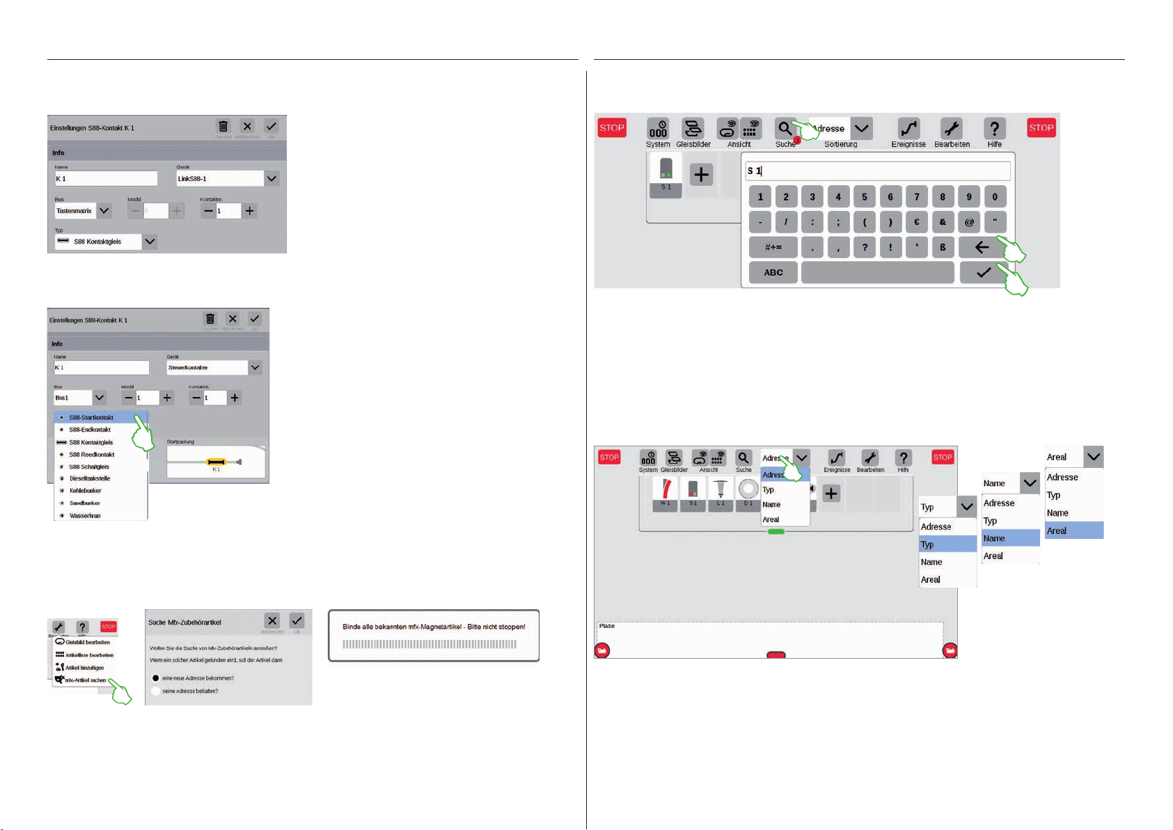
Tastenmatrix:
Art des S88-Rückmeldekontakts auswählen:
Sie können den Link S88 für eine Tastenmatrix,
beispielsweise für ein Gleisstellpult verwenden.
Bis zu 64 Tasten (32 Magnetartikel oder 64 Fahrstraßen) werden unterstützt. Die zugehörigen
Schaltpunkte geben Sie im Feld „Kontaktnr.“ ein.
Im Ausklapp-Menü „Typ“ wählen Sie den Typ des
verbauten Rückmeldekontakts aus: Kontaktgleis,
Reedkontakt oder Schaltgleis.
Für den mfx+-Spieleweltmodus stehen weitere
Kontaktarten wie Dieseltankstelle, Kohlebunker, Sandbunker und Wasserkran zur Auswahl bereit.
Magnetartikel suchen / Live-Suche
Mit der Suchfunktion suchen Sie gezielt nach dem Namen oder dem Teil des Namens einzelner oder
mehrerer Magnetartikel. Tippen Sie auf das Lupensymbol („Suche“) und geben Sie auf der eingeblendeten Tastatur den Suchbegriff ein. Die CS3 sucht jeweils direkt nach der Eingabe jedes Zeichens (Live-Suche). Ein kleiner roter Punkt weist auf die aktive Suche hin, die darin abgebildete Zahl
entspricht der Anzahl der eingegebenen Zeichen. Den Suchmodus beenden Sie durch das Löschen
des Suchbegriffs mit der Rücktaste. Tippen Sie auf den Bestätigungshaken auf der Tastatur, um sie
auszublenden.
Magnetartikel sortieren
mfx-Artikel suchen
In seltenen Fällen kann es vorkommen, dass in der Artikelliste ein angelegter Artikel nicht mehr angezeigt wird. Diese Funktion dient dazu, ihn wieder aufzufinden.
Mit dem Aufklappmenü am oberen Rand der Artikelliste sortieren Sie die Magnetartikel nach verschiedenen
Kriterien: Nach vergebener Adresse, der jeweiligen Artikelbezeichnung („Namen“), dem Artikel-Typ oder der
Zugehörigkeit zu einem Areal.
Die Funktion starten Sie, indem Sie auf das Werkzeug-Symbol der Artikelliste („Bearbeiten“) und im
Aufklapp-Menü auf „mfx-Artikel suchen“ tippen (Bild links). Daraufhin fragt die CS3, ob die gefundenen
Artikel ihre Adresse behalten oder ob sie eine neue Adresse bekommen sollen (Bild Mitte). Bestätigen
Sie Ihre Auswahl mit „Ok“. Nun informiert die CS3 mit verschiedenen Einblendungen über ihren Arbeitsfortschritt (Bild rechts).
19
Gleisstellbild bearbeiten
Gleisartikel positionieren . drehen . verbinden
20
Gleisstellbild aufbauen
In diesem Abschnitt lernen Sie alle nötigen Schritte kennen, die für den Aufbau eines Gleisstellbilds in
der Central Station 3 nötig sind. Als Beispiel dient das einfache Gleisbild der Märklin Startpackung (siehe
Seite 24), das wir auf den folgenden Seiten Schritt für Schritt modellieren.
Platte hinzufügen
Mit einer Platte erstellen Sie die Grundlage für das Gleisstellbild. Aktivieren Sie zunächst den Bearbeitungsmodus, indem Sie rechts oben auf das Werkzeug-Symbol („Bearbeiten“) tippen und anschließend
„Gleisbild bearbeiten“ wählen. In der nun eingeblendeten Symbolleiste tippen Sie auf „Gleisbild/Areal“
und im Ausklappmenü auf „Platte hinzufügen“. Tipp: Die Symbolleiste können Sie verschieben, wenn Sie
das 9-Punkte-Symbol an deren rechtem Ende mit dem Finger an die Zielposition ziehen.
Im eingeblendeten Dialogfeld geben Sie der neuen Platte einen
Namen und bestätigen mit „Ok“.
Wichtig: Wählen Sie die Bezeichnung bewusst. Der Name der
Platte kann nachträglich nicht geändert werden.
Größe der Platte ändern
Mithilfe der kleinen schwarzen Kreise, die an jeder Plattenseite zu sehen
sind, lässt sich die Platte vergrößern
oder verkleinern.
Um die Platte nun auf Displaygröße
aufzuziehen, tippen Sie auf einen der
Kreise, halten den Finger auf dem
Display und ziehen den Finger an
den Bildschirmrand. Wiederholen
Sie dies für die anderen drei Seiten.
Fertig! Nun haben Sie ausreichend
Raum, um das auf den Folgeseiten
beschriebene einfache Gleisbild
(siehe Seite 24) aufzubauen.
Magnetartikel aus der Artikelliste auf die Platte ziehen
Ziehen Sie nun die benötigten Magnetartikel aus der Artikelliste auf die
angelegte Platte: die Weichen W1R,
W2L und W3R sowie die Signale S1 und
S2. Dazu berühren Sie das jeweilige
Symbol, ziehen den Finger in die Mitte
des Displays und lösen ihn wieder vom
Bildschirm. Wichtig: Der Gleisbild-Bearbeitungsmodus muss für diese
Schritte weiterhin aktiviert sein.
Platte löschen
Und schon ist die neue Platte angelegt, hier im Beispiel mit dem Namen
„Basis anlage“. Mit Fingertipp auf
das Mülleimersymbol in der Mitte
der Platte lässt sich diese wieder
löschen – so lange sie leer und der
Bearbeitungsmodus aktiv ist. Ihn
erkennen Sie an zwei Merkmalen:
an den hellgrauen Pluszeichen, mit
denen die Platte hinterlegt ist und
anhand des grünen Kreises mit Haken am Fuß des Werkzeug-Symbols.
Magnetartikel auf der Platte verschieben
Im geplanten Gleisbild (siehe Seite
24) hat die Weiche W1R ihren Platz
im linken oberen Abschnitt der Platte.
Ziehen Sie daher die Weiche in diesen
Bereich, indem Sie das Weichen symbol
berühren und den Finger auf dem
Display nach oben ziehen.
Der hellblaue Kreis um die Weiche zeigt
an, dass Sie die Weiche durch das
Antippen ausgewählt haben.
21

Magnetartikel drehen: Der Drehmodus
Hinzufügen von Gleisbauartikeln
Für das geplante Gleisstellbild benötigen
wir die Weiche in horizontaler Ausrichtung.
Daher drehen wir sie um 90 Grad: Zunächst
markieren wir die Weiche, indem wir sie
kurz antippen. Sie sehen wieder den hellblauen Kreis, der die Weiche umgibt. Dann
tippen wir nochmals, lassen den Finger
aber auf dem Display. Der Doppelpfeil am
Rand der Weiche wird nun blau umrandet
dargestellt (Bild links).
Die Weiche befindet sich nun im Drehmodus.
Sie können auf dem Display an beliebiger
Stelle mit dem Finger auf- und abfahren – sobald Sie allerdings den Finger vom Display lösen, endet der Drehmodus. Die Weiche dreht
sich entsprechend ihrer Fingerbewegung,
parallel dazu wird auf dem Weichensymbol
der aktuelle Winkel angezeigt. Stoppen Sie
bei 90 Grad.
Tipp: Je weiter Sie Ihren Finger von der
Weiche entfernen, desto langsamer erfolgt
die Drehung: Der Zielwinkel lässt sich so
einfacher einstellen.
Um ein optisch ansprechendes Gleisbild zu erstellen,
benötigen wir Gleisverlauf-Artikel. Das sind reine Gestaltungselemente ohne weitere Funktion. Mittels der
„Hinzufügen“-Schaltfläche in der Symbolleiste öffnen Sie
ein Aufklappmenü, in dem Sie „Gleisbau Artikel“ wählen.
Im folgenden Menü tippen Sie viermal auf „Gleisverlauf“
und einmal auf „Prellbock“, da auch ein Abstellgleis Teil
des Ziel-Gleisbildes ist. Zum Schließen des Menüs tippen
Sie nochmals auf „Hinzufügen“ oder auf einen Bereich
außerhalb des Menüs.
Tipp: Nach demselben Prinzip fügen Sie andere mögliche
Gleisbauartikel wie Tunnel, Brückenwiderstände und
Brücken hinzu (Bild links). Auch alle weiteren Artikel von
Weichen bis zu S88-Kontakten lassen sich auf diesem Weg
hinzufügen und gleichzeitig in der Artikelliste anlegen.
Die Gleisverlauf-Artikel
und der Prellbock werden
durch das Hinzufügen
automatisch auf der aktivierten Platte abgelegt,
in unserem Fall auf der
„Basisanlage“.
Um dem Ziel-Gleisbild
näher zu kommen, benötigen wir die Weiche „W 2L“
im linken unteren Abschnitt
der Platte. Dafür braucht
es dieselben Schritte wie
oben beschrieben: Ziehen
Sie also die Weiche in den
linken unteren Plattenabschnitt (Bild links), aktivieren Sie den Drehmodus und
drehen Sie die Weiche in
die Waagrechte, entsprechend einem angezeigten
Winkel von 90 Grad (Bild
rechts).
Die hinzugefügten Artikel erscheinen
auf der Platte stets in einer festgelegten Ausrichtung. Da wir für den
nächsten Schritt einen waagerechten Gleisverlauf-Artikel benötigen,
müssen wir ihn neu ausrichten und in
die Waagrechte drehen (Drehmodus
siehe linke Seitenhälfte).
22
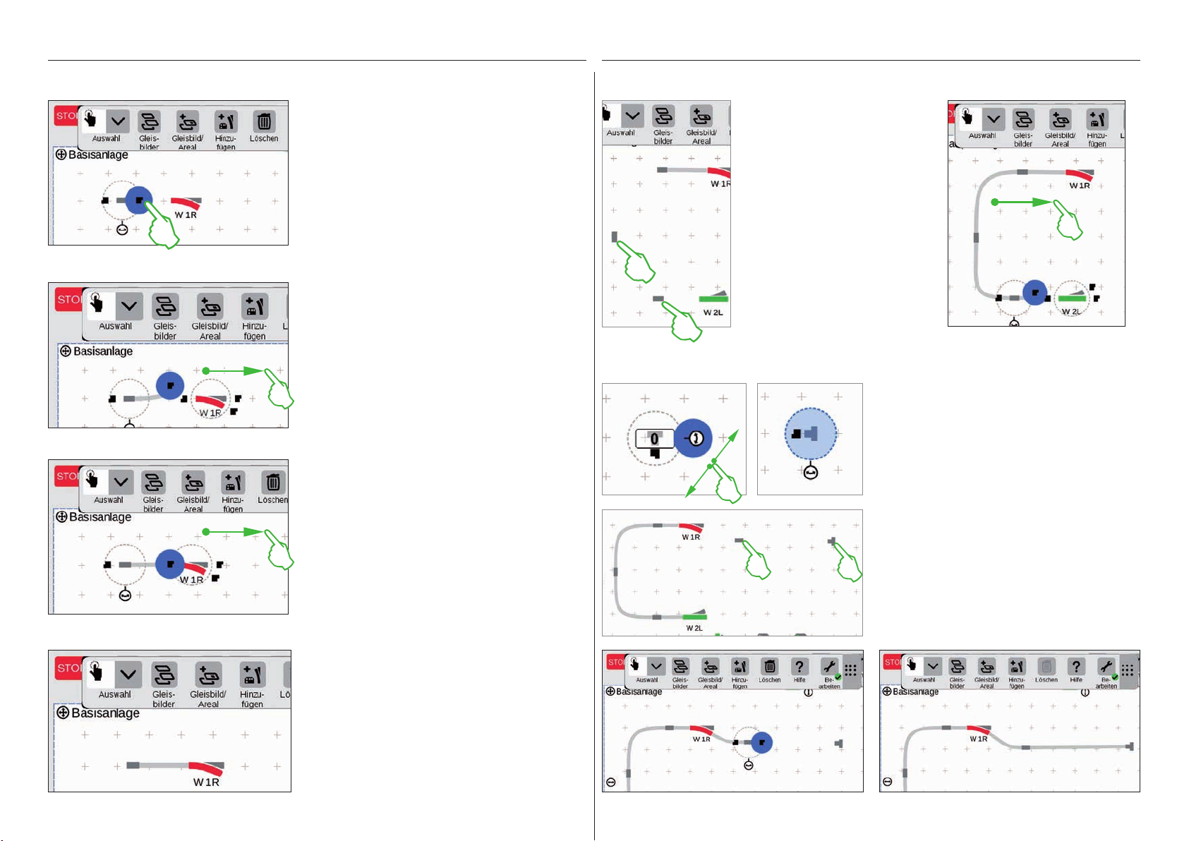
Artikel verbinden: Der Verbindungsmodus
Ziehen Sie den nun waagerechten Gleisverlauf-Artikel links neben die Weiche „W 1R“. Am
Rand des markierten Gleisverlauf-Artikels sehen
Sie links und rechts zwei schwarze Symbole. Sie
sind die Andockstellen, mittels derer zwei Artikel
miteinander verbunden werden.
Nun tippen Sie auf das rechte Symbol, das
dadurch blau markiert wird: Sie haben den
Verbindungsmodus aktiviert (Bild links).
Ziehen Sie dieses blau markierte Verbindungssymbol in Richtung Weiche (Bild links).
Tipp: Sie können die Zieh-Bewegung mit dem
Finger an beliebiger Stelle auf dem Display
ausführen. So haben Sie perfekte Sicht auf die
zu verbindenden Artikel.
Sobald die beiden Andockstellen sich überlappen, lösen Sie den Finger vom Display. Die
Central Station 3 stellt automatisch eine Gleisverbindung zwischen den Verbindungsstellen
her (Bild links).
Nun gibt es gleich die Gelegenheit,
das Verbinden weiter zu üben: Stellen
Sie die Verbindung zu der auf der
vorherigen Seite bereits positionierten
Weiche „W 2L“ her. Dazu platzieren
Sie zwei der bereits hinzugefügten
Gleisverlaufs-Artikel wie abgebildet
(Bild links). Einmal ist eine Drehung um
90 Grad erforderlich (siehe „Drehmodus“ auf Seite 22).
Schließlich verbinden Sie die Artikel,
indem Sie jeweils zunächst eine Andockstelle in den Verbindungsmodus
schalten (Bild rechts) und dann die
Verbindung herstellen (siehe „Verbindungsmodus“ am Beginn dieser Seite).
Weiche und Prellbock verbinden
Nun wird ein Abstellgleis an die obere
Weiche angebunden. Dazu rotieren
Sie zunächst den Prellbock und einen
Gleisverlaufs-Artikel in einen Winkel von 90 Grad (Bilder links; siehe
„Drehmodus“ auf Seite 22).
Nun werden beide Gleisbauartikel wie
nebenstehend abgebildet positioniert.
Danach wird die Weiche mit dem
Gleisverlauf-Artikel verbunden (siehe
„Verbindungsmodus“ am Beginn dieser
Seite). Anschließend stellen Sie die
Verbindung zwischen Gleisverlauf-Artikel und Prellbock her (Bilder unten).
Tippen Sie neben Weiche und Gleisverlauf-Artikel auf die Platte, so werden sämtliche Markierungen entfernt. Sie sehen nur die Artikel samt
Gleisverbindung (Bild links).
Herzlichen Glückwunsch, Sie haben Ihr erstes
Artikelpaar verbunden!
Tipp: Alternativ können Sie Artikel verbinden,
indem Sie diese nah beieinander platzieren.
23

Gleisstellbild vervollständigen
Signale einfügen
Nun folgen die Signale: Zunächst ziehen wir die Signale in Position: Sobald sie sich über dem richtigen
Gleisabschnitt befinden, lösen Sie den Finger vom Display. Das Signal dockt jeweils automatisch an das
Gleis an.
Die Hälfte des Gleisbildes steht bereits. Nun folgt
der Bahnhof und der Rest des Ovals: Wir ziehen die
Weiche „W 3R“ in den rechten unteren Abschnitt der
Platte und drehen sie in die Waagrechte (Bild links
oben), aktivieren an der Weiche „W 2L“ den Verbindungsmodus (Bild rechts oben) und verbinden sie mit
der rechten Weiche (Bild links).
Nun wird im Bahnhof noch ein zweites Gleis eingezogen und das Oval geschlossen. Dazu fügen wir fünf
weitere Gleisverlauf-Artikel hinzu, positionieren sie wie unten abgebildet und drehen sie nach Bedarf in
die passende Ausrichtung (Bild links unten). Schließlich werden Weichen und Gleisverlauf-Artikel miteinander verbunden.
Falls notwendig, kann die Ausrichtung des Signals von Hand angepasst werden. Dazu wird jeweils der
Drehmodus aktiviert und anschließend der Winkel eingestellt.
Gleisstellbild fertiggestellt
Zum Abschluss beenden Sie
den Bearbeitungsmodus,
in dem Sie auf das Werkzeugsymbol tippen. Dadurch
werden die Gleisverlauf-Artikel ausgeblendet (Bild links).
Gratulation, Sie haben Ihr
erstes Gleisbild erstellt! Sicherlich haben Sie bemerkt,
dass das Bearbeiten des
Gleis bildes mit jedem weiteren Mal ein wenig einfacher
von der Hand geht.
24
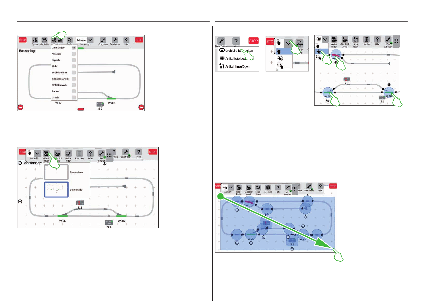
Ansichtsoptionen
Tippen Sie auf die Schaltfläche „Ansicht“ in der
oberen Symbolleiste, um
zahlreiche Filteroptionen
angezeigt zu bekommen. In
der Standardeinstellung ist
die Option „Alles zeigen“
markiert. Mit Fingertipp auf
die einzelnen Artikel-Kategorien können Sie sich
einen hervorragenden
Überblick auf Ihrer Platte
verschaffen.
Auswahl einzelner und mehrerer Artikel
Für verschiedene Aktionen ist es notwendig, zuvor
einen oder mehrere Artikel auszuwählen. Erster
Schritt dafür ist stets, den Bearbeitungsmodus zu
aktivieren, indem Sie auf das Werkzeugsymbol
in der oberen Symbolleiste tippen und „Gleisbild
bearbeiten“ wählen (Bild links oben).
Einzelne Artikel wählen Sie aus, indem Sie sie kurz antippen: Ein hellblauer Kreis signalisiert die
Auswahl, der Doppelpfeil für den Drehmodus und die Andockstellen für den Verbindungsmodus werden
sichtbar. Im Aufklappmenü „Auswahl“ links oben in der Bearbeitungs-Symbolleiste ist diese Option
voreingestellt (mittleres Bild oben).
Aktive Platte wechseln
Sobald Sie Gleisstellbilder auf mehreren Platten verwalten, ist die Schaltfläche
„Gleisbilder“ sehr nützlich, um zwischen den Gleisstellbildern hin- und herzuschalten.
Um die aktive Platte zu wechseln, tippen Sie auf die Schaltfläche „Gleisbilder“
und anschließend auf die gewünschte Platte: Die neue Platte ist nun im Vordergrund.
Tippen Sie doppelt auf die aktive Platte, um sie vollständig anzuzeigen.
Mehrere Artikel wählen Sie aus, indem Sie in der Bearbeitungs-Symbolleiste links oben auf die Schalt-
fläche „Auswahl“ tippen und im Aufklappmenü die zweite Option wählen, die umkreiste Hand. Anschlie-
ßend tippen Sie der Reihe nach auf alle Objekte, die Sie in die Auswahl einschließen möchten (Bild oben
rechts).
Flächenauswahl
Eine ganze Platte oder einen beliebigen Ausschnitt davon können Sie mit
der Flächenauswahl markieren.
Dazu tippen Sie auf die „Auswahl“Schaltfläche links oben in der Bearbeitungs-Symbolleiste. Im Aufklappmenü
wählen Sie die unterste Option, die
mit einem Quadrat dargestellt ist. Nun
tippen Sie auf einen Eckpunkt der
Fläche, die Sie auswählen möchten,
ziehen den Finger zum gegenüberliegenden Eckpunkt und lösen den Finger
vom Display.
25
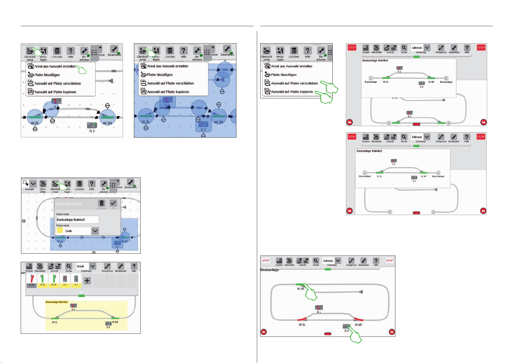
Areal aus Auswahl erstellen
Sobald Sie mehrere Artikel (Bild links) oder eine Fläche (Bild rechts) ausgewählt haben, wie auf der
vorherigen Seite beschrieben, sind im Aufklappmenü der Schaltfläche „Gleisbild/Areal“ weitere, zuvor
ausgegraute Optionen aktivierbar: „Areal aus Auswahl erstellen“, „Auswahl auf Platte verschieben“ und
„Auswahl auf Platte kopieren“.
Um ein Areal zu erstellen, müssen Sie eine
Fläche ausgewählt haben. In diesem Beispiel
erstellen wir aus dem flächig ausgewählten
Bahnhof (siehe Bild links) ein Areal. Dazu
öffnen Sie mit Fingertipp auf die Schaltfläche
„Gleisbild/Areal“ das entsprechende Aufklappmenü und wählen dort „Areal aus Auswahl
erstellen“. In der eingeblendeten Eingabemaske geben Sie dem Areal einen Namen, wählen
seine Farbe und bestätigen mit „Ok“.
Auswahl auf Platte verschieben und kopieren
Größere Übersicht gerade bei
komplexeren Anlagen errei-
chen Sie mit der Funktion, eine
Auswahl auf eine neue Platte zu
kopieren (Bild rechts oben) oder
zu verschieben (Bild rechts). Die
neue Platte wurde „Basisanlage
Bahnhof“ genannt.
Ihre Anlage wird damit auf zwei
Platten verteilt, bleibt allerdings
logisch miteinander verknüpft
– an der Funktion ändert sich
nichts. Die Übergänge zwischen
beiden Platten werden hier
durch die beiden Zahlen „1“ und
„2“ symbolisiert.
Weichen und Signale schalten
Auf Ihren Gleisstellbildern könDaraufhin wird der ausgewählte Ausschnitt
dauerhaft in der gewählten Farbe markiert.
Auch in der Artikelliste lassen sich anhand der
Farbe alle Artikel eines Areals leicht erkennen.
Das Löschen eines Areals ist ebenfalls sehr
einfach: Im aktivierten Gleisbild-Bearbeitungsmodus tippen Sie auf den Arealnamen in der
linken oberen Ecke des Areals. Im daraufhin
eingeblendeten Fenster wählen Sie die Option
„Löschen“.
nen Sie sämtliche Magnetartikel
wie Weichen oder Signale direkt
schalten: Tippen Sie einfach auf
das jeweilige Symbol.
Tipp: Achten Sie darauf, dass
die STOP-Taste nicht aktiviert
ist. Zum Schalten müssen die
Gleise mit Strom versorgt sein.
26
Ereignisse erstellen und bearbeiten
Fahrstraßen anlegen . Abläufe programmieren und schalten
27
Ereignisse hinzufügen | Automatisieren von Abläufen
So einfach starten Sie die Programmierung
Die Automatisierung von Abläufen ist für viele Modelleisenbahner die Krönung ihres Hobbys. Mit der
Central Station 3 wird das Anlegen von Fahrstraßen, Lokabläufen und die automatische Steuerung
gesamter Anlagen nochmals deutlich vereinfacht. Dank Drag & Drop müssen die einzelnen Elemente nur
mehr in die Ablaufleiste gezogen werden. Auch die Kontrolle ist deutlich einfacher.
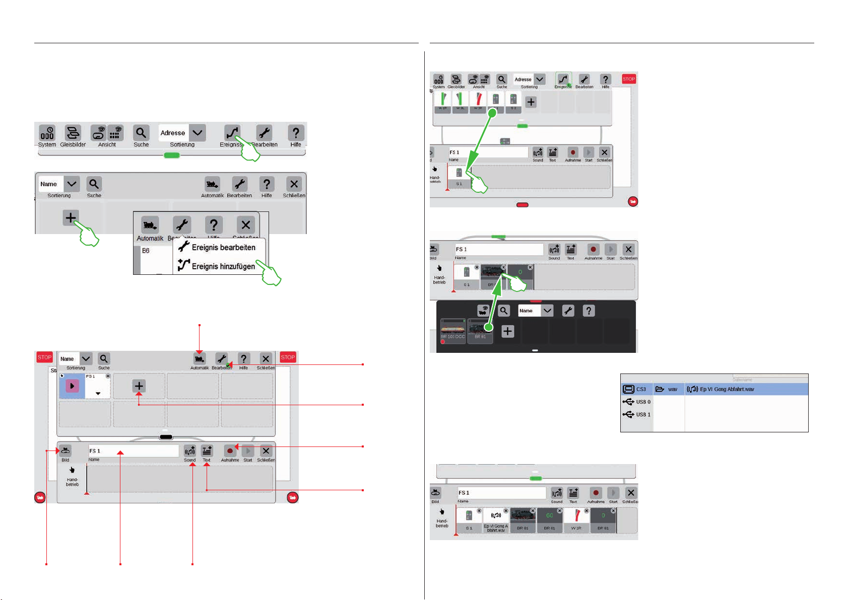
Um Abläufe neu anzulegen oder vorhandene
zu bearbeiten, tippen Sie
auf den Button „Ereignisse“. Analog den Themen
Lok und Artikel öffnet
sich ebenfalls eine Liste.
Sollten noch keine Abläufe programmiert sein,
befindet sich im ersten
Quadrat ein „+“-Zeichen.
Einen neuen Ablauf fügen
Sie über das „+“-Zeichen
hinzu oder über den
Menüpunkt „Bearbeiten“,
„Ereignis hinzufügen“.
Das Hauptmenü zur Ablaufsteuerung im Überblick
Hier können Sie die Automatik
vorübergehend ausschalten.
Fahrstraßen aufbauen: Schritt für Schritt
Nach dem Öffnen des Menüpunkts „Ereignis hinzufügen“ einfach die entsprechenden Artikel in die Zeitleiste ziehen
– zum Beispiel Signal 1. Schritt für Schritt
lässt sich so die Fahrstraße aufbauen.
Beim Antippen der Artikel – zum Beispiel
von Signal 1 – öffnet sich automatisch die
Menüleiste, um die gewünschte Funktion
einzustellen.
Lokomotiven einbinden
Analog zu den Magnetartikeln kann aus
der Lokliste das gewünschte Fahrzeug
ebenfalls in die Zeitleiste gezogen
werden.
Jeder Ablauf
kann optisch mit
einem Foto unterlegt werden.
Individuelle Vergabe von Namen
für Fahrstraßen,
Abläufe etc.
Möglichkeit, um
Sounddateien
einfach zu integrieren.
Button um Ereignisse
neu anzulegen oder zu
bearbeiten.
Über „+“ starten Sie die
Eingabe für einen neuen
Ablauf.
Alternative zur manuellen
Eingabe: die Abläufe im
Betrieb aufzeichnen.
Dient der Eingabe von
Informationen, wenn Sie
nach Fahrplan fahren
wollen.
Über den Button „Sound“ lassen sich an jeder
Stelle des Ablaufs Sounddateien integrieren.
Die Dateien können entweder auf der CS3 liegen oder über den USB-Stick importiert werden
(Bild rechts).
Kleine Fahrstrecke finalisieren
Schritt für Schritt lässt sich die Fahrstraße einfach per Drag & Drop zusammenstellen. Jeder einzelne Punkt (Geschwindigkeit, Signal- und Weichenstellungen
etc.) kann dabei individuell angepasst
werden (siehe folgende Seiten).
28
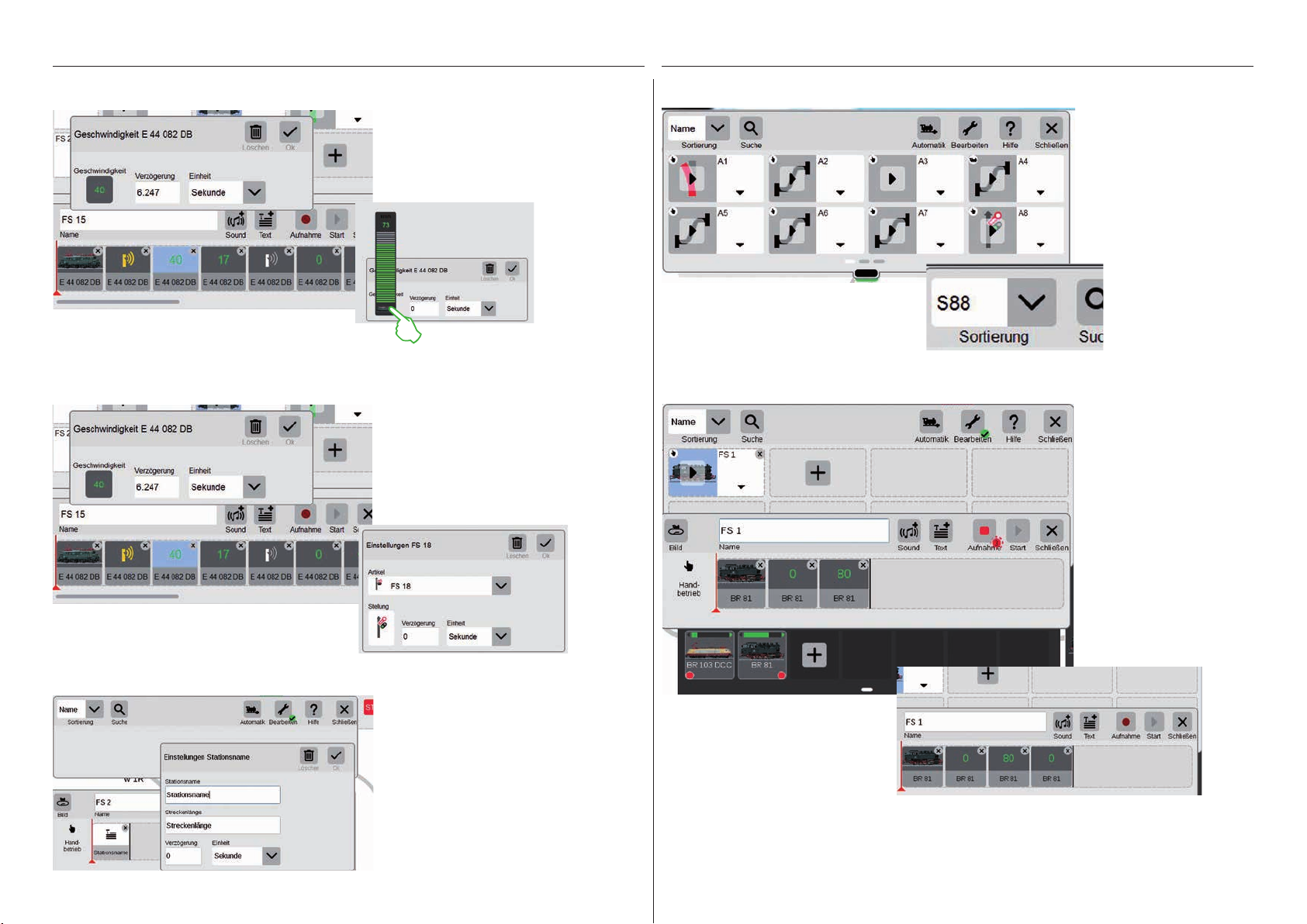
Die Geschwindigkeit einer Lok lässt sich über den grünen
Geschwindigkeitsbalken justieren.
So funktioniert die Anpassung von Einstellungen: Den Punkt „Ereignis bearbeiten“
aufrufen und den entsprechenden Ablauf
antippen. Das Ereignis wechselt in den
Bearbeitungsmodus, erkennbar an kleinen
Kreuzen in den Quadraten oben rechts.
Sortieren der EreignisseEinstellungen bearbeiten / Geschwindigkeit
Überblick: Alle erstellten Fahrstraßen und Abläufe lassen
sich ganz einfach nach Name
oder den Rückmeldekontakten
(S88) sortieren. Tippen Sie
einfach auf das Aufklappmenü
in der linken oberen Ecke des
Fensters.
Die Sortierung nach Rückmeldekontakten bietet sich dann an, wenn es darum geht, schnell
einen Überblick über die einzelnen Besetztmeldungen zu erhalten.
Zeitangaben / Verzögerungen eingeben
Textinformationen hinzufügen
Um Abläufe zeitlich exakt aufeinander
abzustimmen, gibt es die Möglichkeit, im
Feld Verzögerung die entsprechenden
Zeiteinheiten einzugeben. Die Verzögerung gibt dabei an, wann das nächste
Ereignis ausgelöst werden soll.
Mit dem Punkt „Text“ steht eine Komponente zur Verfügung, um Informationen
einzugeben, wenn nach Fahrplan gefahren werden soll.
Aufnahmefunktion benutzen
Parallel zur manuellen Eingabe
besteht auch bei der CS3 die
Möglichkeit, über eine Aufnahmefunktion Fahrstraßen und
Abläufe zu erfassen. Ähnlich
wie eine Videokamera zeichnet
die CS3 dabei einen Ablauf auf
und gibt ihn später wieder.
Wichtig: Beim Programmieren
über die Aufnahmefunktion
darf nur die gewünschte Fahrstraße geschaltet werden.
Manuelle Aufnahme: Lok aufsetzen, Aufnahme-Button drücken, losfahren. Ein roter
Punkt signalisiert die laufende Aufnahme.
Am Ende der Fahrt Lokomotive abstellen
und Aufnahme beenden (wiederum auf
Button tippen). Nach der Aufnahme kann
jedes Ablaufelement einzeln nachbearbeitet
werden (Bild rechts).
29

Weichenstraßen anlegen
Lokabläufe programmieren
So einfach wie noch nie
lassen sich mit der CS3
Weichenstraßen anlegen: die
einzelnen Weichen aus der
Artikelliste in die Zeitachse
ziehen und die Fahrstraße
steht.
Über das Menü „Bearbeiten“
lassen sich alle einzelnen
Weichen individuell einstellen
(Bild ganz links). Über den
„Start“-Button kann die
Fahrstraße überprüft werden
– im Feld der Fahrstraße
erscheint ein grüner Punkt. Er
gibt zusätzlich den aktuellen
Stand der Ablaufsteuerung
wieder.
Auch Lokabläufe lassen
sich ganz bequem mit
der CS3 programmieren:
Lok auswählen und die
verschiedenen Funktionen
wie „Betriebsgeräusch an“,
„Ansage an“ oder „Licht an“
aus den Funktionselementen
übernehmen.
Ablaufsteuerung über Rückmeldekontakte
Sollen Kontakte als Auslöser für Fahrstraßen oder automatisierte Abläufe verwendet werden, kann man ganz einfach
wie folgt vorgehen: werden: Kontakt in
das Feld am linken Rand der Fahrstraße ziehen – z.B. K1 (Bild oben). Dann
dieses Kontakt-Symbol antippen und die
Bedingungen definieren – z. B. „Einfahrend“ (Bild rechts). Der gesamte Ablauf
wird dann geschaltet, wenn der Kontakt
1 eine Belegung meldet. Im Ablauf selbst
können wiederum weitere Rückmeldekontakte aufgenommen werden (z.B.
S88-2, Bild oben), indem man sie in die
Zeitleiste zieht.
Ablaufsteuerung mit bedingter Ausführung
Durch das Antippen der
Icons kann jede einzelne
Funktion individuell eingestellt werden (Bilder unten).
Über den Button „Start“
kann der gesamte Ablauf
abgespielt/kontrolliert
werden.
Auch das Verknüpfen ganzer Fahrstraßen
und Abläufe meistert die CS3 ohne Weiteres. Dazu über „Bearbeiten“ ein neues
Ereignis erstellen und die entsprechenden
Icons der Abläufe in die Zeitleiste ziehen.
Jedes einzelne Ereignis lässt sich dabei
über das Menü „Bearbeiten“ wieder individuell anpassen.
30

Systemeinstellungen
Anpassung des Systems · Systeminformationen
31

Systemeinstellungen aufrufen und ändern
Aufruf des System-Menüs
Auf die Einstiegsseite der Systemeinstellungen (Bild
rechts) gelangen Sie, indem Sie in der Symbolleiste der
Artikelliste links oben auf die Schaltfläche „System“
tippen (siehe auch Seite 6).
Auf der Einstiegsseite öffnen Sie mit Fingertipp jeweils
die Einstellungen bzw. eine detailliertere Ansicht.
Übersicht der angeschlossenen Geräte.
Optionen zum Verhalten von
Loks und Magnetartikeln.
Einstellungen der Central Station 3.
Master-Slave-Optionen.
Nennt die Versionsnummern
von Hard- und Software.
Netzwerk: Übersicht über alle aktiven Komponenten
IP-Einstellungen, falls ein
LAN-Kabel angeschlossen ist.
Zugriff auf Basisfunktionen der Central Station 3
Um die CS3-Systemeinstellungen zu öffnen, tippen Sie in der Netzwerkübersicht oder in der Menüspalte am
linken Rand auf das CS3-Symbol. Die unteren Seitenabschnitte erreichen Sie, indem Sie mit dem Finger in der
Displaymitte nach oben wischen.
Der sichere und
empfohlene Weg, die
CS3 auszuschalten.
Erstellt eine Sicherung ihrer aktuellen CS3-Daten.
Tipp: Nutzen Sie diese Funktion regelmäßig, um Bearbeitungsstände zu sichern – am besten auch mittels USB-Sticks.
Setzt die CS3 mithilfe einer zuvor erstellten
Sicherungsdatei auf einen früheren Bearbeitungsstand zurück (siehe auch Seite 6).
Fährt die CS3 herunter
und startet neu.
Neustart der internen Anwendungen
wie z. B. der Benutzeroberfläche.
Sprache der Bedienungsoberfläche ändern.
Mit Schieberegler
Bildschirmhelligkeit bzw.
Lautstärke anpassen.
Wahl zwischen eingebautem
und externem Lautsprecher.
Nur relevant im Fall eines
unvollständigen CS3-Updates.
Mit gesetztem Haken prüft die
CS3 regelmäßig, ob ein FirmwareUpdate verfügbar ist.
Spontansteuerung in der Lokliste
an- und abschalten.
Die Netzwerkübersicht informiert über alle angeschlossenen und aktiven Geräte. Deren Einstellungen erreichen
Sie per Fingertipp direkt in der Übersicht oder über die
Menüspalte am linken Rand. Mit Fingerwisch nach oben
gelangen Sie zu den unteren Abschnitten der Seite (Bild
rechts). Inaktive Geräte werden ausgegraut dargestellt.
Aktiviert Sprachauswahl- Dialog
und Einrichtungs assistenten bei
CS3-Start (siehe auch Seite 3).
Berühren Sie die „Zurück“-Schaltfläche links oben, um jederzeit wieder auf die Einstiegsseite der Systemeinstellungen zu gelangen. Die weiteren in der linken Menüspalte aufgeführten Optionen erreichen Sie ebenfalls
mit einfachem Fingertipp.
Die weiteren Abschnitte „Gleis“, „IP“, „Master-Slave“ und
„Info“ werden auf der nächsten Seite erläutert. Sie öffnen
Sie, indem Sie jeweils auf den Pfeil am linken Rand tippen.
32

Gleis-Einstellungen aufrufen
Hier können Sie nicht
benutzte Proto kolle
abschalten.
Setzt nach einem Neustart alle
Loks automatisch auf den letzten
bekannten Status.
Im Aufklappmenü legen Sie
die Belegung der Drehregler
im Spielewelt-Modus fest.
GFP3 – Daten
Über GFP3 (Gleis Format Prozessor 3) erhalten Sie Auskunft über aktuelle Messdaten der Anlage und der CS3.
Mit einem Fingerwisch nach oben gelangen Sie zu den unteren Seitenabschnitten, inklusive der Einstellungen
(Bilder unten).
IP-Einstellungen einsehen
Master-Slave-Einstellungen
Info-Abschnitt
Diese Option steht zur Verfügung, wenn Sie
Ihre Central Station 3 per LAN-Kabel mit Ihrem
Router verbinden. Sie haben hier die Wahl, ob
sich die CS3 die notwendigen Netzwerkadressen automatisch vom Router besorgen soll oder
ob Sie die Daten von Hand eintragen.
Sobald mehr als eine CS3 bzw. CS3 plus
eingesetzt werden, bekommt dieser Abschnitt
Bedeutung: Hier stellen Sie ein, welche CS3 das
Hauptgerät (Master) und ob dieses Gerät ein
Zweitgerät ist.
Im Info-Abschnitt sind die Hardware- und
Softwareversionen Ihrer CS3 sowie rechtliche
Informationen aufgeführt.
Festlegung der Zeitspanne,
nach der die Messwerte
erneut erfasst werden.
GFP3 – Einstellungen
S88Bus: Länge, Zykluszeit
und Bitzeit einstellen.
Aktuell an Haupt- und
Programmiergleis
anliegende Stromstärke.
Momentane Spannungsund Temperaturwerte
der CS3.
Bezeichnung
ändern.
Auswahl des
genutzten Netzteils:
Modus
anpassen:
33

USB-Anschluss & Speicher verwalten
In diesem Abschnitt sehen Sie die angeschlossenen USB-Geräte. Mit Fingertipp
in der ersten Zeile wechseln zwischen
den Geräten. Tippen Sie jeweils auf das
Namensfeld, um einen aussagekräftigen
Namen zu vergeben. Berühren Sie das
Auswurfzeichen, um das USB-Gerät
auszuwerfen (kleines Bild).
Tipp: Um Datenverlust auf Ihrem USB-Stick zu vermeiden, nutzen Sie bitte stets diese Auswurf-Option, bevor Sie
den USB-Stick wieder von der CS3 trennen.
Central-Stations: Einbinden anderer CS-Steuereinheiten
In den Central-Stations-Einstellungen
können Sie eine individuelle Bezeichung
vergeben. Zudem lässt sich das Intervall
anpassen, wie häufig der Gerätestatus
abgefragt wird. Standardeinstellung: alle
fünf Sekunden. Die Kennung wird automatisch vergeben. Falls Sie eine defekte CS
durch ein neues Gerät ersetzen, merken Sie
sich die Kennung, bevor Sie das alte Gerät
mithilfe des Papierkorb-Icons löschen.
Übernehmen Sie dann diese Kennung für
das neue Gerät.
Konfigurieren von Booster-Anschlüssen
In den Booster-Einstellungen können
Sie die Zeitspanne zwischen zwei
Statusabfragen ändern. Standard:
alle fünf Sekunden. Zudem können
Sie die Bezeichnung des Boosters
sowie den verwendeten Trafo
und den gewünschten Mix Mode
individuell anpassen. Um die unteren
Seitenabschnitte zu sehen, wischen
Sie mit dem Finger in Richtung oberer Bildschirmrand.
Einbinden der Steuereinheiten Connect 6021
In den Info- und Einstellungen-Segmenten
passen Sie das Status-Abfrage-Intervall und
den Namen an, falls nötig. Im „Loks“-Segment tippen Sie auf das Pluszeichen, um
Lokomotiven hinzuzufügen. Im eingeblendeten Auswahlfenster wählen Sie mit Fingertipp
aus (kleines Bild). Hinzugefügte Loks erscheinen daraufhin an unterster Stelle (Bild links).
Link S88
In den Einstellungen zu Link S88 legen Sie
das Intervall fest, wie häufig das Rückmeldemodul den Status abfragt. Standard: alle
fünf Sekunden.
Auch hier haben Sie die Möglichkeit, die
Bezeichnung zu verändern. Die Kennung
vergibt die CS3 automatisch. Wenn Sie einen
defekten Link S88 durch ein neues Gerät
ersetzen, merken Sie sich die Kennung,
bevor Sie das alte Gerät mithilfe des Papierkorb-Icons löschen. Übernehmen Sie dann
diese Kennung für das neue Gerät.
Löschen nicht mehr benötigter Geräte-Einstellungen
Die CS3 merkt sich die Einstellungen jedes Geräts, das einmal angeschlossen war. Der Vorteil:
Sie können sämtliche Geräte von der CS3 trennen, ohne deren Einstellungen zu verlieren. Mit
dem Papierkorb-Icon können Sie diese Einstellungen dennoch löschen, falls nötig. Das Icon
finden Sie in den Systemeinstellungen jeweils im Abschnitt „Einstellungen“ jedes Geräts. Mit
Fingertipp auf das Icon entfernen Sie die Gerätedaten, das Gerät wird in den Systemeinstellungen nicht mehr angezeigt.
34

Update per USB-Stick
Importieren von Lokbildern per Webbrowser
Falls Ihnen kein Netzwerkanschluss zur Verfügung steht, um die CS3 zu aktualisieren, können Sie auch mithilfe
eines USB-Sticks ein Update auf die neueste Softwareversion aufspielen.
Laden Sie dafür zunächst die Image-Datei von der Märklin Website herunter (http://www.maerklin.de/de/service/downloads/cs3-updates/) und
speichern Sie diese im Hauptverzeichnis eines USB-Sticks. Nachdem Sie
den USB-Stick an der CS3 angeschlossen haben, haben Sie bitte etwa 10
bis 15 Sekunden Geduld. Die CS3 erkennt die neue Softwareversion auf
dem USB-Stick automatisch und signalisiert dies mit einem kleinen roten
Punkt auf dem „System“-Icon.
Die übrigen Schritte sind dieselben wie bei der Aktualisierung über das
Netzwerk. Nutzen Sie dafür bitte die Beschreibung auf Seite 6.
Regelmäßiges Erstellen von Backups
Die CS3 speichert Eingaben und Anpassungen stets selbstständig innerhalb weniger
Sekunden. Ihre Daten sind daher auch bei Stromausfall oder Hardreset sicher. Regelmäßige Backups, auch auf USB-Sticks, sind dennoch sehr empfehlenswert. Dadurch wird es
beispielsweise sehr einfach möglich, umfangreichere Änderungen rückgängig zu machen,
indem man einen früheren Bearbeitungsstand wiederherstellt.
SD-Karte: Erweiterung des internen Speichers
Die CS3 wird bereits mit einer Vielzahl von Lokbildern ausgeliefert, die in den allermeisten Fällen den Anforderungen vieler Modellbahner genügen dürften. Darüber hinaus können Sie auch eigene Lokbilder in die Bilddatenbank der CS3 (siehe Seite 11) importieren. Der einfachste Weg führt über die Web-Oberfläche der CS3, die
über einen beliebigen Webbrowser aufgerufen wird.
Wichtig: Die CS3 muss dazu über einen Netzwerk-Router mit dem Rechner verbunden sein.
Um die Web-Oberfläche zu starten, müssen Sie zunächst
die IP-Adresse Ihrer CS3 herausfinden. Dazu rufen Sie die
CS3-System einstellungen auf (siehe auch Seite 32) und öffnen
dort den Abschnitt „IP“. In der Standardeinstellung bekommt
die CS3 vom angeschlossenen Router automatisch eine
IP- Adresse zugewiesen. Diese wird im Feld „IP-Adresse“
angezeigt (Bild links).
Nun tragen Sie diese IP, in unserem Beispiel „192.168.0.61“,
in die Adresszeile Ihres Webbrowsers ein und drücken die
Eingabetaste: Die Märklin CS3 Weboberfläche erscheint auf
dem Bildschirm (Bild links).
Bewegen Sie den Mauszeiger über die Schaltfläche „Lokbilder“ und klicken auf die daraufhin eingeblendete Option
„Hochladen“. Ihr Lokbild können Sie nun ganz bequem in das
vorgesehene Feld hineinziehen (Bild links). Alternativ klicken
Sie auf das Feld, um die Bilddatei auszuwählen.
Wichtig: Die Datei darf maximal 5 MB groß sein. Bildformat
oder Bildgröße spielen dagegen keine Rolle.
Haben Sie das Bild in das Feld hineingezogen oder Ihr gewünschtes Bild ausgewählt, wird das Bild in einem Bildeditor
geöffnet, der zahlreiche Möglichkeiten der Bildbearbeitung
anbietet. Sie können Ihr Motiv verschieben, in der Größe
ändern, drehen und spiegeln. Ganz rechts gibt es die Option
„Vorschau“, mit der Sie das angepasste Motiv nochmals
prüfen können. Zum Abschluss klicken Sie auf „Hochladen“.
Das Lokbild wird nun unter dessen Dateinamen in der Bilddatenbank gespeichert.
Eine kleine grünfarbene
Einblendung informiert Sie über
das erfolgreiche Hochladen des
Lokbilds.
LinkS88
Mit einer SD-Karte (SDHC) können Sie den
internen Speicher (4 GB) um bis zu 32 GB Speicherplatz erweitern. Es reicht aus, die Karte in
den Kartenslot zu stecken. Sie müssen keine
weiteren Einstellungen vornehmen.
Tipp: Märklin empfiehlt, SD-Karten nicht als
Wechselmedium zu nutzen, sondern ausschließlich für den hier beschriebenen Zweck
der Speichererweiterung. Ziehen Sie USBSticks vor, um Dateien wie beispielsweise
Lokbilder auf die CS3 zu kopieren.
35

CS3 Bildschirm Server
Starten des CS3 Bildschirm Servers
Bedienen Sie Ihre CS3 von den unterschiedlichsten Geräten aus – von PC und Mac bis hin zur drahtlosen Steuerung mit Tablet oder Smartphone unter Android und iOS. Möglich macht diese Flexibilität der CS3 Bildschirm
Server, der die Benutzeroberfläche der CS3 über das Netzwerk bereitstellt.
Um den CS3 Bildschim Server zu starten, müssen Sie zunächst die Web-Oberfläche der CS3 aufrufen. Dazu
können Sie jeden beliebigen Webbrowser benutzen. Auf der vorherigen Seite ist im Detail beschrieben, wie Sie
zur Web-Oberfläche gelangen.
Auf der Startseite der Web-Oberfläche
klicken Sie dann im oberen Seitenbereich
auf den Menüpunkt „System“. Daraufhin
wird die die nebenstehende Darstellung
geöffnet.
Den CS3 Bildschirm Server starten Sie
nun mit einem Klick auf die Schaltfläche
„CS3 Bildschirm Server starten“ am unteren Seitenrand. In der rechten unteren
Ecke des Bildschirms wird folgende grünfarbene Meldung eingeblendet:
Starten der Betrachtungs-Software
Die Installation des RealVNC-Viewers unterscheidet sich zwischen den verschiedenen Plattformen systembedingt erheblich. Bitte haben Sie daher Verständnis dafür, dass an dieser Stelle nicht auf die verschiedenen
Installationsprozesse eingegangen werden kann. Ziehen Sie stattdessen bitte für Ihre Plattform geeignete
unterstützende Literatur zu Rate.
Nach dem Programmstart erwartet der
RealVNC-Viewer, dass Sie die IP-Adresse
des CS3 Bildschirm Servers eingeben. Es ist
dieselbe IP-Adresse, mit der Sie zuvor auch die
Web-Oberfläche Ihrer CS3 aufgerufen haben.
Zusätzlich müssen Sie diese IP mit der Portadresse 5900 ergänzen. Wenn Ihre IP-Adresse
beispielsweise „192.168.0.38“ lautet, geben Sie
in den RealVNC-Viewer also „192.168.0.38:5900“
ein. Bestätigen Sie dann Ihre Eingabe. Im Bild
links sehen Sie als Beispiel den RealVNCViewer für Windows.
Direkt nach der Eingabe bzw. Bestätigung
von korrekter IP-Adresse und Port zeigt
das Programmfenster den Inhalt Ihres CS3
Displays an: Sie können die CS3 sofort
steuern, je nach Gerät mit der Maus oder mit
Fingerberührungen wie auf der CS3.
Herunterladen der Betrachtungs-Software
Um auf den nun aktiven CS3 Bildschirm
Server von Ihrem Steuerungsgerät aus
zugreifen zu können, benötigen Sie einen
VNC-Viewer (Virtual Network Computing).
Märklin empfiehlt die Verwendung des
RealVNC-Viewers. Diesen können Sie unter
https://www.realvnc.com/download/viewer/
für alle gängigen Plattformen herunterladen
(Bild links). Auf der Webseite wählen Sie mit
einem Mausklick die entsprechende Plattform aus. Direkt unter der blauen Download-Schaltfläche stehen Ihnen – abhängig
von der jeweiligen Plattform – weitere
Auswahlmöglichkeiten zur Verfügung. Für
Windows z. B. können Sie zwischen einer
32-Bit und einer 64-Bit-Version des Programms wählen.
Vollbild auf
Bildschirmgröße
aufziehen
Vollbildmodus anund abschalten
Anzeige von Verbindungsinformationen
Verbindung
beenden
EigenschaftenMenü öffnen
Über die Symbolleiste am oberen Rand des
Programmfensters können Sie die zwischen
verschiedenen Anzeigemodi wählen sowie
Detaileinstellungen vornehmen. Links sehen
Sie die Symbolleiste unter Windows.
Wichtig: Auf Smartphone und Tablet weicht
der RealVNC-Viewer von der üblichen
Touch-Bedienung ab: Mit dem Finger verändern Sie die Position des Mauszeigers und
können so genauer steuern. Ein Fingertipp löst
dann wie gewohnt eine Aktion aus – an der
Position des Mauszeigers.
36

Symbole
Ton
Licht
ohne
Funktion
Deckenlicht
Triebwerk
Fernlicht
vorn
F1
Tisch 1
Warnlicht
Licht
Tisch 2
Trittstufen
Licht
hinten
Tisch 3
Feuerbüchse
Licht
vorne
Außenlicht
Außenlicht
vorn
Innenlicht
Nummernschild
Fernlicht
Führerstand
Linienlicht
Fernlicht
hinten
ohne
Funktion
Schaffnerpfiff
Pressluft
Bahnsteigdurchsage
Lüfter
Mechanik
ohne
Funktion
F1
Schaltstufen
Maschine
vorschm.
Funkgespräch
Luftpumpe
F1
Betriebsgeräusch
Zylinder/
Dampf
Sanden
Sprachwolke
Luftpumpe
manuell
Rangiergang ein
Bremsenq.
aus
Schüttelrost
Bremsenquietschen
Glocke
Vakuumpumpe
Rangierfreigabe
An-/
Abkuppeln
Generator
Fahrgeräusch
Horn/
Typhon
Injektor
ABV aus
Auf-/
Abbügeln
Pufferstoß
Sprachausgabe
Pfeife
Speisewasserpumpe
ABV aus
Schienenstoß
Party
Bahnhofsdurchsage
Türen
schließen
Kohle
schaufeln
Telex
Telex
hinten
Lüfter
Kran
Doppelhaken
Mute/Fade
Telex
vorn
Kran
Kran
Magnet
Rauchgenerator
Kran
neigen
Kran auf
Panto
Kran heben/
senken
Kran ab
Panto
hinten
Kran
drehen
Kran links
Panto
vorn
Kran
drehen
Kran rechts
Türen
schließen
Kran
verfahren
Shift
37

Systemarchitektur: CS3 und CS3 plus
Märklin CAN-Bus
Adapterkabel
60124
MS2
MS1
Booster 60175
60881
60128
->6021
Terminal 60125
Verbindungskabel 60123
WLAN-Router
(z. B. TP-Link
TL-WR802N mit
USB-Anschluss)
Weitere CS2
60215
CS1
Anbindung
60883
CS3 plus
CS3
WLAN-
MS2
Schematische Darstellung. Die genaue Anschlussbelegung entnehmen Sie bitte den Bedienungsanleitungen der jeweiligen Geräte.
38
Anbindung
MS2

Systemarchitektur: CS3
WLAN-Anbindung
Märklin CAN-Bus
Adapterkabel
60124
MS2
MS1
Booster 60175
60883
CS3
60128
->6021
Terminal 60125
Weitere CS2
60215
CS1
Anbindung
WLAN-Router
(z. B. TP-Link
TL-WR802N mit
USB-Anschluss)
WLAN-Anbindung
MS2
Schematische Darstellung. Die genaue Anschlussbelegung entnehmen Sie bitte den Bedienungsanleitungen der jeweiligen Geräte.
39
MS2

Central Station 3
1

Table of Contents Setting Up and Starting
Setting Up and Starting 2
Basic Functions and Connections 4
Operating | Getting Started Quickly 5
Importing CS2 Data | Updating the CS3 6
Introduction | Technical Data 7
Running Locomotives 8
Selecting and Running Locomotives 9
Locomotive List: Sorting and Searching for Locomotives 10
Adding Locomotives Manually 11
Editing Locomotive Settings | Locomotive Card 12
Configuration | Changing CV Values 13
Editing the Item List 15
Adding Solenoid Items 16
Discover for mfx Items 19
Searching for and Sorting Solenoid Items 19
Editing the Track Diagram Control Screen 20
Setting up the Track Diagram Control Screen 21
Rotation Mode 22
Connecting Mode 23
Item and Location Selection 25
Creating an Area | Moving and Copying a Selection onto a TDCB Section 26
Switching Turnouts and Signals 26
Creating and Editing Events 27
Adding Events | Automating Procedures 28
Sorting | Using the Recording Function 29
Programming Locomotive Procedures | Control Using Feedback Contacts 30
System Settings 31
Calling up and Changing System Settings 32
Update by USB Stick 35
SD Card: Expanding the Internal Memory 35
Importing Locomotive Images Using the Web Browser 35
The following components are required to get started
60061/60065 switched mode power pack (60 VA; for Märklin H0, Trix H0, and Minitrix) or 60101 or 51095 switched
mode power packs (100 VA; for Märklin 1 Gauge and LGB), Central Station 3, track feeder wires, track layout,
locomotives and cars, and/or solenoid items.
Only the switched mode power packs listed above can be used with the CS3. Transformers are no longer
allowed.
Connect the components as shown in the following illustrations. First, connect the Central Station to the model
railroad layout, then connect the switched mode power pack and finally plug the latter into a wall outlet.
Connections for power supply
Central Station
power
60061 (Märklin)
60101 (Märklin)
51095 (LGB)
Appendix
Available Function Pictograms 36
System Architecture: CS3 and CS3 plus 37
2

Connections to a Layout
Make sure you have the correct polarity: red = track current (B), brown/blue = ground (0)
C Track connection K Track connection 1 Gauge connection LGB connection
Selecting the Language / Introduction Assistant
Connections to the Programming Track
After you turn it on, the CS3 will greet you
The programming track must not have direct electrical contact with the layout and no other users (example:
lighting, turnout decoders, lighted track bumpers, etc.) may be connected to it. It is required to read, program,
and edit locomotives / powered units in the formats DCC or Motorola (MM2). No programming track is required
for registering mfx locomotives.
with the language selection dialog (upper
image). Here you can set the language for
the user interface. The English language is
already pre-selected. Confirm your choice
with a tap of your finger on „Ok“.
Programming track for
C Track
Programming track for
K Track
Programming track for
1 Gauge
Programming track for
LGB
The introduction assistant will then appear
(right image). He will present basic operat-
ing steps for the CS3 interface with the help
of several short exercises.
Tip: In the beginning work through the
introduction assistant once. Activate the
option „Do not show start up language and
entry assistant“ in the language selection
window so that the language dialog and
the introduction assistant no longer start
automatically when starting the CS3 in the
future. You can reverse this decision at any
time in the system settings (see Page 32).
3

6
135
7
8
2
4
Basic Functions and Connections
Large display with highresolution color screen
including a touchscreen –
all functions can be
controlled with a tap of
your finger.
The track diagram is at
the center of the CS3
and provides the most
important information
about the current status
of your layout.
Two locomotive controllers
(left and right) are visible in
the basic setting.
The central Stop button serves simultaneously
as „Emergency Off“ – in critical train operating
situations probably the most important function
on the Central Station 3.
The change area: From here,
you can get to the different
basic menus. Tap on one item
and the new menu appears.
Practical: The speed can now
be controlled by wiping your
finger across a vertical bar
chart.
The functions for individual
locomotives are displayed in
rows of eight positions each.
They can be activated with a
tap of your finger.
The speed can also be controlled by means of the
control knob. The change is displayed visually in the
vertical bar chart (green).
The CS3 plus also has
a direct S88 connection
on the underside.
Connection for
network / PC
Speaker /
headphone
connection
USB connection for
loading devices
Output
Mobile Station
Output
Mobile Station
Slot for a chip card
with locomotive data
Slot for
SD memory card
(max. 32 GB)
4
USB connections
for data exchange
Märklin CAN
Bus output
(9-conductor)
Märklin CAN
Bus input
(6-conductor)
Märklin device
connection
(7-conductor)
Connection for
switched mode
power pack
Main track
Programming track
Slot for a chip card
with locomotive data

Operating | Getting Started Quickly
Tapping and Wiping: Working with the Touchscreen
Registering mfx Locomotives
Dragging and Zooming: Thanks to
the high-resolution Touchscreen,
simple touches are all you need
to operate this device – such as
with a Smartphone or a Tablet.
For example, in order to enlarge
the track diagram, you drag with
the thumb and index finger „away
from each other“.
Simple Access to the Locomotive and Item List
Pulling up the Locomotive List: The loco-
motive list can be enlarged as required
with the help of the red horizontal bar on its
upper edge. Simply touch the horizontal bar
and pull up. Pulling in the opposite direction
reduces the locomotive list and even hides it
completely.
Pulling up the Item List: Touch
the green horizontal bar and pull
down: The item list will open as far
as required. Pulling the horizontal
bar up reduces the item list or
hides it completely.
Quick Access to the Locomotive Controller
(„Popup Fahrpult“ has to be enabled first in the System Settings)
Running the Locomotive: Tap on the locomotive symbol and hold your finger pressed down on it a little.
The spontaneous control will open (left image). You
set the speed with your fingertip on the control knob.
You can also set the speed by „pushing up“ on the
green bar. Close the spontaneous control by tapping
left or right next to it on the screen.
Setup: Place the mfx
locomotive completely
on the track. mfx locomotives can be done
on both the main track
and on the programming
track.
Reading: After several seconds, the CS3 automatically
begins to read the data.
Finished: The newly
entered locomotive appears
outlined in red in the locomotive list. A red „m“ on
the edge of the locomotive
list also refers to the new
registration of the mfx
locomotive.
Calling up Functions: Open the functions
for the locomotive by tapping on the „F“
symbol on the upper end of the control knob
(right image). You switch the functions on/
off by pressing with your finger.
5

Importing CS2 Data Updating the CS3
Importing Existing Data from the Central Station 2
Have you already been controlling your layout with the Central Station 2? Then you can take the valuable
locomotive, solenoid item, and track data from there in a few steps and put it into the Central Station 3.
All you require for this is a USB stick with the backup of your CS2 data. Important: As the first step, plug
the USB stick into one of the two USB data sockets on the back of the CS3.
Tap in the upper left corner on the „System“ button
(upper image) on the start screen for the CS3.
Tap below left on „System“ (right image) in the
system overview.
This will take you directly into the
system settings for the CS3. There
tap on the button „Restore“.
This way you are always up-to-date: Updating the CS3 Software
Märklin continues to develop the operating software for the CS3. As soon as a newer version is available, a
small red dot at the foot of the „System“ symbol on the CS3 start screen is the signal that this newer version
is available. Tip: If a connection from your CS3 to the Internet is not possible, you can do updates by means
of a USB stick (see Page 35).
Tap on the „System“ symbol in order to update
the firmware. The red dot guides you through the
system settings. Tap on the symbols next to the
red dot.
First in the system overview (upper image), then in
the system settings (left image). Both possibilities
there will lead you to the destination: to the update
button (lower image) that you activate with the tap
of your finger.
Now the CS3 will ask whether you really want to do
the update. Confirm by tapping on the check mark.
In the file selection dialog, tap on „USB“ and on
Now the CS3 will ask whether you are really sure
you want to do this. Confirm by tapping with your
finger on the check mark.
Note: Extensive information about creating a backup for your CS2 data can be found in the operating
instructions for your CS2.
the directory containing the CS2 backup. Select
the backup and confirm with „Ok“. After a few
moments, you will receive the start screen for
the CS3.
Now detail information will appear about the update –
confirm in the upper right by tapping with your finger
on „Start“. After that, the CS3 will carry out the update. At the end, confirm in the upper right with „Ok“.
The green check mark in the system settings will
signal that the CS3 is using the newest operating
software (right image).
6

Overview of the Technical Data for the Central Station 3 plus and Central Station 3
Introduction
Faster, easier, and still more user friendly: The new Central Station 3 offers model railroaders not only the latest
technology for multi-train control, but an operator interface that enables intuitive control thanks to a modern
touchscreen. As with modern Smartphones and Tablets, the screen must only be touched more and parts of the
screen can be enlarged with the zoom function. For example, locomotives can be taken quickly and easily into a
locomotive controller or solenoid items can be taken into the track diagram control screen (Layout) with a wipe
of your finger (drag & drop).
For the first time Märklin is offering two versions of the control unit with the Central Station 3: the Central
Station 3 plus (item number 60216) and the Central Station 3 (item number 60226). Important: Operating both
devices is identical. The operating instructions before you therefore apply to both versions. The two versions
of the CS3 differ essentially in their hardware features:
Central Station 3 plus (60216): This version allows you to use several Central Stations in parallel. In addition, it
has its own S88 connection and thereby has a direct connection potential for the 60881 and 60882 feedback
modules.
Central Station 3 (60226): This version is ideal for layouts that are to be controlled only from a single central
control unit. S88 feedback modules can be connected to it by means of the Link S88 (60883).
An overview of the possible connections for these control units can be found on Pages 37 and 38.
You can be assured of trouble-free operation of this complex system only if you use tested and certified Märklin
system components. The use of other makes of products invalidates any manufacturer warranty from Märklin.
The operator is responsible for damages arising from the use of other makes of products.
Adhere to the technology and principles presented in this manual when making connections to or on the layout.
The use of other circuits can easily lead to damage to the electronic components. It is therefore best to refrain
from „expensive“ experiments.
The Central Station is not a toy. Make sure that this device is also used by children only as a controller for model
railroading. We hope you will have hours of enjoyment using the Central Station on your model railroad layout.
Your Märklin Service Team
Safety Notes
• Voltage supply: Use only with the Märklin switched
• Only for operation in dry spaces.
• The LEDs in this device correspond to Laser Class
1 according to Standard EN 60825-1.
• This device can be used by children ages 8 and
above and by people with limited physical,
sensory, or mental abilities or a lack of experience
and/or knowledge, if they are supervised or if they
have been trained regarding safe use of the
device, and if they have understood the dangers
resulting from it. Children may not play with this
device. Children must be supervised if they are
going to clean or give the device user service.
mode power packs for 60 watts (60061/60065),
Märklin power packs for 100 watts (60101), or LGB
power packs for 100 watts (51095).
• Pay attention to the notes in this manual about the
switched mode power pack being used.
• Use a moist cloth for cleaning this device. Do not
use solvents or cleaning agents. The power to this
device must be turned off (no voltage present)
when you are cleaning it.
• Pay attention to the instructions for this unit.
7
Technical Notes
• The device before you is a digital controller for
operating today‘s model railroads with Märklin
Digital, Märklin Systems, Märklin MM, or DCC.
• An SD memory card up to 32 GB can be used to
expand the internal memory.
• A mouse, keyboard, or a memory stick can be
plugged directly into the two USB sockets or by
means of a USB hub.
• The USB charging socket is designed for supplying
power to a Tablet/WLAN router (max. load of 1 amp).
Limitations of the 60226 Central Station
Since the 60226 Central Station does not have a
Märklin CAN Bus input, it cannot be used in Master/
Slave operation as a slave. This Central Station has a
second connection for a Märklin device in place of the
Märklin CAN Bus input.
In addition, feedback modules can only be connected
by means of the Link S88 (60883). The S88 connection
on the underside of the Central Station is not present
on this unit.
Operating for the First Time
All you have to do is connect the track and the
switched mode power pack to the Central Station the
first time you operate it.
1. Connect the layout track and the programming
track, if present, to the Central Station.
2. Connect the Central Station to the switched mode
power pack.
3. Plug the switched mode power pack into the
nearest wall outlet of your household power system.
We recommend using a power strip that can be
turned on/off. We further recommend plugging all
of the switched mode power packs on the layout
into this power strip.
4. The Central Station will start automatically.
5. The first time you start the Central Station you can
do language settings and you will be guided
through the unit with the help of a Start assistant.
There are other assistants built into the unit that
will introduce you to the details of the Central
Station.
• Do not operate at an altitude over 2,000 meters /
6,500 feet.
• This device is to be powered only with SELV
(Safety Extra Low Voltage) corresponding to the
identification markings on the specification label.
Note: Pressing on the STOP button for a long time
(up to 10 seconds) allows you to do a forced shutoff of
the Central Station. Pressing on the STOP button again
will start the Central Station again.
Connections
Switched mode power pack
Track connection (max. 5 amps)
Programming track connection (max. 1.5 amps);
connections diagram same as for layout track
Märklin CAN Bus input
(6-pin; only on 60216)
Märklin device connection
(7-pin) for Booster (60175/60174), Adapter
6021 (60128), and Link S88 (60833)
Märklin CAN Bus output (9-pin)
USB: mouse, keyboard, memory, hub,
USB: only for charging
LAN, direct connection to a router
Line Out, connection for an active speaker
Connections on the underside of the device for
60881/60882 S88 decoders, (only on 60216)

Running Locomotives
Locomotive List . Switching Functions . Editing Locomotives
8

Selecting and Running Locomotives
Taking Locomotives into the Locomotive List: Automatic Registration of mfx Locomotives
In the beginning, we recommend that you first register all locomotives with mfx decoders (see
Getting Started Quickly on Page 5). This is the easiest way to fill the locomotive list (upper image)
and to get started quickly.
Tip: Several mfx locomotives can be registered at the same time. However, we recommend adding them one after the other. In our experience, this goes faster.
Tip: Make sure the STOP button is not activated. No registrations can be done in the Stop mode.
Turning Functions On Switching Functions
Pull the red circle
with a small white
locomotive in the direction of the center
of the screen: The
locomotive functions
become visible, eight
functions per column. Up to 32 functions can be shown
at a time depending
on how far you pull
the list up.
Running the Locomotive with the
Emergency Stop / Stop
Speed Controller
The functions are
switched by tapping
on the function symbols. For example, in
the image to the left
the light, coupling/
uncoupling, the
whistle, and the
blowers are being
activated.
Tip: Tapping on the
red circle turns the
locomotive controller off – and also
turns it back on.
Putting Locomotives into the Locomotive Controller
In order to select a locomotive,
pull it from the locomotive list
to the left (as here in the image)
A small red dot in the locomotive list
highlights the two locomotives active in
the locomotive controllers.
or to the right of the edge of the
screen. Lift your finger from the
display above the automatically
overlaid locomotive controller. The selected locomotive,
the mfx protocol, the green
direction arrow, the speed
controller, and at the top the
STOP control are now displayed
in the locomotive controller. If
a locomotive is running, this is
also displayed in the locomotive
list with a green bar on the
upper edge of the locomotive
symbol.
Tap on the speed controller and the green
bar becomes visible:
The locomotive runs.
Alternatively wipe over
the bar or control with
the red control knob –
even if the locomotive
controller is faded
out. You change the
direction of travel with
the green arrow – or
by pressing on the
control knob.
When the speed
bar is shown in red,
the Stop mode is
activated. Press the
Stop button or tap
on the Stop symbol
on the upper corner
of the locomotive
controller in order
to turn it off.
9

Locomotive List: Sorting and Searching for Locomotives
Displaying Registered Locomotives Independently of the Mode of Propulsion Searching for Particular Locomotives / Live Search
The locomotive list can be
filtered with the help of
the mode of propulsion in
order to give you a larger
overview. A small menu will
open up with a tap of your
finger on the locomotive
symbol on the upper edge
of the locomotive list.
Tapping on the locomotive
symbol fades the selection
menu out again.
Important: „Show all“ must be deactivated in order to show individual
powered units.
For example, a tap of your finger on
„Steam Loco“ shows all locomotives
with steam as their propulsion. The
remaining units are turned off. The small
red dot shows that the filter is activated.
Tip: After selecting a type of locomotive
(example: steam locomotive / diesel
locomotive), you can quickly turn the
entire locomotive list back on with
„Show all“.
The small red dot at the foot of the magnification
symbol signals that the search function is activated.
Different Possible Ways to Sort
Do you want to find a
particular locomotive?
Tap on the magnification lens on the upper
edge of the locomotive
list that is lettered with
„Search“ and enter
the name or part of
the name. The CS3
carries out a live search
directly after each entry.
Important: The complete
search term must be
deleted again in order to
end the search.
You can get even more of an overview with the help of the drop-down
menu on the upper edge of the
locomotive list. Simply tap on it and
the menu will open. You can sort
by locomotive names by tapping on
„Name“. The trains are then sorted
alphabetically (see left).
Tapping on „Type“ sorts the
locomotive list by the type of
locomotive in the sequence
steam, diesel, electric, other.
Select „Run“ and the last
locomotives to be used are the
first ones to be shown. „V/max“
sorts the locomotive list by the
maximum speed indicated in
the settings under „Speedome-
ter“ (see Page 11).
10

Adding Locomotives Manually
This is the way you add more locomotives:
Locomotives without an mfx decoder are added by hand. To do this simply tap on the large plus sign
at the end of the locomotive list. You can also tap on the tool symbol („Edit“) in the locomotive list and
select „Add locomotive“ in the menu that is turned on.
Step 2: Adding a photo from the image database
Ordinarily the photo is also taken together with
the locomotive data from the database. If not,
the image database helps: You can open it with
a tap of your finger on the center of the screen.
In the search template tap on the
magnification lens, enter the locomotive
name, and select from the alternatives
offered. Confirm with „Ok“ at the end.
Step 1: Finding the locomotive in the database
Tip: You can also import your own locomotive images. Details on this can be found on Page 35.
Entering Locomotives without the Database: Completely Manual Entry
If the locomotive is not in the
database, you can also enter
the key data by hand. At the end,
confirm with „Ok“ in the upper
right corner.
Tap in the field „Locomotive
Name“ in order to enter the
name. To the right of that you will
find the drop-down menu „Number of Functions“ in which you
can set the number of functions
that can be occupied. How you
insert a photo is described above
on this page.
decoder present in the dropdown menu „Decoder Type“.
The locomotive settings are turned
on, and the „Info“ tab is active. All
settings are modified there (image
above). Always begin with the
database search for the desired
locomotive. To do this tap on the
lower edge on the symbol designated „Locomotive Database”. A
search template will open (right
image).
Select a locomotive from the database
Search
Item-No. Description
A keyboard is turned on with a tap of your finger on
the magnification lens. Here you enter the item number or the locomotive name: The system immediately
begins the search. Each additional symbol makes the
search results more exact. After that, you select the
locomotive being searched and confirm with „Ok“.
Tip: It is best to do the search by means of the item
number, since this is straightforward.
Abort Ok
Einlesen: Luditia velestionsed
que quo omni quata dollaccum
et el et andebit litiunt eati vent
apid quiae quidesti dellab
You set the locomotive address by taping on the minus
and plus signs. Important: If
the address appears in red, it
has already been taken. Then
simply tap on „plus“ until the
color changes back to black. You select the
You determine the
maximum speed to be
displayed on the locomotive controller in the field
„Speedometer“.
11

Editing Locomotive Settings | Locomotive Card
Changing to the Editing Mode
Now you can edit the
settings for the locomo-
tives: To do this tap on
the desired locomotive
(right image) and the
locomotive settings will
open (image below).
Tab „Info“: Changing Main Data
You activate the editing mode with a tap of your finger on the
tool symbol and then on „Edit Locos“ (left image). You will recognize it by the green check mark appearing at the foot of the
tool symbol (image below): All of the locomotives now appear
with a dashed frame and they can be deleted by means of a
brief touch on the „X“.
You are now in the opened tab
„Info“ for the locomotive settings. Even with mfx locomotives,
you can change the name and
the maximum speed shown on
the locomotive controller – if
desired.
„Setting Up“ the Tab: Changing Important Settings and Functions
You get to the locomotive settings by first activating the editing mode in the locomotive list
and selecting the locomotive to be edited (see the section „Changing to the Editing Mode“ on
the left side of this page. Then tap on the tab „Set Up“.
Setting up the
functions
Setting
operation mode
Transferring
locomotive
data to a locomotive card
Important: Altered data are immediately stored in the locomotive decoder. MM and DCC
locomotives must be on the programming track to be edited.
Resetting locomotive to
factory default
Special Case for a Locomotive Card: Reading and Storing Locomotive Data
Determining
acceleration and
braking delay
Setting minimum
and maximum
speed
Setting volume
You can take locomotives into the locomotive list from existing cards
or you can rewrite a locomotive card.
Reading: Insert the locomotive card into the card reader as shown.
The data are taken into the locomotive list and you can run the
locomotive immediately. Important: Make sure that the chip on the
card is facing down.
Reading the Address on the Locomotive Decoder
On the lower edge of the „Info“ tab for the
locomotive settings, you will find the option
„Read“ for MM and DCC locomotives: Tap
on it and the CS3 takes over the address set
in the locomotive decoder.
Tip: A new locomotive must be added before
this (see Page 11).
Writing: Insert the locomotive card into the card reader as shown.
Tap on the symbol „Locomotive card“ in the tab „Set Up“ in the
locomotive settings: The CS3 will write the locomotive data on the
locomotive card.
12

Configuration | Changing CV Values
Setting up Functions
Numerous different function symbols from which to select are available
here divided among the three tabs „Light“, „Sound“, and „Mechanic“. In
the example, we tap on the tab „Mechanic“ and select the acceleration/
braking delay symbol. The CS3 now replaces the empty placeholder
symbol with the icon for the newly selected action (right image).
Selecting and Testing the Type of Function
You can also determine the way in which the selected action is to be switched: If you
want to be able to turn the action on and off, select „Switching Function“ (right image).
„Impulse Function“ activates the command for a short moment. You have access to
self-defined function processes with the option „Run Time Function“ (left image) (see
the section „Events“ starting on Page 27). Tap on the centrally positioned „Test“ element
(upper right image) in order to test the newly set up function field.
Tap on a function field on the left
side in order to assign a function to
a locomotive. The symbol of the left
side now appears in the middle of
the window. An entry template will
open after that with a tap
of your finger (small image
to the left).
This is the way to edit individual CV values
Tap on the tab „Configuration“ after you have activated the editing mode and after selecting the locomotive to
be edited (see Section „Set Up“ on Page 12). The following user interface is opened in the case of a locomotive with an MM or DCC decoder. Tip: The blue areas are only intended for experts. Please change something
only when you know what you are doing.
Add more CV rows with
„CV Added“.
Transfer the contents of a
loaded template file into
the locomotive decoder.
You can change the names and
the values for CVs in the individual CV rows. You get access to
the entry fields by tapping on the
field in question.
World of Operation Mode
You can set the desired World of
Operation mode by means of the
drop-down menu „Operation Mode“
on locomotives with the mfx+ decoder.
The mode „Without consumption“
(cab, without simulation of the
operating materials consumption) is
preset. There is also the option „With
consumption“ (cab with simulation of
the operating materials consumption)
and the option „Maintenance facility“
(cab with simulation of the operating
materials consumption plus refueling
by means of feedback contacts).
Important: The cab is displayed when you open
the locomotive controller fully to the opposite
edge of the display.
Loading and Storing CV Templates
Tap in the tab „Configuration“ on the
two symbols „Save“ and „Load“ in order to load an existing CV template or
to store a newly created CV template.
After that, a file selection dialog will
open and/or suggest a file name for
storing.
13

Configuring mfx Locomotives
Putting Locomotives into a Multiple Unit (m.u.) Combination
Running a Locomotive with Address Control
All detail settings for a
locomotive decoder are
loaded as soon as you open
the tab „Configuration“ in the
locomotive settings for an mfx
locomotive.
The blue areas are only
intended for experts. Please
change something only when
you know what you are doing.
You must make no modifications in this location in normal
operation.
Tap in the locomotive list on the tool
symbol („Edit“) in order to control and
run a locomotive directly by means of its
address and then select the „Add direct
address drive“ (left image) in the dropdown menu that opens.
You create a double or multiple unit (m.u.)
combination of locomotives with the menu item
„Create M.U. Set“ (left image). Open the
drop-down menu with a tap of your finger on
the tool symbol in the locomotive list („Edit“).
You can give the new multiple unit combination
a name in the entry template that turns on after
that.
Pull the desired locomotives from
the locomotive list into the entry
template with a wipe of your
finger in order to create a multiple
unit combination (center image to
the right). Confirm by tapping on
„Ok“ – and the new multiple unit
combination will appear in the
locomotive list (right image).
Finding Lost mfx Locomotives
Enter the address for the locomotive on the
numerical keypad that opens and select
the protocol for the decoder in use.
The address entered is automatically taken
into the locomotive controller (in the exam-
ple to the right the address 25).
Now you can run the locomotive directly.
You can change the address and protocol
at any time for such an address control
locomotive: Simply tap on the address
display. The keypad will then appear again
(right image).
In rare cases, it can happen that an mfx
locomotive is no longer displayed in the
locomotive list. This option can be helpful.
All of the existing data are checked and
the system investigates for missing mfx
locomotives.
You start the function in the locomotive list by
means of the button „Edit“ and then with a tap
of your finger on „Rediscover lost mfx
locomotives“.
14

Editing the Item List
Setting Up . Sorting . Switching Solenoid Items
15

Adding Solenoid Items
Preparation
As delivered from the factory the Märklin starter set is shown in the Central Station 3 – with an item list including a few solenoid items and a simple track diagram. If you do not require the track diagram and the items,
you should delete the items in any event. In addition, you can also set up a new Track Diagram Control Board
Section (TDCB Section) right away with names of your own choosing.
Deleting Existing Solenoid Items
First, tap on the tool symbol („Edit“) in the
toolbar for the item list and there select „Edit
Article List“ in order to remove an item from
the CS3. You delete the individual items by
tapping on the „X“ in each case in the upper
right corner (left image).
Setting Up a New TDCB Section with Custom Names
The TDCB section the basis of your track
diagram control screen. First, tap in the
upper right on the tool symbol („Edit“) and
then select „Edit Track Board Page“ in order
to add a new Board. Tap on „Track Diagram/
Area“ and in the drop-down menu on „Add
TDCB section“ (left image) in the toolbar now
opened. Additional details about setting up a
TDCB section can be found on Page 21.
All of the details of the new turnout can be set in the entry template now opened:
Tap of your finger on
Name turnout.
Select type of turnout.
Select decoder.
You can reach other possible settings with a tap of
your finger on the tab „Set Up“. Here, you select
the type of decoder and you can change the
switching duration if necessary.
„Ok“ adds the turnout.
Set the address – if it is shown
in red, the address is already
assigned.
Select the protocol.
The tab „Configuration“ is
intended for
experts and is
not relevant for
normal operation.
Adding a Turnout
Tap on the tool symbol and open a dropdown menu with it in order to set up a
turnout. There select „Add Article“.
Another drop-down menu is shown.
There, select „Turnouts“.
The new turnout is set up in the item list as soon as you confirm with „Ok“. At the same time, the turnout will
already appear on the board (lower image).
Important: The CS3 automatically
drops every newly added item
on that board that is active at
the time the item is being added.
Therefore, make sure which
board is in the foreground.
16

Adding a Signal
Adding a Light
Tap in the item list on the tool symbol and select „Add Article“ (left
image) in the drop-down menu that opens in order to set up a signal.
Then tap on „Signals“ (right image) and open the settings (lower
image).
Here you can set the details for the new signal item:
Name the signal.
Select the type of signal.
Select decoder.
You determine the type of signal by means of a
drop-down menu that you open up with a tap of
your finger. Different signal variations are there
ready to be selected.
Tap on „Ok“ adds the
signal.
Set the address – if it is shown
in red, the address is already
assigned.
Select the protocol.
A new light item is quickly set up: A drop-down menu opens
with a tap of your finger on the tool symbol for the item list
(„Edit“). Here you select „Add Article“. Tap on „Light“ (images
to the left) in the menu that opens.
Now, all of the settings (name, address, type,
protocol, decoder, or type of decoder, and switching duration) can be edited: in the tabs „Info“ (left
image) and „Set Up“ (lower image).
Adding a Turntable
A turntable is also easily put into the item list: A drop-down menu opens
with a tap of your finger on the tool symbol for the item list („Edit“). Here
You can do other settings in the
tab „Set Up“. Here you select
the type of decoder and you
can also change the switching
duration.
The tab „Configuration“ is
intended for
experts and is
not relevant for
normal operation.
you select „Add Article“ (left image). Tap on „Turntables“ in the menu
that follows.
Now you have
access to all of
the settings in the
tabs „Info“ (name,
address, type,
protocol, and decoder) (left image)
and „Set Up“ (type
of decoder and
switching duration)
(right image).
17

Adding Other Items
Now you are in the settings menu. Here you set the details for the new S88 contact:
All kinds of items can be added by means of this option: Tap on the tool symbol for the item list and select
„Add Article“ in the drop-down menu (left image) as
well as in the extension „Misc Devices“.
In the „Type“ field set the definite type of item (left image) and
adjust the other fields – in the tabs „Info“ and „Set Up“ –
to your requirements.
Selecting the
Märklin bus
being used.
Extension path for the feedback contact:
Selecting the type of feedback
contact (see below).
A tap of your finger on
„Ok“ adds the contact.
Selecting the device to which the
contact is connected (see below).
Contact number on
the S88 module.
Number of the S88
module being used.
You set the device to which the feedback contact is connected in the drop-down menu „Device“.
On the CS3 plus you will find here the option „GFP3-1“ that
corresponds to the S88 connection on the underside of the
device (left image).
On the CS3 (60226) feedback modules are connected by
means of the Link S88 (see below).
Bus and Module Entry When Using the Link S88:
Adding S88 Contacts
S88 contacts expand the possible ways to control enormously.
Tap on the tool symbol for the item list („Edit“) and in the dropdown menu tap on „Add Article“ (left image) in order to add
them to the item list. Select „S88 Contacts“ in the menu that
follows.
When you are using the Link S88, feedback contacts
can be connected in the following ways:
- Directly at the Link S88
- To other S88 modules that are connected to the Link
S88 (by means of Bus 1, Bus 2, or Bus 3)
- By means of a button matrix (see Page 19)
You select the type of connection (Bus) per contact
and enter the number for the S88 module (1-32) and
the number for the switching contact on the module.
With the type of connection „Direct“, it is enough to
enter the number for the switching contact at the Link
S88.
18

Button Matrix:
Selecting the type of S88 feedback contact:
You can use the L88 for a button matrix, such as for
a track diagram control screen. Up to 64 buttons (32
solenoid items or 64 routes) are supported. You enter
the switching points belonging to them in the field
„Contact No.“.
In the drop-down menu „Type“, select the type of
feedback contact installed: contact track, reed
contact, or circuit track.
Other types of contacts are available for the mfx+
World of Operation mode such as diesel fueling station, coalbunker, sand bunker, and water standpipe.
Searching for Solenoid Items / Live Search
With the search function, you can search specifically by name or part of the name for individual or
several solenoid items. Tap on the magnification lens symbol („Search“) and enter the search term on
the keypad that is turned on. The CS3 searches directly after the entry of each symbol (live search).
A small red dot indicates the active search. The number shown in this dot corresponds to the number
of symbols entered. You can end the search mode by deleting the search term with the backspace key.
Tap on the confirmation check mark on the keypad in order to turn it off.
Sorting Solenoid Items
Discover mfx Items
In rare cases, it can happen that an item set up in the item list is no longer displayed.
This function is used to find it again.
You sort solenoid items by different criteria by means of the drop-down menu on the upper edge of the item
list: by the assigned address, the item designation in question („Name“) and the type of item.
Start the function by tapping on the tool symbol for the item list („Edit“) and on „Discover mfx items“ (left
image) in the drop-down menu. After that, the CS3 will turn on the message above that it is linking to all
known mfx solenoid items. You must now merely wait a few minutes.
19

Editing the Track Diagram Control Screen
Positioning . Rotating . Connecting Track Items
20

Setting up a Track Diagram Control Screen
In this section, you will become familiar with all of the necessary steps for setting up a track diagram
control screen in the Central Station 3. The simple track diagram of a Märklin starter set (see Page 24) will
serve as an example that we will model step-by-step on the following pages.
Adding a Panel
You create the basis for the track diagram control screen with a TDCB section. First, activate the edit
mode by tapping in the upper right on the tool symbol („Edit“) and then select „Edit Track Board Page“. In
the tool bar now turned on tap on „Track Diagram/ Area“ in the drop-down menu on „Add TDCB Section“.
Tip: You can shift the tool bar if you pull the 9-dot symbol on its right side with your finger to the destination
position.
Enter a name for the new Track Diagram Control Board Section in
the dialog field turned on and confirm with „Ok“.
Important: Select the designation sensibly. The name for the board
cannot be changed later.
Changing the Size of the Panel
The board can be enlarged or
reduced in size with the help of the
small black circles visible on every
side of the board.
In order to make the board the
size of the display, tap on one of
the circles, hold your finger on the
display, and pull your finger to the
edge of the screen. Repeat this for
the other three sides. Done! Now
you have enough room to set up the
simple track diagram (see Page 24)
described on the following pages.
Pulling Solenoid Items from the Item List onto the Panel
Now pull the required solenoid items
from the item list onto the board that
has been created: the turnouts W1R,
W2L, and W3R as well as the signals
S1 and S2. To do this touch the symbol
in question, pull your finger to the
center of the display, and lift it again
from the screen. The track diagram edit
mode must continue to be activated for
these steps.
Deleting a Panel
The new board is already created,
here in the example with the name
„Maerklin“. This board can be deleted again with a tap of your finger
on the wastepaper basket symbol
in the center of the board – so long
as it is empty and the edit mode is
active. You will recognize it from two
features: from the light gray plus
symbol laid over the board and from
the green circle with a check mark
at the foot of the tool symbol.
Moving Solenoid Items on the Panel
The turnout W1R has its place in the
upper left section of the board in the
planned track diagram (see Page 24).
Therefore, pull the turnout into this
area by touching the turnout symbol
and pulling your finger upward on the
display. The light blue circle around the
turnout indicates that you have selected the turnout by tapping on it.
21

Rotating Solenoid Items: The Rotation Mode
Adding Track Laying Items
We need the turnout in a horizontal
alignment for the planned track diagram
control screen. We will therefore rotate it
90 degrees: First, we mark the turnout by
tapping briefly on it. You will see the light
blue circle again surrounding the turnout.
Then we tap again – this time specifically
on the double arrow on the edge of the
turnout – and hold the finger pressed down
on it. The arrow is now shown outlined in
blue (left image).
The turnout is now in the rotation mode. You
can now move your finger up and down. The
turnout will rotate according to the movement of your finger. The current angle for the
turnout will be shown on the turnout symbol.
Stop at 90 degrees.
Tip: The farther from the turnout you move
your finger on the screen, the slower the
rotation will be: The intended angle can be
set more easily this way.
We need track path items in order to generate a visually
appealing track diagram. These are purely decorative
elements without a function. Open a drop-down menu by
means of the „Add“ button in the tool bar. Here you will
select „Track laying items”. In the menu that follows, tap
four times on „Track Route” and once on „Bumper” since a
storage siding is also part of the desired track diagram. Tap
again on „Add” or on an area outside of the menu in order
to close it.
Tip: You can add other possible track building items such as
tunnels, bridge retainers, and bridges (left image) using the
same process. All other items from turnouts to S88 contacts
can be added in this way and at the same time, they can be
put in the item list.
The track path items and
the track bumper are
automatically put on the
activated board by the
add function, in our case
the „Maerklin”.
We need turnout „W 2L“
in the lower left section of
the board in order to get
closer to the desired track
diagram. The same steps
are needed for this as
described above: So, pull
the turnout to the lower left
section of the board (left
image), activate the rotation
mode and rotate the turnout
in a horizontal direction to
an angle as shown of 90
degrees (right image).
The items added always appear on
the board in a set alignment. Since
we need a horizontal track path item
for the next step, we have to realign
it and rotate it to a horizontal position
(Rotation Mode, see Page 22).
22

Connecting Items: The Connection Mode
Pull the now horizontal track path item to the
left next to the turnout „W 1R”. You will see two
black symbols to the left and right on the edge of
the marked track path item. They are the docking
positions by which two items are connected with
each other. Now tap on the right symbol that is
marked in blue by the act of tapping on it: You
have activated the Connection Mode (left image).
Pull this connection symbol marked in blue in the
direction of the turnout (left image).
Tip: You can carry out the pull motion with your
finger at any spot on the display. You thus have a
perfect view of the items to be connected.
As soon as the two docking positions overlap,
lift your finger from the display. The Central Station 3 automatically makes the track connection
between the connection positions (left image).
Now you have the opportunity to
practice more connections: Make
the connection to the turnout „W 2L“
that was already positioned on the
previous page. To do that place two
of the track path items already added
as shown (left image). You need to
do a rotation of 90 degrees once (see
„Rotation Mode“ on Page 22).
Finally, connect the items by first
switching a docking position in each
case to the Connection Mode (right
image) and then making the connection (see „Connection Mode“ at the
beginning of this page).
Connecting a Turnout and a Track Bumper
Now a storage siding will be connected
to the upper turnout. To do that, first rotate the track bumper and a track path
item by 90 degrees (images to the left,
see „Rotation Mode“ on Page 22).
Now both track-building items are positioned as shown in the diagram nearby.
After that, the turnout is connected to
the track path item (see „Connection
Mode“ at the beginning of this page).
Then make the connection between the
track path item and the track bumper
(lower image).
Tap next to the turnout and the track path item
on the board and all of the markings are thus removed. You see only the items together with the
track connection (left image). Congratulations,
you have connected your first pair of items!
Tip: You can also connect the items by placing
them close to each other.
23

Completing the Track Diagram Control Screen
Adding Signals
Now come the signals: First, we pull the signals into position: As soon as they are above the right track
section, we lift our finger from the display. The signal docks automatically at the track in question.
Half of the track diagram is now ready. Now comes
the station and the rest of the oval: We pull the
turnout „W 3R“ to the lower right section of the board
and rotate it to a horizontal position (upper left image),
activate the connection mode at the turnout „W 2L“
(upper right image) and connect them with the right
turnout (left image).
Now a second track is put in the station and the oval is closed. To do this we add five more track path
items, position them as shown below, and rotate them as required for the right alignment (lower left
image). Finally, the turnouts and track path items are connected with each other.
Then we activate the rotation mode in each case and adjust the angle: the left signal at 270 degrees
(left image) and the second signal at 90 degrees for the opposite direction of travel.
Track Diagram Control Screen Finished
At the end, you end the
editing mode by tapping
on the tool symbol. The
track path items are
thereby turned off (left
image).
Congratulations, you
have created your first
track diagram! You
have surely noticed that
the editing of the track
diagram becomes a little
easier each time you do
another step.
24

View Options
Changing an Active Panel
Tap on the button „View“
in the upper toolbar in order to have numerous filter
options shown. The option
„Show all“ is marked in the
standard setting. You can
get a marvelous overview
of your board with a tap of
your finger on the individual item categories.
Selecting Individual and Multiple Items
It is necessary for various actions to have selected one or multiple items previously. The first
step for this is always to activate the editing
mode by tapping on the tool symbol in the upper
toolbar (upper left image).
Individual items are selected by tapping briefly on them: A light blue circle signals the selection. The
double arrow for the rotation mode and the docking positions for the connection mode become visible.
This is the first option in the drop-down menu show above.
Multiple items are selected by tapping on the selection button in the upper left in the editing toolbar and
selecting the second option in the drop-down menu, the hand in a circle (center image above). Then tap
on all objects in the row that you would like to include in the selection (upper right image).
Selecting an Area
You can mark an entire board or any
section of it with the area selection. To
do this, tap on the „Selection” button
in the upper left in the editing toolbar.
In the drop-down menu, select the
lowest option that is shown with a
square. Now tap on a corner dot of the
area you would like to select, pull your
finger to the opposite corner point and
The button „Track Board“ is very useful the moment you are operating track diagram
control screens on several boards. This button allows you to switch back and forth
between the track diagram control screens. Tap on the button „Track Board“ in order
to change the active board and then tap on the desired board: The new board is now
in the foreground. Tap twice on the active board in order to show it completely.
lift your finger from the display.
25

Creating an Area from Selection
As soon as you have selected several items (left image) or an area (right image) as described on the previous page, other options previously greyed out can be activated in the drop-down menu for the button
(„Track Diagram/ Area”): „Create area from selection”, „Move selection onto TDCB section”, and „Copy
selection onto TDCB section”.
You must have selected an area in order
to create an area. In this example, we are
creating an area from the two-dimensional
station that has been selected (see left
image). To do this, open the corresponding
drop-down menu with a tap of your finger on
the button „Track Diagram/ Area” and select
„Create area from selection” there. Give the
area a name in the entry template that is
turned on, select its color, and confirm with
„Ok”.
Moving and Copying a Selection onto a TDCB Section
With this function, you can get
a larger overview on more complex layouts, copy a selection to
a new board (upper right image),
or move a selection to a new
board (right image). The new
board was named „Maerklin
Station“.
Your layout is thereby spread
over two boards, but the two
boards remain logically linked
with each other – nothing
changes in the function. The
transitions between the two
boards are symbolized here by
the two numbers „1“ and „2“.
Switching Turnouts and Signals
You can switch all solenoid
items such as turnouts and
After that, the section selected is
permanently marked in the color
selected. All items in an area are easy
to recognize in the item list too thanks
to the color.
signals directly on your track
diagram control screens: Simply
tap on the symbol in question.
Tip: Make sure that the STOP
button is not activated. The
track must be supplied with cur-
rent in order to switch solenoid
items.
26

Creating and Editing Events
Creating Routes . Programming and Switching Procedures
27

Adding Events | Automating Procedures
It is easy to start programming
Automating procedures is the crowning achievement of their hobby for many model railroaders. With
the Central Station 3, creating routes, locomotive procedures, and the automatic control of entire layouts
has once again been significantly simplified. Thanks to Drag & Drop, the individual elements only have to
be pulled into the procedure bar. Monitoring is also significantly easier.
Tap on the button
„Events” in order to
create new procedures
or edit existing ones. A
list will open up similar to
the themes locomotives
and items. If you do not
have any procedures programmed yet, there will
be a „+” sign in the first
square. You add a new
procedure by means of
the „+” sign or by means
of the menu item „Edit”,
„Add event”.
An Overview of the Main Menu for Procedure Control
Here, you can turn the automatic
procedure temporarily off.
Setting up Routes: Step-by-Step
After opening the menu item „Add event”,
simply pull the corresponding items into
the timeline – Signal 1 for example. The
route can be set up this way step-by-step.
When tapping on the item – Signal 1 for
example – the menu bar opens automatically in order to set the desired function.
Integrating Locomotives
A desired locomotive or powered unit can
be drawn from the locomotive list similar
to solenoid items and it can be placed in
the timeline.
Each procedure
can have a photo
laid under it
visually.
Custom assignment of names
for routes, procedures, etc.
Button for creating new
events or for editing
events.
You start the entry for a
new procedure by means
of „+”.
Alternative to manual
entry: Record the procedures in operation.
Used to enter data when
you want to run trains by
schedule.
Potential for integrating sound
files easily.
Sound files can be integrated at each spot on
the procedure by means of the „Sound” button.
Either the files can be located in the CS3 or
they can be imported by means of a USB stick
(right image).
Completing a Small Route
The route can be assembled step-by-step
by means of drag & drop. Each individual
point (speed, signal and turnout settings,
etc.) can be adjusted individually in the
process (see the following pages).
28

The speed for a locomotive can be changed this way
by means of the value entry (above) or by means of the
speed bar.
This is the way adjusting settings works:
Call up the item „Edit event” and tap on
the corresponding procedure. The event
changes to the editing mode, recognizable
from small „x” signs in the squares above
right.
Sorting EventsEditing Settings / Speed
Overview: All of the routes and
procedures created can be
sorted quite easily by name or
by feedback contacts (S88).
Simply tap on the drop-down
menu in the upper left corner
of the window.
Sorting by feedback contacts is recommended
when it is a matter of getting a quick overview of the individual occupancy detection
messages.
Time Specifications / Entering Delays
Adding Text Information
You can enter corresponding time units in
the delay field in order to have procedures match each other exactly in terms
of time. The delay indicates here when
the next event is to be activated.
A component is available with the item
„Text” that allows you to enter information when you are to run trains by
schedule.
Using the Recording Function
Along with the manual entry of
routes and procedures, with
the CS3 you can also gather
these items by means of a
recording function. Similar to a
video camera, the CS3 records
a procedure here and plays it
back later.
Important: Only the desired
route can be switched when
programming with the recording function.
Manual recording: Set a locomotive on
the track, press the record button, run the
locomotive. A red dot signals that the recording is happening. At the end of the run,
store the locomotive and stop recording
(tap on the button again). Each procedure
element can be edited later on after the
recording (right image).
29

Creating Turnout Arrangements
Programming Locomotive Procedures
It has never been so easy to
create turnout arrangements
with the CS3: Pull the individual turnouts from the item
list into the timeline, and the
route is done.
All of the different turnouts
can be set individually by
means of the menu „Edit”
(extreme left image). The
route can be checked by
means of the „Start” button.
A green dot will appear in the
field for the route. It further
reports the current status of
the procedure control.
Locomotive procedures
can also be programmed
easily with the CS3: Select
the locomotive and take
different functions such as
„Running Sounds on” or
„Light Changeover on” from
the function elements.
Procedure Control by Means of Feedback Contacts
If contacts are to be used as activators
for routes or automated procedures, you
can do it quite easily as follows: Pull the
contact into the field on the left edge of
the route – C1 for example (upper image).
Then tap on this contact symbol and define
the conditions – „Entering” for example
(right image). The entire procedure is then
switched when Contact 1 reports occupancy. Other feedback contacts can be taken
into the procedure itself in turn (example:
S88-2, upper image) by pulling them into the
timeline.
Settings C 1
Contact
C 1
Trigger
Delay Unit
Procedure Control with Qualified Execution
Arriving
Second
Each different function
can be set individually
by tapping on the icons
(images below). The entire
procedure can be played/
monitored with the „Start”
button.
The CS3 also readily masters the linking of
entire routes and procedures. To do this
create a new event with „Edit” and pull the
corresponding icons for the procedures into
the timeline. Each individual event can be
adjusted again to meet your needs with the
menu „Edit”.
30

System Settings
Adjusting the System · System Data
31

Calling up and Changing System Settings
Calling up the System Menu
You get to the startup page for the system settings (right
image) by tapping in the toolbar for the item list in the
upper left on the button „System“ (see also Page 6).
With a tap of your finger, open in each case the settings
or a detailed view on the startup page.
Overview of the
connected devices.
Options for the performance of
locomotives and solenoid items.
Settings for the Central Station 3.
Master-Slave options.
Gives the version numbers
for hardware and software.
Network: Overview of all Active Components
IP setting in case an
LAN cable is connected.
Access to Basic Functions for the Central Station 3
Tap in the network overview or in the menu column on the left edge on the CS3 symbol in order to open the CS3
system settings. The lower sections of the page can be reached by wiping up with your finger in the middle of
the display.
The safe and recommended way to turn
the CS3 off.
Creates a protection for your current CS3 data.
Tip: Use this function regularly to protect editing statuses –
the best way is also with a USB stick.
Restores the CS3 to an earlier editing
status with the help of a previously
created protection file (see also Page 6).
Turns the CS3 off
and restarts.
Restart of the internal applications
such as the user interface.
Changes the language for
the user interface.
Adjusts screen brightness or volume with a
sliding controller.
Choice between built-in and
external speaker.
Only relevant in case of an
incomplete CS3 update.
The CS3 checks regularly whether
a firmware update is available
when this option is selected.
Enable quick access to the
locomotive controller.
The network overview gives information about all connected and active devices. You can reach their settings
directly by a tap of your finger in the overview or by means
of the menu column on the left edge. Wiping your finger
upward takes you to the lower sections of the page (right
image). Inactive devices are shown „greyed out”.
Activates language selection dialog and setup wizard
when starting the CS3 (see
also Page 3).
Touch the „Go Back“ button in the upper left in order to go back at any time to the startup page for the system
settings. The other options shown in the left menu column can also be reached with a tap of your finger.
The other sections „Track”, „IP”,
„Master-Slave”, and „Info” are explained
on thxe next page. You can open them by
tapping on them.
32

Calling up Track Settings
Here you can
shut off protocols
not being used.
Seeing IP Settings
Sets all locomotives automatically to the last known status
after restarting the CS3.
Assigns new mfx items automatically to a free address.
In the drop-down menu, you
can define the assignment for
the control knob in the World
of Operation mode.
This option is available when you connect
your Central Station 3 to your router with an
LAN cable. Here you have the choice whether
the CS3 is to obtain the necessary network
addresses from the router or whether you are
to enter the data manually.
GFP3 – Data
The GFP3 (Track Format Processor 3) gives you information about the current measurement data for the layout
and the CS3. A wipe of your finger upward takes you to the lower sections of the page, including the settings
(images below).
Electrical current present
currently in the main and
programming track.
Defines the time after
which the measured values
are recorded again.
Current voltage and
temperature values for
the CS3.
Master-Slave Settings
Information Section
This section takes on importance as soon as
more than one CS3 or CS3 plus is being used:
Here you set which CS3 is the main device
(Master) and whether this device is a secondary
or slave device.
The hardware and software version of your CS3
as well as legal information are shown in the
information section.
GFP3 – Settings
S88 Bus: Setting the length,
cycle time, and bit time.
Changing a
designation.
Selecting the
network in use:
Adjusting
the mode:
33

Managing the USB Connections and Memory
In this section, you will see the USB devices
connected to the CS3. Using a tap of your
finger change between the devices in the
first line. Tap on the name field in question
in order to assign a descriptive name. Touch
the eject icon in order to delete the USB
device (small image).
Tip: Always use this eject option in order to prevent data loss on your USB stick before you pull the USB
stick from the CS3 again.
Central Stations: Integrating Other CS Controllers
You can assign an individual designation
in the Central Station settings. Moreover, you can set the interval of how
frequently the device‘s status is queried.
Standard setting: every five seconds.
The ID is automatically assigned. In
the case of a new device replacing a
defective device, enter the value here
for the old device.
Configuring Booster Connections
You can change the interval between
two status queries in the Booster settings. Standard: every five
seconds. In addition, you can set
individually the designation as well
as the transformer being used and
the desired Mix Mode. Wipe with
your finger in the direction of the
upper edge of the screen in order to
see the lower sections of the page.
Integrating the Connect 6021 Control Units
You can adjust the status query interval if
necessary in the information and settings
segments. Tap on the plus symbol in the
„Locomotives“ segment in order to add locomotives. Select with a tap of your finger in
the selection window that is turned on (small
image). Locomotives that have been added
will appear after that in the lowest position
(left image).
Link S88
You define the interval in the settings
for the Link S88 how frequently the
feedback module queries the status.
Standard: every five seconds. Here
too you can change the designation.
The CS3 assigns the ID automatically.
In the case of a new Link S88 replacing
a defective unit, enter the value here for
the old unit.
Deleting Device Settings No Longer Required
The CS3 remembers the settings for each device that was once connected to it. The advantage:
You can separate all of the devices from the CS3 without losing their settings. You can delete
these settings if necessary with the wastepaper basket. This icon can be found in the system
settings in the section „Settings“ for each device. You remove the device‘s data with a tap of
your finger on the icon. That device will no longer be shown in the system settings.
34

Update by USB Stick
Importing Locomotive Images Using the Web Browser
If you do not have a network connection available to update the CS3, you can also download an update to the
newest software version with the help of a USB sticks.
To do this, download the image file from the Märklin Website (http://www.
maerklin.de/de/service/downloads/cs3-updates/) and store it in the main
registry of a USB stick. After you have connected the USB stick to the CS3,
please be patient for about 10 to 15 seconds. The CS3 will recognize the
new software version on the USB stick automatically and will signal this
with a small red dot on the „System” icon.
The remaining steps are the same as for updating with the network. Please
use the description on Page 6 for this.
Regular Creation of Backups
The CS3 stores entries and adjustments continuously on its own within a few seconds.
Your data are therefore safe even in the event of a power outage or a hard reset. We do
recommend regular backups, also on USB sticks. For example, backups make it very easy to
reverse extensive changes by restoring an earlier editing status.
SD Card: Expanding the Internal Memory
With an SD card (SDHC), you can expand the
LinkS88
internal memory (4 GB) by up to 32 GB. All you
have to do is plug the card into the card slot.
You do not have to make any other settings.
Tip: Märklin recommends that SD cards not be
used as a removable disk but exclusively for
the purpose described here of expanding the
memory. It is better to use USB sticks to copy
data such as locomotive images onto the CS3. A small green colored overlay
The CS3 comes with a variety of locomotive images that may satisfy the requirements in most cases of many
model railroaders. Moreover, you can also import your own locomotive images into the CS3‘s image database
(see Page 11). The easiest way is to use the Web interface on the CS3 that is called up by means of any Web
browser.
Important: The CS3 must be connected with the computer by means of a network router to do this.
You must first find out the IP address for your CS3 in order
to start the Web interface. To do this call up the CS3 system
settings (see Page 32) and there open the section „IP“. In the
standard setting, the CS3 automatically receives an IP address
assigned to it from the router connected to it. This is shown in
the field „IP Address“ (left image).
Now enter this IP, in our example „192.168.0.61“, in the
address line of your Web browser and press the entry button:
The Märklin CS3 Web interface will appear on the screen (left
image).
Move the cursor across the button „Lokbilder“ and click on
the option „Hochladen“ that is turned on after that. You can
now drag and drop your locomotive image easily into the field
provided for it (left image). Alternatively click on the field in
order to select the image file.
Important: The file must be no larger than 5 MB in size. The
image format or the image size play no role here.
If you have moved the image into the field or have selected
your desired image, the image will be opened in an image
editor that offers numerous ways to edit the image. You can
move your subject, change the size, rotate, and flip or mirror
it. All the way to the right is the option „Preview“ that you can
use to check the adjusted subject again. At the end click on
„Hochladen“. The locomotive image is now stored under its
file name in the image database.
lets you know that the locomotive image has been successfully uploaded.
35

Symbols
Available Function Pictograms
All of the pictograms available on the CS3 at a glance. This page offers you this overview. They are the
same function symbols from which you can choose when setting up the functions in the locomotive settings
(see Page 13) – divided into the sections Light, Sound, and Mechanical. This complete overview is intended
to facilitate your selection.
Light
Functionless
Ceiling light
Running Gear
Front LD
Lights
F1
Table Light 1
Hazard
lights
Light
Table Light 2
Step Lighting
Rear light
Table Light 3
Fire Box Light
Front light
Exterior light
Front Light
Interior
Light
Number
Board
Long-Dist.
Lights
Cab Light
Line light
Rear LD
Lights
Sound
No
function
Conductor
whistle
Compressed
air
Platform
announcement
Blowers
Mechanical
No
function
F1
Relay
steps
Machine
pre-lubrication
Radio
dialog
Air pump
F1
Operation
sounds
Cylinder/
steam
Sanding
Language
cloud
Manual
air pump
Switching
range on
Brake
squealing off
Grate
shaking
Brake
squealing
Bell
Vacuum
pump
Switching
release
Coupling/
uncoupling
Generator
Running
sounds
Horn
Injector
ABV off
Pantograph
up/down
Buffers
striking
Speech
output
Whistle
Feedwater
pump
ABV off
Rail joints
Party
Station
announcement
Doors
closing
Shoveling
coal
Telex
Rear
Telex
Blowers
Crane
double hook
Mute/Fade
Front
Telex
Crane
Crane
magnet
Smoke
unit
Tilt
crane
Crane
up
Pantograph
Raise/lower
crane
Crane
down
Rear
Panto
Rotate
crane
Crane
left
Front
Panto
Rotate
crane
Crane
right
Doors
closing
Operate
crane
Shift
36

System Architecture: CS3 and CS3 plus
Märklin CAN Bus
Booster
MS2 & MS1
60881 60883
60175/60174
Terminal 60125
60128
->6021
Other CS2
60215
CS3CS3 plus
WLAN Connection
CS1
Connection
WLAN router
(ex. TP link nano with
USB connection)
MS2 MS2
Schematic representation. Please refer to the respective operation instructions for the exact connection assignment.
37

System Architecture: CS3
MS2 & MS1
Märklin CAN Bus
Booster
60175/60174
Terminal 60125
60883
CS3
60128
->6021
Other CS2
60215
WLAN Connection
CS1
Connection
WLAN router
(ex. TP link nano with
USB connection)
MS2 MS2
Schematic representation. Please refer to the respective operation instructions for the exact connection assignment.
38

Central Station 3
1

Sommaire Montage et démarrage
Montage et démarrage 2
Fonctions de base et connexions 4
Utilisation | Accès rapide 5
Importer des données à partir de la CS2 | Actualiser la CS3 6
Introduction | Caractéristiques techniques 7
Conduite 8
Sélectionner et conduire 9
Liste des locomotives : Trier et rechercher des locomotives 10
Ajouter des locomotives manuellement 11
Modifier les paramètres d’une locomotive | Carte loco 12
Configurer | Modifier des valeurs CV 13
Modification de la liste des articles 15
Ajouter un article électromagnétique 16
Rechercher un article mfx 19
Rechercher et trier des articles électromagnétiques 19
Modification du TCO 20
Elaborer le TCO 21
Mode rotation 22
Mode Raccord 23
Sélectionner des articles et une surface 25
Créer une zone | Déplacer et copier la sélection sur le plateau 26
Commuter aiguilles et signaux 26
Création et modification des évènements 27
Ajouter des évènements | Automatiser des déroulements 28
Trier | Utiliser la fonction d’enregistrement 29
Programmer des scénarios loco | Commander via des contacts
de rétrosignalisation 30
Composants requis pour le démarrage
Convertisseur 60061 (60 VA; pour Märklin H0, Trix H0 et Minitrix) ou convertisseurs 60101 resp. 51095 (100 VA;
pour Märklin échelle 1 resp. LGB), Central Station 3, câble de raccordement à la voie, réseau de voie, matériel
roulant et/ou articles électromagnétiques.
Seuls les convertisseurs mentionnés peuvent être utilisés avec la CS3. Les transformateurs ne sont plus
autorisés.
Raccordez les éléments conformément aux illustrations suivantes. Pour commencer, raccordez la Central
Station au réseau miniature puis raccordez le convertisseur et branchez-le à une prise secteur.
Raccordement Alimentation électrique
Central Station
power
60061 (Märklin)
60101 (Märklin)
51095 (LGB)
Paramètres système 31
Appeler et modifier des paramètres système 32
Mise à jour via clé USB 35
Carte SD : Augmenter la mémoire interne 35
Importer des photos de locomotives via navigateur Internet 35
Serveur écran CS3 36
Annexe
Pictogrammes fonctions disponibles 37
Architecture système : CS3 et CS3 plus 38
2

Raccordement à un réseau
Veillez à ce que la polarité soit correcte : rouge = courant traction (B), marron/bleu = masse (0)
Raccordement voie C Raccordement voie K Raccordement échelle 1 Raccordement LGB
Sélection de la langue / Assistant de départ
Raccordement à la voie de programmation
Une fois allumée, la CS3 vous accueille
Aucun contact électrique direct ne doit exister entre la voie de programmation et le réseau ou entre la voie de
programmation et d’autres consommateurs (tels qu’éclairage, décodeur d’aiguille, butoir éclairé etc.). Cette voie
est nécessaire pour la sélection, la programmation et le traitement de véhicules aux formats DCC ou Motorola
(MM2). L’enregistrement de locomotives mfx ne nécessite pas de voie de programmation.
Voie de programmation Voie de programmation Voie de programmation Voie de programmation
voie C voie K échelle 1 LGB
avec le menu de sélection de la langue
(illustration ci-dessus). Vous pouvez ici
sélectionner la langue de l’interface
utilisateur. La langue par défaut est
Français. Confirmez votre choix en tapant
du doigt sur « OK ».
L’assistant de départ apparaît alors
(illustration de droite) et vous présente les
différentes étapes à suivre pour utiliser
l’interface utilisateur de la CS3 par le biais
de plusieurs petits exercices.
NB: Au début, prenez le temps de consulter
au moins une fois entièrement l’assistant
de départ. Pour éviter le lancement
automatique du dialogue de sélection
de la langue et de l’assistant de départ,
activez dans la fenêtre de sélection de
la langue l‘option « Sprachdialog und
Einführungsassistenten nicht mehr
anzeigen ». Vous pouvez revenir sur cette
décision à tout moment dans les paramètres
système (voir page 32).
3

6
135
7
8
2
4
Fonctions de base et connexions
Grand affichage avec écran
couleur haute définition
incluant écran tactile –
toutes les fonctions peuvent
être commutées en touchant
l’écran du doigt.
Le schéma des voies est
un élément clé de la CS3
et fournit les informations
les plus importantes sur
l’état actuel de votre
réseau.
Deux pupitres de commande
(à gauche et à droite) sont
visibles dans la configuration de base.
La touche Stop centrale sert également pour l’ « Arrêt
d’urgence » – certainement la fonction la plus importantes
de la Central Station 3 dans des situations critiques.
La plage de sélection : Vous
pouvez ici accéder aux
différents menus de base.
Tapez du doigt sur l’un des
points pour faire apparaître le
nouveau menu.
Pratique : Désormais, la vitesse
peut être réglée en passant
le doigt sur un diagramme à
barres verticales.
Les fonctions des différentes
locos sont affichées en rangs
de huit positions chacun.
Elles peuvent être activées en
touchant l’écran du doigt.
Le bouton tournant permet également de régler la
vitesse. La modification apparaît alors (en vert) dans
le diagramme à barres.
La CS3 plus dispose en outre
d’une connexion S88 directe sur
le dessous de l’appareil.
Sortie
Mobile Station
Sortie
Mobile Station
Fente pour carte à
puce avec données
loco
Fente pour carte mémoire
SD (max. 32 GB)
Branchement
Réseau/PC
Connexion
Haut-parleur/
Ecouteurs
Port USB pour le charge ment d’appareils
Ports USB pour le
transfert de données
Connexion appareils
Märklin (7 pôles)
Bus CAN Märklin
Sortie (9 pôles)
Entrée Bus CAN
Märklin
(6 pôles)
Voie principale
Voie de programmation
Connexion Bloc
d’alimentation
électrique
Fente pour carte à
puce avec données
loco
4

Utilisation | Accès rapide
Taper et balayer : Travailler avec l’écran tactile
Enregistrement de locomotives mfx
Tirer et zoomer : Grâce l‘écran
tactile haute définition, il suffit
d‘effleurer l‘écran pour utiliser
l‘appareil – comme sur un
smartphone ou une tablette. Pour
agrandir le schéma de voie par
exemple, il suffit de l’étirer avec
le pouce et l’index.
Accès simple à la liste des locos et des articles électromagnétiques
Déployer la liste des locos : La liste des locos
peut être agrandie selon les besoins à l’aide de
la barre transversale rouge située sur le bord
supérieur. Il suffit pour cela d’effleurer la barre
tout en la tirant vers le haut. Un mouvement en
sens inverse permet de rétrécir la liste ou de la
fermer complètement.
Déployer la liste des articles :
Effleurer la barre transversale
verte tout en la tirant vers le bas.
La liste des articles peut être
agrandie autant que nécessaire.
Tirer la barre transversale vers
le haut permet de réduire la
liste des articles ou de la fermer
complètement.
Accès rapide au pupitre de commande
(L’option « Popup Fahrpult » doit être activée au préalable dans les paramètres système, voir page 32)
Conduire une loco : Taper du doigt sur le symbole
de la loco et maintenir une certaine pression afin
d’ouvrir la commande spontanée (illustration de
gauche). Pour régler la vitesse, taper avec le doigt
sur le régulateur de marche. Vous pouvez également
« pousser la barre verte vers le haut ». Pour fermer
la commande spontanée, tapez sur l’écran à gauche
ou à droite de la fenêtre correspondante.
Mise en place : Placer
la locomotive mfx
entièrement sur la voie.
L‘enregistrement de
locomotives mfx est
possible aussi bien sur la
voie principale que sur la
voie de programmation.
Récupération : Au bout de
quelques secondes, la CS3
lance automatiquement la
récupération des données.
Terminé : La nouvelle
locomotive créée apparaît
cerclée de rouge dans la
liste. Un « m » rouge au bord
de la liste indique également
l‘enregistrement d’une
nouvelle locomotive mfx.
Appeler des fonctions : Affichez les
fonctions de la loco en appuyant
sur la lettre « F » située à l’extrémité
supérieure du régulateur de marche
(illustration de droite). Une simple
pression du doigt permet alors de
commuter les différentes fonctions.
5

Importer des données à partir de la CS2 Actualiser la CS3
Importer des données existantes à partir de la Central Station 2
Avez-vous jusqu’à présent déjà commandé votre réseau avec la Central Station 2 ? En quelques étapes,
vous pouvez alors reprendre dans la Central Station 3 vos précieuses données concernant locomotives,
articles électromagnétiques et voie. Tout ce dont vous avez besoin est une clé USB avec une sauvegarde
de vos données CS2. Important : Commencez par enficher votre clé USB dans l’un des deux ports USB
situés au dos de la CS3.
Sur l’écran de départ de la CS3, tapez sur le bouton de
commande « Système » situé dans le coin supérieur gauche
(illustration ci-dessus). Dans le panneau de configuration,
tapez sur « Système » en bas à gauche (illustration de droite).
Vous accédez ainsi directement
aux paramètres système de la CS3.
Tapez sur le bouton de commande
« Restaurer ».
Pour être toujours « à jour » : Actualisation du logiciel CS3
Märklin continue à développer le logiciel d’exploitation de la CS3 qui évolue donc en permanence. La
disponibilité d’une version plus récente est signalée par un petit point rouge au pied du symbole « Système » sur
l’écran de départ de la CS3. NB : Si vous ne pouvez pas raccorder votre CS3 à Internet, les mises à jour peuvent
également être effectuées via une clé USB (voir page 35).
Pour actualiser le micrologiciel, tapez du doigt sur
le symbole « Système ». Le point rouge vous guide à
travers les paramètres système. Tapez respectivement
sur les symboles à côté du point rouge.
D’abord dans le panneau de configuration (illustration du haut), puis dans les paramètres système
(illustration de gauche). Deux possibilités :
Le bouton de mise à jour (illustration du bas) que
vous activez en tapant du doigt.
La CS3 demande alors si vous souhaitez réellement
exécuter la mise à jour. Confirmez en tapant sur la
La CS3 demande alors si vous souhaitez réellement
exécuter l’opération. Confirmez en tapant du doigt
sur la coche.
Remarque : Vous trouverez de plus amples informations sur la création d’une sauvegarde de vos
données CS2 dans la notice d’utilisation de votre CS2.
Dans le dialogue de sélection des fichiers, tapez
sur « USB », puis sur le dossier contenant la
sauvegarde de la CS2. Sélectionnez la sauvegarde
et confirmez avec « Ok ». Après quelques instants
apparaît l’écran de départ de la CS3.
coche. Apparaissent alors des informations détaillées
sur la mise à jour – confirmez en haut à droite en
tapant sur « Start ». La CS3 exécute alors la mise à
jour. A la fin, confirmez en haut à droite en appuyant
sur « Ok ».
Dans les paramètres système, la coche verte signale
alors que la CS3 utilise la dernière version du logiciel
d’exploitation (illustration de droite).
6

Aperçu des caractéristiques techniques de la Central Station 3 plus et de la Central Station 3
Introduction
Plus rapide, plus confortable et encore plus conviviale : La nouvelle Central Station 3 offre aux modélistes non
seulement la technique la plus récente d‘une commande multitrain, mais également une interface utilisateur qui,
grâce à un écran tactile moderne, permet une commande intuitive. Comme sur les smartphones et les tablettes
modernes, il suffit de toucher l’écran et d’utiliser la fonction zoom pour agrandir les sections choisies. Un simple
mouvement du doigt (Drag & Drop) permet par exemple de reprendre rapidement des locomotives dans le
pupitre de commande ou des articles électromagnétiques sur le TCO (Layout).
Avec la Central Station 3, Märklin propose pour la première fois deux versions de l’unité de commande : la
Central Station 3 plus (réf. 60216) et la Central Station 3 (réf. 60226). Important : Les deux appareils s’utilisent de
la même manière. La présente notice d’utilisation vaut donc pour les deux versions. Les deux versions de la
CS3 se distinguent essentiellement par leur équipement matériel :
Central Station 3 plus (60216) : Cette version permet l’utilisation parallèle de plusieurs Central Stations. Elle
dispose en outre de sa propre connexion S88 et donc d‘une possibilité de connexion directe pour les modules
de rétrosignalisation réf. 60881 et 60882.
Central Station 3 (60226) : Cette version est idéale pour les réseaux qui ne peuvent être commandés que par
une seule centrale. Ici, d’éventuels modules de rétrosignalisation S88 doivent ici être raccordés via le Link
S88 (60883).
Vous trouverez une liste des possibilités de raccordement des unités de commande sur les pages 38 et 39.
Ce système complexe garantira une fiabilité parfaite de l’exploitation si vous n’utilisez que les composants du
système Märklin, contrôlés et testés. L’utilisation de produits d’autres marques annule donc toute garantie de la
part du fabricant Märklin. La responsabilité concernant d’éventuels dommages provoqués par l’utilisation de
produits d’autres marques incombe donc à l’utilisateur lui-même. Lors du branchement de votre réseau,
respectez les techniques et principes présentés dans cette notice. Des câblages différents peuvent entraîner la
détérioration de composants électroniques. Mieux vaut donc renoncer à certaines expériences qui pourraient
s’avérer coûteuses.
La Central Station n’est pas un jouet. Veillez donc à ce que cet appareil soit utilisé uniquement comme appareil
de commande pour le réseau miniature, également par les enfants. Nous espérons que la Central Station vous
donnera entière satisfaction et vous permettra de passer de bons moments avec votre réseau miniature.
Le service clientèle Märklin
Consignes de sécurité
• Exclusivement pour l’exploitation dans des pièces
exemptes d’humidité.
• Les LED intégrées correspondent à la classe de
laser 1 selon norme EN 60825-1.
• Cet appareil peut être utilisé par des enfants à
partir de 8 ans et par des personnes ayant des
capacités physiques, sensorielles ou psychiques
réduites ou manquant d’expérience et/ou de
connaissances s’ils sont sous surveillance ou s’ils
ont été instruits de la manière correcte d’utiliser
l’appareil et s’ils ont compris les dangers inhérents
à l’utilisation. Les enfants ne doivent en aucun cas
jouer avec l’appareil.
• Nettoyage et entretien ne doivent pas être
effectués par des enfants sans surveillance.
• Alimentation en tension : A utiliser uniquement
avec les convertisseurs Märklin 60 Watt (60061),
Märklin 100 Watt (60101) ou LGB 100 Watt (51095).
• Respectez les indications figurant sur la notice du
convertisseur utilisé.
• Pour le nettoyage de l’appareil, utilisez un chiffon
humide. N’utilisez ni dissolvants ni détergents.
Pour le nettoyage, l’appareil doit être hors tension.
• Conservez la notice.
Informations techniques
• Cet appareil est un appareil de commande
numérique pour l’exploitation de trains miniatures
traditionnels avec Märklin Digital, Märklin
Systems, Märklin MM ou DCC.
• Pour l’extension de la mémoire interne, vous
pouvez utiliser une carte mémoire SD de 32 GB
maximum.
• Les deux ports USB peuvent servir à raccorder
souris, clavier ou clé USB, au choix directement ou
via un hub USB.
• La prise de chargement USB est prévue pour
l’alimentation en courant par exemple d’une
tablette/d’un routeur WIFI (charge maximale 1 A).
Limites de la Central Station 60226
La Central Station 60226 ne disposant pas d’entrée
pour bus CAN Märklin, elle ne peut être utilisée en
tant qu’esclave dans une exploitation maître/esclave.
A la place de l’entrée pour bus CAN Märklin, elle
dispose d’une seconde connexion pour appareil
Märklin. En outre, des modules de rétrosignalisation
ne peuvent être raccordés que via le Link S88 (60883).
La connexion S88 sur le dessous de l’appareil n’existe
pas.
Mise en service
Pour la première mise en service, il suffit de raccorder
la voie et le convertisseur à la Central Station.
1. Raccorder la voie de circulation et, le cas échéant,
la voie de programmation à la Central Station.
2. Relier la Central Station au convertisseur.
3. Relier le convertisseur au réseau électrique local.
Nous recommandons l’utilisation d’un bloc
multiprise commutable auquel sont raccordées
toutes les alimentations du réseau miniature.
4. La Central Station démarre automatiquement.
5. Lors du premier démarrage, vous pourrez procéder
aux paramétrages concernant la langue et serez
guidé à travers l’appareil par un assistant au
démarrage. Dans l’appareil sont intégrés d’autres
assistants qui vous introduiront dans les particularités de la Central Station.
Remarque : Une longue pression sur la touche STOP
(jusqu’à 10 sec.) vous permet de forcer l’arrêt de la
Central Station. Une seconde pression sur la touche
STOP lance le redémarrage de la Central Station.
• Hauteur d’exploitation : inférieure ou égale à 2000
mètres.
• L’appareil doit impérativement être alimenté par un
SELV (circuit à tension de sécurité extra-basse),
conformément à ce qui est marqué sur la plaque
signalétique.
Connexions
Convertisseur
Connexion à la voie (max. 5 A)
Connexion pour la voie de programmation
(max. 1,5 A) ; Schéma de connexion comme
pour la voie de circulation
Bus CAN Märklin Entrée
(6 pôles; uniquement pour 60216)
Connexion appareils Märklin
(7 pôles) pour Booster (60175/60174),
adaptateur 6021 (60128) et Link S88 (60833)
Bus CAN Märklin Sortie (9 pôles)
USB : souris, clavier, mémoire, Hub, ...
USB : uniquement pour le chargement
Réseau local, liaison directe avec un routeur
Line Out, raccordement d’un haut-parleur actif
Connexion sur le dessous de l’appareil pour
décodeurs S88 60881/60882, (uniquement pour
60216)
7

Conduite
Liste des locomotives . Activer des fonctions . Modifier des locomotives
8

Sélectionner et conduire
Intégrer des locomotives à la liste : Enregistrement automatique des locomotives mfx
Au début, il est conseillé de commencer par enregistrer toutes les locomotives équipées d’un
décodeur mfx (voir accès rapide page 5). C’est la solution la plus simple pour remplir la liste des
locos (illustration ci-dessus) et commencer immédiatement.
NB : Plusieurs locomotives mfx peuvent être enregistrées simultanément. Il est toutefois conseillé
de les enregistrer les unes après les autres. L’expérience a montré que c’était plus rapide.
NB : Veillez à ce que la touche STOP ne soit pas activée. En mode Stop, aucun enregistrement
n’est possible.
Afficher les fonctions
Déplacez le cercle
rouge avec une
petite loco blanche
vers le milieu
de l’écran : Les
fonctions de la
loco s’affichent,
huit fonctions par
colonne. En fonction
des dimensions
que vous donnez à
la liste, jusqu’à 32
fonctions peuvent
être affichées
simultanément.
Conduire avec le régulateur de marche
Activer les fonctions
Pour activer
les différentes
fonctions, il
suffit de taper
sur les symboles
correspondants.
Dans l’illustration
de gauche sont par
exemple activés la
lumière, l’attelage/
dételage, le sifflet
et l’aérateur.
NB : En tapant
du doigt sur le
cercle rouge, vous
fermez le pupitre
de commande – ou
l’ouvrez à nouveau.
Arrêt d’urgence / Stop
Faire glisser les locos dans le pupitre de commande
Pour sélectionner une loco,
faites- la glisser à partir de la liste
vers le bord gauche (comme sur
Dans la liste des locomotives, un petit point
rouge indique les deux locomotives activées
dans les pupitres de commande.
l’illustration) ou droit de l’écran.
Relâchez la pression de votre
doigt quand vous avez atteint le
pupitre de commande qui s’affiche
automatiquement. Dans le pupitre
de commande s’affichent alors
la locomotive sélectionnée, le
protocole mfx, la flèche verte
indiquant le sens de marche, le
régulateur de vitesse et, tout en
haut, l’élément de commande STOP.
La circulation d’une locomotive est
également indiquée dans la liste
des locos par une barre verte sur
le bord supérieur du symbole de la
locomotive concernée.
Tapez sur le régulateur
de marche, la barre
verte apparaît : La
locomotive est en circulation. Vous pouvez
également passer
votre doigt sur la barre
ou commander avec le
bouton tournant rouge
– et ce même si le
pupitre de commande
n’est est fermé. Via
la flèche verte ou en
appuyant sur le bouton
rotatif, vous inversez
le sens de marche.
La couleur rouge
de la barre de
vitesse signifie
que le mode Stop
est activé. Pour le
désactiver, appuyez
sur la touche
STOP ou tapez
sur le symbole
STOP à l’extrémité
supérieure
du pupitre de
commande.
9

Liste des locos : Trier et rechercher des locos
Afficher les locomotives enregistrées en fonction du mode de traction Rechercher des locomotives précises / Recherche Live
Afin de vous offrir une
meilleure vue d’ensemble,
la liste des locomotives
peut être filtrée en fonction
du mode de traction. Une
légère pression du doigt
sur le symbole de la loco
situé sur le bord supérieur
de la liste permet d’ouvrir
un petit menu. Une nouvelle
pression sur le symbole
permet de refermer ce
menu de sélection.
Important : Pour afficher
individuellement les modes de tractions,
la fonction « Tout montrer » doit être
désactivée.
Si vous tapez du doigt sur « Loco
vapeur », par exemple, toutes les
locomotives à traction vapeur
s’affichent. Les autres locomotives
n’apparaissent pas à l’écran. Le petit
point rouge indique que le filtre est
activé.
Le petit point rouge au pied du symbole de la loupe
indique que la fonction de recherche est activée.
Les différentes possibilités de tri
Vous chercher une
locomotive précise ?
Tapez du doigt sur
la loupe marquée
« Recherche » située
sur le bord supérieur
de la liste et saisissez
le nom, resp. une partie
du nom de la loco
recherchée. La CS3
exécute une recherche
Live à chaque caractère
saisi. Important : Afin
de clore la recherche, il
faut effacer l’intégralité
du mot de recherche.
Vous obtiendrez une vue d’ensemble
encore plus claire avec le menu déroulant
situé sur le bord supérieur de la liste des
locomotives. Vous pouvez l’ouvrir par
une simple pression du doigt. En tapant
sur « Nom », vous pouvez trier les locos
en fonction de leur nom. Les trains sont
alors triés par ordre alphabétique (voir à
gauche).
NB: Après le choix d’un mode de
traction (par ex. locomotive à vapeur/
locomotive diesel) vous pouvez
rapidement rétablir l’affichage de toute
la liste via la fonction « Tout montrer ».
Si vous tapez sur « Type », la
liste trie en fonction du type de
locomotive selon l’ordre suivant :
vapeur, diesel, électrique,
autres. Si vous sélectionnez
« Déroulement » seront alors
d’abord affichées les dernières
locomotives utilisées. « Vmax »
permet de trier la liste en fonction
de la vitesse maximale indiquée
sous « Tachymètre » lors des
paramétrages (voir page 11).
10

Ajouter une locomotive manuellement
Pour ajouter d’autres locomotives, procédez de la manière suivante : Tapez du doigt sur le symbole de la loupe. Apparaît alors un clavier sur lequel vous pouvez saisir la référence
Les locomotives dépourvues de décodeur mfx doivent être ajoutées manuellement. A cet effet, il vous suffit
d’appuyer sur le grand signe « plus » situé à la fin de la liste. Vous pouvez également appuyer sur le symbole
outil (« Modifier ») dans la liste des locomotives et sélectionner « Ajouter loco » dans le menu affiché.
Les paramètres de la locomotive sont affichés, l’onglet « Info » est activé. Vous pouvez y ajuster tous les
paramètres (illustration ci-dessous).
Vous pouvez définir l’adresse
de la loco en tapant sur les
signes « moins » et « plus ».
Important : Si l’adresse
apparaît en rouge, c’est
qu’elle est déjà attribuée.
Continuez alors à taper sur
« Plus » jusqu’à ce que la
couleur repasse au noir.
A droite de ce champ se
trouve le menu déroulant
« Nombre de fonctions », dans
lequel vous pouvez définir
le nombre des fonctions
activables.
ou le nom de la locomotive : Le système lance immédiatement la recherche. Tout caractère supplémentaire
Ajouter des locomotives avec décodeur DCC
Pour une locomotive équipée d’un décodeur DCC, commencez par entrer la désignation de la locomotive dans
le champ « Nom de la loco » situé sur le bord inférieur de l’écran. La CS3 recherche alors automatiquement
l’illustration correspondante et l’insère (écran du bas). Au départ d’usine, la CS3 dispose déjà d’un grand
nombre d’illustrations de locomotives.
permet d’affiner la recherche. Sélectionnez
ensuite la locomotive recherchée et confirmez
par « Ok ».
NB : Préférez la recherche via la référence,
celle-ci étant sans équivoque.
Si la CS3 ne peut affecter
aucune image correspondante, il peut s’avérer utile
d’accéder directement à la
banque d’images loco :
Pour l’ouvrir, tapez du doigt
sur le milieu de l’écran.
Dans le champ « Tachymètre », définissez la vitesse maximale qui sera affichée dans le pupitre
de commande.
Ajouter des locomotives avec décodeur MM
La banque de données intégrée permet d’ajouter de manière très
confortable une locomotive avec décodeur MM à la liste. Commencez
par sélectionner l’option « MM » sur le bord supérieur gauche de la fiche
« Info » dans le champ « Type de décodeur » (illustrations en haut et à
gauche). Tapez ensuite sur le symbole marqué « Base de données » situé
juste à côté. Apparaît alors un masque de recherche (illustration en haut
à droite).
Dans le masque de recherche, tapez sur la
loupe, saisissez le nom de la loco et faites
votre choix à partir des alternatives propo-
sées. Pour finir, confirmez par « Ok ».
Utiliser ses propres images de locomotives
Vous pouvez également enrichir la banque loco de la CS3 avec vos propres images. La manière la plus simple
consiste à passer par l’interface web de la CS3. Vous trouverez de plus amples informations à ce sujet à la
page 35.
11

Modifier les paramètres loco | Carte loco
Passer en mode Modification
Commencez par activer le mode Modification en tapant
du doigt sur le symbole outil, puis sur « Modifier Locos »
(illustration de gauche). Vous le reconnaîtrez à la coche verte
au pied du symbole outil (illustration ci-dessous). Toutes les
locomotives apparaissent alors avec un bord hachuré et
peuvent être supprimées par simple effleurement du « X ».
Vous pouvez maintenant
modifier les paramètres
des différentes
locomotives : A cet effet,
tapez du doigt sur la
locomotive souhaitée
(illustration de droite)
pour afficher les
paramètres de celle-ci
(illustration ci-dessous).
Fiche « Info » : Modifier les données principales
Vous vous trouvez à présent
face à la fiche « Info » des
paramètres loco. Si vous le
souhaitez, vous pouvez ici –
même pour les locomotives mfx
– modifier le nom et la vitesse
maximale indiquée sur le pupitre
de commande.
Fiche « Installation » : Modifier des fonctions et des paramètres importants
Pour accéder aux paramètres de la loco, commencez par activer le mode Modification dans
la liste des locomotives, puis sélectionnez la locomotive à traiter (voir section « Passer en
mode Modification » à gauche de cette page). Appuyez ensuite sur l’onglet « Installation ».
Etablir les
fonctions.
Configuration
du mode Jeu.
Transfert des
données loco
sur une carte
loco.
Important : Les modifications sont immédiatement enregistrées dans le décodeur de la loco. Pour
toute modification, les locomotives MM et DCC doivent être placées sur la voie de programmation.
Réinitialisation de la loco
aux paramètres d’usine.
Définition de la
temporisation
d’accélération
et de freinage.
Définition
des vitesses
minimale et
maximale.
Réglage du
volume sonore.
Cas particulier carte loco : Extraire et enregistrer des données loco
Vous pouvez reprendre des locomotives de cartes existantes ou
enregistrer de nouvelles données sur la carte.
Lire : Enfichez la carte loco dans le lecteur tel qu’indiqué sur le
schéma. Les données sont reprises dans la liste des locomotives et
vous pouvez immédiatement conduire la loco. Important : Veillez à ce
que la puce de la carte soit orientée vers le bas.
Extraire l’adresse du décodeur de loco
Sur le bord supérieur de l’onglet « Info » des
paramètres loco, vous trouverez pour les
locos MM et DCC l’option « Extraction » :
Tapez dessus afin que la CS3 récupère
l’adresse définie dans le décodeur de la
loco.
NB : Une nouvelle locomotive doit avoir été
préalablement ajoutée (voir page 11).
Enregistrer : Enfichez la carte loco dans le lecteur tel qu’indiqué
sur le schéma. Tapez sur le symbole « Carte loco » dans l’onglet
« Installation » des paramètres loco. La CS3 enregistre les données
loco sur la carte loco.
12

Configurer | Modifier des CV
Etablir des fonctions
Répartis sur les trois onglets « Eclairage », « Son » et « Mécanique »,
de nombreux symboles de fonction sont ici disponibles. Dans
l’exemple, nous tapons sur l’onglet « Mécanique » et sélectionnons
le symbole « TAF désactivée ». La CS3 remplace alors le symbole
« F4 » garde-place par l’icône de l’action venant d’être sélectionnée
(illustration de droite).
Sélectionner et tester un type de fonction
Vous pouvez en outre définir la manière dont l’action sélectionnée doit être activée. Si
vous souhaitez pouvoir activer et désactiver l’action, sélectionnez « Fonction de com-
mutation » (illustration de droite). « Fonction d’impulsion » active l’ordre pour un court
moment. L’option « Fonction déroulement » (illustration de gauche) vous permet d’ac-
céder à des déroulements de fonctions que vous avez vous-même définis (voir chapitre
« Evènements » à partir de la page 27). Pour tester le champ de fonction que vous venez
de créer, tapez sur l’élément « Test » situé au milieu (illustration en haut à droite).
Mode jeu
Pour attribuer une fonction à la
locomotive, appuyez sur un champ
de fonction sur le côté gauche,
par exemple « F4 ». Le symbole
« F4 » apparaît alors au milieu de la
fenêtre. Si vous tapez dessus
avec le doigt s’ouvre alors
un masque de saisie (petite
illustration à gauche).
Pour modifier les différentes CV, procédez de la manière suivante :
Après avoir activé le mode Modification et la sélection des locomotives à traiter (voir section « Installation » à
la page 12), appuyez sur l’onglet « Configuration ». Pour une locomotive avec décodeur DCC apparaît l’interface
ci-dessous; Pour un décodeur MM, la fiche est assez semblable. NB : Les zones bleues sont réservées aux
experts. Procédez à des modifications uniquement si vous savez ce que vous faites.
L’option POM (Programming on the Main) permet
également de programmer
des décodeurs DCC adaptés
sur la voie principale.
L’option « CV suppl. » vous
permet d’ajouter d’autres
lignes de CV.
Transférer le contenu d’un
fichier modèle chargé dans
le décodeur de loco.
Dans les différentes lignes de
CV, vous pouvez modifier le
nom et la valeurs des CV. Vous
pouvez accéder aux champs
de saisie en appuyant pendant
quelques secondes sur le champ
correspondant.
Pour les locomotives équipées
de décodeurs mfx+, vous
pouvez définir le mode
souhaité via le menu déroulant
« Mode Jeu ». Le mode défini
par défaut est le mode « Sans
consommation » (poste de
conduite, sans simulation
de la consommation). Vous
disposez toutefois des options « Avec consommation »
(poste de conduite avec simulation de la consommation)
et « Remise à niveau des consommables – dépôt »
(Simulation de la consommation plus ravitaillement via
contacts de rétrosignalisation).
Important : Le poste de conduite s’affiche quand
vous faites entièrement glisser le pupitre de
commande de l’autre côté de l’écran.
Charger et enregistrer les modèles CV
Pour charger un modèle de CV
existant ou enregistrer un nouveau
modèle de CV, appuyez dans l’onglet
« Configuration » sur les deux symboles
« Enregistrer » et « Charger ». S’ouvre
alors un dialogue de sélection de fichier
où est proposé un nom de fichier pour
l’enregistrement.
13

Configurer des locomotives mfx
Réunir des locomotives en traction
Conduire une loco via l’adresse
L’ouverture de la fiche
« Configuration » dans les
paramètres loco d’une locomotive
mfx entraîne automatiquement
le chargement de tous les
paramètres détaillés du décodeur
de loco.
Important : Les zones bleues
sont exclusivement réservées
aux experts. Ne procédez à des
modifications que si vous savez
exactement ce que vous faites. En
exploitation normale, vous n’avez
aucune sorte de modifications à
faire ici.
Pour appeler et conduire une loco
directement via son adresse, tapez dans
la liste sur le symbole outil (« Modifier »),
puis sélectionnez dans le menu
déroulant qui s’ouvre alors « Ajouter
commande adresse » (illustration de
gauche).
Pour créer une double traction ou une traction
multiple, appuyez sur le point de menu « Créer
traction » (illustration de gauche). Le menu
déroulant s’ouvre dès que vous appuyez sur le
symbole outil dans la liste des locomotives
(« Modifier »). Dans le masque de saisie qui
s’ouvre alors, indiquez un nom pour la nouvelle
traction.
Pour créer la traction, faites
glisser du doigt les locomotives
souhaitées de la liste vers le
masque de saisie (illustration
du milieu, à droite). Confirmez
en tapant sur « Ok » – la
nouvelle traction apparaît
alors dans la liste des locos
(illustration de droite).
Trouver des locomotives mfx perdues
Saisissez l’adresse de la locomotive
concernée sur la pavé numérique
affiché et sélectionnez le protocole du
décodeur utilisé. L’adresse saisie est
automatiquement reprise dans le pupitre
de commande (l’adresse 25 dans l’exemple
de droite) – vous pouvez maintenant
conduire directement la loco.
Vous pouvez à tout instant modifier
l’adresse et le protocole d’une telle
locomotive à commande d’adresse : Il
vous suffit de taper sur la représentation
de l’adresse pour ouvrir à nouveau le pavé
numérique (illustration de droite).
Il peut arriver (cas rares) qu’une locomotive
mfx n’apparaisse plus dans la liste des
locomotives. Cette option peut alors vous
aider. Toutes les données existantes sont
vérifiées et les locomotives mfx manquantes
sont recherchées dans le système.
Activez la fonction dans la liste des
locomotives via le bouton de commande
« Modifier », puis appuyez sur « Trouver locos
mfx perdues ».
14

Modifier la liste des articles
Créer . trier . commuter des articles électromagnétiques
15

Ajouter des articles électromagnétiques
Préparation
A la livraison, la Central Station 3 propose la représentation d’un coffret de départ Märklin – avec une liste
d’articles comprenant peu d’articles électromagnétiques et un schéma des voies très simple. Si vous n’avez pas
besoin du schéma des voies et des articles, effacez impérativement les articles. Vous pouvez en outre créer
sans attendre un nouveau plateau et en choisir le nom.
Supprimer des articles électromagnétiques existants
Pour supprimer un article de la CS3, tapez
d’abord sur le symbole outil (« Modifier »)
dans la barre de symbole de la liste des
articles, puis sélectionnez « Modifier liste des
articles ». Supprimez les différents articles en
tapant sur le « X » situé dans le coin supérieur
droit (illustration de gauche).
Créer un nouveau plateau avec un nom personnalisé
Le plateau représente la base de votre TCO.
Pour ajouter un nouveau plateau, appuyez
d’abord en haut à droite sur le symbole
outil (« Modifier ») et sélectionnez ensuite
« Modifier schéma des voies ». Dans la barre
de symboles qui apparaît alors, appuyez sur
« Schéma des voies/surface », puis dans le
menu déroulant sur « Ajouter plateau ». Vous
trouverez de plus amples informations sur la
création d’un plateau à la page 21.
Le masque de saisie qui s’ouvre alors vous permet de définir tous les détails relatifs à la nouvelle aiguille :
Donnez un nom à l’aiguille.
Sélectionnez le type de
décodeur.
Sélectionnez le décodeur.
Vous pouvez accéder à d’autres paramétrages en
tapant du doigt sur l’onglet « Installation ». Vous
pouvez ici sélectionner le type de décodeur et
modifier le temps de commutation si nécessaire.
En tapant sur « Ok », vous
confirmez l’ajout de l’aiguille.
Définissez l’adresse – si
celle-ci apparaît en rouge,
cela signifie qu’elle est déjà
attribuée.
Sélectionnez un protocole.
La fiche
« Configurer »
est prévue pour
des experts et
sans utilité pour
l’exploitation
normale.
Ajouter une aiguille
Pour créer un nouvel aiguillage, appuyez
sur le symbole outil et ouvrez ainsi
un menu déroulant. Dans ce menu,
sélectionnez « Ajouter article ».
Un autre menu déroulant apparaît.
Dans ce menu, sélectionnez « Aiguillage ».
La nouvelle aiguille est enregistrée dans la liste des articles électromagnétiques dès que vous confirmez par
« Ok ». L’aiguille apparaît simultanément sur le plateau (illustration ci-dessous).
Important : Tout nouvel article
ajouté est placé par la CS3
automatiquement sur le plateau
activé au moment de l’ajout.
Soyez donc attentif au plateau
situé en premier plan.
16

Ajouter un signal
Ajouter un éclairage
Pour créer un nouvel article de signalisation, appuyez dans la liste
des articles sur le symbole outil et sélectionnez « Ajouter article »
dans le menu déroulant qui s’ouvre alors (illustration de gauche).
Appuyez ensuite sur « Signaux » (illustration de droite) pour ouvrir les
paramètres (illustration ci-dessous).
Vous pouvez ici définir les détails relatifs au nouvel article de signalisation :
Donnez un nom au signal.
Sélectionnez
le type de signal.
Sélectionnez le décodeur.
Définissez le type de signal via le menu déroulant
que vous ouvrez d’une simple pression du doigt.
Plusieurs variantes de signaux vous sont alors
proposées.
Confirmez l’ajout du signal
en tapant sur « Ok ».
Définissez l’adresse – si
celle-ci apparaît en rouge
c’est qu’elle est déjà
attribuée.
Sélectionnez un protocole.
Créer un nouvel article d’éclairage est très simple : Tapez du
doigt sur le symbole outil de la liste des articles (« Modifier »)
et sélectionnez « Ajouter article » dans le menu déroulant qui
s’ouvre alors. Dans le menu suivant, tapez sur « Eclairage »
(illustration de gauche).
Tous les paramètres (nom, adresse, type, protocole,
décodeur resp. type de décodeur et temps de
commutation) peuvent alors être modifiés. dans
les fiches « Info » (illustration de gauche) et
« Installation » (illustration ci-dessous).
Ajouter un pont tournant
L’ajout d’un pont tournant dans la liste des articles est également très
Dans la fiche « Installation », vous pouvez
procéder à d’autres paramétrages. Vous pouvez
ici sélectionner le type de décodeur et modifier le
temps de commutation.
La fiche « Configurer »
est réservée aux experts
et sans utilité pour
l’exploitation normale.
rapide : Tapez du doigt sur le symbole outil de la liste des articles (« Mo-
difier ») et sélectionnez « Ajouter article » dans le menu déroulant qui
s’ouvre alors (illustration de gauche). Dans le menu suivant, appuyez sur
« Ponts tournants ».
Vous avez maintenant
accès à tous les
paramètres dans
les fiches « Info »
(nom, adresse,
type, protocole,
décodeur; illustration
de gauche) et
« Installation » (type
de décodeur et temps
de commutation;
illustration de droite).
17

Ajouter d’autres articles
Cette option permet d’ajouter les articles les plus
divers : Tapez sur le symbole outil dans la liste des
articles, puis sélectionnez « Ajouter Article » dans
le menu déroulant (illustration de gauche) et ensuite
« Autres articles ».
Vous vous trouvez à présent dans le menu « Paramétrages ». Vous pouvez y définir tous les détails concernant
le nouveau contact S88 :
En tapant sur « Ok », vous
confirmez l’ajout du contact.
Sélection de l’appareil auquel est
raccordé le contact (voir plus bas).
Numéro de contact sur le module S88.
Numéro du module S88 utilisé.
Dans le champ « Type », définissez le type d’article concret
(illustration de gauche) et adaptez les champs restants – dans les
fiches « Info » et « Installation » – en fonction de vos besoins.
Ajouter des contacts S88
Les contacts S88 élargissent énormément les possibilités de
commande. Pour les ajouter dans la liste des articles, appuyez
sur le symbole outil dans la liste (« Modifier ») puis sur « Ajouter
Article » dans le menu déroulant (illustration de gauche).
Dans le menu suivant, sélectionnez « Contacts S88 ».
Sélection du bus
Märklin utilisé.
Chemin de raccordement du contact de rétrosignalisation :
Sélection du type du contact de
rétrosignalisation (voir plus bas).
Dans le menu déroulant « Appareil », définissez l’appareil
auquel vous avez raccordé le contact de rétrosignalisation.
Sur la CS3 plus, vous trouvez ici l’option « GFP3-1 » qui
correspond à la connexion S88 sur le dessous de l’appareil
(illustration de gauche). Sur la CS3 (60226), les modules de
rétrosignalisation doivent être raccordés via le Link S88 (voir
en bas).
Entrée d’un bus ou d’un module lors de l’utilisation du Link S88 :
Si vous utilisez le Link S88, vous pouvez raccorder des
contacts de rétrosignalisation de plusieurs manières :
- directement au Link S88
- à d’autres modules S88 raccordés au Link S88 (via
Bus 1, Bus 2 ou Bus 3)
- via une matrice de touches (voir page 19).
Pour chaque contact, choisissez le type de raccordement (Bus) et saisissez le numéro du module S88
(1-32) ainsi que le numéro du contact de commutation sur le module. Pour le type de raccordement
« Direct », il suffit de donner le numéro du contact de
commutation sur le Link S88.
18

Matrice de touches :
Vous pouvez utiliser le L88 pour une matrice de
touches, par exemple pour un TCO. Jusqu’à 64 touches
(32 articles électromagnétiques ou 64 itinéraires)
peuvent être prises en charge. Entrez les points
de commutation correspondants dans le champ
« N° contact ».
Sélectionnez le type de contact de rétrosignalisation S88 :
Dans le menu déroulant « Type », sélectionnez le
type du contact de rétrosignalisation installé : Voie
de contact, contact à lames souples ou voie de
commutation.
Pour le mode Spielewelt mfx+, d’autres types de
contact tels que station diesel, soute à charbon,
installation d’alimentation en sable, grue hydraulique
sont proposés.
Rechercher des articles électromagnétiques/Recherche live
La fonction de recherche vous permet d’exécuter une recherche ciblée avec le nom ou une partie du nom
d’un ou de plusieurs articles magnétiques. Tapez sur le symbole de la loupe (« Recherche ») et saisissez
le mot de recherche sur le clavier qui apparaît alors. La CS3 effectue une recherche à chaque caractère
saisi (recherche live). Un petit point rouge indique que la recherche est active, le nombre inscrit à
l’intérieur correspond au nombre de caractères saisis. Pour quitter le mode recherche, effacer le mot de
recherche avec la touche retour. Tapez sur la coche de confirmation sur le clavier afin de le fermer.
Trier des articles électromagnétiques
Chercher des articles mfx
Il peut arriver (cas rares) qu’un article créé n’apparaisse plus dans la liste. Cette fonction sert à le
retrouver.
Via le menu déroulant situé sur le bord supérieur de la liste des articles, triez les articles électromagnétiques
selon différents critères. Selon l’adresse attribuée, la désignation de l’article (« Nom »), le type d’article ou
l’appartenance à une zone (« Areal »).
Pour lancer la fonction, appuyez sur le symbole outil (« Modifier ») dans la liste des articles puis sur
« Chercher article mfx » dans le menu déroulant (illustration de gauche). La CS3 vous demande alors si
les articles trouvés conservent leur adresse ou s’ils doivent être affectés à une nouvelle adresse (écran
du milieu). Confirmez votre choix en cliquant sur « OK ». Via un affichage correspondant, la CS3 vous
informe alors de la progression de son travail (illustration de droite).
19

Modifier le TCO
Positionner . faire pivoter . relier des articles de voie
20

Elaborer le TCO
Dans ce paragraphe, vous découvrirez toutes les étapes nécessaires à la création d’un TCO (tableau de
commande optique) dans la Central Station 3. L’exemple choisi est le schéma des voies, simple, du coffret
de départ Märklin (voir page 24), que nous « modelons » pas à pas sur les pages suivantes.
Ajouter un plateau
Le plateau est la base du TCO. Commencez par activer le mode de modification en appuyant en haut à
droite sur le symbole outil (« Modifier »), puis sélectionnez « Modifier schéma des voies ». Dans la barre
de symboles qui apparaît alors, appuyez sur « Schéma des voies/surface », puis dans le menu déroulant
sur « Ajouter plateau ». NB : Vous pouvez déplacer la barre de symboles en positionnant du doigt à
l’endroit souhaité le symbole 9 points situé à son extrémité droite.
Dans la fenêtre de dialogue ouverte, donnez un nom au nouveau
plateau et appuyez sur « Ok ».
Important : Réfléchissez bien avant d’attribuer le nom. Le nom du
plateau ne peut pas être modifié ultérieurement.
Modifier la taille du plateau
Les petits cercles noirs visibles de
chaque côté du plateau permettent
d’agrandir ou de réduire celui-ci à
volonté.
Pour agrandir le plateau à la taille de
l’écran, appuyez sur l’un des cercles
et faites glisser votre doigt vers le
bord de l’écran. Répétez l’opération
pour les trois autres côtés.
Terminé ! Vous disposez maintenant
de suffisamment de place pour créer
le schéma des voies simple présenté
sur les pages suivantes (voir page 24).
Placer des articles électromagnétiques figurant dans la liste sur le plateau
Faites maintenant glisser les articles
électromagnétiques dont vous avez
besoin à partir de la liste sur le plateau
créé : Les aiguilles W 1R, W 2L et
W 3R ainsi que les signaux S 1 et
S 2. A cet effet, tapez sur le symbole
correspondant, déplacez votre doigt
vers le milieu de l’écran puis relâchez
la pression. Important : Pour ces
opérations, le mode de modification du
schéma des voies doit rester activé.
Supprimer le plateau
Et déjà le nouveau plateau est créé,
dans notre exemple sous le nom de
« Maerklin ». Une simple pression du
doigt sur le symbole poubelle situé
au milieu du plateau permet de le
supprimer – tant que cette poubelle
est vide et que le mode Modification
est activé. Vous le reconnaîtrez à
deux caractéristiques : Aux signes
« plus » gris clair en fond du plateau
et au cercle vert avec coche au pied
du symbole outil.
Déplacer des articles électromagnétiques sur le plateau
Dans le schéma des voies prévu (voir
page 24), l’aiguille W 1R a sa place
dans la section supérieure gauche du
plateau. De ce fait, déplacez l’aiguille
dans cette zone en appuyant sur le
symbole de l’aiguille et en le faisant
glisser du doigt vers le haut de l’écran.
Le cercle bleu clair autour de l’aiguille
signifie que vous l’avez sélectionné en
appuyant sur l’écran.
21

Faire pivoter un article électromagnétique : Le mode Rotation
Ajouter des articles pour la construction de la voie
Pour le TCO prévu, nous avons besoin de
l’aiguille à l’horizontale.
Nous la faisons donc pivoter de 90 degrés.
Nous commençons par marquer l’aiguille
en « tapant » dessus. Vous apercevez à
nouveau le cercle bleu clair autour de
l’aiguille. Tapez alors une seconde fois, en
maintenant toutefois le doigt sur l’écran.
La double flèche sur le bord de l’aiguille
apparaît alors bordée de bleu (illustration
de gauche).
L’aiguille se trouve désormais en mode
rotation. Vous pouvez maintenant déplacer
votre doigt sur l’écran à votre guise – dès
que vous retirerez le doigt de l’écran, vous
quitterez toutefois le mode « Rotation ».
L’aiguille pivote en fonction du mouvement
de votre doigt, l’angle actuel étant indiqué
sur le symbole de l’aiguille. Arrêtez à
90 degrés.
NB : Plus le mouvement de votre doigt est
loin de l’aiguille et plus la rotation est lente.
L’angle visé est ainsi plus facile à obtenir.
Pour créer un schéma des voies plaisant, nous avons
besoin d’articles pour le tracé de la voie. Il s’agit d’éléments
purement décoratifs, sans fonction particulière. Le bouton
de commande « Ajouter » dans la barre des symboles
vous permet d’ouvrir un menu déroulant dans lequel vous
sélectionnez « Article construction voie ». Dans le menu
suivant, appuyez quatre fois sur « Tracé des voies » et une
fois sur « Butoir », une voie de garage faisant également
partie du schéma des voies cible. Pour fermer le menu, tapez
encore une fois sur « Ajouter » ou en dehors du menu.
NB : Vous pouvez selon le même principe ajouter d’autres
articles pour la construction de la voie tels que tunnels,
contreforts de pont et ponts (illustration de gauche). Tous les
autres articles, des aiguilles jusqu’aux contacts S88 peuvent
également être ajoutés de cette manière et simultanément
enregistrés dans la liste des articles.
Lors de l’ajout, les articles
pour le tracé de la voie
et le butoir sont placés
automatiquement sur le
plateau activé, dans notre
cas sur le « Maerklin ».
Pour nous rapprocher du
schéma des voies ciblé, nous
avons besoin de l’aiguille
« W 2L » située dans la section
inférieure droite du plateau.
Nous devons donc passer
par les mêmes étapes que
décrites plus haut. Faites
donc glissez l’aiguille dans la
section inférieure gauche du
plateau (illustration de gauche),
activez le mode Rotation et
faites pivoter l’aiguille en
position horizontale selon un
angle indiqué de 90 degrés
(illustration de droite).
Les articles ajoutés apparaissent sur
le plateau toujours selon une orientation bien définie. La prochaine étape
nécessitant pour le tracé de la voie un
article horizontal, nous allons devoir
le faire pivoter (voie « mode Rotation »
au début de cette page).
22
 Loading...