

Page 1
Modell der Baureihe 044
55441
Page 2

Sicherheitshinweise
• Die Lok darf nur mit einem
dafür bestimmten Betriebssystem
(Gleichstrom, Märklin Wechselstrom-Transformator 6647, Märklin
Delta, Märklin Digital oder Märklin
Systems) eingesetzt werden.
• Die Lok darf nur aus einer Leistungs
quelle gleichzeitig versorgt werden.
• Beachten Sie unbedingt die Sicher
heitshinweise in der Gebrauchsanleitung zu Ihrem Betriebssystem.
Safety Warnings
• This locomotive is to be used only
with an operating system designed
for it (Märklin 6646/6647 AC
transformer, Märklin Delta, Märklin
Digital or Märklin Systems).
• This locomotive must never be
-
supplied with power from more than
one transformer.
-
• Pay close attention to the safety
warnings in the instructions for your
operating system.
Remarques importantes
sur la sécurité
• La locomotive ne peut être mise
en service qu’avec un système
d’exploitation adéquat (Märklin
courant alternatif-transformateur
6647, Märklin Delta, Märklin Digital
ou Märklin Systems).
• La locomotive ne peut être alimentée
en courant que par une seule source
de courant.
• Veuillez impérativement respecter
les remarques sur la sécurité décrites dans le mode d’emploi en ce qui
concerne le système d’exploitation.
Veiligheidsvoorschriften
• De loc mag alleen met een daarvoor
bestemd bedrjfssysteem (Märklin
wisselstroom transformator 6647,
Märklin Delta, Märklin digitaal of
Märklin Systems) gebruikt worden.
• De loc mag niet vanuit meer dan één
stroomvoorzieninggelijktijdig gevoed
worden.
• Lees ook aandachtig de veiligheids
voorschriften in de gebruiksaanwijzing van uw bedrijfssysteem.
-
Betrieb • Operation • Fonctionnement • Exploitatie
2
Page 3

Informationen zum Vorbild
Schon im ersten Beschaffungsplan der
neu gegründeten Deutschen Reichsbahn
(DRG) war eine schwere Güterzuglokomotive mit fünf gekuppelten Achsen
und 20 t Achslast vorgesehen. Die
Ausrüstung mit zwei oder drei Zylinder
stand zur Diskussion. Daher wurden
im Jahr 1926 je zehn Maschinen mit
zwei Zylinder als Baureihe BR 43 und
drei Zylinder als BR 44 gebaut. Nach
verschiedenen konstruktiven Änderungen wurden erst von 1937 bis 1944
insgesamt 1753 Einheiten der BR 44 für
die DRG gebaut.
Bei beiden deutschen Bahnen bildeten
die Loks der BR 44 in der Nachkriegszeit
das Rückgrat der Güterzugförderung.
Bei der Deutschen Reichsbahn (DR)
wurden die Maschinen zum Teil auf
Ölhaupt- oder auf Kohlenstaubfeuerung
umgebaut. Auch bei der Deutschen
Bundesbahn (DB) erhielten 32 Loks eine
Ölfeuerung.
Information about the
prototype
A heavy freight locomotive with five
coupled axles and a 20 ton axle load
was part of the first procurement plans
of the newly founded German State
Railroad (DRG). There was a debate
regarding whether it should have two
or three cylinders, and accordingly ten
units each with two cylinders as the
class 43 and with three cylinders as
the class 44 were built in 1926. After
various design changes total of 1,753
units of the class 44 were built from
1937 to 1944 for the DRG.
On the German railways the class 44
locomotives formed the backbone of
freight transport motive power in the
post war period. On the German State
Railroad (DR) some of these units were
converted to mostly oil firing and to coal
powder firing. Thirtytwo units on the
German Federal Railroad (DB) were also
equipped for oil firing.
Informations concernant la
locomotive réele
Le premier plan d’acquisition des Chemins de
fer nouvellement créés de la Deutsche Reichsbahn (DRG) prévoyait déjà une locomotive
lourde pour trains de marchandises avec cinq
essieux accouplés et une charge axiale de 20
t. L’équipement avec deux ou trois cylindres a
été discuté, raison pour laquelle dix machines
à deux cylindres ont été construites en 1926 en
guise de série BR 13, ainsi que dix machines à
trois cylindres en guise de série BR 44. Après
plusieurs modifications de la construction,
1753 unités de la BR 44 ont été construites
pour les Chemins de fer de la Deutsche
Reichsbahn entre 1937 et 1944.
Dans les deux Chemins de fers allemands, les
locomotives de la série BR 44 ont constitué la
colonne vertébrale du transport de marchan
dises durant la période de l’aprés-guerre. Les
Chemins de fer de la Deutsche Reichsbahn
(DR) ont adapté une partie des machines à un
chauffage principal à l’huile ou à la poussière
de charbon. Les Chemins de fer de la Deutsche
Bundesbahn ont eux aussi doté 32 locomotives
d’un chauffage à l’huile.
-
Informatie van het
voorbeeld
Reeds in de eerste plannen voor de aanschaf van nieuw materieel had de pas
opgerichte Deutsche Reichsbahn (DRG)
een zware goederentreinlokomotief met
vijf gekoppelde assen en
20 ton aslast opgenomen. De uitvoering
met twee of drie cilinders stond ter
discussie en daarom werden er in 1926
tien machines met twee cilinders als
serie BR 43 en tien machines met drie
cilinders als serie BR 44 gebouwd. Na
diverse constructieve veranderingen
werden pas vanaf 1937 tot 1944 in
totaal 1753 eenheden van de serie 44
voor de DRG gebouwd.
Bij de Duitse spoorwegen vormden de
loks van de serie 44 in de naoorlogse
tijd de ruggegraat bij het goederentransport. Bij de Deutsche Reichsbahn
(DR) werden de machines voor een deel
omgebouwd naar olie als belangrijkste
brandstof of voor de verbranding van koolstof. Ook bij de Deutsche Bundesbahn
(DB) kregen 32 loks oliestook.
Vorbild • Prototype • Exploitation dans le réel • Grootbedrijf
3
Page 4
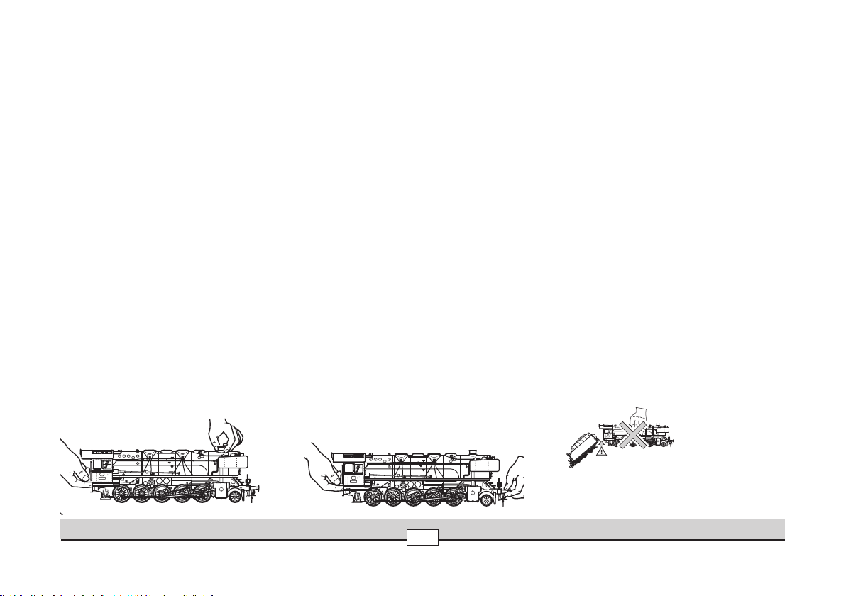
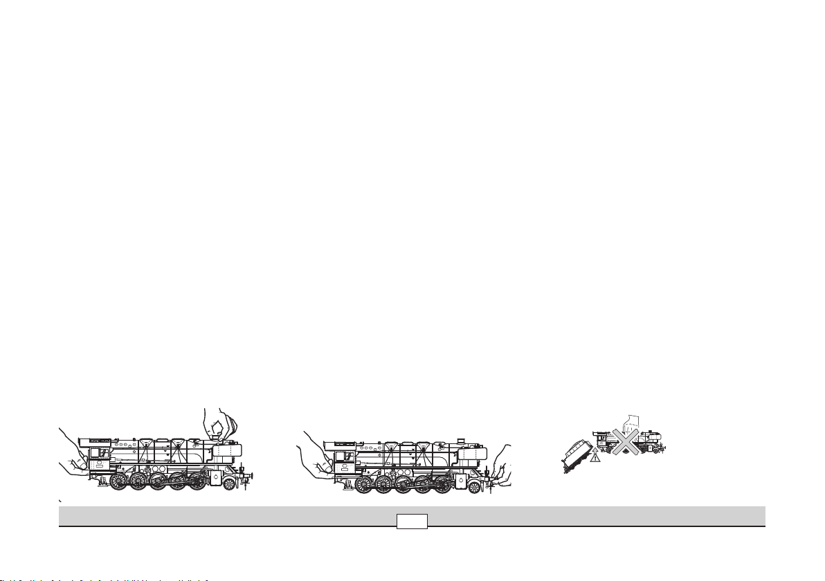
Modell aufbauen
Lok und Tender sind aus Transportschutzgründen auf einer Unterlage aufgeschraubt.
Zum Lösen des Modells von der Unterlage benötigen Sie mindestens einen Helfer.
Lösen Sie zuerst nur die Befestigungsschrauben vom Tender. Tender nicht am ab
nehmbaren Aufbau anheben! Der Tender wird am besten am Tenderkasten gehalten.
Gleisen Sie den Tender auf. Lösen Sie anschließend die Befestigungsschrauben der
Lokomotive. Geeignete Punkte zum Anheben der Lok sind die vorderen Puffer bzw. die
vordere Pufferbohle, der Schornstein und der Führerstandsboden.
Die Lok nie am Kessel anheben! Es besteht sonst Beschädigungsgefahr.
Versuchen Sie nie alleine die Lok und den Tender gleichzeitig zu tragen. Nach dem
Aufgleisen von Lok und Tender muss zuerst der Mehrfach-Stecker vom Tender an
die Buchse unter dem Führerstand angeschlossen werden. Drücken Sie anschließend die Kupplung zwischen Lok und Tender etwas nach unten, so, dass diese in
die Öffnung unterhalb der Tender-Plattform eingesteckt werden kann. Schieben Sie
Tender und Lok zusammen.
Die Kupplung rastet üblicherweise in der vorderen Stellung ein. Diese Stellung
ermöglicht den Betrieb auf 1020 mm. Wird die Kupplung in die hintere Rastung gebracht, so ergibt sich ein vorbildähnlicher Abstand zwischen Lokomotive und Tender.
In dieser Stellung können jedoch nur große Radien von mindestens
3000 mm befahren werden.
-
Setting up the Model
The locomotive and tender are screwed to a base to protect them during transport.
You will need a helper to unscrew the model from the base.
First, loosen only the mounting screws from the tender. Do not lift the tender by its
removable superstructure! It is best to hold the tender by the sides of the main part
of its body. Now, set the tender on the track. Next, loosen the mounting screws for
the locomotive. Suitable points at which you may lift the locomotive are the front
buffers or the front buffer beam, the smoke stack, and the floor of the engineer’s cab.
Never lift the locomotive by its boiler! Doing so will cause damage.
Never try to carry the locomotive and the tender together by yourself. After you
have set the locomotive and the tender on the track, the multi-pin plug from the
tender must be inserted into the socket under the engineer’s cab. Now press the
coupling between the locomotive and the tender down some what so that it can
be plugged into the opening beneath the tenderplatform. Push the tender and
locomotive together.
The coupling normally clips into the front position. This position makes it possible
to run the locomotive on curves of 1,020 mm / 40-3/16”. If the coupling is clipped
into the rear position, you will have a prototypical spacing between the locomotive
and the tender. With this setting, you can only run the locomotive on curves with a
minimum radius of at least 3,000 mm / 118-1/8”.
Betrieb • Operation • Fonctionnement • Exploitatie
4
Page 5
Montage du modèle réduit
Locomotive et tender sont solidement fixés par vis sur un support afin d’être protégés
pendant le transport. Pour libérer le modèle réduit, un aide au moins est nécessaire.
Desserrez d’abord les vis de fixation du tender. Ne soulevez pas le tender en le saisis
sant par la partie amovible, mais plutôt par la caisse! Enraillez ensuite le tender sur la
voie. Desserrez ensuite les vis de fixation de la locomotive. Les points appropriés pour
soulever la locomotive sont les tampons avant ou la traverse porte-tampons avant, la
cheminée et le dessous du poste de conduite.
Ne soulevez jamais la locomotive en la chaudière! Cela pourrait engendrer des dégâts.
Ne tentez jamais de porter tout seul la locomotive et le tender conjointement. Une
fois la locomotive et le tender posés sur la voie, la fiche multiple du tender doit être
insérée dans la douille située sous le poste de conduite. Pressez ensuite l’attelage
entre locomotive et tender vers le dessous de façon à ce que celui-ci s’emboîte dans
l’ouverture située en dessous de la plate-forme du tender. Rapprochez les deux éléments
de l’attelage et réalisez l’accouplement.
L’attelage s’encliquette usuellement dans la position avant. Celle-ci permet une
utilisation sur une voie courbe d’un rayon minimal de 1020 mm. Si l’attelage est
encliqueté dans la position arrière, l’intervalle entre locomotive et tender est réduit
de façon réaliste, mais ne permet alors une circulation que sur une voie d’un rayon
minimal de 3000 mm.
-
Het model opbouwen
Loc en tender zijn in verband met de beveiliging voor het transport op een bodemplaat
geschroefd. Voor het losmaken van het model van de bodemplaat heeft u minstens
één helper nodig.
Maak eerst de bevestigingsschroeven van de tender los. De tender niet aan de
afneembare opbouw oppakken! De tender kan het beste aan het tenderhuis opgepakt
worden. Plaats aansluitend de tender op de rails. Maak aansluitend de bevestigingsschroeven van de locomotief los. Geschikte plaatsen om de loc op te pakken zijn de
voorste buffers, dan wel de voorste bufferbalk, de schoorsteen en de bodemplaat van
het machinistenhuis.
De loc nooit aan de ketel oppakken! Er bestaat anders kans op beschadigingen.
Probeer nooit de loc en de tender tezamen te dragen.
Na het op de rails plaatsen van de loc en tender moet als eerste de meervoudige
stekker van de tender in de stekkerbus onder het machinistenhuis aangesloten wor
den. Druk aansluitend de koppeling tussen loc en tender iets naar beneden, zodat
deze in de opening onder het tenderplatform kan worden gestoken. Schuif tender
en loc aan elkaar.
De koppeling klikt normaal in de voorste stand vast. Deze stand maakt het bedrijf met
een radius van 1020 mm mogelijk. Wordt de koppeling in de achterste stand vastgeklikt,
dan ontstaat een voorbeeldgetrouwe afstand tussen loc en tender. In deze stand kunnen
alleen radiussen van minimaal 3000 mm bereden worden.
-
Betrieb • Operation • Fonctionnement • Exploitatie
5
Page 6

Funktion
Diese Lokomotive mit eingebauter mfx-Mehrzug-Elektronik bietet:
• Wahlweise Betrieb mit Gleichstrom (max ± 18 V=), Wechselstrom (Märklin
Transformer 32 VA), Märklin Delta (nur Delta Station 6607), Märklin Digital (nur
Control Unit) oder Märklin Systems. Ein Betrieb mit anderen Betriebssystemen
(Impulsbreitensteuerung, Central Control 1 etc.) ist nicht möglich.
• Die Betriebsart wird automatisch erkannt.
• Mfx-Technologie für Mobile Station / Central Station.
• 80 Mehrzugadressen (Control Unit) einstellbar. Eingestellte Adresse ab Werk: 44
• Veränderbare Anfahrverzögerung (ABV).
• Veränderbare Bremsverzögerung (ABV).
• Veränderbare Höchstgeschwindigkeit.
• Einstellen der Lokparameter elektronisch über Control Unit, Mobile Station
oder Central Station.
• Eingebaute Geräuschelektronik, nur im Betrieb mit Control Unit oder Märklin
Systems nutzbar.
Zusätzliche schaltbare Geräusche.
• Veränderbare Lautstärke der Geräusche.
• Das Modell ist für den Betrieb auf Märklin 1 – Gleisen entwickelt. Ein Betrieb auf
anderen Gleissystemen geschieht auf eigenes Risiko.
• Befahrbarer Mindestradius: 1020 mm
• Märklin Klauenkupplungen hinten. Bei Verwendung von Kupplungssystemen
anderer Hersteller sind Betriebsprobleme nicht ausgeschlossen.
Die bei normalem Betrieb anfallenden Wartungsarbeiten sind nachfolgend
beschrieben. Für Reparaturen oder Ersatzteile wenden Sie sich bitte an Ihren MärklinFachhändler.
Hinweis:
Änderungen der Lokparameter im Decoder dürfen nur wie beschrieben ausgeführt
werden (Seite 14). Für darüber hinaus gehende Änderungen, die zu Fehlverhalten
oder Beschädigungen des Decoders führen, haftet Märklin nicht; eventuelle nötige
Reparaturen werden kostenpflichtig ausgeführt.
Jegliche Garantie-, Gewährleistungs- und Schadensersatzansprüche sind ausgeschlossen, wenn
in Märklin-Produkten nicht von Märklin freigegebene Fremdteile eingebaut werden und / oder
Märklin-Produkte umgebaut werden und die eingebauten Fremdteile bzw. der Umbau für sodann
aufgetretene Mängel und/ oder Schäden ursächlich war. Die Darlegungs- und Beweislast dafür,
dass der Einbau von Fremdteilen oder der Umbau in bzw. von Märklin-Produkten für aufgetretene
Mängel und / oder Schäden nicht ursächlich war, trägt die für den Ein- und / oder Umbau verant
wortliche Person und / oder Firma bzw. der Kunde.
Mit diesem besonders präparierten Modell besitzen Sie eine exklusive Ausführung,
die den Originalzustand nach vielen Betriebsjahren bei Wind und Wetter wiedergibt.
Die künstliche Alterung wurde in sorgfältiger Handarbeit von erfahrenen Fachleuten
einzeln ausgeführt. Trotz einer abschließenden Fixierung mit Firnis bildet die zusätzliche Farbgebung jedoch keine homogene, harte Lackschicht.
Bitte behandeln Sie das Modell daher besonders vorsichtig und vermeiden Sie
Kratzen, Reiben oder Wischen an der Oberfläche und an den Details. Bitte verwenden
Sie keine Reinigungsflüssigkeiten oder Pflegebäder.
Bitte berücksichtigen Sie, dass die Ersatzteile zu diesem werkseitig gealterten Modell
nur im nicht gealterten Zustand verfügbar sind.
-
Betrieb • Operation • Fonctionnement • Exploitatie
6
Page 7
Function
This locomotive has a built-in mfx-multi-train electronic circuit and offers these
features:
• Optional operation with DC power (max. ± 18 volts DC),
AC power (with Märklin 32 VA transformer), with Märklin Delta (only with the
6607 Delta Station), Märklin Digital (only with the Control Unit), or Märklin Systems. This locomotive is not designed for operation with locomotive controllers
for other systems (example: pulse width control, operation with the Central
Control 1 or similarsystems).
• The mode of operation is automatically recognized.
• 80 multi-train addresses (Control Unit) can be set. Address that set at the factory: 44.
• Mfx technology for the Mobile Station / Central Station.
• Adjustable acceleration (ABV).
• Adjustable Braking delay (ABV)
• Adjustable maximum speed.
• Setting the locomotive parameters electronically with the Control Unit, Mobile
Station or Central Station.
• Built-in sound effects circuit, can only be used in operation with the Control Unit
or Märklin Systems.
Additional sound effects that can be controlled.
• Volume can be changed for the sound effects.
• The model is designed for operation on Märklin 1 Gauge track. As the consumer
you assume the risk for operating on other makes of track.
• Minimum radius for operation: 1020 mm / 40-5/32“.
• Märklin claw coupler on the rear. You may have operations problems if you use
other makes of couplers.
Maintenance procedures that become necessary with normal operation of the
locomotive are described below. Please see your authorized Märklin dealer for repairs
or spare parts.
Note:
Changes to the locomotive parameters in the decoder may only be carried out as
described (page 15). Märklin is not liable for changes beyond this that cause malfunctions or damages to the decoder; the cost for any necessary repairs must be borne by
the consumer.
No warranty or damage claims shall be accepted in those cases where parts neither manufactured nor approved by Märklin have been installed in Märklin products or where Märklin products
have been converted in such a way that the non-Märklin parts or the conversion were causal to
the defects and / or damage arising. The burden of presenting evidence and the burden of proof
thereof, that the installation of non-Märklin parts or the conversion in or of Märklin products
was not causal to the defects and / or damage arising, is borne by the person and / or company
responsible for the installation and / or conversion, or by the customer.
This specially prepared model is an exclusive version, which reproduces the condition
of the original after many years of operation in wind and weather.
The artificial weathering was separately applied with careful hand work by expe
rienced artisans. Despite a final fixing of the colors with varnish, this additional
application of color does not form a homogeneous, hard coating.
Therefore, please handle the model with special care and avoid, scratching,
rubbing, or wiping the surface and the details. Please do not use liquid cleaners or
cleaning solutions.
Please note that the spare parts for this model weathered at the factory are only
available in non-weathered version.
Betrieb • Operation • Fonctionnement • Exploitatie
7
Page 8
Fonctionnement
Cette locomotive possède un équipement électronique mfx pour conduite multitrain:
• Au choix, exploitation conventionnelle avec courant continu (max ± 18 volts =),
courant alternatif (Transformer 32 VA), exploitation avec Märklin Delta (unique
ment Delta Station 6607), Märklin Digital (uniquement Control Unit) ou Märklin
Systems. Une exploitation avec d’autres systèmes d’exploitation (courant à
largeur d’impulsion variable, Central Control 1, etc.) n’est pas possible.
• Le mode d’exploitation est automatiquement détecté.
• Technologie mfx pour Mobile Station / Central Station.
• 80 adresses pour conduite multitrain (Control Unit) sont disponibles. Adresse
réglée en usine: 44.
• Temporisation d’accélération réglable (ABV).
• Temporisation de freinage réglable (ABV).
• Vitesse maximale réglable.
• Réglage des paramètres de la loco électroniquement à l’aide de la Control Unit, de
la Mobile Station ou de la Central Station.
• Bruiteur électronique intégré, utilisable uniquement lors d’exploitation avec la
Control Unit ou Märklin Systems.
Bruitages complémentaires commutables.
• Volume des bruitages réglable.
• Le modèle réduit est conçu pour rouler sur des voies Märklin 1. Le faire rouler sur
des voies d’autres systèmes comporte des risques.
• Rayon minimal d’inscription en courbe: 1020 mm.
• Attelage à mâchoires Mäklin à l’arrière. En cas d’utilisation d’un système pro
venant d’un autre fabricant, des problèmes sont susceptibles de survenir.
Les travaux d‘entretien occasionnels à effectuer en exploitation normale sont décrits
plus loin. Pour toute réparation ou remplacement de pièces, adressez-vous à votre
détaillant-spécialiste Märklin.
-
-
Remarque :
Pour modifier les paramètres de la locomotive dans le décodeur, procédez impé
rativement de la manière décrite (page 16). La garantie Märklin ne couvre pas les
modifications ne respectant pas scrupuleusement les instructions et pouvant être à
l’origine d’un dysfonctionnement ou d’une détérioration du décodeur ; d’éventuelles
réparations seront facturées.
Tout recours à une garantie commerciale ou contractuelle ou à une demande de dommages-intérêt est exclu si des pièces non autorisées par Märklin sont intégrées dans les produits Märklin et
/ ou si les produits Märklin sont transformés et que les pièces d’autres fabricants montées ou la
transformation constituent la cause des défauts et / ou dommages apparus. C’est à la personne
et / ou la société responsable du montage / de la transformation ou au client qu’incombe la
charge de prouver que le montage des pièces d’autres fabricants sur des produits Märklin ou la
transformation des produits Märklin n’est pas à l’origine des défauts et ou dommages apparus.
Avec ce modèle particulièrement élaboré, vous possédez une version unique qui
reste conforme à l‘état d‘origine après de nombreuses années d‘utilisation par
tous les temps.
Le vieillissement artificiel a été réalisé à la main et avec précaution sur chaque
modèle par des spécialistes. Malgré une fixation finale au vernis, la coloration supplémentaire ne forme cependant pas une couche de vernis homogène et dure.
Par conséquent, traitez ce modèle avec beaucoup de soin et évitez de rayer, de frotter
ou d‘essuyer les surfaces et les détails. N‘utilisez aucun produit de nettoyage ou
produit traitant.
Notez que les pièces de rechange pour ce modèle « vieilli » en usine ne sont disponibles qu’à l’état « neuf ».
Betrieb • Operation • Fonctionnement • Exploitatie
8
Page 9

Werking
Deze loc met ingebouwde mfx-elektronica biedt u:
• Naar keuze conventioneel bedrijf (wisselstroom met de Transformer 32 VA of
gelijkstroom [max +/– 18 Volt=] ), bedrijf met Märklin Delta (alleen het Delta
Station 6607), Märklin Digital (Control Unit) of het Märklin Systems. Het bedrijf
met rijregelaars van andere systemen (bijv. impulsbreedte sturing, gebruik van de
Central-Control 1 of een dergelijk systeem) is niet mogelijk.
• Het bedrijfssysteem wordt automatisch herkend.
• Mfx-technologie voor het Mobile Station /
Central Station.
• 80 meertreinen-adressen (4 daarvan voor het Delta-systeem) instelbaar. Ingesteld
adres vanaf de fabriek: 44.
• Instelbare optrekvertraging.
• Instelbare afremvertraging.
• Instelbare maximumsnelheid.
• Elektronische instelling van de locomotiefparameters via de Control Unit,
Mobile Station of Central Station.
• Ingebouwde geluidselektronica, alleen bruikbaar in het bedrijf met de Control
Unit of Märklin Systems.
Extra schakelbare geluiden.
• Volume van de geluiden instelbaar.
• Het model is ontwikkeld voor het gebruik op het Märklin Spoor 1 railsysteem. Het
gebruik op een ander railsysteem geschied op eigen risico.
• Berijdbare minimumradius: 1020 mm.
• Märklin klauwkoppeling achter. Bij het gebruik van koppelingssystemen van
andere fabrikanten zijn storingen niet uit te sluiten.
De in het normale bedrijf voorkomende onderhoudswerkzaamheden zijn verderop beschreven. Voor reparatie of onderdelen kunt u zich tot uw Märklin winkelier wenden.
Opmerking:
Het wijzigingen van de loc-parameters in de decoder mag enkel en alleen op de
beschreven wijze worden uitgevoerd (pagina 17). Elke op andere wijze uitgevoerde
wijziging, die tot storing of beschadiging van de decoder leidt, valt buiten de garantie
van Märklin; eventuele noodzakelijke reparaties worden met berekening van de
kosten uitgevoerd.
Elke aanspraak op garantie en schadevergoeding is uitgesloten, wanneer in Märklin-producten
niet door Märklin vrijgegeven vreemde onderdelen ingebouwd en / of Märklin-producten omgebouwd worden en de ingebouwde vreemde onderdelen resp. de ombouw oorzaak van nadien
opgetreden defecten en / of schade was. De aantoonplicht en de bewijslijst daaromtrent, dat
de inbouw van vreemde onderdelen in Märklin-producten of de ombouw van Märklin-producten
niet de oorzaak van opgetreden defecten en / of schade is geweest, berust bij de voor de inbouw
en/of ombouw verantwoordelijke persoon en / of firma danwel bij de klant.
Met dit geprepareerde model bezit u een exclusieve uitvoering die de werkelijke
toestand weergeeft na vele bedrijfsjaren in weer en wind.
De kunstmatige veroudering werd zorgvuldig met de hand aangebracht door
ervaren vakmensen. Ondanks de vernislaag die is aangebracht over deze patinering
geeft dit toch geen homogene harde laklaag.
Behandel het model daarom a.u.b voorzichtig en vermijd krassen, schuur en veegplek
ken op de oppervlakte en de details. Gebruik a.u.b. geen vloeibare reinigingsmiddelen
of reinigingsbaden.
Wees er op bedacht dat de onderdelen voor dit model, dat vanaf de fabriek “verou
derd” is, alleen in de niet verouderde” toestand beschikbaar zijn.
-
Betrieb • Operation • Fonctionnement • Exploitatie
9
Page 10
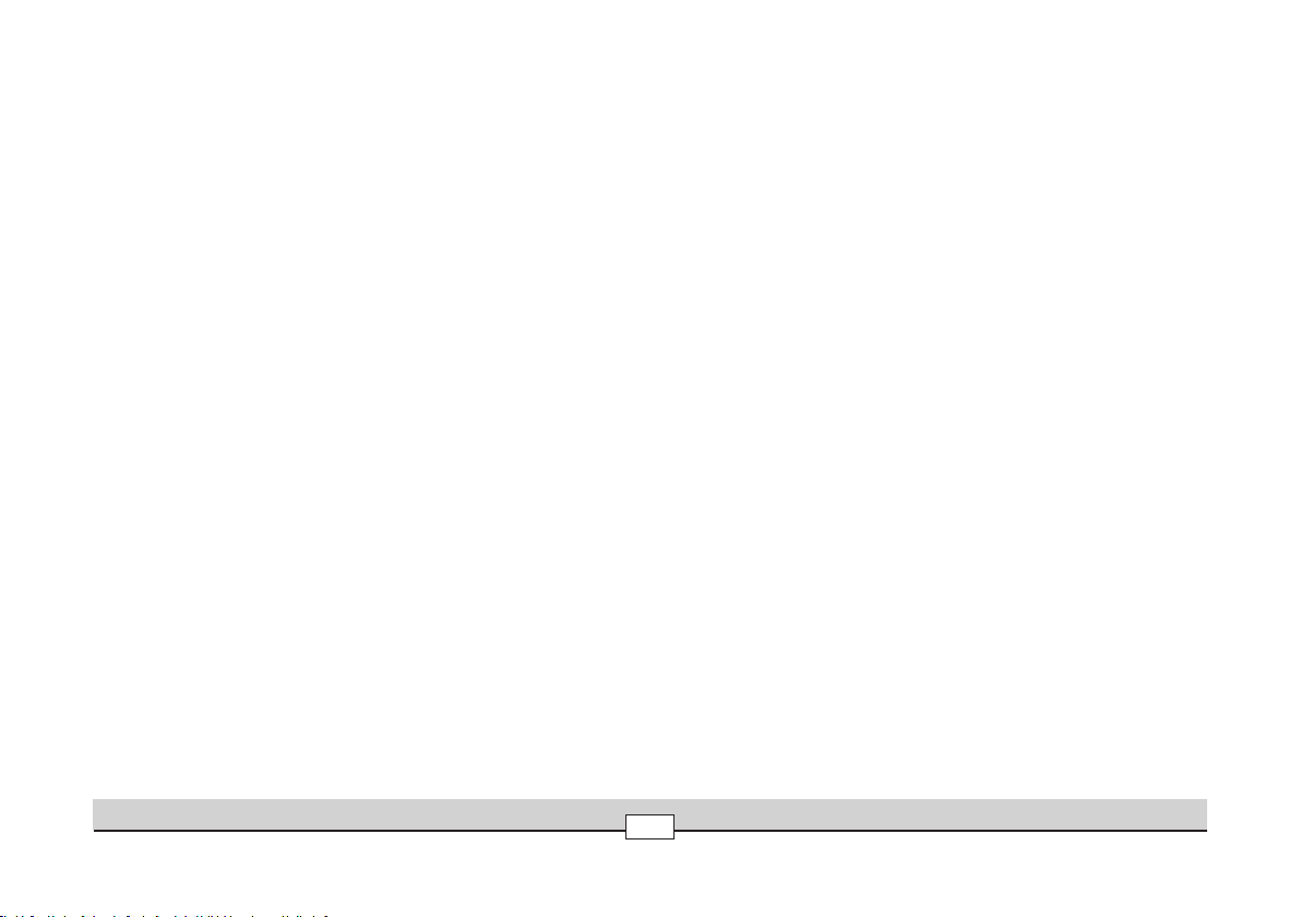
Schaltbare Funktionen
STOP
mobile station
systems
STOP
mobile station
systems
1
5
central
station
60212
Controllable Functions
Fonctions commutables
Schakelbare functies
H
Betriebsgeräusch
Operating sounds
Bruit d’exploitation
bedrijfsgeluiden
Geräusch: Lokpfeife
Sound effects: Locomotive whistle
Bruitage : Sifflet locomotive
Geluid: locfluit
AC/DC
~/=
1)
Dauernd
1)
Always
1)
Activé
1)
Aan
1)
Dauernd
1)
Always
1)
Activé
1)
Aan
— f2
— f3
— f4
— —
function + off
f1
Taste 7 bei Symbol
Button 7 by symbol
Touche 7 à côté symbole
Toets 7 bij het symbool
Taste 3 bei Symbol
Button 3 by symbol
Touche 3 à côté symbole
Toets 3 bij het symbool
Taste 4 bei Symbol
Button 4 by symbol
Touche 4 à côté symbole
Toets 4 bij het symbool
Taste 6 bei Symbol
Button 6 by symbol
Touche 6 à côté symbole
Toets 6 bij het symbool
Taste 8 bei Symbol
Button 8 by symbol
Touche 8 à côté symbole
Toets 8 bij het symbool
f0
f1
f2
f3
f4
f5
1) => Intensität abhängig von der Höhe der Versorgungsspannung. / Intensity dependent on the level of supply voltage. /
L’intensité est fonction de la tension d’alimentation. / Intensiteit afhankelijk van de hoogte van de voedingsspanning.
Betrieb • Operation • Fonctionnement • Exploitatie
10
Page 11
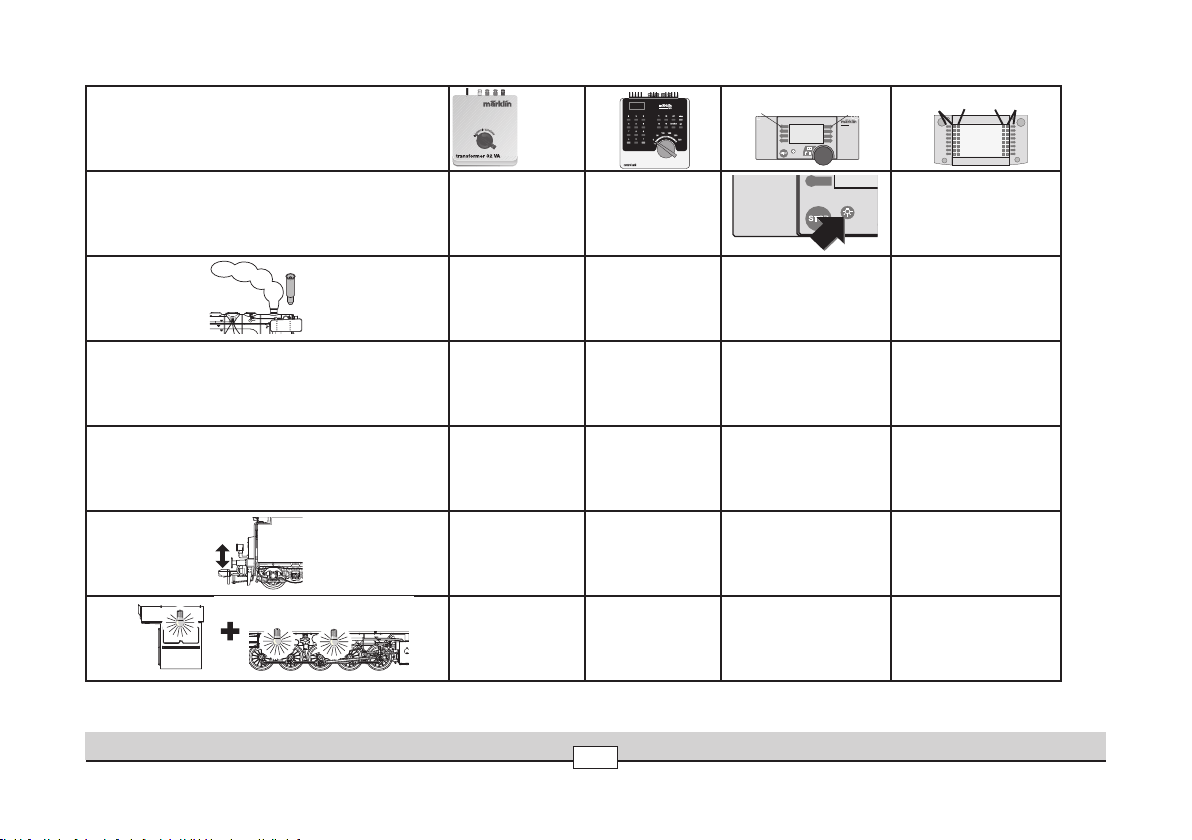
Schaltbare Funktionen
STOP
mobile station
systems
1
5
central
station
60212
Controllable Functions
Fonctions commutables
Schakelbare functies
Geräusch: Luftpumpe
Sound Effects: Air Pump
Bruitage compresseur
Geluid: luchtpomp
Geräusch: Rangierpfeife
Sound effects: switching range whistle
Bruitage: sifflet de manoeuvre
Geluid van rangeerhoorn
Rangiergang (nur ABV)
Low Speed Switching Range (only with ABV)
Mode manoeuvre (seulement ABV)
Rangeerstand (alleen ABV)
Geräusch: Bremsenquietschen aus
Sound Effect: To turn the Squealing Brakes off
Déconnecter bruitage de crissement des freins
Geluid: piepende remmen uitschakelen
Geräusch: Dampf ablassen
Sound effect: Blowing off steam
Bruitage : Échappement de la vapeur
Geluid: stoom afblazen
Geräusch: Kohle schaufeln
Sound effect: Coal being shoveled
Bruitage : Pelletage du charbon
Geluid: kolenscheppen
AC/DC
~/=
Taste 1 bei Symbol
— —
— —
— —
— — — f9
— — — f10
— — — f11
Button 1 by symbol
Touche 1 à côté symbole
Toets 1 bij het symbool
Taste 5 bei Symbol
Button 5 by symbol
Touche 5 à côté symbole
Toets 5 bij het symbool
Taste 2 bei Symbol
Button 2 by symbol
Touche 2 à côté symbole
Toets 2 bij het symbool
f6
f7
f8
Betrieb • Operation • Fonctionnement • Exploitatie
11
Page 12

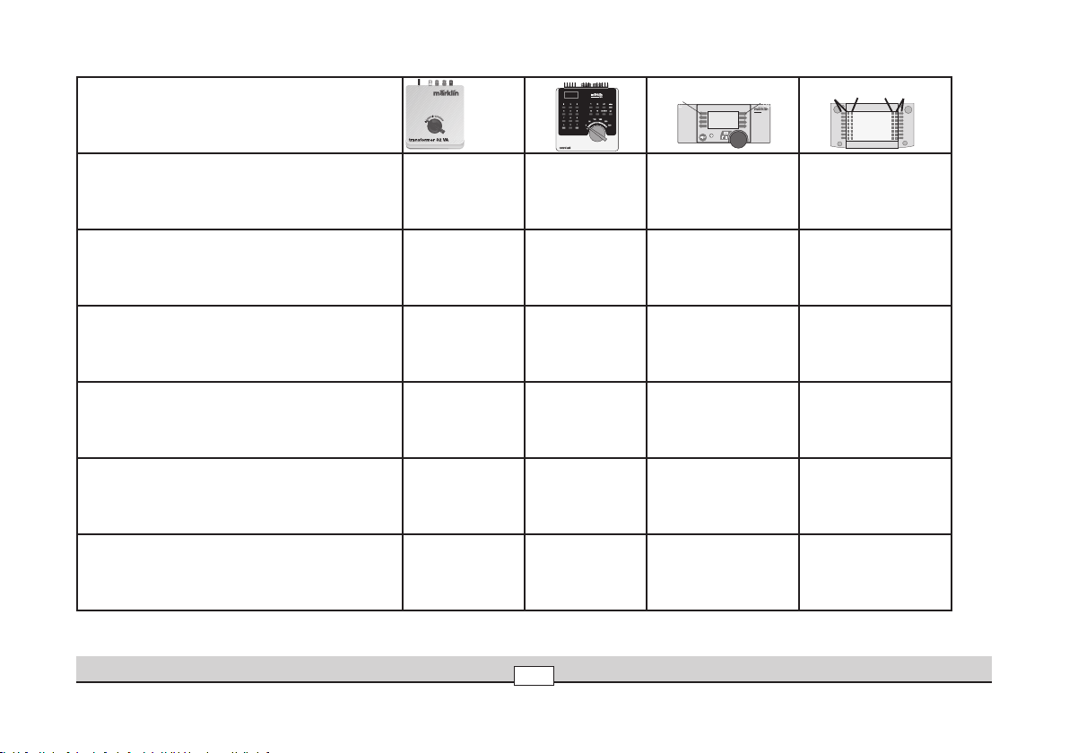
Schaltbare Funktionen
STOP
mobile station
systems
1
5
central
station
60212
Controllable Functions
Fonctions commutables
Schakelbare functies
Geräusch: Schüttelrost
Sound effect: Rocker grate
Bruitage : Grille à secousses
Geluid: schudrooster
Geräusch: Lichtmaschine
Sound effect: Generator
Bruitage : Dynamo d‘éclairage
Geluid: generator
Geräusch: Injektor
Sound effect: Injector
Bruitage : Injecteur
Geluid: injecteur
Geräusch: Wasserpumpe
Sound effect: Water pump
Bruitage : Pompe à eau
Geluid: waterpomp
AC/DC
~/=
—
— — — f13
— — — f14
— — — f15
—
— f12
Betrieb • Operation • Fonctionnement • Exploitatie
12
Page 13

Vorsicht:
Um Beschädigungen an der Elektronik zu vermeiden, ist es notwendig, dass die TelexKupplung spätestens eine Minute nach Betätigung wieder abgeschaltet wird. Bei
der Bedienung durch die Mobile Station oder Central Station kann dieses manuelle
Ausschalten entfallen.
Attention :
Pour éviter d’endommager l’électronique, il est nécessaire de déconnecter l’attelage
Telex au plus tard une minute après l’avoir actionné. Si la commande se fait via la
Mobile Station ou la Central Station, cette déconnexion manuelle est inutile.
Caution:
In order to avoid damage to the electronic circuit, you must turn the Telex coupler
off no later than one minute after you have activated it. If you are using the Mobile
Station or the Central Station to operate the locomotive, you do not have to worry
about manually turning this function off.
Betrieb • Operation • Fonctionnement • Exploitatie
Voorzichtig:
Om beschadigingen aan de elektronica te vermijden is het noodzakelijk om de
telex-koppeling binnen één minuut na het inschakelen weer uit te schakelen. Bij het
besturen via het Mobile Station of het Central Station kan dit handmatige uitschakelen vervallen.
13
Page 14

Lokparameter mit der Control Unit einstellen
1
1
99
1
2
80
1
80
1
2
1
01
01
1
1
2
10
10
1
1. Voraussetzung: Aufbau wie Grafik 1. Nur die zu verändernde Lok ist auf dem Gleis.
2. „Stop“- und „Go“-Taste gleichzeitig drücken, bis „99“ in der Anzeige aufblinkt.
3. „Stop“-Taste drücken.
4. Lokadresse „80“ eingeben.
5. Umschaltbefehl am Fahrregler dauernd schalten. Dabei die „Go“-Taste drücken.
=> Licht an der Lok blinkt. Wenn nicht ab Schritt 2 wiederholen.
6. Registernummer für den zu ändernden Parameter eingeben.
7. Fahrtrichtungswechsel betätigen.
8. Neuen Wert eingeben
9. Fahrtrichtungswechsel betätigen.
10. Vorgang beenden mit Drücken der „Stop“-Taste.
Anschließend Drücken der „Go“-Taste.
Grafik 1
Parameter Register Wert
Adresse 01 01 - 80
Anfahrverzögerung 03 01 - 63
Bremsverzögerung 04 01 - 63
Höchstgeschwindigkeit 05 01 - 63
Rückstellen auf Serienwerte 08 08
Lautstärke 63 01 - 63
Betrieb • Operation • Fonctionnement • Exploitatie
14
Page 15

Betrieb mit Mobile Station / Central Station
• Lok aufgleisen. Die Lok meldet sich selbsttätig in der Lokliste an.
• Beim Betrieb:
Geschwindigkeitsanzeige blinkt => keine Verbindung zur Lok.
• Lok abmelden:
1. Lok vom Gleis entfernen.
2. Lokeintrag löschen.
• Eine Adressänderung ist nicht notwendig.
• Lokparameter mit der Mobile Station verändern: Beachten Sie die Hinweise in der
Anleitung zur Mobile Station / Central Station.
Lokparameter mit der Mobile Station verändern
1. Lok aus der Lokliste auswählen.
2. Zum Untermenü „LOKÄNDERN“ wechseln.
3. Zum Untermenü „ADRESSE“, „VMAX“, „VOL“, „ACC“ oder „DEC“ wechseln.
4. Neuen Wert eingeben und übernehmen.
Beachten Sie die Hinweise in der Anleitung zur Mobile Station.
Lokparameter mit der Central Station verändern.
Beachten Sie die Hinweise in der Gebrauchsanleitung zur Central Station. Die Lok
54323 ist in der Datenbank von der Central Station zu finden.
Hinweis:
Beim Umprogrammieren der Lokparameter dürfen keine andere Lokomotivmodelle
oder sonstige Verbraucher von der Central Station versorgt werden.
Betrieb • Operation • Fonctionnement • Exploitatie
15
Page 16

Setting Locomotive Parameters with the Control Unit
1
1
99
1
2
80
1
80
1
2
1
01
01
1
1
2
10
10
1
1. Requirement: Setup as in diagram 1. Only the locomotive to be changed can be on
the track.
2. Press the “Stop” and “Go” at the same time until “99” blinks in the display.
3. Press the “Stop” button.
4. Enter the address „80“.
5. Hold the speed control knob in the reverse direction position constantly. Press the
“Go” button while you do this. The headlight on the locomotive will blink. If no,
repeat starting at Step 2.
6. Enter the register number for the parameter to be changed .
7. Activate the direction reversal.
8. Enter new value.
9. Activate the direction reversal.
10. End the procedure by pressing the “Stop”
button. Now press the “Go” button.
Diagramm 1
Parameter Register Value
Address 01 01 - 80
Acceleration delay 03 01 - 63
Braking delay 04 01 - 63
Maximum speed
05 01 - 63
Reset to series values 08 08
Volume
Betrieb • Operation • Fonctionnement • Exploitatie
16
63 01 - 63
Page 17

Operation with the Mobile Station/Central Station
• Set the locomotive on the track. The locomotive automatically registers itself in
the locomotive list.
• During operation:
Speed indicator blinks => no connection to the locomotive.
• Taking the locomotive out of the locomotive list:
1. Remove the locomotive from the track.
2. Delete the locomotive entry.
• It is not necessary to change the address.
• Changing Locomotive Parameters with the Mobile Station: Please note the
information in the instructions for the Mobile Station / Central Station.
Changing Locomotive Parameters with the
Mobile Station
1. Select the locomotive from the locomotive list.
2. Change to the submenu “EDIT LOC”.
3. Change to the submenu “ADDRESS”, “VMAX”, “VOL“, “ACC” or “DEC”.
4. Enter the new value and accept it into the system.
Note the references and information in the instructions for the Mobile Station.
Changing Locomotive Parameters with the
Central Station.
Note the references and information in the instructions for the Central Station. The
54323 locomotive can be found in the database for the Central Station.
Note:
When you are reprogramming the locomotive parameters, no other locomotive or
other units can be receiving power from the Central Station.
Betrieb • Operation • Fonctionnement • Exploitatie
17
Page 18

Réglage des paramètres de la loco avec la Control Unit
1
1
99
1
2
80
1
80
1
2
1
01
01
1
1
2
10
10
1
1. Condition: Montage comme sur illustration 1. Seule la loco à modifier peut se
trouver sur la voie.
2. Pressez simultanément les touches „Stop“ et „Go“ jusqu’à ce que le nombre „99“
clignote sur l’écran.
3. Pressez la touche „Stop“.
4. Introduisez l’adresse „80“.
5. Tout en procédant à l’inversion sur le régulateur, pressez la touche „Go“. Les feux
clignotent sur la loco. Si ce n’est pas le cas, répétez l’étape 2.
6. Introduisez le numéro de registre pour le paramètre à modifier.
7. Exécutez l’inversion du sens de marche.
8. Introduisez la nouvelle valeur.
9. Exécutez l’inversion du sens de marche.
10. Terminez le processus en pressant la touche „Stop“. Ensuite, pressez la touche „Go“.
Illustration 1
Paramètre Registre Valeur
Addresse 01 01 - 80
Temporisation de démarrage
Temporisation de freinage
Vitesse maximale
03 01 - 63
04 01 - 63
05 01 - 63
Remettre aux valeurs de série 08 08
Volume haut-parleur
Betrieb • Operation • Fonctionnement • Exploitatie
18
63 01 - 63
Page 19

Exploitation avec Mobile Station / Central Station
• Enrailler la locomotive. La locomotive signale automatiquement sa présence dans
la liste des locos.
• Lors de l’exploitation:
L’indicateur de vitesse clignote => aucune liaison avec la loco.
• Appeler loco:
1. Enlever loco de la voie.
2. Effacer entrée loco.
• Une modification de l’adresse n’est pas nécessaire.
• Modification des paramètres de la loco avec la Mobile Station:Respectez les re
marques mentionnées dans l’instruction accompagnant la Mobile Station /Central
Station.
-
Modification des paramètres de la locomotive à l‘aide de
la Mobile Station
1. Sélectionnez la loco dans la liste.
2. Allez au sous-menu „MODIF LOC“.
3. Allez au sous-menu „ADRESSE“, „VMAX“, „VOL“, „ACC“ ou „DEC“.
4. Entrez la nouvelle valeur et acceptez.
Tenir compte des remarques faites dans les instructions de la Mobile Station.
Modification des paramètres de la locomotive à l‘aide de
la Central Station.
Tenir compte des remarques faites dans les instructions de la Central Station. La
locomotive 54323 se trouve dans la banque de données de la Central Station.
Remarque :
Lors du changement de programmation des paramètres de la locomotive, aucune
autre locomotive ou aucun autre consommateur ne doit être alimenté par la
Central Station.
Betrieb • Operation • Fonctionnement • Exploitatie
19
Page 20

Locparameters instellen met de Control Unit
1
1
99
1
2
80
1
80
1
2
1
01
01
1
1
2
10
10
1
1. Voorwaarde: opbouw zoals tekening 1. Alleen de loc die gewijzigd moet worden
op de rails.
2. ”Stop”- en ”Go”-toets gelijktijdig indrukken tot ”99” in het display oplicht.
3. ”Stop”-toets indrukken.
4. Adres „80“ invoeren.
5. Omschakelcommando met de rijregelaar continu bedienen. Daarbij de ”Go”-toets
indrukken. De verlichting van de loc knippert. Als dit niet het geval is, vanaf stap
2 herhalen.
6. Het registernummer van de te wijzigen parameter invoeren.
7. Rijrichtingomschakeling bedienen.
8. Nieuwe waarde invoeren.
9. Rijrichtingomschakeling bedienen.
10. Programmering beëindigen door het indrukken van de ”Stop”-toets. Aansluitend
de ”Go”-toets indrukken.
Tekening 1
Parameter Register
Waarde
Adres 01 01 - 80
Optrekvertraging
03 01 - 63
Afremvertraging 04 01 - 63
Maximumsnelheid 05 01 - 63
Terugzetten naar serie-instellingen
Volume
Betrieb • Operation • Fonctionnement • Exploitatie
20
08 08
63 01 - 63
Page 21

Bedrijf met Mobile Station / Central Station
• Loc op de rails plaatsen. De loc meldt zichzelf aan in de loclijst.
• Bij het bedrijf:
snelheidsweergave (balk) knippert => geen verbinding met de loc.
• Loc afmelden:
1. loc van de rails nemen
2. loc invoer wissen.
• Het wijzigen van het adres is niet nodig.
• Locparameter wijzigen met het Mobile Station: Lees ook de
opmerkingen in de gebruiksaanwijzing van het Mobile Station / Central Station.
Locparameter met het Mobile Station wijzigen
1. Loc uit de loclijst kiezen.
2. Ga naar het nevenmenu ”WYZIG LOC”.
3. Ga naar het nevenmenu ”ADRES”, ”MAX.SNELH.”, „VOL“, ”OPTREKKEN” of
”AFREMMEN”.
4. Nieuwe waarde invoeren en overnemen.
Neem ook de aanwijzingen in de gebruiksaanwijzing van het Mobile Station in acht.
Locparameter met het Central Station wijzigen.
Neem de aanwijzingen in de gebruiksaanwijzing van het Central Station in acht. De
loc 54323 is aanwezig in de databank van het Central Station.
Opmerking: bij het omprogrammeren van de locparameter mogen geen andere locomotieven of andere verbruikers door het Central Station van stroom worden voorzien.
Betrieb auf der Anlage • Operation on a layout • Exploitation sur réseau • Bedrijf op een modelbaan
21
Page 22

Anschluss der Gleisanlage
Um Spannungsverluste auf der Anlage zu vermeiden ist immer auf gutes Zusammenpassen der Schienenverbindungslaschen zu achten. Alle 2 bis 3 m ist eine
neue Stromeinspeisung über die Anschlussklemmen 5654 empfehlenswert. Die
Verwendung der Gleisklammern 56031 bei zeitweise aufgebauten Anlagen verringert
ebenfalls die Spannungsverluste.
Befahren von Steigungen
Im Gegensatz zum Vorbild können mit einer Modellbahn auch größere Steigungen
befahren werden. Im Normalfall sollte eine Steigung bei maximal 3 Prozent liegen.
Im Extremfall sind bei entsprechend eingeschränkter Zugleistung maximal 5 Prozent
möglich. Der Anfang und das Ende der Steigung sind auf jeden Fall auszurunden. Der
Unterschied in der Steigung zwischen zwei mindestens 300 mm langen Gleisstücken
darf maximal 1 bis 1,5 Prozent betragen.
Befahren von gebogenen Gleisen und Weichen
Bei ungünstiger Konstellation können die Schienenräumer der Lokomotive eventuell am
Stellrad des Weichenantriebs streifen. Montieren Sie in diesem Fall den Weichenantrieb auf
die andere Weichenseite.
Vorsicht:
Beim ersten Einsatz der Lok auf Ihrer Anlage sollten Sie langsam und vorsichtig Ihre
komplette Anlage abfahren. Achten Sie dabei darauf, dass die Lokomotive keine
Gegenstände auf der Modellbahn berührt oder sogar daran hängen bleibt.
Diese Lok fährt nur auf Gleisbögen mit einem Radius größer / gleich 1020 mm. Die vorne
montierte Schraubenkupplung ist nur für das Ankuppeln von Wagen in einer Vitrine
geeignet. Je größer der befahrene Mindestradius gewählt wird, umso vorbildgerechter
ist das Erscheinungsbild der Lokomotive auf der Anlage. Neben diesem optischen Vorteil
bei möglichst großen Mindestradien ergibt sich natürlich auch ein geringerer Verschleiß
an der Lokomotive und an den Gleisen. Die stärkste Beanspruchung für das Material stellt
daher eine kreisförmige Anlage bestehend nur aus gebogenen Gleisen mit
1020 mm – Radius dar.
Die Grundvoraussetzung für einen verschleißarmen und kontaktsicheren Betrieb ist
nur bei regelmäßigem Reinigen der Gleisanlage gesichert. Verwenden Sie hierzu
keine scharfen Reinigungsmittel. Durch Einsatz eines Kontaktsprays aus dem Elektonikbereich kann die Betriebssicherheit erhöht werden.
Betrieb auf der Anlage • Operation on a layout • Exploitation sur réseau • Bedrijf op een modelbaan
Connections between the track layout and the
transformer
Rail joiners must fit well on the rails of the track to which they are joined to avoid
voltage drop on the layout. We recommend that you install feeder wires every 2 to
3 meters (10 to 16 feet) using the 5654 feeder clips. Using the 56031 track clips on
temporary layouts will minimize the voltage loss.
Operating the locomotive on grades
In contrast to the prototype a locomotive on a model railroad can operate up steeper
grades. As a general rule a grade should be no steeper than 3%. In extreme situations a
maximum grade of 5% is permissible, keeping in mind that the locomotive‘s tractive effort
will be less. The beginning and the end of the grade must always work gradually up to the
maximum grade for the route. The maximum allowable difference in grade between two
track sections, each with a minimum length of 300 mm (11-3/4”) is 1 to 1.5 percent.
Negotiating Curved Track and Turnouts
When the track is set up in certain ways, the rail clearance bars on the locomotive’s
front can hit the adjustment wheel on the turnout mechanism. In this situation, mount
the turnout mechanism on the other side of the turnout.
Caution:
You should run the locomotive slowly and carefully over your entire layout the first
time you use the locomotive. Be careful that the locomotive does not hit any objects
on the layout or that it becomes caught on anything.
This locomotive requires curves with a radius of 1,020 mm / 40-3/16” or greater for
operation. The reproduction prototype coupler mounted on the front of the locomotive is
only suitable for coupling to cars in a display case. The larger the minimum radius used
for running the locomotive, the more prototypical the locomotive will look on a layout. In
addition to this visual advantage with minimum radii as large as possible, there is also less
wear and tear on the locomotive and the track. A layout consisting only of curved track with
a radius of 1,020 mm / 40-3/16” place the greatest demands on the material.
Only regular cleaning of the track will safeguard the basic condition for operation
with little wear and tear, and reliable electrical contact. Do not use any harsh cleansers for this purpose. The operational reliability can be increased by using a contact
spray from the electronics industry.
22
Page 23

Connexion des voies ferrées
Pour éviter des pertes de potentiel sur l‘installation, il faut veiller à ce que les éclisses de liaison des rails soient toujours parfaitement adaptées. Une nouvelle alimentation électrique est conseillée tous les 2 à 3 m au moyen des griffes d‘alimentation
5654. L‘utilisation des étriers de maintien 56031 sur des réseaux temporaires permet
de réduire également les pertes de courant.
Franchissement des côtes
Contrairement à l‘original, la maquette est également en mesure de franchir des côtes
assez importantes. En temps normal, une côte devrait être de l‘ordre de 3% maximum.
A l‘extrême limite, 5% sont envisageables avec une puissance du train réduite en conséquence. Le début et la fin de la côte doivent en tous cas être arrondis. La différence
de pente entre deux éléments de voie d‘au moins 300 mm de longueur doit être de 1 à
1,5% maximum.
Circulation sur voies et aiguillages en courbe
En cas de configuration d’aiguillages défavorable, le chasse-pierres peut éventuellement heurter le capot d’un moteur d’aiguillage. Dans ce cas, installez le moteur
d’aiguillage de l’autre côté de celui-ci.
Attention:
Lors de la première mise en route de la locomotive sur votre réseau ferroviaire, il
est conseillé de faire rouler le modèle réduit à basse vitesse et avec prudence sur
l’ensemble des voies. Veillez à ce que la locomotive ne heurte aucun objet sur le
réseau ou y reste immobilisée.
Cette locomotive ne peut emprunter que des courbes d‘un rayon minimal de 1020 mm.
L‘attelage à vis monté sur le devant de la locomotive ne peut servir que pour accoupler des
wagons en vitrine. Plus grand est le rayon d’inscription en courbe, plus réaliste est l’aspect
de la locomotive sur le réseau. Outre l’avantage optique obtenu avec des voies à grand
rayon de courbure, on bénéficie évidemment d’une moindre usure des roues et de la voie.
Un réseau en forme de cercle composé uniquement de rails courbes d’un rayon de 1020 mm
représente par conséquent la contrainte la plus forte pour le matériel.
La condition de base pour une exploitation comportant une usure minimale et un bon
contact électrique est un nettoyage régulier des voiesdu réseau. Pour ce faire, n’utilisez
pas d’agents de nettoyage agressifs. L’utilisation d’un spray de nettoyage pour composants électroniques peut améliorer la sécurité d’exploitation.
Wartung • Maintenance • Entretien • Onderhoud
Aansluiting van de sporen
Om spanningsverlies op de modelbaan te voorkomen moeten de raillassen altijd
goed op elkaar aansluiten. Om de 2 à 3 meter moet de voeding opnieuw op de rails
gezet worden. Daarbij zijn de aansluitklemmen 5654 aan te raden. Het gebruik van
de railklemmen 56031 bij tijdelijk opgebouwde modelbanen vermindert eveneens het
spanningsverlies.
Berijden van hellingen
In tegenstelling tot het grote voorbeeld kunnen met een modelbaan ook grotere
hellingen bereden worden. Normaal moet een helling maximaal 3 procent zijn. In
extreme gevallen is maximaal 5 procent mogelijk, maar dan moet rekening gehouden
worden met een evenredig verlies aan vermogen. Het begin en het einde van de
helling moeten altijd gerond worden. Het verschil in de helling tussen twee tenminste
300 mm lange railstukken mag maximaal 1 à 1,5 procent bedragen.
Rijden op gebogen rails en wissels
Bij een ongunstige constellatie kunnen de baanruimers van de locomotieven eventueel met de stelknop op de wisselaandrijving in aanraking komen. Monteer in dat
geval de wisselaandrijving aan de andere kant van het wissel.
Voorzichtig:
bij de eerste rit op uw baan dient u langzaam en voorzichtig de hele baan af te rijden.
Let er daarbij op dat de locomotief geen voorwerpen op uw baan raakt of daarachter
blijft hangen.
Deze loc rijdt alleen op gebogen rails met een radius groter of gelijk aan 1020 mm.
De aan de voorzijde gemonteerde schroefkoppeling is alleen voor het aankoppelen
van wagens in de vitrine geschikt. Hoe groter de gekozen minimale radius is, des te
voorbeeldgetrouwer is het verschijningsbeeld van de locomotief op de baan. Naast
het optische voordeel ontstaat er bij grotere radiussen ook minder slijtage aan locomotief en rails. De grootste belasting voor het materiaal is daarom een cirkelvormige
baan van uitsluitend gebogen rails met een radius van 1020 mm.
Een basisvoorwaarde voor het voorkomen van contactproblemen en overmatige
slijtage is, het regelmatig reinigen van de spoorbaan. Gebruik hiervoor geen scherpe
reinigingsmiddelen. Door het gebruik van contactspray, verkrijgbaar in de elektronicawinkel, kan de bedrijfszekerheid verhoogd worden.
23
Page 24

7149
marklin
Schmierung nach ca. 40 Betriebsstunden
Lubricate the locomotive after approx. 40 hours of operation
Lubrifier après 40 heures de fonctionnement environ
Smeren na ca. 40 bedrijfsuren
Betrieb auf der Anlage • Operation on a layout • Exploitation sur réseau • Bedrijf op een modelbaan
24
Page 25

Figuren einkleben
1.
2.
Gluing figures in place
Coller les figurines
Figuren vastlijmen
Haftreifen wechseln
Changing traction tires
Changer les bandages d‘adhérence
Antislip band vervangen
Wartung • Maintenance • Entretien • Onderhoud
25
Page 26

Rauchpatrone auffüllen
Filling the smoke generator with smoke fluid
Remplir de liquide fumigéne
Rookvloeistof bijvullen
Rauchgenerator
wechseln
• Vordere Rauchkammertür entfernen
• Anschlüsse des Rauchgenerators
entfernen
Changing the smoke
generator
• Remove the front smokebox door
• Remove the connections to the
smoke generator
Changer cartouche
fumigéne
• Enlevez la porte de boîte à fumée
• enlevez les raccordements au
générateur fumigène.
Rookgenerator vervangen
• Rookkamerdeur aan de voorzijde
verwijderen
• Aansluitingen van de rookgenerator
losnemen
Wartung • Maintenance • Entretien • Onderhoud
26
Page 27

Wartung • Maintenance • Entretien • Onderhoud
27
Page 28

Tender ankuppeln
2.
3.
1.
Die Verbindungszunge zwischen Lok und Tender rastet zuerst in
der Standard-Stellung ein. Hiermit ist ein Betrieb auf Radien ab
1020 mm möglich. Wird die Verbindungszunge gelöst und weiter
in die Tenderöffnung gesteckt, so rastet diese in einer engeren
Variante ein.
Coupling the tender
The connecting drawbar between the locomotive and tender clicks
into the standard setting first. This allows operation on a minimum
radius of1,020 mm / 40-3/16”. When the drawbar is pushed
further in the opening on the tender, it will click into a second
position giving a closerspacing.
Accoupler le tender
La barre d’attelage entre locomotive et tender s’emboîte d’abord
en positionstandard. Avec cette position d’attelage, le véhicule
peut rouler sur descourbes de rayon égal ou supérieur à 1020 mm.
Si la barre d’attelage est retirée et ensuite réinsérée plus loin
dans l’ouverture du tender, l’espaceentre locomotive et tender
s’en trouve davantage réduit.
Tender aankoppelen
e verbindingsstang tussen loc entender klikt eerst vast in de
standaardinstelling. Hiermee is het bedrijf ope en radius vanaf
1020 mm mogelijk. Als de verbindingsstang weer loswordt geklikt
en verder in de tender-opening wordt gestoken, dan klikt deze vast
in de kortste afstand tussen loc en tender.
Wartung • Maintenance • Entretien • Onderhoud
28
Page 29

Kupplung vorne tauschen
2.
1.
3.
5.
4.
Changing the coupler on the front
Echanger l’attelage avant
Voorste koppeling vervangen
Wartung • Maintenance • Entretien • Onderhoud
29
Page 30

Übergangsblech
wechseln
Das kurze Übergangsblech ist nur bei
Standmodellen nutzbar.
Changing the foot plate
The short foot plate can only be used
when the locomotive is on static
display.
Changer les passerelles
d’intercirculation
La passerelle d’intercirculation courte
n’est utilisable que sur le modèle
statique.
Overgangsplaat
vervangen
De korte overgangsplaat is alleen bij
vitrinemodellen te gebruiken.
Wartung • Maintenance • Entretien • Onderhoud
30
Page 31

Pflegehinweis
Diese Lok kann auch im Aussenbereich
eingesetzt werden. Ein Betrieb bei
schlechten Witterungsbedingungen
(Schnee oder Regen) wird nicht
empfohlen.
Antrieb und Elektronik sind gegen
Spritzwasser geschützt. Wasserdurchfahrten sind nicht möglich. Es wird empfohlen, das Modell nach dem Betrieb
im Außenbereich auf Verschmutzung
zu prüfen und gegebenenfalls trocken
mit Staubtuch oder Pinsel zu reinigen.
Nie die Lok unter fließendem Wasser
reinigen.
Hinweis: Reinigungsmittel können die
Farbgebung oder die Beschriftung der
Lok angreifen und beschädigen
Tips For The Care
This locomotive can also be used outdoors. We do not recommend running
the locomotive in bad weather (snow
or rain).
The mechanism and the electronic
circuit are protected against spraying
water. The locomotive cannot be run
through water. We recommend that
you check the locomotive over after
running in outdoors and that you dry it
with a cloth or clean in with a brush if
necessary. Never clean the locomotive
with running water.
Important: Cleaning fluids can attack the
finish and lettering for the locomotive
and damage them.
Remarque sur l’entretien
Cette locomotive peut également être
mise en service à l’air libre. Une utilisation par mauvais temps (neige ou pluie)
n’est pas recommandée.
Le moteur et l’électronique sont
protégés contre les projections d’eau.
Des trajets dans l’eau ne sont pas
possibles. Il est recommandé de vérifier
l’encrassement du modèle après une
utilisation à l’extérieur et, le cas
échéant, de nettoyer le modèle à l’aide
d’un chiffon doux ou un pinceau. Ne
jamais nettoyer le modèle au jet d’eau.
Attention: Certains solvants et produits
d’entretien peuvent altérer le marquage
et la peinture du modèle.
Opmerkingen voor het
onderhoud
Deze loc kan ook buiten gebruikt
worden. Het gebruik bij slecht weer
(sneeuw of regen) is niet aan te raden.
Aandrijving en elektronica zijnweliswaar
afgeschermd tegen spatwater maar
rijden door het water is niet mogelijk.
Het is aan te bevelen het model na het
gebruik buiten te controleren op vuil en
dit eventueel droog te verwijderen met
een stofdoek of een zachte kwast. Nooit
de loc onder stromend water reinigen.
Opmerking: Reinigingsmiddelen kunnen
de lak en de opschriften op de loc
aantasten en beschadigen.
Wartung • Maintenance • Entretien • Onderhoud
31
Page 32

37
36
32
57
29
49
47
48
47
50
54
53
56
55
51
52
102
101
103
100
104
105
97
85
96
93
72
70
72
70
72
71
71
92
94
95
84
81
74
73
63
64
65
78
77
80
82
83
89
90
88
99
87
99
93
96
91
95
94
86
41
64
63
60
61
66
62
33
59
58
75
76
79
1
8
2
3
5
5
6
4
18
14
19
13
35
34
11
10
9
12
27
26
31
30
31
23
24
22
25
27
20
21
39
40
38
67
46
42
45
44
43
17
16
17
17
15
16
17
28
28
28
69
7
68
98
Details der Darstellung können
von dem Modell abweichen
Wartung • Maintenance • Entretien • Onderhoud
32
Page 33

1 Führerhaus 128 213
mit
2 Leiterplatte Führerhaus 651 904
3 Schraube 411 616
4 Fenstersortiment 101 665
5 Senkschraube 756 260
6 Tenderbrücke 226 883
7 Stehkesselrückwand 411 594
8 Kessel 128 241
9 Rauchkammertüre 128 342
10 Lampenhalter 411 614
11 Laterne 213 237
12 Windleitblech links 227 721
13 Windleitblech rechts 227 719
14 Umlauf links mit Beleuchtung 411 669
15 Deckel für Dampfrohr 411 589
16 Montagedeckel 411 667
17 Senkschraube 756 310
18 Umlauf rechts mit Beleuchtung 411 668
19 Montagedeckel 411 666
20 Steuerungsträger 411 649
21 Schmierpumpe 411 886
22 Träger links 411 655
23 Träger rechts 411 654
24 Stange mitte 411 839
25 Gestänge links 411 838
26 Gestänge rechts 411 837
27 Senkschraube 218 443
28 Stiftschraube 411 843
29 Zylinder links 411 692
30 Zylinder rechts 411 691
31 Senkschraube 208 717
32 Zylinder Mitte 411 652
33 Zylinderträger 411 651
34 Scheibe 411 592
35 Mutter 492 880
36 Kesselträger links 411 663
37 Kesselträger rechts 411 662
38 Pumpenträger 411 659
39 Schraube 587 080
40 Luftpumpe 411 801
41 Speisepumpe 411 799
42 Boden 128 428
43 Kupplung Tender 411 648
44 Scheibe 721 930
45 Linsenschraube 587 070
46 Linsenschraube 786 260
47 Laterne 213 237
48 Abdeckung 411 686
Leiterplatte Stirnbeleuchtung 411 687
49 Treppe 411 653
50 Puffer gewölbt 761 740
51 Puffer flach 761 730
52 Druckfeder 765 660
53 Schraubkupplung 479 610
54 Druckfeder 483 610
55 Bremsschlauch links 478 490
56 Bremsschlauch rechts 478 480
57 Gleitbahn 411 656
58 Linsenschraube 786 750
59 Deckel 411 489
60 Hauptluftbehälter 411 661
61 Hilfsluftbehälter 411 664
62 Laufblechträger 411 665
63 Bremsklappe rechts 411 645
Bremsklappe links 411 646
64 Sechskantansatzschraube 218 387
65 Bremsarm links 411 689
66 Bremsarm rechts 411 688
67 Motor 411 683
68 Schraube 590 770
69 Rahmen 128 349
70 Radschleifer braun 411 677
Wartung • Maintenance • Entretien • Onderhoud
33
Page 34

108
11
4
111
112
11
3
106
111
111
11
0
109
11
7
117
116
115
11
8
11
8
120
121
52
51
125
123
122
56
50
107
124
127
126
107
128
129
128
129
55
11
7
11
7
119
von dem Modell abweichen
Details der Darstellung können
Wartung • Maintenance • Entretien • Onderhoud
34
Page 35

71 Radschleifer rot 411 676
72 Haltebügel 285 240
73 Stahlkugel 462 180
74 Drucklagerplatte 539 460
75 Schraube 587 080
76 Schraube 785 790
77 Ring 411 685
78 Schneckenrad 585 860
79 Scheibe 722 080
80 Passkerbstift 478 550
81 Stütze 411 684
82 Leiterplatte hinten 411 675
83 Linsenschraube 411 693
84 Druckfeder 651 014
85 Kuppelradsatz 1 411 637
86 Kuppelradsatz 2 411 638
87 Kuppelradsatz 3 411 639
88 Kuppelradsatz 4 411 641
89 Kuppelradsatz 5 411 642
90 Haftreifen 591 500
91 Kuppelstange links 411 644
92 Kuppelstange rechts 411 643
93 Sechskantansatzschraube 218 481
94 Scheibe 411 748
95 Scheibe 411 742
96 Scheibe 218 482
97 Bremsattrappe 411 636
98 Schraube 208 717
99 Bremszug 411 635
100 Drehgestell 411 647
mit
101 Federblech 411 773
102 Zylinderschraube 750 520
103 Ring 411 672
104 Unterlage 411 673
105 Senkschraube 107 338
Tender
106 Aufbau 128 356
107 Linsenschraube 590 770
108 Kohlenkasten 128 361
109 Leiter links 411 899
110 Leiter rechts 411 898
111 Laterne 213 237
112 Lampenhalter 541 250
113 Leiter links 218 549
114 Leiter rechts 218 548
115 Decoder 124 309
116 Leiterplatte Schnittstelle 651 906
117 Linsenschraube 588 230
118 Isolierplatte 474 370
119 Lautsprecher 100 018
120 Haltebügel 218 352
121 Boden 128 358
122 Telex-Kupplung 107 547
123 Linsenschraube 785 760
124 Hubmagnet 544 960
125 Linsenschraube 785 170
126 Mitnehmer 411 908
127 Abdeckplatte 411 907
128 Drehgestell 411 896
129 Sicherungsscheibe 608 120
Lokführer 602 430
Heizer 602 440
kurze Tenderbrücke 222 349
Wartung • Maintenance • Entretien • Onderhoud
35
Page 36

This device complies with Part 15 of the FCC Rules.
Operation is subject to the following two conditions:
(1) This device may not cause harmful interference, and
(2) this device must accept any interference received, including
interference that may cause undesired operation.
Gebr. Märklin & Cie. GmbH
Postfach 8 60
D-73008 Göppingen
www.maerklin.com
125306/1207/SmEf
Änderungen vorbehalten
© by Gebr. Märklin & Cie GmbH
 Loading...