

Page 1
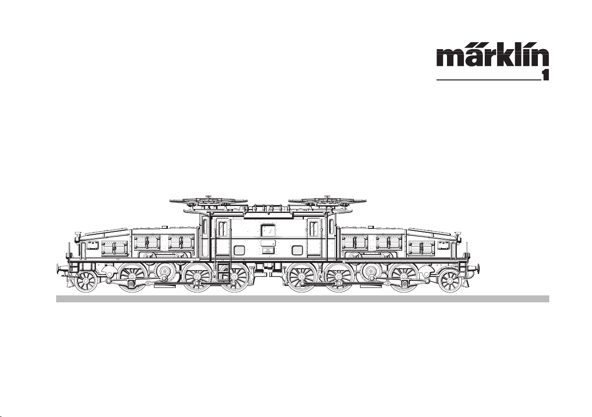
Modell des „Krokodils“ der SBB
Ce 6/8 II - 55562
Page 2
Die Krokodile
Was ist ein Krokodil?
Mit dem Namen dieses exotischen Reptils belegten
Liebhaber die schweren elektrischen Lokomotiven
des Typs Ce 6/8, die in der Schweiz ab 1919 hauptsächlich für die Gotthardstrecke gebaut wurden. Die
Loks sind mittlerweile zum Mythos geworden und haben damit etwas erreicht, was sonst nur Dampflokomotiven vergönnt war: Die Distanz zwischen Mensch
und Maschine schrumpfte.
Nicht nur Eisenbahner, sondern auch Techniker und
Historiker würdigen diese Lokomotiven als Meilen
steine der Technikgeschichte und Symbole für den
Fortschritt. Als die Maschinen gebaut wurden, galten
sie als überzeugende Lösung eines schweren eisenbahntechnischen Problems.
Wann und warum die Loks ihren Spitznamen erhiel
ten, darüber streiten sich die Gelehrten. Ob es die
langen Schnauzen waren, die Kraft, die von ihnen
ausging, die Gelenkigkeit oder gar die Farbe - zunächst braun, später grün -, sie werden es kaum
mehr ergründen können.
Im August 1918 beschlossen die Schweizerischen
Bundesbahnen die Elektrifizierung auf alle verkehrsreichen Strecken ihres Gesamtnetzes auszudehnen.
-
-
Leistungsanforderungen, wie sie die wichtige Gott
hardstrecke an die Maschinen stellte, z.B. zwei Hinund Rückfahrten Arth-Goldau - Chiasso innerhalb von
28 Stunden mit einer Anhängelast von ca. 430 Tonnen
auf Steilrampen und ca. 850 Tonnen auf Talstrecken
mit maximal 10‰Steigung, führten im Güterzugbereich zur Entwicklung des berühmten ,,Krokodils“
Ce 6/8“.
Dieser legendäre Loktyp wurde von 1919-1922 in
33 Einheiten von den Firmen SLM (Schweizerische
Lokomotiv- und Maschinenfabrik Winterthur) und
MFO (Maschinenfabrik Oerlikon) gebaut und an die
SSB ausgeliefert. Technisch zeichneten sich diese
Lokomotiven durch Bissellaufachsen und flachen
Dreieck-Kuppelrahmen als Antriebsorgan aus. Den
Antrieb jedes der beiden Drehgestelle übernahmen je
zwei Motoren, die über Getriebe auf eine gemeinsame
Blindwelle arbeiteten, deren Kurbeln am einen Ende
des Dreieck-Kuppelrahmens eingriffen und am anderen Ende eine Kurbel an einer ursprünglich pendelnd
aufgehängten Hilfswelle bewegten.
Der Hauptvorteil der gewählten Antriebsart lag den
Leistungsanforderungen entsprechend darin, dass im
Gegensatz zum herkömmlichen Schrägstangenantrieb nur Horizontalkräfte von der Vorgelegewelle auf
die Räder übertragen wurde.
Vorbild • Prototype • Exploitation dans le réel • Grootbedrijf
2
-
Page 3

Die Leistung dieses Typs Ce 6/8“ konnte mit 1648 kW
(2240 PS) bei 36 km/h angegeben werden, und die
Höchstgeschwindigkeit betrug 65km/h. Als Dienstgewicht wurden 128 t genannt.
Besondere Ausstattungsmerkmale der historischen
Lokomotive Ce 6/8“, Nr. 14253, die heute noch
regelmäßig zu Sonderfahrten in ihrem Heimatbahn
gebiet Erstfeld (Schweiz) eingesetzt wird, sind neben
der braunen Lackierung für Gehäuse und Vorbauten,
schwarzlackierte Triebwerke, Rahmen und Umläufe
sowie 4 zu öffnende Führerstandstüren.
Den Bremsvorgang besorgten je 2 Klötze pro Treib
achse, die über eine Westinghouse-Druckluft-Doppelbremse oder von Hand bedient werden konnten.
Dabei wirkte die Handbremse pro Führerstand auf
die davor liegenden Treibachsen. Jedes Treibgestell
erhielt zur Erhöhung der Traktion bei Grenzbelastungsfällen je zwei vor und hinter den Treibrädern
eingebaute Sandkästen.
Die bis 1922 von SLM (Schweizerische Lokomotivund Maschinenfabrik Winterthur) und MFO (Maschinenfabrik Oerlikon) gebauten 33 Lokomotiven
des Typs Ce 6/8“ führten jahrelang den schweren
Güterzugdienst am Gotthard durch. Das Bedürfnis
nach leistungsstärkeren und schnelleren Maschinen
-
-
sowie immer häufiger auftretende Störungen an den 4
Fahrmotoren machten jedoch den Umbau eines Teil
bestandes von zunächst 13 Einheiten notwendig. So
wurden in den Jahren von 1942-1947 neben dem Einbau neuer Fahrmotoren und Rahmenverstärkungen
einige Detailveränderungen durchgeführt. Die nicht
umgebauten Lokomotiven wurden sukzessive zum
Rangierdienst in großen Rangieranlagen abgestellt.
Durch Weiterentwicklungen im Elektromotorenbau
konnte eine Mehrleistung (trotz leichterer Motoren)
von 70% erreicht werden. Das bedeutete für den
Einsatz der Maschinen bei den gestiegenen Anforderungen im Gottharddienst einen begrüßenswerten
Zugewinn. Die Leistungsdaten für die nunmehr unter
der Bezeichnung Be 6/8“ laufenden Maschinen konnten jetzt mit 2679 kW (3640PS) bei 45 km/h und die
Höchstgeschwindigkeit mit
75 km/h angegeben werden. Ferner reduzierte sich
das Dienstgewicht um nennenswerte 2t, obwohl ja
einige Änderungsmaßnahmen auf die Verstärkung
von Teilelementen angelegt waren.
-
Vorbild • Prototype • Exploitation dans le réel • Grootbedrijf
3
Page 4

Die Vorbauten erhielten ferner durch Zusatzbalken
vorgesetzte Pufferbohlen, die mit Stangenpuffern alter
Bauart und Übergangsblechen ausgestattet blieben.
Die Blindlagerwellen des SchlitzkuppelstangenAntriebs konnten entgegen der ursprünglich gefederten
Aufhängung nur starr gelagert werden. Die Stirntüren zu
den Umläufen an den Vorbauten wurden verschlossen
und die Türgriffe entfernt. An den vier Führerstandstüren wurde keine Änderung durchgeführt.
Eine weitere Neuerung stellte der Anbau einer Zugheizung mit Stecker, Kabel und Steckdose an beiden
Pufferbohlen dar, denn die Lokomotiven sollten fortan
auch im Personenzugverkehr eingesetzt werden.
Eine Stirnbeleuchtung der Lok mit Fahrberechti
gungssignalisierung, eine Zugsicherung System Signum sowie ein Geschwindigkeitsmesserantrieb und
eine Wachsamkeitskontrolle wurden dadurch ebenso
unumgänglich wie eine erweiterte Bremsausrüstung
mit Regulierbremse.
-
Neben erneuten Veränderungen an der Pufferbohle,
jetzt mit Hülsenpuffern, und dem Wegfall der Übergangsbleche wurden nun auch neue Rangieraufstiege mit breiteren Trittbrettern und doppelläufigen,
gelben Griffstangen angebracht.
Als weitere auffällige Änderung in der Erscheinung
war der Wegfall je einer Führerstandstür mit den
zugehörigen Aufstiegsleitern und Griffstangen, pro
Führerstandseite zu verzeichnen.
Neben wiederkehrenden Messingtafeln für die Hoch
spannungswarnung auf den Vorbauten wurden die
Warntafeln an den doppelwippigen Pantographen
erneut montiert. Sämtliche Aufschriften verblieben in
Gelb oder auf Messingtafeln.
-
Im Zuge der fortschreitenden technischen Entwick
lung und der steigenden Anforderungen im Betrieb
unterlagen die ab 1947 eingesetzten, umgebauten
,,Krokodile“ der Baureihe Be 6/8“ im Laufe der Jahre
weiterer Veränderungsmaßnahmen.
-
Vorbild • Prototype • Exploitation dans le réel • Grootbedrijf
4
Page 5

The Crocodiles
What is a Crocodile?
Enthusiasts applied the name of this exotic reptile
to the type Ce 6/8 heavy electric locomotives which
were built starting in 1919 principally for the Gotthard
line. The locomotives have since then become legendary and have thereby achieved something which
otherwise is only permitted of steam locomotives: The
lessening of the distance between man and machine.
Technicians and historians as well as railroads rate
these locomotives as milestone in the history of technology and symbols of progress. When these units
were built, they were viewed as a persuasive solution
to a difficult problem of railroad technology.
The scholars argue over when and why the locomo
tives were given their nickname. It is most unlikely
that they will ever be able to ascertain whether it was
to long nose pieces, the power from them, the articulated design or even the color - brown at first, green
later.
Because of difficulties in obtaining fuel and supplies,
the Swiss Federal Railroads decided in 1918 to elec
trify all heavily used lines in their network.
-
-
The famous Crocodile Ce 6/8“ evolved because of
the demands required on such lines as the Gotthard
Route, which required two round trips between ArthGoldau and Chiasso within 28 hours while dragging
430 tons uphill and easing 850 tons downhill on
grades not exceeding 10‰.
Two companies, SLM (Swiss Locomotive and Ma
chine Foundry Winterthur) and MFC (Machine Foundry Oerlikon), constructed 33 units of this legendary
engine during the years 1919 -1922. Technical
characteristics of these beauties included its axles
and triangular coupling frames. Each truck was driven
by two motors which transmitted power through a
common hidden shaft whose crank ends were connected at one end with the triangular coupling frame
and the other end with the original swinging auxiliary
axleshaft.
The main advantage of this method was in its performance, since instead of the usual sloping rod
drive, just the horizontal forces of the counter shaft
were transmitted of the wheels.
The Ce 6/8“ was able to maintain 1648 kW (2240hp)
at 36 kmph (21 mph), and had a top running speed of
65 kmph (39 mph). Its service weight was 128 tons.
-
Vorbild • Prototype • Exploitation dans le réel • Grootbedrijf
5
Page 6

No. 14 253 is still used for fan trips out of Erstfeld.
Special markings of this historic model locomotive
Ce 6/8“ are, in addition to the brown paint scheme,
black trucks and frames as well as 4 operating cab
doors.
Braking was done by two sets of brake shoes per
driving axle which are activated either by a Westinghouse air brake or by manual brakes. While the air
brake mechanism controlled all four sets, manual
mechanism controlled only those at either respective
end. For extra traction when pulling heavy loads,
sand boxes were installed at each end.
The 33 locomotives built by SLM and MFO prior to
1922 continued in regular service on the Gotthard
Route. But the ever increasing demands for more
powerful and faster locomotives in addition to the
breakdowns of the 4 motors, prompted the railroad
management to rebuild 13 engines. Thus, during the
years 1942 -1947, the engines also received new
detailing, along with the construction of new motors
and stronger frames. The locomotives not rebuilt were
eventually reassigned to yard duty.
Improvements in electric motor construction resulted
in more powerful motors, even though they were of
lighter weight. In fact, it was rumored to be 70% bet
ter. This, of course, translated into a welcome improvement in the ability to serve the important Gotthard
Route. The new rebuilds were classed Be 6/8“ and
were capable of 2679 kW (3640 hp) at 45 kmph
(23 mph) and had a new top speed of 75 kmph
(45 mph). Service weight was reduced by 2 tons
despite the use of heavier materials in some of the
modifications.
At the ends, an extended platform resulted in diffe
rent bufferplanks, although the older rod buffers and
gangways remained the bearing shaft of the notched
coupling rods could only be positioned rigidly against
the original spring suspension. The doors at either
end leading to the motors were sealed shut and the
door knobs removed. No changes were applied to the
regular cab doors.
An additional modification was the addition of a train
heater with outlets at either end so that the Crocodi
les could be used in passenger service.
-
-
-
Equally indispensable were the headlights, speedome
ter, tail lights, „Signum“ train control system and other
controls as well as the additional braking mechanisms.
Vorbild • Prototype • Exploitation dans le réel • Grootbedrijf
6
-
Page 7

Along with the continued progress in technical developments and the increasing demands exerted on the
Crocodiles after 1947, the Be 6/8“ underwent more
modifications.
Now the locomotives feature newer buffers and the
old gangway plates were removed in favor of switch
men‘s steps with broad plates and twin yellow grab
bars.
In addition, one cab door per cab was removed along
with the hinges and knobs.
-
The warning signs for High Tension were also repla
ced, both on the body and the pantographs. General
reporting marks remained unchanged.
-
Vorbild • Prototype • Exploitation dans le réel • Grootbedrijf
7
Page 8

Les crocodiles
Qu‘ est-ce-qu‘ un crocodile?
Les amis des chemins de fer ont donné le nom de ce
reptile aux lourdes montrices du type Ce 6/8 qui ont
été construites en Suisse pour assurer le trafic marchandises lourd essentiellement sur la ligne du
St Gotthard. Ces motrices sont devenues entretemps
légendaires et, fait unique réversé en général aux
locomotives à vapeur, elles ont réussi à rapprocher
homme et machine.
Les cheminots ainsi que les techniciens et historiens
considèrent à juste titre que ces machines constituent
une étape importante de l’histoire de la technique et
sont devenues un symbole du progrès. Durant la période de construction, ces machines étaient qualifiées
de solution idéale aux problèmes du trafic ferroviaire
lourd.
Quand, et pourquoi ces machines ont-elles reçu leur
surnom. Les savants ne sont pas d’accord pour ré
pondre à cette question. Sont-ce les longs capots ou
la grande puissance qui s’en dégage, est-ce la structure articulée ou même la couleur, initialement brune
puis verte, cette question n’aura jamais de réponse.
-
C’est en août 1918 que les chemins de fer fédéraux
suisses décidèrent d’électrifier toutes les lignes importantes de leur réseau.
Les conditions imposées, sur la ligne du Gotthard,
aux motrices étaient draconiennes: elles devaient
assurer 2 allerretour Arth-Goldau – Chiasso en 28
heures, et cela en tractant environ 430 tonnes sur la
partie en fortes pentes et 850 sur le parties dont le
pentes ne dépassaient pas les 10‰. C’est ainsi que
furent développées les motrices du type „Crocodile“
Ce 6/8II.
Entre 1919 et 1922, les firmes SLM (Schweizerische
Lokomotiv- und Maschinenfabrik Winterthur) et MFO
(Maschinenfabrik Oerlikon) ont livre 33 motrices de ce
type légendaire aux chemins de fer fédéraux suisses.
Du point de vue technique, ces motrices étaient caractérisées par leurs bissels ainsi que par leurs bielles
d’entraînement à structure triangulaire plane. Chaque
bogie moteur à 3 essieux est entraîné par 2 moteurs.
La puissance de ces moteurs est transmise à un
faux-essieu moteurs par l’intermédiaire des bielles à
structure triangulaire. L’extrémité de ce système de
bielles est fixée à une manivelle solidaire d’un essieu
à suspension pendulaire.
Vorbild • Prototype • Exploitation dans le réel • Grootbedrijf
8
Page 9
Le principal avantage de ce système de transmission
résidait dans le fait que les efforts transmis étaient
horizontaux contrairement à la l’ancien système des
bielles obliques.
La puissance de la motrice Ce 6/8II était de
1648 kW (2240 CV) à une vitesse de 36 km/h. Sa
vitesse maxima était de 65 km/h. Son poids en état
de marche était de 128 tonnes.
La motrice historique Ce 6/8II, n° 14253 assure tou
jours des services spéciaux dans la région d’Erstfeld,
sa gare d’attache. Ses caractéristiques particulières
peuvent être résumées comme suit: caisse et capots
laqués brun, embiellage, châssis et passerelles noirs
et 4 portes de cabine.
Le freinage était assuré par 2 sabots de frein par
essieu moteur. Ces sabots étaient actionnés par un
frein Westinghouse à air comprimé et à double effet.
Ils pouvaient également être actionnés à la main.
Dans ce dernier cas, le frein à main d‘une cabine de
conduite n‘agissait cependant que sur les sabots
des essieux situés à l‘avant de la cabine. En outre,
chaque bogie moteur a été doté d‘une caisse à sable
afin de faciliter les démarrages lorsque les conditions
étaient particulièrement difficiles.
-
Les 33 motrices du type Ce 6/8 II ont été construites
par la SLM (Schweizerische Lokomotiv- und Maschinenfabrik Winterthur) et la MFO (Maschinenfabrik
Oerlikon) jusqu‘en 1922. Elles ont assuré pendant
des décennies la traction des trains de marchandises sur la ligne du Gotthard. Mais bientôt le besoin
de motrices plus puissantes et plus rapides se fit
sentir et ceci surtout à cause des pannes de moteur
de plus en plus fréquentes. Il a donc été décidé de
moderniser 13 motrices. Les travaux, exécutés entre
1942 et 1947 consistaient à monter des moteurs de
traction nouveaux et à procéder à des renforcements
du châssis on à profité de ces travaux pour effectuer des transformations de détail. Les motrices non
modernisées furent petit à petit affectées aux grandes
gares de triage pour y effectuer les services de triage
lourds.
Les progrès de la technologie des moteurs électri
ques ont ainsi permi de gagner 70% de puissance, et
ce en utilisant des moteurs plus légers. Ainsi la mise
en service de ces machines sur la ligne du Gotthard
devenait rentable. Les caractéristiques mécaniques
pouvaient être résumées comme suit: Puissance
2679 kw (3 640 CV) à 45 km/h; vitesse maxima
75 km/h. Ces motrices reçurent la nouvelle immatriculation Be 6/8 II; Le poids de ces motrices a été
Vorbild • Prototype • Exploitation dans le réel • Grootbedrijf
9
-
Page 10

réduit de 2 tonnes malgré les renforcements de divers
éléments.
Les capots ont été équipés de poutres supplémentai
res permettant ainsi d‘avancer la traverse porte-tampons. On a par contre maintenu les anciens tampons.
Les faux-essieux entraînant l‘embiellage à fentes ont
eu une suspension rigide. Les portes donnant accès
aux passerelles à partir de la cabine ont été condamnées et les poignées supprimées. Par contre les 4
portes d‘accès aux cabines on été maintenues.
Autre changement: Ces motrices étaient destinées à
assurer également la traction de trains de voyageurs,
d‘où l‘apparition de fiches, câbles et prises sur les
traverses porte-tampons en vue d‘assurer le chauf
fage des trains.
Le service voyageurs nécessita d‘autres installations
de sécurité: feux avec indication de voie libre, sé
curité du type Signum ainsi qu‘un entraînement de
tachymètre et un contrôle d‘ «homme mort». Enfin,
les installations de freinage ont du être développées.
Les motrices du type «Crocodile» de la série Be 6/8II,
mises en service à partir de 1947 ont subi à leur tour
des transformations nécessitées par le trafic toujours
plus important ainsi que par suite des progrès technologiques.
-
-
-
A côte de nouvelles transformations de la traverse
porte-tampons, équipée de nouveaux tampons et de
la suppression des tôles de passage, il convient de
signaler l‘apparition de marche-pieds plus larges ainsi
que de mains-courantes doubles.
Autre transformation apparente: la suppression d‘une
porte d‘accès aux cabines et des marche-pieds cor
respondants de chaque côté.
Les plaques «Haute tension» réapparaissent sur les
capots et au pied des pantographes. Toutes les
inscriptions sont jaunes ou sur plaques de laiton.
Vorbild • Prototype • Exploitation dans le réel • Grootbedrijf
10
-
Page 11

De Krokodillen
Wat is een Krokodil? Liefhebbers hebben de zware
elektrische locomotieven van het type Ce 6/8 met
de naam van dit exotische reptiel gedoopt. Ze zijn in
Zwitserland vanaf 1919 voornamelijk voor de
Gotthardlijn gebouwd. De locs zijn inmiddels tot
mythe verheven en hebben daarmee iets bereikt, wat
anders alleen aan stoomlocomotieven gegund is: de
afstand tussen mens en machine werd minder.
Niet alleen spoorwegmensen, maar ook technici en
historici hebben deze locomotieven als mijlpaal in de
geschiedenis van de techniek en als symbool van de
vooruitgang waardig geacht. Toen de machines gebouwd werden, golden ze als overtuigende oplossing
van een ernstig spoorwegtechnisch probleem.
Over het wanneer en waarom de locs hun bijnaam
kregen, zijn de geleerden het nog niet eens. Of het
de lange snuit was, de kracht die van hen uitging,
de gelede opbouw of zelfs de kleur – eerst bruin,
later groen –, daar kunnen ze nauwelijks meer achter
komen.
Gedwongen door moeilijkheden bij de aanschaffing
van voldoende materiaal en brandstof, besloten de
Zwitserse Spoorwegen (SBB) in augustus 1918 de
electrificatie op alle veel bereden trajecten van hun
gehele spoorwegnet uit te breiden.
Capaciteitsproblemen, welke het belangrijke
Gotthard-traject aan de machines stelde, b.v. twee
heen- en terugritten Arth-Goldau – Chiasso binnen
28 uur met een getrokken last van ca. 430 ton op
steile hellingen en ca. 850 ton op daltrajecten met
maximaal 10‰ steiging, hebben voor het goederenverkeer geleid tot de ontwikkeling van de beroemde
„Krokodillen“ Ce 6/8 II.
Dit legendarische loctype werd van 1919 – 1922 in
33 eenheden gebouwd door de firma‘s SLM (Schweizerische Lokomotiv- und Maschinenfabrik Winterthur)
en MFO (Maschinenfabrik Oerlikon) en aan de SBB
afgele- verd. Technisch onderscheidden zich deze
locomotieven door Bisselloopassen en vlakke driehoek-koppelstangen als aandrijforgaan. De aandrijving van elk van de beide draaistellen werd verzorgd
door elk twee motoren, die via raderwerk op een
gemeenschappelijke tussenas werkten, waarvan de
krukken aan het ene einde van de driehoek-koppelstang lagerden en aan het andere einde een kruk in
bew‘eging bracht aan een oorspronkelijk slingerend
geplaatste hulpas.
Het voornaamste voordeel van de gekozen wijze van
aandrijving lag overeenkomstig de rendementsei
sen daarin, dat in tegenstelling met de gebruikelijke
schuine drijfstangkrachtoverbrenging nu horizontale
Vorbild • Prototype • Exploitation dans le réel • Grootbedrijf
11
-
Page 12

krachten van de tussendrijfas op de wielen werden
overgebracht.
Het vermogen van dit type Ce 6/8II kon met 1648 kW
(2 240 pk) aangegeven worden bij 36 km/u, en de
maximumsnelheid bedroeg 65 km/u. Als dienstgewicht werd 128 t genoemd.
Opvallende details in de uitvoering van de historische
locomotief Ce 6/8II, nr. 14 253, welke heden nog
regelmatig voor speciale ritten wordt inge- zet in het
gebied van zijn thuisstation Erstfeld (Zwitserland), zijn
behalve de bruine kleur voor middenbouw en vooren achteruitbouw, zwartgelakte drijfwerken, freems
en omlopen alsmede 4 opengaande deuren voor de
bestuurderscabines.
Het remmen werd verzorgd door elk 2 remblokken
per drijfas, die via een dubbele Westinghouse-druk
luchtrem of met de hand bediend konden worden.
Daarbij werkte de handrem per bestuurderscabine op
de daarvoor liggende drijfassen. Ieder drijfstel kreeg
ter verhoging van de trekkracht bij grensgevallen van
de belasting elk twee voor en achter de drijfwielen
aangebrachte zandkisten.
De tot 1922 door SLM en MFO gebouwde 33 locomotieven van het type Ce 6/8II namen jarenlang de
zware goederentreindienst over het Gotthard-traject
-
voor hun rekening. De behoefte naar sterkere en snel
lere machines alsmede steeds meer voorkomende
storingen aan de 4 rijmotoren maakten echter het ombouwen van voorloping 13 eenheden noodzakelijk. Zo
werden in de jaren 1942 – 1947 behalve het inbouwen
van nieuwe rijmotoren en freemversterkingen enige
detailwijzigingen doorgevoerd. De niet omgehouwde
locomotieven werden successievelijk voor de rangeerdienst op grote rangeeremplacementen gebruikt.
Door verdere ontwikkelingen bij de bouw van electro
motoren kon een hoger vermogen (niettegenstaande
lichtere motoren) van zegge en schijve 70% worden
bereikt. Dat betekende voor de inzet van de machines
bij toegenomen vervoereisen bij de Gottharddienst
een welkom winstpunt. De vermogensgegevens voor
de sedertdien onder de aanduiding Be 6/8 II rijdende
machines konden nu met 2 679 kW (3 640 pk) bij
45 km/u en de maximumsnelheid met 75 km/u
aangeduid worden. Verder verminderde het dienstgewicht met noemenswaardige 2 t, niettegenstaande
toch enige veranderingen voor de versterking van
bepaalde onderdelen waren doorgevoerd.
De voor- en achteruitbouw kregen verder door extra
balken voorgezette bufferbalken, die met cilinderbuf
fers volgens oud model en overstapplaten bleven
uitgerust. De tussenassen van de sleufkoppelstan-
Vorbild • Prototype • Exploitation dans le réel • Grootbedrijf
12
-
-
-
Page 13

gaandrijving konden in tegenstelling tot de oorspronkelijk geveerde ophanging nu onbeweeglijk gelagerd
worden. De kopdeuren naar de omlopen van de
uitbouw werden dichtgemaakt en de deurkrukken
verwijderd. Aan de vier deuren van de bestuurderscabines werd niets veranderd. Een verdere vernieuwing
is een aansluiting voor treinverwarming met stekers,
draad en stopcontact op beide bufferbalken, want de
locomotieven zouden voortaan ook voor het verkeer
van reizigerstreinen worden ingezet.
Een frontseinverlichting van de loc met het signaleren
van de verkeerstaak, een treinbeveiligingssysteem
Signum alsmede mechanisme voor een snelheidsmeter en een veiligheidscontrole werden daardoor even
onontbeerlijk als een meer uitgebreide remuitrusting
met regelbare remwerking.
In het kader van de voortschrijdende technische
ontwikkeling en de toenemende bedrijfseisen waren
de sedert 1947 ingezette omgebouwde „Krokodillen“
van de serie Be 6/8 II in de loop der jaren aan verdere
wijzigingsmaatregelen onderworpen.
Na nog enige veranderingen aan de bufferbalk, nu met
kokerbuffers en het verwijderen van de overstapplaten
werden nu ook nieuwe rangeeropstappen met bredere
treeplanken en dubbele, gele grijpstangen aangebracht.
Een verdere opvallende verandering in het aanzien
was het wegvallen van een cabinedeur aan iedere
kant met bijbehorende opstapladders en grijpstan
gen.
Behalve de weer teruggekeerde messingplaten met
waarschuwing voor de hoopspanning op voor- en
achteruitbouw, werden de waarschuwingsborden
opnieuw aan de dubbelomklapbare pantografen
bevestigd. Alle opschriften bleven geel of op messingborden.
-
Vorbild • Prototype • Exploitation dans le réel • Grootbedrijf
13
Page 14

Funktion
Diese Lokomotive mit eingebauter Mehrzug-Elektronik bietet:
• Wahlweise Betrieb mit Gleichstrom (max ± 18 V=),
Wechselstrom (Märklin Transformer 32 VA), Märklin Delta
(nur Delta Station 6607), Märklin Digital (nur Control Unit)
oder Märklin Systems (Mobile Station, Central Station).
Ein Betrieb mit anderen Betriebssystemen (Impulsbreitensteuerung, Central Control 1 etc.) ist nicht möglich.
• Die Betriebsart wird automatisch erkannt.
• 80 Mehrzugadressen einstellbar. Adresse ab Werk:
• Mfx-Technologie für Mobile Station / Central Station.
Name ab Werk: Ce 6/8 II
• Veränderbare Anfahrverzögerung/Bremsverzögerung ABV).
• Veränderbare Höchstgeschwindigkeit.
• Veränderbare Lautstärke der Geräusche
• Das Modell ist für den Betrieb auf Märklin 1-Gleisen entwickelt. Ein Betrieb auf anderen Gleissystemen geschieht
auf eigenes Risiko.
• Befahrbarer Mindestradius: 1020 mm
• Märklin Klauenkupplungen vorne und hinten. Bei Verwendung von Kupplungssystemen anderer Hersteller sind
Betriebsprobleme nicht ausgeschlossen.
Die bei normalem Betrieb anfallenden Wartungsarbeiten sind nachfolgend beschrieben. Für Reparaturen
oder Ersatzteile wenden Sie sich bitte an Ihren
Märklin-Fachhändler.
68
Jegliche Garantie-, Gewährleistungs- und Schadensersatzansprüche sind
ausgeschlossen, wenn in Märklin-Produkten nicht von Märklin freigegebene
Fremdteile eingebaut werden und / oder Märklin-Produkte umgebaut werden
und die eingebauten Fremdteile bzw. der Umbau für sodann aufgetretene
Mängel und/ oder Schäden ursächlich war. Die Darlegungs- und Beweislast
dafür, dass der Einbau von Fremdteilen oder der Umbau in bzw. von MärklinProdukten für aufgetretene Mängel und / oder Schäden nicht ursächlich war,
trägt die für den Ein- und / oder Umbau verantwortliche Person und / oder
Firma bzw. der Kunde.
Sicherheitshinweise
• Die Lok darf nur mit einem dafür bestimmten Betriebssystem (Gleichstrom, Märklin Wechselstrom-Transformator 6647, Märklin Delta, Märklin Digital oder Märklin
Systems) eingesetzt werden.
• Die Lok darf nur aus einer Leistungsquelle gleichzeitig
versorgt werden.
• Beachten Sie unbedingt die Sicherheitshinweise in der
Gebrauchsanleitung zu Ihrem Betriebssystem.
• Die Lokomotive darf zwecks Wartungsarbeiten oder
Decoderumstellung nur von Erwachsenen geöffnet werden.
• Keinesfalls Transformatoren für eine Eingangsspannung
von 220 V - für USA 110 V - verwenden
• Vorsicht:
Egal ob das Modell steht oder fährt. Nie mit den
Fingern in das Antriebsgestänge fassen. Es besteht
Quetsch- und Verletzungsgefahr!
14
Betrieb • Operation • Fonctionnement • Exploitatie
Page 15

Schaltbare Funktionen
STOP
mobile station
systems
1
5
central
station
60212
f0
f0f8
f8
60652
6647
Spitzensignal
Führerstandsbeleuchtung
Betriebsgeräusch
Geräusch: Pfeife lang
Rangiergang (nur ABV)
Geräusch: Ankuppeln
Geräusch: Druckluft
Geräusch: Pfeife kurz
Geräusch: Bahnsteigansage
Geräusch: Bremsenquietschen
Geräusch: Lüfter
Geräusch: Luftpresser
Geräusch: Pantograph
Dauernd ein
— f1
— f2
— f3
— f4
— —
— —
— —
— —
— —
— —
— —
— —
Beim Betrieb mit Mobile Station oder Central Station
kann die Anmeldezeit des mfx-Decoders bis zu 2 Minuten
betragen.
6021
function + off
15
Licht-Taste Taste f0 mit Symbol
Taste 1 mit Symbol Taste f1 mit Symbol
Taste 3 mit Symbol Taste f2 mit Symbol
Taste 4 mit Symbol Taste f3 mit Symbol
Taste 2 mit Symbol Taste f4 mit Symbol
Taste 6 mit Symbol Taste f5 mit Symbol
Taste 7 mit Symbol Taste f6 mit Symbol
Taste 5 mit Symbol Taste f7 mit Symbol
Taste 8 ohne Symbol Taste f8 mit Symbol
— Taste f9 mit Symbol
— Taste f10 mit Symbol
— Taste f11 mit Symbol
— Taste f12 mit Symbol
Betrieb • Operation • Fonctionnement • Exploitatie
Page 16

Function
This locomotive has a built-in multi-train electronic
circuit and offers these features:
• Optional operation with DC power (max. ± 18 volts DC),
AC power (with Märklin 32 VA transformer), with Märklin
Delta (only with the 6607 Delta Station), Märklin Digital
(only with the Control Unit), or Märklin Systems (Mobile
Station, Central Station).
• The mode of operation is automatically recognized.
• 80 multi-train addresses can be set. Address that set at
the factory: 68
• Mfx technology for the Mobile Station / Central Station.
Name set at the factory: Ce 6/8 II
• Adjustable acceleration/Braking delay (ABV).
• Adjustable maximum speed.
• Volume can be changed for the sound effects
• The model is designed for operation on Märklin 1 Gauge
track. As the consumer you assume the risk for operating
on other makes of track.
• Minimum radius for operation: 1020 mm / 40-3/16“.
• Märklin claw couplers front and rear. You may have opera
tions problems if you use other makes of couplers.
Maintenance procedures that become necessary with
normal operation of the locomotive are described
below. Please see your authorized Märklin dealer for
repairs or spare parts.
No warranty or damage claims shall be accepted in those cases where parts
neither manufactured nor approved by Märklin have been installed in Märklin
products or where Märklin products have been converted in such a way that
the non-Märklin parts or the conversion were causal to the defects and / or
damage arising. The burden of presenting evidence and the burden of proof
thereof, that the installation of non-Märklin parts or the conversion in or of
Märklin products was not causal to the defects and / or damage arising, is
borne by the person and / or company responsible for the installation and /
or conversion, or by the customer.
Safety Warnings
•
This locomotive is to be used only with an operating
system designed
Märklin Delta, Märklin Digital or Märklin Systems).
• This locomotive must never be supplied with power from
more than one transformer.
•
Pay close attention to the safety warnings in the instructions
for your operating system.
• This locomotive should only be opened by adults for the
purpose of maintenance work or changing the address on
the decoder.
• Under no circumstances should transformers rated for an
input of 220 volts be connected to the American 110 volt
-
household current system.
• Caution:
Regardless of whether model is standing still or in
motion, never grasp the drive rods and valve gear with
your fingers. You may possibly pinch and injure your
fingers!
for it (Märklin 6646/6647 AC transformer,
16
Betrieb • Operation • Fonctionnement • Exploitatie
Page 17

Controllable Functions
STOP
mobile station
systems
1
5
central
station
60212
f0
f0f8
f8
60652
6647
Headlights/marker lights
Engineer‘s cab lighting
Operating sounds
Sound effect: long whistle blast
Switching range (only ABV)
Sound : locomotive coupling up to train
Sound:
compressed air
Sound effect: short whistle blast
Sound:
station platform announcements
Sound: brakes squealing
Sound: blower motor
Sound: air pump
Sound effect: pantograph
Continuously on
The registration time for the mfx decoder can last up
to 2 minutes, when you are running the locomotive
with the Mobile Station or the Central Station.
6021
function + off
— f2
— f3
— f4
— —
— —
— —
— —
— —
— —
— —
— —
17
Headlight button Button f0 with symbol
f1
Button 1 with symbol Button f1 with symbol
Button 3 with symbol Button f2 with symbol
Button 4 with symbol Button f3 with symbol
Button 2 with symbol Button f4 with symbol
Button 6 with symbol Button f5 with symbol
Button 7 with symbol Button f6 with symbol
Button 5 with symbol Button f7 with symbol
Button 8 without symbol Button f8 with symbol
Button f9 with symbol
— Button f10 with symbol
— Button f11 with symbol
— Button f12 with symbol
Betrieb • Operation • Fonctionnement • Exploitatie
Page 18

Fonctionnement
Cette locomotive possède un équipement électronique pour conduite multitrain:
• Au choix, exploitation conventionnelle avec courant continu
(max ± 18 volts =), Courant alternatif (Transformer 32 VA), ex
ploitation avec Märklin Delta (uniquement Delta Station 6607),
Märklin Digital (uniquement Control Unit) ou Märklin
(Mobile Station ou Central Station). Une exploitation
d’autres systèmes d’exploitation (courant à largeur d’impulsion
variable, Central Control 1, etc.) n’est pas possible.
• Le mode d’exploitation est automatiquement détecté.
• 80 adresses pour conduite multitrain sont disponibles.
Adresse réglée en usine: 68
Systems
avec
• Technologie mfx pour Mobile Station / Central Station.
Nom en codee en usine: Ce 6/8 II
• Temporisation d’accélération/de freinage réglable (ABV).
• Vitesse maximale réglable.
• Le modèle réduit est conçu pour rouler sur des voies Märklin
1. Le faire rouler sur des voies d’autres systèmes comporte
des risques.
• Rayon minimal d’inscription en courbe: 1020 mm.
• Attelages à griffe Märklin avant et arrière. En
d’un système provenant d’un autre fabricant,
sont susceptibles de survenir.
cas d’utilisation
des problèmes
Les travaux d‘entretien occasionnels à effectuer en
exploitation normale sont décrits plus loin. Pour toute
réparation ou remplacement de pièces, adressezvous à votre détaillant-spécialiste Märklin.
-
Tout recours à une garantie commerciale ou contractuelle ou à une demande de
dommages-intérêt est exclu si des pièces non autorisées par Märklin sont inté
grées dans les produits Märklin et / ou si les produits Märklin sont transformés
et que les pièces d’autres fabricants montées ou la transformation constituent
la cause des défauts et / ou dommages apparus. C’est à la personne et / ou la
société responsable du montage / de la transformation ou au client qu’incombe
la charge de prouver que le montage des pièces d’autres fabricants sur des
produits Märklin ou la transformation des produits Märklin n’est pas à l’origine
des défauts et ou dommages apparus.
Remarques importantes sur la sécurité
• La locomotive ne peut être mise en service qu’avec un
système d’exploitation adéquat (Märklin courant alternatif
-transformateur 6647, Märklin Delta, Märklin Digital ou
Märklin Systems).
• La locomotive ne peut être alimentée en courant que par une
seule source de courant.
• Veuillez impérativement respecter les remarques sur la
sécurité décrites dans le mode d’emploi en ce qui concerne le
système d’exploitation.
• Pour l’entretien ou et les modifications relatives au décodeur,
la locomotive doit être ouverte exclusivement par des adultes.
• N’utilisez en aucun cas de transformateurs pour une tension à
l’entrée de 220 V - 110 V pour les Etats-Unis.
• Attention :
Que le modèle soit arrêté ou qu‘il roule, ne jamais
mettre les doigts dans le mécanisme d‘entraînement.
Risque
18
d‘écrasement et de blessure !
Betrieb • Operation • Fonctionnement • Exploitatie
-
Page 19

Fonctions commutables
STOP
mobile station
systems
1
5
central
station
60212
f0
f0f8
f8
60652
6647
Fanal éclairage Permanence
Eclairage de la cabine de conduite
Bruit d’exploitation
Bruitage : sifflet long
Vitesse de manœuvre (seulement ABV)
Bruitage : Attelage
Bruitage :
air comprimé
Bruitage : sifflet
Bruitage :
Annonce de quai
Bruitage : Grincement de frein
Bruitage : Ventilateur
Bruitage : Compresseur de frein
Bruitage: pantographe
Lors de l’exploitation avec Mobile Station ou Central
Station, le temps de réponse du décodeur mfx peut
durer jusqu’à 2 minutes.
6021
function + off
— f1
— f2
— f3
— f4
— —
— —
— —
— —
— —
— —
— —
— —
19
Touche Lumière Touche f0 avec symbole
Touche 1 avec symbole Touche f1 avec symbole
Touche 3 avec symbole Touche f2 avec symbole
Touche 4 avec symbole Touche f3 avec symbole
Touche 2 avec symbole Touche f4 avec symbole
Touche 6 avec symbole Touche f5 avec symbole
Touche 7 avec symbole Touche f6 avec symbole
Touche 5 avec symbole Touche f7 avec symbole
Touche 8 sans symbole Touche f8 avec symbole
— Touche f9 avec symbole
— Touche f10 avec symbole
— Touche f11 avec symbole
— Touche f12 avec symbole
Betrieb • Operation • Fonctionnement • Exploitatie
Page 20

Werking
Deze loc met ingebouwde digitaalelektronica biedt u:
• Naar keuze conventioneel bedrijf (wisselstroom met de
Transformer 32 VA of gelijkstroom [max +/– 18 Volt=] ),
bedrijf met Märklin Delta (alleen het Delta Station 6607),
Märklin Digital (Control Unit) of het Märklin Systems (Mo
bile Station of Central Station). Het bedrijf met rijregelaars
van andere systemen (bijv. impulsbreedte sturing, gebruik
van de Central-Control 1 (6030) of een dergelijk systeem)
is niet mogelijk.
• Het bedrijfssysteem wordt automatisch herkend.
• 80 meertreinen-adressen instelbaar. Ingesteld adres vanaf
de fabriek: 68
• Mfx-technologie voor het Mobile Station / Central Station.
Naam af de fabriek: Ce 6/8 II
• Instelbare optrekvertraging/afremvertraging.
• Instelbare maximumsnelheid.
• Het model is ontwikkeld voor het gebruik op het Märklin
Spoor 1 railsysteem. Het gebruik op een ander railsysteem geschied op eigen risico.
• Berijdbare minimumradius: 1020 mm.
• Voor en achter, Märklin klauwkoppelingen. Bij het gebruik
van koppelingssystemen van andere fabrikanten zijn sto
ringen niet uit te sluiten.
De in het normale bedrijf voorkomende onderhoudswerkzaamheden zijn verderop beschreven. Voor
reparatie of onderdelen kunt u zich tot uw Märklin
winkelier wenden.
-
-
Elke aanspraak op garantie en schadevergoeding is uitgesloten, wanneer in
Märklin-producten niet door Märklin vrijgegeven vreemde onderdelen inge
bouwd en / of Märklin-producten omgebouwd worden en de ingebouwde
vreemde onderdelen resp. de ombouw oorzaak van nadien opgetreden
defecten en / of schade was. De aantoonplicht en de bewijslijst daaromtrent,
dat de inbouw van vreemde onderdelen in Märklin-producten of de ombouw
van Märklin-producten niet de oorzaak van opgetreden defecten en / of
schade is geweest, berust bij de voor de inbouw en/of ombouw verantwoordelijke persoon en / of firma danwel bij de klant.
-
Veiligheidsvoorschriften
• De loc mag alleen met een daarvoor bestemd bedrjfssysteem (Märklin wisselstroom transformator 6647,
Märklin Delta, Märklin digitaal of Märklin Systems)
gebruikt worden.
• De loc mag niet vanuit meer dan één stroomvoorziening
gelijktijdig gevoed worden.
• Lees ook aandachtig de veiligheidsvoorschriften in de
gebruiksaanwijzing van uw bedrijfssysteem.
• De locomotief mag, voor onderhoudswerkzaamheden
of het wijzigen van de decoderinstellingen, alleen door
volwassenen geopend worden.
• In geen geval transformatoren met een ingangsspanning
van 220 V - voor USA 110 V - gebruiken.
• Voorzichtig:
ongeacht of het model stilstaat of rijdt. Nooit met de
vingers aan de aandrijfstangen komen. Er bestaat
gevaar voor kneuzingen of verwondingen!
-
20
Betrieb • Operation • Fonctionnement • Exploitatie
Page 21

Schakelbare functies
STOP
mobile station
systems
1
5
central
station
60212
f0
f0f8
f8
60652
6647
Frontsein
Cabineverlichting
Bedrijfsgeluid
Geluid: fluit lang
Rangeerstand (alleen optrek- afremvertr.)
Geluid: aankoppelen
Geluid: vertrekfluit
Geluid: fluit
Geluid: stationsomroep
Geluid: piepende remmen
Geluid: ventilator
Geluid: compressor
Geluid: pantograaf
continu aan functie + off
Bij het bedrijf met het Mobile Station of het Central
Station kan het aanmelden van de mfx-decoder ca. 2
minuten duren.
6021
— f1
— f2
— f3
— f4
— —
— —
— —
— —
— —
— —
— —
— —
21
verlichtingstoets Toets f0 met symbool
Toets 1 met symbool Toets f1 met symbool
Toets 3 met symbool Toets f2 met symbool
Toets 4 met symbool Toets f3 met symbool
Toets 2 met symbool Toets f4 met symbool
Toets 6 met symbool Toets f5 met symbool
Toets 7 met symbool Toets f6 met symbool
Toets 5 met symbool Toets f7 met symbool
Toets 8 zonder symbool Toets f8 met symbool
— Toets f9 met symbool
— Toets f10 met symbool
— Toets f11 met symbool
— Toets f12 met symbool
Betrieb • Operation • Fonctionnement • Exploitatie
Page 22

Anschluss der Gleisanlage
Um Spannungsverluste auf der
Anlage zu vermeiden ist
immer auf gutes Zusammenpassen der Schienenverbindungslaschen zu achten.
Alle 2 bis 3 m ist eine neue
Stromeinspeisung über die
Anschlussklemmen 5654 empfehlenswert.
Befahren von Steigungen
Im Gegensatz zum Vorbild können mit einer Modellbahn auch
größere Steigungen befahren
werden. Im Normalfall sollte
eine Steigung bei maximal 3
Prozent liegen. Im Extremfall sind bei entsprechend
eingeschränkter Zugleistung
maximal 5 Prozent möglich.
Der Anfang und das Ende der
Steigung sind auf jeden Fall
auszurunden.
Der Unterschied in der Steigung zwischen zwei mindestens 300 mm langen Gleisstücken darf maximal 1 bis 1,5
Prozent betragen.
Connections between
the track layout and the
transformer
Rail joiners must fit well on the
rails of the track to which they
are joined to avoid voltage drop
on the layout. We recommend
that you install feeder wires
every 2 to 3 meters (7 to 10
feet) using the 5654 feeder
clips.
Operating the locomotive
on grades
In contrast to the prototype
locomotive on a model railroad
can operate up steeper grades.
As a general rule a grade
should be no steeper than 3%.
In extreme situations a maximum grade of 5% is permissible, keeping in mind that the
locomotive’s tractive effort will
be less. The beginning and the
end of the grade must always
work gradually up to maximum grade for the route. The
maximum allowable difference
in grade between two track
sections, each with a minimum
length of 300 mm (11-3/4“) is 1
to 1.5 percent.
a
Connexion des voies
ferrées
Pour éviter des pertes de
potentiel sur l’installation, il faut
veiller à ce que les éclisses de
liaison des rails soient toujours
parfaitement adaptées. Une
nouvelle alimentation électrique est conseillée tous les
2 à 3 m au moyen des griffes
d’alimentation 5654.
Franchissement des côtes
Contrairement à l’original, la
maquette est également en
mesure de franchir des côtes
assez importantes. En temps
normal, une côte devrait étre
de l’ordre de 3% maximum.
A l’extrême limite, 5% sont
envisageables avec une
puissance du train réduite en
consequence. Le début et la fin
de la côte doivent en tous cas
étre arrondis.
La différence de pente
entre deux éléments de voie
d’au moins 300 mm de longueur doit étre de 1 à 1,5%
maximum.
Aansluiting van de sporen
Om spanningsverlies op de
modelbaan te voorkomen
moeten de raillassen altijd goed
op elkaar aansluiten. Om de 2 à
3 meter moet de voeding opnieuw op de rails gezet worden.
Daarbij zijn de aansluitklemmen
5654 aan te raden.
Berijden van hellingen
In tegenstelling tot het grote
voorbeeld kunnen met een
modelbaan ook grotere hellingen bereden worden. Normaal
moet een helling maximaal
3 procent zijn.
gevallen is maximaal 5 procent
mogelijk, maar
ning gehouden worden met een
evenredig verlies aan vermogen. Het begin en het einde
van de helling moeten altijd
gerond worden.
Het verschil in de helling tussen
twee tenminste 300 mm lange
railstukken mag maximaal 1 à
1,5 procent bedragen.
In extreme
dan moet reke-
22
Betrieb • Operation • Fonctionnement • Exploitatie
Page 23

Lokparameter einstellen mit der Control Unit
1.
Voraussetzung: Aufbau wie
Grafik S. 24. Nur die zu verändernde Lok ist auf dem Gleis.
2. „Stop“- und „Go“-Taste
gleichzeitig drücken, bis „99“
in der Anzeige aufblinkt.
3. „Stop“-Taste drücken.
4. Lokadresse „80“ eingeben.
5.
Umschaltbefehl am Fahrregler halten.
tens die „Go“-Taste drücken.
6. Licht der Lok blinkt lang
sam. Wenn nicht, ab Schritt
2 wiederholen.
7.
Registernummer für den zu
ändernden Parameter eingeben (=> Liste auf Seite 26).
8.
Fahrtrichtungswechsel betätigen.
9. Licht blinkt schnell
10. Neuen Wert eingeben (=>
Liste auf Seite 26).
11.
Fahrtrichtungswechsel betätigen.
12. Licht blinkt langsam (Ausnahme Werkreset)
13.
Nächste Parametereinstellung
ab 6. oder beenden mit 14.
14. Vorgang beenden mit
Drücken der „Stop“-Taste.
Anschließend Drücken der
„Go“-Taste.
Während des Hal-
-
Setting Locomotive Parameters with the Control Unit
1.
Requirement: Setup as in diagram
on page 24. Only the locomotive
to be changed can be on the
track.
2. Press the “Stop” and “Go” at the same
time until “99” blinks in the display.
3. Press the “Stop” button.
4.
Enter the locomotive address „80“
.
5. Hold the control knob in the
reverse direction area. While
holding the control knob here,
press the „Go“ button.
6. The headlights on the locomotive will blink slowly. If they don‘t,
repeat Step 2.
7. Enter the register number for the
parameter to be changed (=>
List on page 26).
8.
Active the change of direction
9.
The headlights will blink rapidly.
.
10.Enter the new value (=>List on
page 26).
11.
Active the change of direction.
12.
The headlights will blink slowly
(exception: factory reset)
13.Enter the next parameter setting from
6 or end with 14.
14.End the process by pressing the
„Stop“ button. Then press the
„Go“ button.
23
Réglage des paramètres
de la loco avec la
Control Unit
1. Condition: Montage comme sur
illustration en page 24. Seule la
loco à modifier peut se trouver sur
la voie.
2. Pressez simultanément les touches
„Stop“ et „Go“ jusqu’à ce que le
nombre „99“ clignote sur l’écran.
3. Pressez la touche „Stop“.
4. Introduisez l’adresse de loco „80“.
5.
Maintenir l’ordre de commutation sur
le régulateur de marche. Durant le
maintien, appuyer sur la touche „Go“.
6. Les feux de la locomotive clignotent lentement. Dans le cas contraire, renouveler l’opération à partir
de l’étape 2.
7. Indiquer le numéro ’enregistrement
pour le paramètre à modifier (=>
liste page 26).
8.
Activer l’inversion du sens de marche.
9. Les feux clignotent rapidement.
10.
Entrer la nouvelle valeur (=> liste page 26).
11. Activer l’inversion du sens de marche.
12. Les feux clignotent lentement
(exception : réinitialisation aux
valeurs d’usine)
13.
Définition de paramètres suivante à par-
tir du point 6 ou terminer par le point 14.
14. Terminez le processus en pressant
la touche „Stop“. Ensuite, pressez
la touche „Go“.
Betrieb • Operation • Fonctionnement • Exploitatie
Locparameters instellen met de Control Unit
1. Voorwaarde: opbouw zoals tekening op pagina 24. Alleen de loc die
gewijzigd moet worden op de rails.
2. ”Stop”- en ”Go”-toets gelijktijdig
indrukken tot ”99” in het display
oplicht.
3. ”Stop”-toets indrukken.
4. Het adres „80“ invoeren.
5. Omschakelcommando met de
rijregelaar vasthouden. Tijdens
het vasthouden de toets “Go”
indrukken.
6. De verlichting van de loc knippert langzaam. Indien dit niet het
geval is, vanaf stap 2 opnieuw
beginnen.
7. Het registernummer van de te
wijzigen parameter invoeren
(=> lijst op pagina 26).
8. Omschakelcommando geven.
9. Verlichting gaat snel knipperen.
10. Nieuwe waarde invoeren (=>
lijst op pagina 26).
11. Omschakelcommando geven.
12. Verlichting knippert langzaam
(uitgezonderd bij decoder reset)
13. Volgende parameterinstelling
of beëindigen met 14
14. Sessie beëindigen door het
indrukken van de toets “Stop”.
Aansluitend de toets “Go”
indrukken.
Page 24

Lokparameter mit Control Unit ändern.
Changing Locomotive Parameters with the Control Unit.
Modification des paramètres avec la Control Unit.
Locparameter met de Control Unit.
Modificar los parámetros de la locomotora con el Control Unit.
Modifica dei parametri della locomotiva con la Control Unit.
Lokparametrar ändras med Control Unit.
Ændring af lokomotivparametre med Control Unit.
24
Betrieb • Operation • Fonctionnement • Exploitatie
Page 25

1
80
1
Lokparameter verändern mit der Control Unit 6021.
1
1
99
1
2
80
2
1
01
01
1
1
2
10
10
1
11
14
12
Changing Locomotive Parameters with the 6021 Control Unit.
Modification des paramètres de la locomotive avec la Control Unit 6021.
Locparameter wijzigen met de Control Unit.
Modificar los parámetros de la locomotora con el Control Unit 6021.
Modifica dei parametri della locomotiva con la Control Unit 6021.
Lokparametrar ändras med Control Unit 6021.
Ændring af lokomotivparametre med Control Unit 6021.
25
Betrieb • Operation • Fonctionnement • Exploitatie
Page 26

Parameter • Parameter • Paramètre • Parameter •
Parámetro • Parametro • Parameter • Parameter
Register • Register •
Registre • Register •
Registro • Registro •
Register • Register
Wert • Value • Valeur
• Waarde • Valor •
Valore • Värde •
Værdi
Adresse • Address • Adresse • Adres • Código • Indrizzo •
Adress • Adresse
Anfahrverzögerung • Acceleration delay • Temoprisation
accélération • Optrekvertraging • Regulación arranque •
Ritardo di avviamento • Igångsättningsreglering •
Opstartregulierung
Bremsverzögerung • Braking delay • Temporisation de freinage • Afremvertraging • Frenado lento • Ritardo di frentura •
Bromsfördröjning • Bremseforsinkelse
Höchstgeschwindigkeit • Maximum speed •
Vitesse maximale • Maximumsneilheid • Velocidad máxima •
Velocità massima • Toppfart • Maksimalhastighed
Vmax: CS 125 MS 49 %
Rückstellen auf Serienwerte • Reset to series value • Remettre
aux valeurs de série • Terugzetten naar serie-instellingen •
Restablecer los valores de serie • Pipristinare sui valori di serie
• Återställa till standardvärden • Tibagestil til serieværdien
Lautstärke • Volume • Volume haut-parleur • Volume •
Volumen del sonido • Intensit à sonara • Ljudstyrka
Lydstyrke MS: 72 %
26
01 - 8001
01 - 6303
01 - 6304
01 - 6305
0808
63 01 - 63
Betrieb • Operation • Fonctionnement • Exploitatie
Page 27

Betrieb mit Mobile Station / Central Station
• Lok aufgleisen. Die Lok meldet sich selbsttätig in der
Lokliste an.
• Keine Rückmeldung der Lok, wenn:
bei Mobile Station der Geschwindigkeitsbalken blinkt
bei Central Station das mfx-Symbol unterstrichen ist
• Lok abmelden:
1. Lok vom Gleis entfernen.
2. Lokeintrag löschen.
Eine Adressänderung ist nicht notwendig.
Lokparameter mit der Mobile Station / Central
Station verändern
1. Lok aus der Lokliste auswählen.
2. Zum Untermenü „LOKÄNDERN“ wechseln.
3. Zum Untermenü „VMAX“ (Höchstgeschwindigkeit),
„ACC“ (Beschleunigung), „DEC“ (Bremsen),
„VOL“ (Lautstärke) oder
„RESET“ (Decoder auf Werkeinstellung zurück) wechseln.
4. Neuen Wert eingeben und übernehmen.
Beachten Sie die Hinweise in der Anleitung zur Mobile
Station / Central Station.
Operation with the Mobile Station / Central Station
• Set the locomotive on the track. The locomotive automatically registers itself in the locomotive list.
• The locomotive will not communicate back to the control
ler when:
the speed bar on the Mobile Station blinks.
the mfx symbol has a line beneath it on the Central Station.
• Taking the locomotive out of the locomotive list:
1. Remove the locomotive from the track.
2. Delete the locomotive entry.
It is not necessary to change the address.
Changing Locomotive Parameters with the
Mobile Station
1. Select the locomotive from the locomotive list.
2. Change to the submenu “EDIT LOC”.
3. Go to the submenu „VMAX“ (maximum speed),
„ACC“ (acceleration), „DEC“ (brakes),
„VOL“ (volume) or
„RESET“ (resetting the decoder to factory default settings)
4. Enter the new value and accept it into the system.
.
Please note the information in the instructions for the
Mobile Station / Central Station.
-
27
Betrieb • Operation • Fonctionnement • Exploitatie
Page 28

Exploitation avec Mobile Station / Central Station
• Enrailler la locomotive. La locomotive signale automatiquement sa présence dans la liste des locos.
• Pas de rétrosignalisation de la locomotive lorsque :
- la barre de vitesse clignote pour Mobile Station
- le symbole mfx est souligné pour Central Station
• Appeler loco:
1. Enlever loco de la voie.
2. Effacer entrée loco.
Une modification de l’adresse n’est pas nécessaire.
Bedrijf met Mobile Station / Central Station
• Loc op de rails plaatsen. De loc meldt zichzelf aan in de
loclijst.
• Geen terugmelding van de loc als:
bij het Mobile Station de snelheidsbalk knippert
bij het Central Station het mfx-symbool onderstreept is
• Loc afmelden:
1. loc van de rails nemen
2. loc invoer wissen.
Het wijzigen van het adres is niet nodig.
Modification des paramètres de la loco avec la
Mobile Station/Central Station
1. Sélectionnez la loco dans la liste.
2. Allez au sous-menu „MODIF LOC“.
3. Ouvrir le sous-menu « VMAX » (vitesse maximale),
« ACC » (accélération), « DEC » (freinage),
« VOL » (volume) ou
« RESET » (réinitialisation du décodeur aux valeurs d’usine).
4. Entrez la nouvelle valeur et acceptez.
Respectez les remarques mentionnées dans
l’instruction accompagnant la Mobile Station / Central
Station.
Locparameter wijzigen met het Mobile Station/
Central Station
1. Loc uit de loclijst kiezen.
2. Ga naar het nevenmenu ”WIJZIG LOC”.
3. Naar het nevenmenu “VMAX” (maximumsnelheid)
“ACC” (optrekken), “DEC” (afremmen),
“VOL” (volume) of
“RESET” (decoder terugzetten naar fabrieksinstelling)
omschakelen.
4. Nieuwe waarde invoeren en overnemen.
Lees ook de opmerkingen in de gebruiksaanwijzing
van het Mobile Station / Central Station.
28
Betrieb • Operation • Fonctionnement • Exploitatie
Page 29

Pflegehinweis
Diese Lok kann auch im
Außenbereich eingesetzt
werden. Ein Betrieb bei
schlechten Witterungsbedingungen (Schnee oder
Regen) wird nicht empfohlen.
Antrieb und Elektronik sind
gegen Spritzwasser geschützt. Wasserdurchfahrten sind nicht möglich.
Es wird empfohlen, das
Modell nach dem Betrieb
im Außenbereich auf Verschmutzung zu prüfen und
gegebenenfalls trocken mit
Staubtuch oder Pinsel zu
reinigen. Nie die Lok unter
fließendem Wasser reinigen.
Hinweis: Reinigungsmittel
können die Farbgebung
oder die Beschriftung der
Lok angreifen und beschä
digen.
-
Tips For The Care Of
Your Locomotive
This locomotive can also
be used outdoors. We do
not recommend running the
locomotive in bad weather
(snow or rain).
The mechanism and the
electronic circuit are protected against spraying water.
The locomotive cannot be
run through water.
We recommend that you
check the locomotive over
after running in outdoors
and that you dry it with
a cloth or clean in with a
brush if necessary. Never
clean the locomotive with
running water.
Important: Cleaning fluids
can attack the finish and
lettering for the locomotive
and damage them.
Remarque sur
l’entretien
Cette locomotive peut également être mise en service
à l’air libre. Une utilisation
par mauvais temps (neige
ou pluie) n’est pas recommandée.
Le moteur et l’électro-nique sont protégés contre
les projections d’eau. Des
trajets dans l’eau ne sont
pas possibles.
Il est recommandé de
vérifier l’encrassement du
modèle après une utilisation à l’extérieur et, le cas
échéant, de nettoyer le
modèle à l’aide d’un chiffon
doux ou un pinceau. Ne
jamais nettoyer le modèle
au jet d’eau.
Attention: Certains solvants
et produits d’entretien peu
vent altérer le marquage et
la peinture du modèle.
Opmerkingen voor het
onderhoud
Deze loc kan ook buiten gebruikt worden. Het gebruik
bij slecht weer (sneeuw of
regen) is niet aan te raden.
Aandrijving en elektronica
zijn weliswaar afgeschermd
tegen spatwater maar
rijden door het water is niet
mogelijk.
Het is aan te bevelen het
model na het gebruik buiten
te controleren op vuil en dit
eventueel droog te verwijderen met een stofdoek of
een zachte kwast. Nooit de
loc onder stromend water
reinigen.
Opmerking: reinigingsmiddelen kunnen de lak en
de opschriften op de loc
aantasten en beschadigen.
-
29
Wartung • Maintenance • Entretien • Onderhoud
Page 30

Zum Auspacken die
Lokomotive stets mit
2 Händen greifen, wie
unten dargestellt.
Always grasp the locomotive with both
hands to take it out of
its packaging, as shown
below.
Pour le déballage,
toujours manipuler la
locomotive avec les deux
mains, tel que décrit cidessous.
Bij het uitpakken de
locomotief steeds met
beide handen beetpakken zoals onderstaand
weergegeven.
30
Wartung • Maintenance • Entretien • Onderhoud
Page 31

5.
2.
1.
4.
3.
9.
8.
6.
7.
Kupplung austauschen
Beim Aufstellen der
Lokomotive als Vitrinenmodell können die automatischen Kupplungen
entfernt werden. Mit den
beiliegenden Schraubkupplungen und Bremsschläuchen kommt diese
Lokomotive als Vitrinenmodell erst richtig zur
Geltung.
Remplacement des
attelages
Si vous voulez exposer
votre locomotive dans
une vitrine, vous pouvez
démonter les chrochets
automatiques.
Avec les attelages à vis
et les boyaux de frein
fournis, cette locomotive
Koppelingen verwisselen
Bij het opstellen van de
locomotief als vitrinemodel kunnen de automatische koppelingen
worden verwijderd.
Met de meegeleverde
schroefkoppeling en
remslangen komt deze
locomotief als vitrinemodel
echt tot zijn recht.
Changing couplings
The automatic couplers
can be removed if the
locomotive is to be used
as a static display. This
locomotive really comes
into its own as a display
model with the reproduction prototype couplers
and brake hoses that are
included with it.
sera parfaitement mise
en valeur comme modèle
d’exposition.
31
Wartung • Maintenance • Entretien • Onderhoud
Page 32

Aufsetzen der Lokomotive bei Oberleitungsbetrieb
Die Lokomotive muss
mit der markierten Seite
auf der Schiene stehen,
die den Rückleiter für die
Oberleitung bildet. An
diese Schiene ist am Anschlussgleis das braune
Kabel zum Fahrgerät gemeinsam mit der Unterleitung angeschlossen.
Mit 2 Fahrgeräten ist so
ein unabhängiger 2-Zugbetrieb auf dem gleichen
Gleis möglich, wenn eine
Lokomotive auf „Oberleitung“ und die andere auf
„Unterleitung“ geschaltet
ist.
Setting up the locomotive for overhead line
operation
The locomotive must
stand with the marked
side on the rail which
forms the return for the
overhead line. The brown
lead wire to the driving
unit is locked together
with the undercontact rail
to this rail at the branch
track.
With 2 driving units, such
an independent 2nd train
operation on the same
track is possible if one
locomotive is switched
to “overhead line” and
the other to “under-contact rail”.
Mise en voie de la motrice en cas d‘alimentation
par ligne aérienne
La motrice doit être placée sur la voie de façon
telle que le côté marqué
soit du côte du rail qui
assure le retour du courant de la caténaire. Vous
pouvez repérer ce rail à
l‘élément de voie prise
de courant. C‘est en effet
le rail auquel est soudé le
câble brun qui assue le
retour du courant tant de
la ligne aérienne que de
l‘alimentation par rails.
On peut ainsi assurer sur
une voie donnée un trafic
de 2 trains indépendants.
Dans ce cas l‘une des
motrices est alimentée
par caténaire, l‘autre par
les rails.
Op de rails plaatsen van
de locomotief bij het
rijden via bovenleiding
De locomotief moet
med de gemerkte kant
op de railstaaf staan,
die de terugleiding voor
de bovenleiding vormt.
Aan deze railstaaf is bij
de aansluitrail de bruine
draad naar transformator
of regelaar gezamenlijk
met de benedenleiding
verbonden.
Met 2 trafo‘s resp. rege
laars is zo een onafhankelijk tweede treinverkeer
op hetzelfde spoor mogelijk, als een locomotief
op „bovenleiding” en de
andere op „benedenleiding” geschakeld is.
-
32
Wartung • Maintenance • Entretien • Onderhoud
Page 33

33
Wartung • Maintenance • Entretien • Onderhoud
Page 34

2.
1.
1.
3.
2.
Mittelgehäuse abnehmen
Remove center housing
Démonter la caisse centrale
Middelste kap afnemen
Vorbaugehäuse abnehmen
Remove front housing
Retirer les capots
Kap uitbouw afnemen
34
Wartung • Maintenance • Entretien • Onderhoud
Page 35

Schmierung
Die Lokomotive sollte vor
der ersten Inbetriebnahme, das zweite Mal nach
20 Betriebsstunden, das
dritte Mal nach ca. 50
Betriebsstunden und
dann alle 100 Betriebsstunden geölt werden.
Lubrication
The locomotive should
be oiled before operating it for the first time,
after the first 30 hours
of operation and then
after every 100 hours of
operation.
Graissage
Graisser la locomotive
avant la première mise
en marche, procéder à
un 20 graissage après
30 heures de fonctionnement, puis après 50 heures et ensuite toutes les
100 heures de marche.
TRIX 66626
Smering
De smeerbeurten van de
locomotief dienen te geschieden voor de eerste
rit, de tweede keer na 30
bedrijfsuren, de derde
keer na ca. 50 en daarna
bij alle 100 bedrijfsuren.
35
Wartung • Maintenance • Entretien • Onderhoud
Page 36

Haftreifen wechseln
1.
2.
Changing non-skid tires
Remplacement des bandages adhérents
Nieuwe antislipbanden omleggen
36
Wartung • Maintenance • Entretien • Onderhoud
Page 37

Glühlampen austauschen
Schleifer wechseln
Changing light bulbs
Remplacement des ampoules
Nieuw lampje inzetten
Changing pick-up shoes
Remplacement des frotteurs
Nieuwe sleepcontacten aanbrengen
37
Wartung • Maintenance • Entretien • Onderhoud
Page 38

2
5
6
10
9
4
14
12
4
11
16
7
8
14
14
15
23
24
21
20
22
19
26
29
28
30
19
19
3
13
1
19
19
17
25
27
24
31
18
35
34
33
32
35
25
25
36
37
393938
41
40
42
37
46
45
43
49
47
48
50
51
52
54
55
595857
56
53
60
62
61
61
63
64
68
67
65
66
70
69
71
71
72
73
73
72
73
73
73
73
76
74
75
78
77
77
79
84
83
82
81
80
38
Wartung • Maintenance • Entretien • Onderhoud
Details der Darstellung
können von dem Modell
abweichen
Page 39

61 Zwischenradsatz 476 240
62 Zwischenradsatz 475 240
63 Lagerbuchse 471 690
64 Treibradsatz vorderes Treibgestell 107 027
1 Mittelkasten komplett 100 152
2 Attrappe links 535 410
3 Attrappe rechts 535 420
4 Attrappe 477 360
Treibradsatz hinteres Treibgestell 117 191
65 Treibkurbelsatz 106 877
66 Treibradsatz vorderes Treibgestell 107 022
5 Dachstromabnehmer 476 000
6 Anschlagplatte 477 300
7 Innenbeleuchtung 606 942
Treibradsatz hinteres Treibgestell 117 189
67 Treibradsatz mit Haftreifen 117 188
Treibradsatz hinteres Treibgestell 117 188
8 Linsenschraube 587 100
9 Funkenfänger links 477 340
10 Funkenfänger rechts 476 930
68 Haftreifen 591 500
69 Kuppelstange links 106 860
70 Kuppelstange rechts 106 863
11 Schutzgitter 477 970
12 Pfeife 535 320
13 Pfeifengestänge 476 960
71 Scheibe 722 080
72 Sechskantansatzschraube 755 180
73 Sechskantansatzschraube 755 190
14 Laufbretter 110 204
15 Türe links 108 703
16 Türe rechts 108 705
74 Laufgestell komplett 117 194
75 Druckfeder 765 760
76 Schienenräumer 106 849
17 Scharnierstange 477 420
18 Treppe links 108 708
Treppe rechts 108 709
77 Linsenschraube 596 040
78 Kupplung 742 040
79 Linsenschraube 587 090
19 Glasteile 110 205
20 Vorbau vorn, komplett 100 164
Vorbau hinten, komplett 100 165
80 Abdeckung 106 869
81 Linsenschraube 587 100
82 Bremsattrappe 106 875
21 Linsenschraube 587 100
22 Laterne 100 159
23 Deckel groß 476 090
83 Abdeckung 106 866
84 Linsenschraube 587 090
24 Deckel klein 476 080
25 Griffstangen 110 206
26 Pufferbohle 106 907
27 Puffer rund 761 670
28 Puffer flach 761 660
29 Feder 765 830
39
30 Druckluftschlauch 472 690
31 Druckluftschlauch 472 700
32 Trennwand Führerhaus 477 500
33 Trennwand Führerhaus 477 490
34 Trennwand Gang 477 510
35 Fahrpult 478 100
36 Rahmen 100 166
37 Linsenschraube 590 400
38 Leiterplatte 104 720
39 Linsenschraube 593 040
40 Blende 100 154
41 Gebläse 100 117
42 Linsenschraube 587 090
43 Griff 476 770
44 Linsenschraube 587 090
45 Scheibe 476 040
46 Sicherungsscheibe 608 030
47 Lautsprecher 508 604
48 Halteplatte 217 995
49 Schraube 588 260
50 Leiterplatte Beleuchtung 324 820
51 Glühlampe 600 080
52 Abdeckung 476 910
53 Linsenschraube 593 040
54 Motor mit Getriebe 539 590
55 Senkschraube 545 340
56 Isolierung 106 890
Wartung • Maintenance • Entretien • Onderhoud
57 Schleiferfeder 546 740
58 Scheibe 721 670
59 Linsenschraube 588 230
60 Traggestell 106 975
Page 40

This device complies with Part 15 of the FCC Rules.
Operation is subject to the following two conditions:
(1) This device may not cause harmful interference, and
(2) this device must accept any interference received, including
interference that may cause undesired operation.
Gebr. Märklin & Cie. GmbH
Postfach 8 60
D-73008 Göppingen
www.maerklin.com
100167 11 06 Ni Ef
Änderungen vorbehalten
© by Gebr. Märklin & Cie GmbH
 Loading...