

Page 1
CERTIFIKAT
Bedienungsanleitung
Instruction
Instructions de Service
8.869110.413 131676 0.400 0308 Fa
Änderungen der technischen Ausführungen vorbehalten.
We reserve the right to make technical alterations without prior notice.
Modifications de constructions réservées.
쏐
Für drinnen und draussen - For indoors and outdoors
Achtung!
Verpackung und Betriebsanleitung aufbewahren!
Nicht für Kinder unter 8 Jahren geeignet, modellbedingt besteht Quetschund Klemmgefahr durch Antriebsgestänge der Lok.
Nicht für Kinder unter 8 Jahren geeignet, wegen funktions- und modellbedingter scharfer Kanten und Spitzen.
Attention!
This product is not for children under 8 years of age. It has moving parts
that can pinch and bind.
This product is not for children under 8 years of age. This product has
small parts, sharp parts and moving parts.
Attention!
Veuillez conserver l’emballage et le mode d’emploi!
Ne convient pas aux enfants de moins de 8 ans. L’embiellage de la locomotive peut pincer les doigts de jeunes enfants.
Ne convient pas aux enfants de moins de 8 ans. Présence de petits éléments susceptibles d’être avalés.
Attenzione!
Conservare l’imballo e le istruzioni per l’uso!
Non adatto a bambini di età inferiore agli 8 anni poiché vi è possibilità a
pericolo di schiacciamento delle dita quando il treno è in funzione.
Non adatto a bambini di età inferiore agli 8 anni in quanto le strutture presentano spigoli vivi e punte accuminate.
Atención!
Guardar el carton de embalaje y las Instrucciones para el uso!
No adecuado para niños menores de 8 años. Según el modelo, existe el
peligro de sufrir contusiones o de cogerse los dedos a causa del varillaje
de accionamiento de la locomotora. No adecuado para niños menores de
8 años, debido a cantos y puntas peligrosas condicionadas por la función
o el modelo.
Attentie!
Verpakking en gebruiksaanwijzing bewaren!
Niet geschikt voor kinderen onder de 8 jaar omdat deze loc aandrijfstangen bezit waaraan kinderen zich kunnen bezeren.
Niet geschikt voor kinderen onder de 8 jaar omdat dit model funktionele
scherpe kanten en punten bezit.
GARANTIE
Nos produits de qualité supérieure sont le
résultat du mariage de l’innovation et de la
technologie. À l’instar d’une montre précieuse, tous les composants sont fabriqués
à la main par nos artisans méticuleux. Un
programme rigoureux d’assurance de la
qualité, de la sélection des matériaux à
l’assemblage et aux vérifications avant
sortie des ateliers, garantissent un haut
niveau de qualité constante. Afin d’obtenir
la plus grande satisfaction de ce produit,
veuillez lire la fiche d’instructions ainsi que
cette garantie.
Gebr. Märklin & Cie, GmbHgarantit ce produit, à l’échelle mondiale, contre tout vice
de matière et de fabrication, pendant deux
ans à partir de la date d’achat par l’acheteur original, si le produit a été acheté chez
un détaillant autorisé.
Si vous demandez un recours en garantie
pour un motif jugé recevable, joignez la
preuve de l’achat chez un détaillant autorisé et nous réparerons ou remplacerons le
produit à notre discrétion. S’il s’avère
impossible de réparer ou de remplacer le
produit, nous rembourserons, à notre discrétion, tout ou partie du prix d’achat.
Vous pouvez disposer d’autres droits
légaux en plus de cette garantie, en particulier en cas de vice de matière.
Pour initier une demande de règlement au
titre de cette garantie, veuillez ramener le
produit, avec la preuve d’achat, à votre
revendeur autorisé. Pour trouver l’adresse
d’un revendeur autorisé, veuillez entrer en
rapport avec l’un des Centres de service
après-vente ci-dessous. Vous pouvez également renvoyer le produit, avec la preuve
d’achat, directement à l’adresse ci-dessous. L’expéditeur est responsable des
frais d’expédition, de l’assurance et des
frais de douane.
Gebr. Märklin & Cie. GmbH
LGB Service-Abteilung
Witschelstraße 104
90431 Nürnberg
Deutschland
Téléphone: +49 (911) 83707-38
Veuillez bien noter que :
- Cette garantie ne couvre pas les dommages résultat d’une utilisation inadéquate,
ni de modification/réparation inadéquate.
Cette garantie ne couvre pas l’usure normale.
- Les transformateurs et commandes sont
conformes aux normes rigoureuses CE et
UL et ne peuvent être ouverts et réparés
que par le fabricant. Toute violation à cet
égard entraînera la perte impérative de
tous les droits de garantie et un refus de
toutes réparations, quelles qu’elles
soient.
- États-Unis uniquement : Cette garantie
vous donne des droits légaux spécifiques,
et vous pouvez également avoir d’autres
droits qui varient d’un État à l’autre.
Nous sommes très fiers de nos produits et
nous vous souhaitons des années d’amusement inoubliables avec votre hobby qui
est également le nôtre.
WARRANTY
This precision product is made using quality designs and technology.
Like a fine timepiece, it has been crafted by
hand. Constant monitoring of materials and
assembly, together with final testing,
ensure a consistent level of high quality. To
get the most enjoyment from this product,
we encourage you to read the instructions
and this warranty.
Gebr. Märklin & Cie, GmbH warrant this
product worldwide for two years from the
date of original consumer purchase against
defects in materials and workmanship, if
purchased from an authorized retailer.
If you have a valid warranty claim, including proof of purchase from an authorized
retailer, we will repair or replace the product at our discretion. If it is impossible to
repair or replace the product, we will
refund all or a reasonable portion of the
purchase price at our discretion.
Of course, you may have other legal rights
independent of this warranty, particularly in
the case of material defects.
To make a claim under this warranty,
please bring the product, with the proof of
purchase, to your authorized retailer. To
find an authorized retailer, please contact
the address below. You may also send the
product, with the proof of purchase, the
service departments below. You are
responsible for any shipping costs, insurance and customs fees.
Gebr. Märklin & Cie. GmbH
LGB Service-Abteilung
Witschelstraße 104
90431 Nürnberg
Deutschland
Telephone: +49 (911) 83707-38
Please note:
- This warranty does not cover damage
caused by improper use or improper
modifications/repairs. This warranty does
not cover normal wear and tear.
- Transformers and controls are subject to
strict CE and UL regulations and may only
be opened and repaired by the manufacturer. Any violations automatically void
this warranty and prevent any repair by
us.
- U.S. only: This warranty gives you specific legal rights, and you may
also have other rights which vary from
State to State.
We are very proud of our products, and all
of us sincerely hope they give you many
years of enjoyment!
GARANTIE
Unsere Produkte sind Präzisionswertarbeit
in Design und Technik. Wie bei einer wertvollen Uhr werden feinstmechanische
Präzisionsteile von Hand gefertigt.
Permanente Material-, Fertigungs- und
Endkontrollen vor der Auslieferung garantieren unser gleichbleibend hohes
Qualitätsniveau. Um wirklich ungetrübten
Spaß zu haben, lesen Sie bitte diese
Garantie und Bedienungsanleitung.
Gebr. Märklin & Cie, GmbH gewährt auf
dieses Produkt weltweit eine Garantie von
2 Jahren ab dem Erstkauf für Fehlerfreiheit
von Material und Funktion, sofern dieses
Produkt mit Kaufbeleg bei einem von uns
autorisierten Fachhändler erworben wurde.
Bei berechtigten Reklamationen innerhalb
von 2 Jahren nach Kaufdatum werden wir
gegen Vorlage des entsprechenden
Kaufbelegs nach unserem Ermessen kostenlos nachbessern oder kostenlosen
Ersatz liefern. Sollten Nachbesserung oder
Ersatzlieferung unmöglich sein, so räumen
wir Ihnen nach unserem Er messen eine
angemessene Minderung ein oder erstatten Ihnen statt dessen den Kaufpreis
zurück.
Unabhängig von diesen Garantie leistungen
bleiben Ihnen selbstverständlich Ihre
gesetzlichen Ansprüche insbesondere
wegen Sachmängel erhalten.
Um einen Anspruch auf Garantieleistung
geltend zu machen, übergeben Sie bitte
das beanstandete Produkt, zu sammen mit
dem Kaufbeleg, Ihrem von uns autorisierten Händler. Um einen autorisierten
Händler zu finden, wenden Sie sich bitte an
die unten aufgeführte Adresse. Sie können
das Produkt auch, zusammen mit dem
Kauf beleg, an die unten aufgeführte
Serviceabteilung einschicken. Die Ein sendung erfolgt zu Ihren Lasten.
Gebr. Märklin & Cie. GmbH
LGB Service-Abteilung
Witschelstraße 104
90431 Nürnberg
Deutschland
Telefon (0911) 83707-38
Bitte beachten Sie:
- Für Schäden durch unsachgemäße Be handlung oder unsachgemäßen Fremdeingriff sowie für Verschleißteile be steht
kein Garantieanspruch.
- Transformatoren und Regler unterliegen
strengen CE-UL-Vorschriften und dürfen
nur vom Hersteller geöffnet und repariert
werden.
Zuwiderhandlungen bewirken zwingend
Garantieverlust und generelle Reparatur verweigerung.
- Nur für USA: Diese Garantie gibt Ihnen
genau definierte Rechte. Weiterhin verbleiben Ihnen unter Umständen je nach
Bundesstaat weitere Rechte.
Wir sind sehr stolz auf unsere Produkte.Wir
alle hoffen, dass sie Ihnen viele Jahre lang
Freude bereiten.
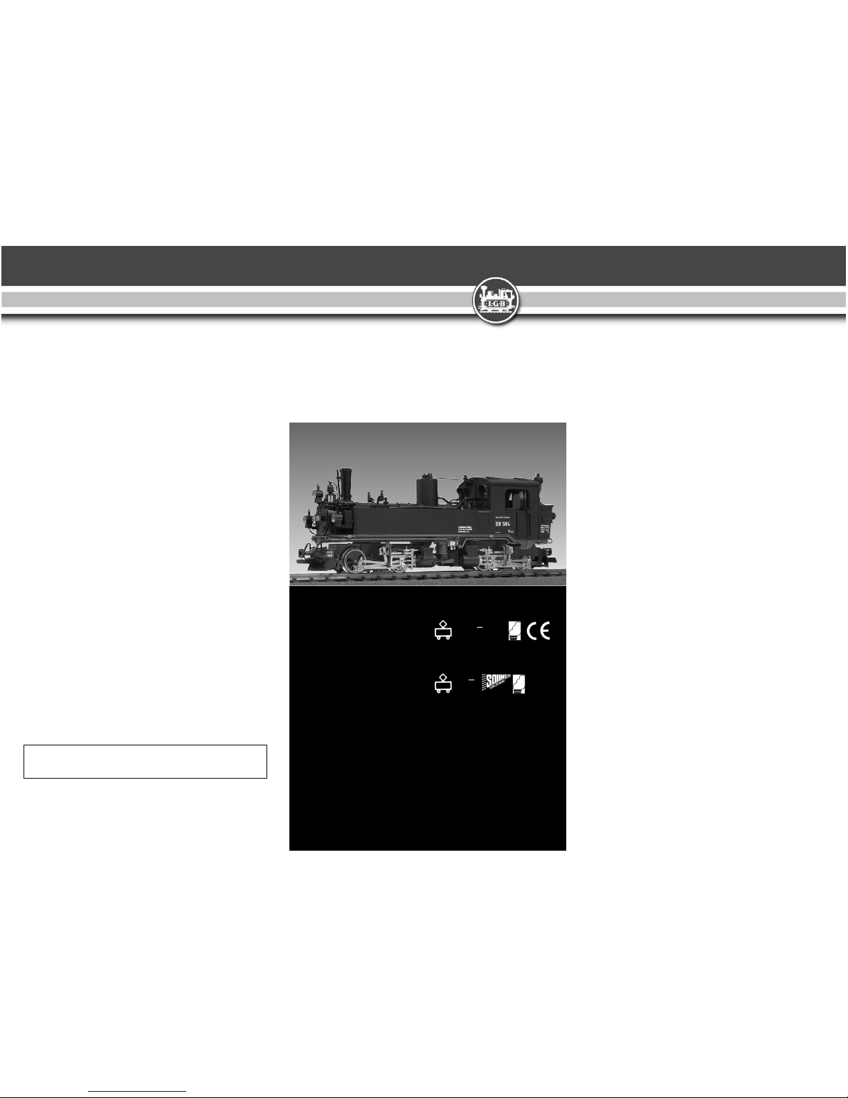
Rü. KB IVK 99594, Sound
Art.Nr. 24842
DC
0-24 V
...
Rü. KB IVK 99594
Art.Nr. 24841
DC
0-24 V
...
DAS VORBILD
Die Königlich Sächsischen Staats eisen bahnen unterhielten ein Schmal spurnetz
mit mehr als 150 km Streckenlänge, um
die gebirgigen Indus trieregionen Sach sens zu erschließen. Nach erfolglosen
Ver suchen mit Lokomotiven der Bauart
Fairlie und Klose wurden ab 1892 insgesamt 96 Meyer- Gelenk loko motiven eingesetzt, die größte Serie dieser ungewöhnlichen Bau art überhaupt. Beide
Trieb werke sind gelenkig gelagert,
wobeider Abdampf des hinteren Hoch -
druck triebwerks die vorderen Zylin der
antreibt. Die Loks bewährten sich und
wurden nach der Einreihung in die Deut sche Reichsbahn auch auf anderen
ostdeut schen Schmalspurstrekken eingesetzt, so beispielsweise auf Rügen. In
den 50er Jahren wurden 22 Loko mo tiven im RAW Görlitz “erneuert”, d. h. sie
erhielten neue geschweißte Kessel, Rah men und Zylinder. Heute verkehren einige der Loks auf Museumsbahnen.
Page 2
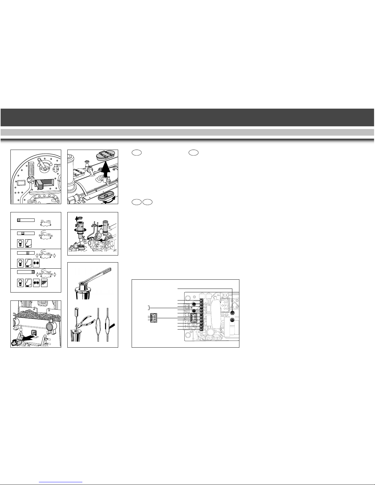
Abb. 1, 2 Betriebsartenschalter
Abb. 3 Mehrzweck-Steckdose
Abb. 4 Lautstärke-Regler
Abb. 5 Sicherheitsabdekkung
für Dampfentwickler
Abb. 6 Austausch des
Dampfentwicklers
Abb. 7 DCC-Schnittstelle
Fig. 1, 2 Operating mode switch
Fig. 3 Multi-purpose socket
Fig. 4 Volume control
Fig. 5 Safety cover for steam
generator
Fig. 6 Replacing the steam generator
Fig. 7 DCC interface
4 373
USA
GB
FD
SND
F2
Licht hinten / rear light
F2
F1
MotorGleis / Track-
Gleis / Track+
Motor+
Licht vorne / front light
Decoder GND
Decoder+
Decoder GND
Decoder+
F1
F2
+6,5V
Sound 65xxx
7
3
0 12 3
012 3
0123
012 3
2
0123
1
Illustr. 1, 2 Sélecteur d'alimentation
Illustr. 3 Douille à usages multiples
Illustr. 4 Commande de réglage du
volume sonore
Illustr. 5 Couvercle de sécurité pour
générateur de fumée
Illustr. 6 Remplacement du
générateur de fumée
Illustr. 7 Interface DCC
5
4
6
Page 3

5
DAS MODELL
Allgemeines
Die DB-Dampflok gehört zum LGBProgramm mit mehr als 600 hoch wer tigen Produkten. Das Programm
umfasst: Fahrzeuge, Gleissystem
und Zubehör in der Baugröße G so wie das LGBMehrzugsystem- MZS.
Weitere Informationen über das kom plette LGB-Programm finden Sie im
großen LGB-Katalog.
Sicherheitshinweis
ACHTUNG! Die Sicherheitshinweise
in dieser Betriebsanleitung sind zu
beachten!
Ausführung
- wetterfestes Modell mit hoher
Detaillierung.
- reichhaltige Ausstattung.
Ausstattung (2x841, 2x842)
- Haftreifen . . . . . . . . . . . . . . . . . .1
- Stromabnehmer12
- Achsen, angetrieben4
- Mehrzwecksteckdose . . . . . . . . .1
- Getriebe gekapselte, mit
siebenpol. Bühler-Motoren
3
. . . .1
- Lampen, Lichtwechsel an/aus in
Fahrtrichtung
3
. . . . . . . . . . . . . . 7
- Dampfentwickler . . . . . . . . . . . . 1
- DCC-Schnittstelle (2x841)......1
- Länge . . . . . . . . . . . . ca. 475 mm
- Gewicht . . . . . . . . . . ca. 3650 g
- Spannungsbegrenzungs- System
(5V)
- Betriebsartenwahlschalter,
vierstufig
- zu öffnen sind:
- Führerstandstüren
- Wasserkastenabdeckung
- Rauchkammertür
Ausstattung (2x842)
- Eingebauter Sound- und MZS Decoder onboard für Analog-und
Digitalbetrieb.
- Fernbedienung der Sound- Funk -
tionen mit MZS
- digitales Dampflokgeräusch
3
- mit MZS ist lastabhängiges
Dampf geräusch möglich
- Glocke und Pfeife
- Bremsgeräusch
- Luftpumpe, Überdruckventil und
Zischen des Dampfes
- Geräusch des Kohleschaufelns
- Lautstärke-Regler
Lieferumfang (Zubehör)
- Figur, Lokführer . . . . . . . . . . . . . 1
- Dampf- und Reinigungs flüssigkeit
2
, . . . . . . . . . . . . .10ml
- Bedienungsanleitung . . . . . . . . . 1
- Sound-Schaltmagnet . . . . . . . . . 2
Vor Inbetriebnahme
ACHTUNG! Bei längerer Benutzung
kann Abrieb durch mechanische Teile
entstehen, der sich in Teppichen und
anderen Materialien festsetzt. Beden ken Sie dies beim Aufbau der Gleise.
Hinweis:
Bei Schäden übernimmt LGB keine
Haftung.
Stromversorgung
ACHTUNG! Um Sicherheit und Zuver lässigkeit zu gewährleisten, darf das
Modell nur mit LGBTrafo (mind. 1 A
Fahrstrom) betrieben werden. Bei Ver wendung von anderen Trafos wird die
Garantie ungültig.
Hinweis:
Weitere Informationen über die LGBTrafos und Fahrtregler zur Verwen dung im Haus oder im Freien und
über das MZSMehrzugsystem finden
Sie im LGB-Katalog.
Betrieb
ACHTUNG! Nicht mehrere Triebfahr zeuge mit unterschiedlichem Anfahr verhalten zusammenkuppeln, da dies
zu Getriebeschäden führen kann.
Page 4

6
Betriebsarten
Das Modell hat einen vierstufigen
Betriebsarten-Schalter im Führer stand (Abb. 1, 2).
Pos. 0: Stromlos abgestellt
Pos. 1: Beleuchtung und Dampf -
entwickler eingeschaltet
Pos. 2: Lokmotoren, Dampfent -
wickler und Beleuchtung
eingeschaltet
Pos. 3: Sound (nur 2x842), Lok -
motoren, Dampfent wickler,
Beleuchtung eingeschaltet
(werkseitige Einstel lung bei
Auslieferung)
Beleuchtung
Die Stirnbeleuchtung ein/aus der Lok
wechselt mit der Fahrtrichtung.
Mehrzweck-Steckdose
Eine Mehrzweck-Steckdose für Flach stecker befindet sich an der Rück wand
(Abb. 3).
Funktion:
Über diese Steckdose können Sie z.B.
LGB-Wagen mit Beleuchtung oder
mit Geräuschelektronik an die Gleis spannung anschließen. Dazu die Ab deckung der Steckdose mit einem
kleinen Schraubenzieher vorsichtig
her aus hebeln.
ACHTUNG! Nicht das äußere rechteckige Gehäuse herausziehen!
Dampfentwickler
Das Heizelement in der Mitte des
Dampf entwicklers nicht berühren, es
ist heiß und zerbrechlich.
Nicht für Kinder, Benutzung nur durch
Erwachsene!
Hinweis:
Den Schornstein nur zur Hälfte mit
der Flüssigkeit füllen. Wenn zu viel
Flüssigkeit verwendet wird, kann
diese nicht verdampfen.
ACHTUNG! Nur LGB-Dampf- und
Reini gungsflüssigkeit
2
verwenden.
An dere Flüssigkeiten können Ihre
Lok beschädigen.
Hinweise auf der Probepackung bzw.
der Flasche beachten. Der Dampf ent wickler kann “trocken” ohne Dampf flüssig keit betrieben werden.
DCC-Schnittstelle
(Abb. 7)
Funktion:
- Ermöglicht das Anschliessen kompatibler Digitaldecoder.
- Es wird empfohlen, den MZS LokDecoders III
2
(LGB 55027) zu verwenden, dessen Stecker direkt auf
die Schnittstelle passt.
Hinweis:
Wir empfehlen, den Decoder in der
LGB-Service-Abteilung einbauen zu
lassen. Weitere Informationen erhalten Sie bei Ihrem LGB-Fachhändler
oder direkt bei LGB (siehe
Autorisierter Se rvi ce).
Hinweis zur Selbstmontage:
- Brücke auf der Decoderschnittstelle
abziehen.
- Decoder auf die Stifte der Platine
aufstecken. Der Stecker am Deco der kabel passt nur in einer Aus rich tung auf die Stifte der Platine.
- Wenn ein Decoder in die Lok eingebaut ist, ist der Betriebsarten schalter funktionslos.
Hinweis zur Demontage:
- Falls der Decoder wieder ausgebaut
wird, muss die Brücke wieder auf
die DCC Schnittstelle aufgesteckt
wer den.
- Die Lok funktioniert sonst nicht.
Analogbetrieb
Hinweis:
Das Modell 23842 mit MZS-Decoder
onboard, kann unverändert auf herkömmlichen analogen Anlagen einge setzt werden, solange diese Funk tion
nicht in den CV-Einstel lungen geändert wurde.
Page 5

Sound im Analogbetrieb
(Modell 2x842)
Hinweis:
Um beim Analogbetrieb die Stand geräusche zu hören, muss eine ge ringe Spannung (ca. 6,5 Volt) an den
Gleisen anliegen. Drehen Sie dazu
den Regler auf eine Fahrstufe, in der
die Lok noch nicht anfährt, die Ge räusche jedoch bereits zu hören sind.
Um beim Analogbetrieb, bei Trafo stel lung = 0 und bei Fahrtrichtungs wechseln die Standgeräusche zu
erhalten, muss die StandgeräuschStrom versorgung2eingebaut werden.
Bei Fragen zum Einbau wenden Sie
sich bitte an Ihren Fachhändler.
Glocke und Pfeife:
- Glocke und Pfeife können durch
den Sound-Schaltmagneten2ausgelöst werden.
- Der Sound-Schaltmagnet2lässt
sich zwischen die Schwellen der
meisten LGB-Gleise klipsen.
- Ist der Sound-Schaltmagnet2in
Fahrtrichtung auf der linken Seite
angebracht, wird die Glocke aus ge löst.
- Auf der rechten Seite wird die Pfeife
ausgelöst.
Elektronischer Sound
(Modell 2x842)
Sound im Digitalbetrieb
Die digitale Geräuschelektronik dieser
Lokomotive gibt vorbildsnah den
Sound der Vorbildlok wieder. Der
Lau tstärke- Regler befindet sich
unter der Abdeckung des Wasser kastens (Abb. 4).
Das Dampfgeräusch ist mit der Rad umdrehung synchronisiert. Der Takt
des Abdampfgeräusches ist werkseitig auf 2 Auspuffschläge pro Rad umdreh ung eingestellt. Dies kann
vorbildgetreu auf 4 Auspuff schläge
pro Radumdrehung geändert werden, indem Bit 7 in CV54 auf "64"
programmiert wird
4
. Zusätzlich zum
Abdampfgeräusch ist das Zylinder -
neben geräusch zu hören.
Hinweis:
Alle nachfolgend beschriebenen
Sound- Funktionen lassen sich auch
direkt über das LGBMehrzugsystemMZS auslösen.
Glocke und Pfeife:
- Beim Anfahren der Lok ertönt die
Pfeife.
- Glocke und Pfeife können auch
durch den EPL-Gleiskontakt
2
mit
dem LGB-Sound-Schaltmagneten
2
ausgelöst werden.
Hinweis:
Siehe auch Sound im Analogbetrieb.
Bremse:
- Wird die Lok langsam abgebremst,
ertönt das Geräusch der “kreischenden” Bremsen.
Hinweis:
Für das Auslösen des Geräusches
be nötigt man etwas Übung mit dem
Handregler.
Standgeräusch:
- Beim Betrieb mit dem Mehrzug system-MZS hört man im Stand
das Rauschen des Dampfes im
Kessel, sowie abwechselnd Luftund Wasserpumpe.
Elektronischer Sound
(Nachrüsten bei Modell 2x841)
Um dieses Modell mit Sound auszustatten, empfehlen wir folgende
Artikel:
- LGB 65000 Europäisches Dampf
Sound-Modul
- LGB 65011 Standgeräusch-Strom versorgung (nicht nötig bei Betrieb
mit MZSMehrzugsystem)
Tipp:
Falls in der Lok nicht genug Platz ist
oder Sie die Lok nicht demontieren
wollen, kann das Modul auch in
einen Wagen platziert und über die
Mehrzwecksteckdose an die Lok an ge schlossen werden.
7
Page 6

8
LGB-Mehrzugsystem-MZS
Das Modell 2x842 mit werkseitigem
MZS-Decoder onboard, kann un ver än dert auf digitalen Anlagen eingesetzt werden.
Bei digitalem Betrieb verfügt die Lok
über eine Lastnachregelung: Das
heißt, die Motordrehzahl (und damit
unter normalen Bedingungen die Ge schwindigkeit) wird konstant gehalten, auch wenn sich die Belas tung der
Lok ändert, z. B. in Kurven oder auf
Steigungen.
Hinweis:
Die Lastnachregelung funktioniert
nicht bei bereits maximaler Be las tung/Geschwindigkeit, da dann keine
Spannungsreserve zur Verfügung
steht.
Werkseitige Einstellungen
Hinweis:
Diese sind der CV-Liste zu entnehmen.
Ferngesteuerte Funktionen
Hinweis:
Für diese werden LGB-Handys be nötigt.
Funktion:
Durch das Drücken der ent sprechen den Taste werden untenstehende
Funk tionen ausgelöst.
Funktionstasten:
1 Pfeife
2 Bremsgeräusch
3 Glocke
4 Ansage: "Verehrte Fahrgäste: Bitte
einsteigen und Türen schließen.
Vorsicht bei der Abfahrt des
Zuges!"
5 Wasserstrahlpumpe
6 Generator
7 Dampfentwickler aus/ein
8 Geräuschelektronik aus/ein
Beleuchtungstaste:
9 Beleuchtung aus/ein
Datenübertragung (seriell)
Bei älteren MZS-Komponenten wer-
den die Befehle als Aneinander reihung von einzelnen Befehlen ge sendet (z.B. 3 = 1+1+1). Die meisten
MZS-Komponenten lassen sich aber
durch ein Upgrade auf parallele
Funk tions auslösung umstellen.
Ausnahmen:
- MZS-Zentrale der 1. Generation
55000 und
- Lokmaus 55010.
Hinweis:
Weitere Informationen erhalten Sie
bei Ihrem Fachhändler.
Datenübertragung (parallel)
Bei den mit "P" gekennzeichneten
MZSKomponenten werden die Funk tionen dieser Lok parallel ausgelöst,
d.h., es entfällt die Pause, die beim
"seriellen" Auslösen entsteht.
Programmierung
Es können zahlreiche Funktionen des
Decoders onboard programmiert
wer den, z.B.:
- Beschleunigung
- Bremsverhalten
- Fahrtrichtung
- und vieles mehr
4
Die Programmierung kann sowohl
über das MZS-PCDecoderprogram m ier modul 55045 als auch über das
MZSUniversal- Handy 55015 erfolgen4.
WARTUNG
Schwierigkeitsgrade der Wartungs arbeiten:
- Einfach
- Mittel
- Fortgeschritten
ACHTUNG! Bei unsachgemäßer War tung erlischt der Garantie anspruch.
Hinweis:
Um fachgerechte Reparatur leis tung en
zu erhalten, wenden Sie sich an Ihren
Fachhändler oder an die LGB ServiceAbteilung (siehe Autorisier ter Service).
Page 7

9
Schmierung
- Die Achslager und die Lager des
Gestänges hin und wieder mit je
einem Tropfen LGBPflegeöl ölen.
Reinigung
- Sie können das Gehäuse Ihres Mo dells mit einem milden Reini gungs mittel reinigen.
ACHTUNG! Das Modell nicht in das
Reinigungsmittel eintauchen.
ACHTUNG! Ist das Modell mit einem
Laut sprecher ausgestattet, darf dieser
nicht direkt mit Wasser in Be rühr ung
kommen.
Austauschen der Glühlampen :
- Vorsichtig das Glas von der
Laterne hebeln.
- Mit einer Pinzette die eingesteckte
Glühlampe aus der Fassung ziehen.
- Neue Glühlampe einsetzen.
- Modell wieder zusammenbauen.
Innenbeleuchtung :
- Glühlampe mit einer Pinzette aus
der Fassung ziehen.
- Neue Glühlampe einstecken.
Austausch des
Dampfentwicklers
- Abdeckung aus dem Schornstein
ziehen (Abb. 5).
- Beschädigten Dampfentwickler
(Schornsteineinsatz) mit einer
Spitzzange oder einer Pinzette aus
dem Schornstein ziehen.
- Kabel durchtrennen.
- Kabel mit dem neuen Dampfent wickler verbinden. Dabei die abisolierten Kabelenden verdrehen und
isolieren (Abb. 6).
- Neuen Dampfentwickler in den
Schornstein schieben.
- Modell wieder zusammenbauen.
Austauschen des Haftreifens
- Schraube vor dem hinteren Ge triebe lösen.
- Schraube an der hinteren Kupp lung entfernen.
- Die beiden Sechskantschrauben an
den hinteren Treibrädern entfernen
und die Treibstangen lösen.
- Hinteres Getriebe aus der Lok
ziehen.
- Mit einem kleinen flachen Schrau ben dreher den alten Haftreifen
entfernen:
- Den alten Haftreifen aus der Rille
(Nut) im Treibrad hebeln.
- Vorsichtig den neuen Haftreifen
2
über das Rad schieben und in die
Rille (Nut) im Treibrad einsetzen.
- Überprüfen, ob der Haftreifen richtig sitzt.
- Modell wieder zusammenbauen.
Ersatzteile
1
50010 Dampf- und Reinigungsöl
50019 Pflegeöl
51020 Getriebefett
62201 Universalmotor mit kurzer
Welle
63120 Stromabnehmerkohlen mit
Hülsen, 8 Stück (2 Pack ung en nötig)
63218 Schleifkontakte, 2 Stück
(2 Packungen nötig)
65853 Schornsteineinsatz, 5V
68511 Steckglühlampe klar, 5V,
10 Stück
69104 Haftreifen 37,5 mm,
10 Stück
Zubehör
2
17010 Schaltmagnet
17050 Sound-Schaltmagnet
17100 EPL-Gleiskontakt
55027 MZS-Decoder III (2x841)
65011 Standgeräusch- Strom ver -
sor gung
68513 Steckglühlampe klar, 24V
Index
1
= Ersatzteil
2
= Zubehör
3
= abschaltbar
4
= siehe Anleitung für
Fortgeschrit tene
Page 8

10
ANLEITUNG FÜR
FORTGESCHRITTENE
MZS-Decoder onboard
Um die Funk tionen des MZSDecoder
onboard individuell zu ändern, können die Funk tionsvariablen (Configu ration Variables - CVs) in den Regis tern pro gram miert werden.
Dazu wird benötigt:
- Das MZS-PCDecoderprogrammier modul 55045 oder
- Universal-Handy 55015
Hinweis:
Für normalen Betrieb ist es nicht notwendig, die Funktionswerte zu ändern.
Programmierung
Hinweis:
Beachten Sie die Betriebsanlei tungen:
- MZS-PCDecoderprogrammier modul 55045 bzw.
- Universal-Handy 55015.
Auslieferungszustand
- Bei Fehlprogrammierungen kann
der Auslieferungszustand der wichtigsten Register des MZS-Decoders
onboard wieder hergestellt werden!
- Hierzu den Funktionswert 55 in
Register CV 55 eingeben.
Dabei wird auch die Lokadresse
wieder auf den werkseitigen Wert
= 3 programmiert.
Page 9

11
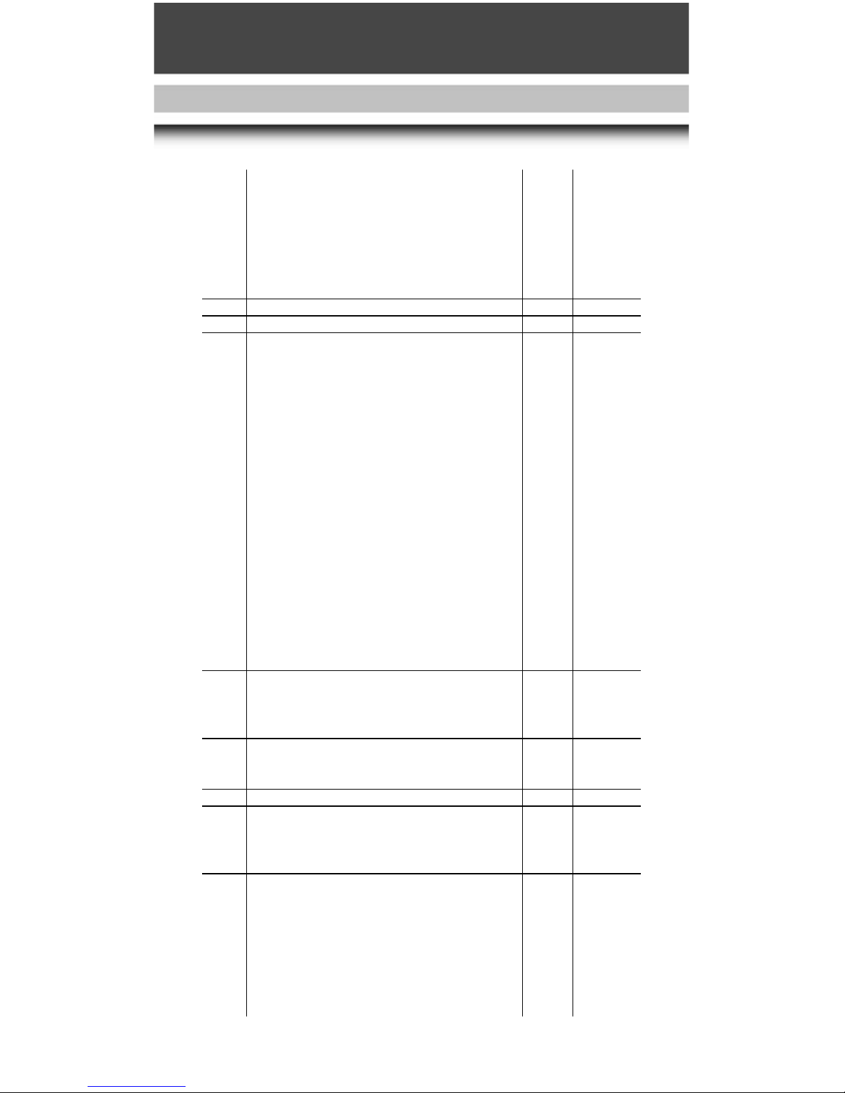
Folgende CVs können programmiert werden:
Register Belegung Bereich Werkseitige
Einstellung
CV1 Lokadresse (00-22) [3]
Mit LGB-Mehrzugsystem
CV2 Anfahrspannung (0-255) [2]
Spannungswert bei Fahrstufe 1 - falls Lok erst in höherer
Fahrstufe anfährt, Wert erhöhen.
CV3 Beschleunigung (1-255) [3]
1 = schnelle Beschleunigung, 255 = langsame B.
CV4 Verzögerung (1-255) [3]
1 = schnelles Bremsen, 255 = langsames Bremsen
CV5 Maximale Fahrspannung (1-255) [255]
Spannungswert für höchste Fahrstufe - wenn gerin-gere
Höchstgeschwindigkeit gewünscht wird, Wert verringern.
CV5 nach Eingabe von CV6 (beim Programmieren mit älteren
55015) Funktionswert im zu programmierenden Register
CV6 CV-Nr. des zu programmierendes Register
(beim Programmieren mit älteren 55015)
CV29 NMRA-Konfiguration [4]
Bit-Programmierung
Bit 1: Fahrtrichtung, 0 = normal, 1 = invers [0]
Bit 2: Fahrstufen, 0 = 14 (LGB), 2 = 28 [0]
Bit 3: Analogbetrieb, 0 = gesperrt, 4 = möglich [4]
Bit 4: nicht besetzt [0]
Bit 5: Fahrstufentabelle, 0 = werkseitig programmiert,
16 = vom Anwender programmiert [0]
Bit 6: Adressbereich, 0 = 0-127 (LGB), 32 = 128-10039 [0]
Zum Programmieren die Werte für die einzelnen Bits
addieren und das Ergebnis als Funktionswert
programmieren.
Hinweis: Um eine Lok auf inverse Fahrtrichtung zu
programmieren (z. B. F7 A-B-A-Kombination), Funktionswert 5 programmieren.
Achtung! Lokadressen 128-10039 und 28 Fahr-stufen
sind nicht mit dem LGB-MZS verwendbar.
CV49 Spannungswert für Funktionsausgang F1 (1-32) [32]
(Lokspezifisch, nicht verändern, da sonst Funktionen
beeinträchtigt oder zerstört werden können)
CV50 Spannungswert für Lichtausgänge (siehe CV49) (1-32) [5]
CV51 Schalttaste für Funktionsausgang F1 [13]
0 = Lichttaste 9
1 = Taste 1 (Tasten 2-8 nicht belegt)
9 = Taste 1 (Tasten 2-8 ebenfalls belegt)
10 = Taste 2
11 = Taste 3
12 = Taste 4
13 = Taste 5
14 = Taste 6
Page 10
12
15 = Taste 7
16 = Taste 8
64 = Lichttaste 9 (ein nur bei Rückwärtsfahrt)
65 = Taste 1 (ein nur bei Rückwärtsfahrt)
128 = Lichttaste 9 (ein nur bei Vorwärtsfahrt)
129 = Taste 1 (ein nur bei Vorwärtsfahrt)
(Lokspezifisch, nicht verändern, da sonst Funktionen
beeinträchtigt oder zerstört werden können)
CV52 Schalttaste Licht vorne (siehe CV51) [128]
CV53 Schalttaste Licht hinten (siehe CV51) [64]
CV54 LGB-Konfiguration [2] [2]
Bit-Programmierung
Bit 1: Übernahme-Funktion, 0 = aus, 1 = ein [0]
Bit 2: Lastnachregelung mit MZS, 0 = aus, 2 = ein [2]
Bit 3: Lastnachregelung ananlog, 0 = aus, 4 = ein [0]
Bit 4: ohne Funktion
Bit 5: 0 = F1 konstant, 16 = F1 blinkend [0]
Bit 6: 0 = F2 konstant, 32 = F2 blinkend [0]
Bit 7: 0 = Zwei Auspuffschläge/Radumdrehung,
64 = Vier Auspuffschläge [0]
Bit 8: Automatisches Bremsgeräusch, 0 = ein,
128 = aus [0]
Zum Programmieren die Werte für die einzelnen Bits
addieren und das Ergebnis als Funktionswert programmieren. Die Werte für Bit 5-8 variieren von Lok zu Lok.
Die Werte für Ihre Lok können über das MZS-PC-De coderprogrammiermodul 55045 ausgelesen werden.
Übernahme-Funktion ein: Beim Betrieb mit 55015 kann
nach Anwählen der Lok die Reglerstellung 2 Sekunden
lang nachgeregelt werden, ohne dass die Lok anhält
CV55 Wiederherstellen des Auslieferungszustands
Programmierung:
6-55->
5-55->
CV56 Spannungswert für Funktionsausgang F2 (1-32) [5]
(Lokspezifisch, nicht verändern, da sonst Funktionen
beeinträchtigt oder zerstört werden können)
CV57 Schalttaste für Funktionsausgang F2 (siehe CV51) [15]
CV58 Pausen-Pendelzeit (Analogbetrieb) (0,5 Sekunden x Wert) (0-255) [0]
(0-255) [0] Wenn die analoge Fahrspannung umgepolt
wird, wartet die Lok entsprechend der eingestellten Zeit,
bevor sie in der neuen Fahrtrichtung anfährt
CV60 Lastnachregelung: Maximaler Nachregelfaktor (1-255) [4]
Legt maximale Erhöhung oder Verringerung des
Spannungswerts fest, der pro Zeiteinheit (aus CV61)
nachgeregelt wird.
1 = kleine Nachregelungsschritte,
255 = große Nachregelungsschritte
Werkseitige Programmierung ist optimal an LGB- Motoren
angepasst.
Page 11

13
CV61 Lastnachregelung: Nachregelgeschwindigkeit (0-255) [16]
Legt fest, wie oft pro Sekunde nachgeregelt wird - ob die
Lok auf Kurven und Steigungen sofort oder träge reagiert
0 = schnelle Nachregelung, 255 = sehr langsame
Nachregelung
CV62 Lastnachregelung: Nachregelstärke (0-255) [255]
Begrenzt die Nachregelung auf eine maximale
Abweichung vom Sollwert. Bei besonders großen
Belastungen des Motors wird nur bis zu diesem Differenz-
wert nachgeregelt - für realistischeren Betrieb, damit Loks
z. B. bei Bergfahrt nicht voll nachregeln.
0 = keine Nachregelung, 255 = maximale Nachregelung
CV67 Fahrstufentabelle vom Anwender programmiert (0-255)
bis (siehe CV 29) Die Geschwindigkeitstabelle wird immer mit
CV94 28 Werten abgelegt, die in CV 67 bis CV 94 programmiert
werden.
Beim Betrieb mit dem LGB-MZS wird jeder zweite Wert
übersprungen (14 Fahrstufen).
Werkseitig programmierte Fahrstufentabelle:
7, 9, 11, 13, 16, 20, 24, 28, 32, 36, 42, 48, 54, 60, 68, 76,
84, 92, 102, 112, 124, 136, 152, 168, 188, 208, 230, 255
Vorgeladene Werte der programmierbaren Kurve:
8, 16, 24, 32, 40, 48, 56, 64, 72, 80, 88, 96, 104, 112,
120, 128, 136, 144, 152, 160, 168, 176, 184, 192, 208,
224, 240, 255
Hinweis:
Fahrstufentabelle ist werkseitig programmiert und
braucht nicht verändert zu werden.
Zum Programmieren ist das MZS-PC-Decoderprogram-
miermodul 55045 empfehlenswert.
Beispiel zur Bit-Programmierung:
CV 29: Die Lok soll mit inverser Fahrtrichtung mit vom
Anwender programmierter Fahrstufentabelle fahren,
Analogbetrieb soll möglich sein:
Bit 1 = 1, Bit 2 = 0, Bit 3 = 4, Bit 4 = 0, Bit 5 = 16,
Bit 6 = 0. 1+4+16=21.
Also CV 29 auf Funktionswert 21 programmieren.
Page 12

14
Programmieren mit Handy 55015
Vorgehensweise:
- Programmiermodus wählen
- Eingabe > “P”
- Anzeige = “P --”
- Eingabe > 6 - 5 - 5 und rechte
Pfeiltaste
- Anzeige = “P --”
- Eingabe > 5 - 5 - 5 und rechte
Pfeiltaste
Hinweis:
Auslieferungszustand ist wieder hergestellt.
AUTORISIERTER SERVICE
Bei unsachgemäßer Wartung wird
Ihre Garantie ungültig. Um fachgerechte Reparaturleistungen zu erhalten, wenden Sie sich an Ihren
Fachhändler oder an die LGBService-Abteilung:
Gebr. Märklin & Cie. GmbH
LGB Service-Abteilung
Witschelstraße 104
90431 Nürnberg
Deutschland
Telefon: (0911) 83707-38
Telefax: (0911) 83707 818
Die Einsendung erfolgt zu Ihren
Lasten.
VORSICHT! Dieses Modell ist nicht
für Kinder unter 8 Jahren geeignet.
Das Modell hat kleine, scharfe und
bewegliche Teile. Verpackung und
Bedienungs anleitung aufbewahren.
Artikel, technische Daten und Liefer daten können sich ohne Vor ankündigung ändern. Einige Artikel
sind nicht überall und über alle
Fachhändler erhältlich. Einige
Abbildungen zeigen Handmuster.
LGB und Märklin sind eingetragene
Marken der Firma Gebr. Märklin &
Cie. GmbH, Göppingen. Andere
Marken sind ebenfalls geschützt.
© Gebr. Märklin & Cie. GmbH
Page 13

15
24841
DB Steam Loco 099 712-2
24842
DB Steam Loco 099 712- 2,
sound
THE PROTOTYPE
The Königlich Sächsischen Staats eisen bahnen (Royal Saxonian State
Railways) operated more than 150
km (94 miles) of narrow-gauge
tracks to reach the mountainous
industrial regions of Saxonia in central Germany. First attempts with
Fairlie and Klose locomotives failed,
but the articulated Meyer locomotives were a great success. Starting
in 1892, 96 of these unusual locomotives were purchased, making
them the largest class of Meyer locomotives ever built. Both drivetrains
are articulated, with the exhaust
steam of the rear high pressure
cylin ders powering the front drivetrain. After the Saxonian railways
were incorporated into the Deutsche
Reichsbahn, the locomotives were
used on other narrow gauge lines,
too, for example, on the Baltic island
of Rügen. In the 1950s, 22 of the
loco motives were rebuilt extensively
at the Görlitz shops, where they
received new welded boilers, frames
and cylinders. Today, some of these
unusual locomotives operate on
museum railways.
THE MODEL
General
This DB steam loco is part of the LGB
range of more than 600 high-quality
products. The product range inclu des: locomotives, trains, track sys-
tem and accessories in size G as well
as the LGB multi-train system MTS.
For more information on the complete LGB product range, please refer
to the comprehensive LGB catalog.
Safety note
ATTENTION! All safety notes given in
these operating instructions must be
observed!
Design
- Weatherproof model as detailed
replica
- Luxuriously equipped
Equipped with (2x841, 2x842)
- Traction tires ...............................1
- Power pickups ..........................12
- Powered wheels..........................8
- Multi-purpose socket ..................1
- Encapsulated gearbox with
seven-pole Bühler engines3........ 2
- Lamps, directional light change
on/off in direction of travel3.........7
- Drivetrain illumination
- Steam generator..........................1
- DDC interface (2x841) ................1
- Length...........ca. 475 mm (21.7in)
- Weight................ca. 3650 g (11lb)
- Voltage limitation system (5V)
- Operating mode selector, four-way
- The following vehicle parts can be
opened:
- cab doors
- Water box cover
- smokebox door
Features (2x842)
- Factory-installed onboard sound
and MTS decoder for analog and
digital operation
- Remote control of sound features
(with Multi- Train System)
- Digital steam engine sound
3
GB
USA
Page 14

- MTS features a load-dependent
steam engine sound
- Bell and whistle
- Brake sound
- Air pump, safety valve and steam
sounds
- Coal shoveling sound
- Volume control
Scope of delivery (accessories)
- Puppet, engine driver..................1
- Steaming and cleaning
fluid2, .....................................10ml
- Operating instructions.................1
- Sound trigger magnet .................2
Prior to start-up
ATTENTION! During extended operation, this model may leave carbon
dust or other debris around the track.
This dust and debris can stain carpet
and other materials. Consider this
when setting up the track.
Note:
LGB are not liable for any damages.
Power supply
ATTENTION! For safety and reliability,
operate this model with LGB transformers only (min. driving current 1
A). The use of non- LGB transformers will void your warranty.
Note:
For more information on LGB transformers, power packs and controls
for indoor, outdoor and multi-train
operation, see the LGB catalog.
Operation
ATTENTION! Do not connect this
model to other loco models with different starting characteristics. This
can damage the internal gearing.
Operating modes
This model has a four-way operating
mode selector mounted inside the
cab (Fig. 1, 2):
Pos. 0: All power off
Pos. 1: Power to lights and steam
generator
Pos. 2: Power to motors, lights and
steam generator
Pos. 3: Power to sound (only
23842), motors, steam generator, lights (factory preset)
Lighting
The head light of the loco (on/off)
changes according to its direction of
travel.
Multi-purpose socket
The model has a multi-purpose socket, suitable for flat connectors, on the
rear wall (Fig. 3).
Function:
This socket can be used to provide
track power to LGB coaches with
lighting or sound electronics.
For this purpose, gently remove the
cover of the socket using a small
strai ght screwdriver to pry it out.
ATTENTION! Do not pull out the rectangular outer housing.
Steam generator
Never touch the heating element
in the center of the steam generator.
It is hot and breaks easily.
Only for use by adults!
Note:
For best operation, fill the generator
only halfway with fluid. If the generator is overfilled, it will not convert the
fluid into steam.
ATTENTION! Only use LGB Steaming
and Cleaning Fluid2. Other fluids
may damage your locomotive. Plea se ob serve the instructions on the
sample or bottle.
The steam generator can be run "dry"
without steaming fluid.
DCC interface
(Fig. 7)
Function:
- This enables the connection of
compatible digital decoders.
16
Page 15

17
- We recommend to use MTS Loco
Decoder III2(LGB 55027) whose
plug directly fits into the socket
interface.
Note:
We recommend to have the decoder
mounted by the LGB factory service
station. For further information,
please contact your authorized LGB
re tailer or (see Authorized Service).
Notes for do-it-yourself assembly:
- Pull off the bridge from the decoder
interface.
- Plug the decoder onto the pins of
the PCB. The plug of the decoder
cable only fits the PCB pins when
aligned correctly.
- When a decoder is integrated in
the locomotive, the power control
switch (mode switch) is obsolete.
Notes for disassembly:
- If you wish to remove the decoder,
the bridge must be remounted onto
the DCC interface.
- Otherwise, the loco does not work.
Analog mode
Note:
Model 23842 with MTS Onboard De coder can also be operated on traditional analog systems without making any alterations, provided that this
function has not been changed in the
CV settings.
Sound in analog mode
(Model 2x842)
Note:
To hear the standing sounds in analog mode, a low voltage (approx. 6.5
volts) must be maintained on the
tracks. Turn the throttle to a low setting so that the loco does not yet
start, but you can hear the sounds.
To obtain standing sounds in analog
operating mode, while the throttle is
turned off, and when reversing the
locomotive's direction, the Standing
Sounds Power Supply Unit2 must be
installed. For questions regarding the
installation, please contact your au tho rized retailer.
Bell and whistle:
- The bell and whistle can be triggered using the Sound Trigger
Magnet.
2
- The Sound Trigger Magnet2snaps
between the ties of most LGB track
sections.
- When the Sound Trigger Magnet
2
is fitted on the left in direction of
travel, the bell will be rung.
- If fitted on the right, the whistle
will be blown.
Electronic sound
(Model 2x842)
Sound in digital mode
The digital electronic sound system
imitates the sound of the original
steam locomotive. The volume control is fitted underneath the water
box cover (Fig. 4).
The steam sounds are synchronized
with the wheel revolutions. The sou nd is factory- set to 2 chuffs per revolution. If you prefer the typical 4
chu ffs per revolution, reprogram bit
7 in CV54 to "64"4.
In addition to the steam chuffs, you
hear the sounds of the cylinders.
Note:
All sound features described below
also can be controlled directly with
the LGB Multi-Train System.
Bell and whistle:
- The whistle is blown, when the
locomotive is started.
- Bell and whistle can also be operated by the LGB Sound Trigger
Magnet
2
using the EPL Track
Contact2.
Note:
Also see sound in analog mode.
Page 16

Brake:
- When the loco speed is reduced
slowly, a "squealing" brake sound is
produced.
Note:
This requires a little practice with the
manual speed control.
Standing sounds:
- With the Multi-Train System, you
hear the boiler sounds while the
loco is standing, as well as alternating air and water pump noise.
Electronic sound
(Retrofitting for Model 2x841)
To equip this model with sound features, we recommend the following
products:
- LGB 65000 European Steam Sound
Module
- LGB 65011 Standing Sound Power
Supply Unit (not required, when
operating an MTS Multi-Train
System)
Tip:
If the loco doesn't provide enough
space, of if you do not wish to disassemble it, the module may also be
placed in a coach. It can be connected to the loco using the multi-purpose socket.
LGB Multi-Train System MTS
Model 2x842 with factory- installed
MTS Onboard Decoder can be operated on digital systems without any
alterations.
In digital mode, the loco has a load
readjustment function, which means
that the motor speed is kept constant
(and under normal conditions the
loco speed), even when the load of
the loco changes, for example, in
cur ves or on grades.
Note:
This feature does not work at maximum load/speed, because in that
case there would be no voltage
reserve.
Factory settings
Note:
Please refer to the CV list.
Remote-controlled functions
Note:
LGB remote control units are requi red for the following functions.
Function:
Pressing the appropriate key triggers
the functions listed below.
Function keys:
1 Whistle
2 Brake sound
3 Bell
4 Conductor announcement: "Dear
passengers: All aboard and close
the doors please! Be careful as the
train leaves."
5 Water jet blast
6 Generator
7 Steam generator off/on
8 Sound electronics off/on
Lighting key:
9 Lighting off/on
Data transmission (serial)
With older MTS components, commands are transmitted as a sequence
of single commands (e.g. 3 =
1+1+1).
However, most MTS components
can be upgraded to parallel function
commands.
Exceptions:
- First generation 55000 MTS Central
Station and
- 55010 Train Mouse.
Note:
For more information, contact your
authorized retailer.
Data transmission (parallel)
When using MTS components
marked with a "P", the loco can re ceive "parallel" function commands,
which eliminate the pause that occurs
when a "serial" command is received.
18
Page 17

19
Programming
Numerous functions of the onboard
decoders can be configured, e.g.
- Acceleration
- braking response
- direction of travel
- and many more.
4
The decoder can either be configured
using the 55045 MTS- PC Pro gram ming Module or the 55015 MTS Uni versal Remote Control Unit.
4
SERVICE
Do-it-yourself service levels
- Beginner
- Intermediate
- Advanced
ATTENTION! Improper service will
void your warranty.
Note:
For quality service, contact your au thorized retailer or an LGB factory
ser vice station (see Authorized
Service).
Lubrication
- The axle bearings and the side rod
bearings should be lubricated
occasionally with a small amount
of LGB Maintenance Oil.
Cleaning
- This model can be cleaned externally using a mild detergent and
gentle stream of water.
ATTENTION! Do not immerse this
model in the detergent.
ATTENTION! If the model is equipped
with a loudspeaker, it must not be ex posed to water directly.
Replacing the light bulbs :
- Carefully pry the lens away from
the lantern.
- Using tweezers, remove the bulb.
- Plug in new bulb.
- Reassemble.
Interior lighting :
- Using tweezers, remove the bulb.
- Plug in new bulb.
Replacing the steam generator
- Pull the safety cover out of the
smoke stack (Fig. 5).
- Use pliers or tweezers to pull the
old steam generator out of the
stack.
- Cut the wires.
- Connect the wires to the new generator. Twist the stripped wire ends
and insulate them (Fig. 6).
- Push the new generator into the
stack.
- Reassemble.
Replacing the traction tire
- Loosen the screw in front of the
rear gearbox.
- Remove the screw at the rear coupling.
- Remove the two hex head screws
from the rear drive wheels and lift
off the driving rods.
- Pull off the rear gearbox from the
loco.
- Use a small, straight screwdriver
to replace the old traction tire:
- Pry the old traction tire out of the
wheel groove.
- Gently push the new traction tire
2
over the wheel and into the groove
of the traction wheel.
- Make sure that the traction tire is
seated properly in the wheel
groove.
- Reassemble.
Page 18

20
Spare parts
50010 Steaming and Cleaning Fluid
50019 Maintenance Oil
51020 Gear Lubricant
62201 Universal Motor with short
shaft
63120 Brushes with bushings,
8 pieces
(2 packages needed)
63218 Standard Pick-Up Shoes,
2 pieces
(2 packages needed)
65853 Stack, 5V
68511 Plug-In Bulb, Clear, 5V,
10 pieces
69104 Traction Tire 37.5 mm,
10 pieces
Accessories
2
17010 EPL Loco Magnet
17050 Sound Trigger Magnet
17100 EPL Track Contact
55027 MTS Onboard Decoder III
(23841)
65011 Standing Sounds Power
Supply Unit
68513 Plug-In Bulb, Clear, 24V
Index
1
= Spare part
2
= Accessories
3
= Switch-off option
4
= See Instructions for
Advanced Users
INSTRUCTIONS FOR ADVANCED
USERS
MTS Onboard Decoder
To change the functions of the MTS
Onboard Decoder as desired, configuration variables (CVs) can be programmed in the registers.
This option requires the following
equip ment:
- 55045 MTS PC Decoder
Programming Module or
- 55015 Universal Remote Control
Unit
Note:
For normal operation, it is not necessary to change any function values.
Programming
Note:
Please consult the operating instructions for the
- 55045 MTS PC Decoder Program ming Module or
- 55015 Universal Remote Control
Unit
Original factory settings
- If programming results in unsatisfactory operation, the original factory settings of the MTS Onboard
Decoder can be recovered for the
most important registers!
- To do this, enter function value 55
in register CV 55.
This also reprograms the loco
address to the factory-set value = 3.
Page 19

21
The following registers can be configured:
Register Function Available Factory
values setting
CV1 Loco address
With LGB Multi-Train System (00-22) [3]
CV2 Starting voltage (0-255) [2]
Voltage for speed setting 1 - if loco only starts at a
higher speed setting, increase value.
CV3 Acceleration (1-255) [3]
Acceleration (1 = fast, 255 = slow)
CV4 Braking (1-255) [3]
1 = fast, 255 = slow
CV5 Maximum track voltage (1-255) [255]
Voltage for highest speed step - if a lower top speed is
desired, decrease value.
CV5 Function value for CV to be programmed after input of
CV6 (when programming with older 55015)
CV6 CV to be programmed
(when programming with older 55015)
CV29 NMRA configuration [4]
Bit configuration
Bit 1: direction of travel, 0 = normal, 1 = reversed [0]
Bit 2: speed steps, 0 = 14 (LGB), 2 = 28 [0]
Bit 3: analog operation, 0 = not possible, 4 = possible [4]
Bit 4: not assigned [0]
Bit 5: speed steps table, 0 = factory-programmed,
16 = user-programmed [0]
Bit 6: address area, 0 = 0-127 (LGB), 32 = 128-10039 [0]
To program, add the values for the individual bits and
program the resulting function value.
Note: To program a loco to reversed direction of travel
(e.g. F7 A-B-A combination), program function value 5.
Attention! Loco addresses 128-10039 and 28 speed
steps cannot be used with LGB MTS.
CV49 Voltage for function terminal F1 (1-32) [32]
(depends on loco model, do not change, as functions can
be affected or destroyed)
CV50 Voltage for lighting terminals (see CV49) (1-32) [5]
CV51 Command key for function terminal F1 [13]
0 = lighting button 9
1 = button 1 (buttons 2-8 not assigned)
9 = button 1 (buttons 2-8 also assigned)
10 = button 2
11 = button 3
12 = button 4
13 = button 5
14 = button 6
15 = button 7
16 = button 8
Page 20

64 = lighting button 9 (ON only when loco is reversing)
65 = button 1 (ON only when loco is reversing)
128 = lighting button 9 (ON only when loco is moving forward)
129 = button 1 (ON only when loco is moving forward)
(Depends on loco model, do not change, as functions
can be affected or destroyed)
CV52 Command key for front lighting terminal (see CV51) [128]
CV53 Command key for rear lighting terminal (see CV51) [64]
CV54 LGB configuration [2] [2]
Bit configuration
Bit 1: hand-off function, 0 = off, 1 = on [0]
Bit 2: MTS Back-EMF, 0 = off, 2 = on [2]
Bit 3: analog Back-EMF, 0 = off, 4 = on [0]
Bit 4: no function
Bit 5: 0 = F1 constant, 16 = F1 flashing [0]
Bit 6: 0 = F2 constant, 32 = F2 flashing [0]
Bit 7: 0 = two chuffs/revolution,
64 = four chuffs [0]
Bit 8: automatic brake sounds, 0 = on, 128 = off [0]
To program, add the values for the individual bits and
program the resulting function value.
The values for Bits 5-8 vary between locos. The values for
your loco can be read using the 55045 MTS PC Decoder
Programming Module.
Hand-off function ON: When operating with 55015, you
can adjust direction and speed for two seconds after
selecting a loco in motion without causing the loco to stop.
CV55 Recover factory-set values of the CV configura-tion:
6-55->
5-55->
CV56 Voltage for function terminal F2 (1-32) [5]
(depends on loco model, do not change, as functions can
be affected or destroyed)
CV57 Command key for function terminal F2 (see CV51) [15]
CV58 Pause time (analog operation) (0.5 seconds x function (0-255) [0]
value) (0-255) [0]
When the polarity of the analog track voltage is reversed,
the loco waits for the programmed time period, then
accelerates in the new direction.
CV60 Back-EMF: max. adjustment factor (1-255) [4]
Specifies the maximum increase or decrease of voltage
applied during each time interval (programmed in CV61)
1 = small adjustment steps,
255 = large adjustment steps
The factory-set values are optimized for LGB motors.
CV61 Back-EMF: adjustment frequency (0-255) [16]
Specifies how often per second the motor voltage is
adjusted - accordingly, the loco will react to curves and
grades immediately or with a short delay
0 = immediate adjustment, 255 = maximum delay
22
Page 21

23
CV62 Back-EMF: max. adjustment (0-255) [255]
Limits the total adjustment in motor voltage to a maxi-mum
deviation from setpoint. If there is a very large load on the
motor, the adjustment will not exceed this value - for more
realistic operations, so that locos will slow a bit on grades.
0 = no adjustment, 255 = maximum adjustment
CV67 Speed steps table, user-programmable (see CV 29): The (0-255)
to speed table is always saved with 28 speed steps to be
CV94 programmed in CV67 to CV94.
With LGB MTS, every second value is skipped (14 speed
steps).
Factory-set speed steps:
7, 9, 11, 13, 16, 20, 24, 28, 32, 36, 42, 48, 54, 60, 68, 76,
84, 92, 102, 112, 124, 136, 152, 168, 188, 208, 230, 255
Pre-set values for user-programmable speed steps:
8, 16, 24, 32, 40, 48, 56, 64, 72, 80, 88, 96, 104, 112,
120, 128, 136, 144, 152, 160, 168, 176, 184, 192, 208,
224, 240, 255
Note:
The speed steps are factory-set and needn't be changed.
We recommend the 55045 MTS PC Decoder Programming
Module for programming.
Example for bit programming:
CV 29: A loco shall run in reverse direction with user-
programmed speed steps, analog operation shall
be possible:
Bit 1 = 1, Bit 2 = 0, Bit 3 = 4, Bit 4 = 0, Bit 5 = 16,
Bit 6 = 0. 1+4+16=21.
Thus, program CV 29 to function value 21.
Page 22

Configuration using a 55015
Remote Control Unit
Procedure:
- Select programming mode
- Enter > “P”
- Display shows "P --"
- Enter > 6 - 5 - 5 and press right
arrow key
- Display shows "P --"
- Enter > 5 - 5 - 5 and press right
arrow key
Note:
The original factory settings have
now been recovered.
AUTHORIZED SERVICE
Improper service will void your warranty. For quality service, contact
your authorized retailer or the following LGB factory service station:
Gebr. Märklin & Cie. GmbH
LGB Service-Abteilung
Witschelstraße 104
90431 Nürnberg
Deutschland
Telephone: +49 (911) 83707-38
Telefax: +49 (911) 83707 818
CAUTION! This model is not for children under 8 years of age. This
model has small parts, sharp parts
and moving parts. Save the supplied
packaging and instructions.
Products, specifications and availability dates are subject to change
without notice. Some products are
not available in all markets and at all
retailers. Some products shown are
pre-production prototypes. LGB,
Märklin and the LGB logotype are
registered trademarks of Gebr.
Märklin & Cie. GmbH. Other trademarks are the property of their owners.
© Gebr. Märklin & Cie. GmbH
24
Page 23

25
23841
Locomotive à vapeur DB
099 712-2
23842
Locomotive à vapeur DB
099 712-2, son
23842
LE PROTOTYPE
Les Chemins de fer nationaux du
Royaume de Saxe (Königlich Sächs ischen Staatseisenbahnen) exploitaient un réseau de voies étroites de
plus de 150 Km qui desservait les
centres industriels implantés dans le
massif de l'Erzgebirge. Les premières
tentatives d'utilisation de locomotives
articulées furent un échec avec les
Fairlie et Klose, mais les locomotives
articulées de Meyer mises en service
à partir de 1892 connurent en revanche un franc succès, 96 exemplaires
de ces locomotives de conception
peu classique furent au total construites et figurent ainsi la série de
locomotives la plus importante
jamais fabriquée. Les deux groupes
moteurs étaient articulés, l'échappement du dispositif de locomotion à
haute pression arrière propulsant les
cylindres à l'avant. Les locomotives
firent leurs preuves, et après la fusion
avec le Deutsche Reichsbahn, circulèrent sur de nombreuses autres
lignes à voie étroite en Allemagne de
l'Est, sur l'île de Rügen notamment.
Dans les années 50, 22 locomotives
furent " remises à neuf " dans les ateliers de Görlitz où on les équipa de
nouvelles chaudières, d'un nouveau
châssis et de nouveaux cylindres.
Quelques unes de ces locomotives
atypiques circulent encore de nos
jours sur des lignes de musée.
LE MODÈLE RÉDUIT
Généralités
Cette reproduction fidèle de la locomotive à vapeur DB intègre le programme LGB qui compte au total
plus de 600 produits d'une qualité
ex ceptionnelle. Le programme se dé cline en matériels roulants, rése aux
et accessoires à l'échelle G, sans ou blier le système multitrain SMT LGB.
Pour de plus amples informations,
nous vous invitons à consulter le
cata logue LGB qui présente l'intégralité de notre programme.
Consignes de sécurité
ATTENTION! Les consignes de sécurité rappelées dans les instructions
de service sont à observer!
Modèle
- fidèle reproduction résistante aux
intempéries.
- équipement très complet.
Equipement (2x841, 2x842)
- pneu de traction..........................1
- capteurs de courant ..................12
- roues motrices............................4
- douille à usages multiples...........1
- boîtes de vitesses cuirassées avec
deux moteurs Bühler
à sept pôles3............................... 2
- feux automatiques qui s'allument
suivant le sens de la marche3......7
- générateur de fumée ...................1
- interface DCC (2x841).................1
- longueur....................env. 475 mm
- poids...........................env. 3650 g
- circuit stabilisateur de tension (5V)
- sélecteur de fonctions, 4 positions
- Il est possible d'ouvrir:
- les portes de la cabine
- le couvercle de la soute à eau
- la porte de la boîte à fumée
F
Page 24

Equipement (2x842)
- décodeur effets sonores et SMT de
série embarqué pour fonctionnement analogique/ numérique
- télécommande des fonctions son
avec le SMT
- système d'effets sonore numérique3 de la locomotive
- sifflement de la vapeur selon la
charge de la locomotive disponible
pour le système SMT
- coup de cloche et bruit du sifflet
- bruite de freinage
- pompe à air, bruit du clapet de
sécurité et sifflement de la vapeur
- bruit de pelletage du charbon
- commande de réglage du volume
sonore
Accessoires
- conducteur..................................1
- liquide fumigène
dégraissant2,..........................10ml
- instructions de service................1
- aimant commutateur de son .......2
Avant la mise en service
ATTENTION! L'utilisation prolongée
génère une abrasion au niveau des
pièces mécaniques, des poussières
et autres débris se déposent sur les
mo quettes et autres matériaux. Il
con vient d'en tenir compte lors de
l'installation du réseau.
Nota:
La Société LGB décline toute responsabilité en cas de dommage.
Blocs d'alimentation
ATTENTION! Pour des raisons de
sécurité et de fiabilité, utiliser impér ativement un bloc d'alimentation
LGB (transformateur, bloc d'alimentation, commandes) de sortie
supér ieure à 1 A pour faire fonctionner cette locomotive. Aucune
garantie ne sera accordée si un bloc
d'alimentation autre est installé.
Nota:
Pour un complément d'informations
sur les transformateurs et régula-
teurs LGB à utiliser en intérieur ou en
extérieur ainsi que sur le système
multitrain, nous vous invitons à
consulter le catalogue LGB.
Fonctionnement
ATTENTION! Pour éviter d'endommager le train d'engrenages, ne pas
accoupler cette locomotive avec
d'autres locomotives présentant des
carac téristiques de démarrage différentes.
Modes opératoires
Ce modèle est équipé d'un sélecteur
d'alimentation à quatre positions
placé dans la cabine du conducteur
(illustr. 1, 2).
Pos. 0: alimentation coupée
Pos. 1: alimentation de l'éclairage et
du générateur de vapeur
Pos. 2: alimentation des moteurs,
du générateur de vapeur et
de l'éclairage
Pos. 3: alimentation du son (unique-
ment 2x842), des moteurs,
du générateur de vapeur et
de l'éclairage (préréglés en
usine)
Eclairage
Le feu placé à l'avant s'allume et s'éteint selon le sens de la marche.
Douille à usages multiples
Un bloc multiprise pour fiche plate
est placé sur la cloison arrière
(illustr. 3).
Fonction:
Ce bloc multiprise vous permet, par
exemple, d'utiliser l'alimentation
élec trique de la voie pour les voitures
LGB munies d'un éclairage ou d'un
système d'effets sonores.
Utiliser un petit tournevis pour soulever, avec précaution, le couvercle du
bloc.
ATTENTION! Ne pas retirer le boîtier
rectangulaire extérieur!
26
Page 25

27
Générateur de fumée
Veiller à ne jamais entrer en contact
avec l'élément chauffant placé dans
la partie centrale du générateur de
fumée pour éviter tous risques de
brû lure ou de détérioration du générateur.
Utilisation strictement réservée aux
adultes, ne pas confier le matériel à
des enfants en bas âge!
Nota:
Ne remplir le générateur qu'à moitié,
le trop-plein de liquide ne pouvant
pas être transformé en fumée.
ATTENTION! N'utiliser que le liquide
fumigène dégraissant2 LGB.
L'utilisation de liquides autres peut
endommager votre locomotive. Lire
attentivement et observer les conseils d'utilisation figurant sur le conditionnement.
Le générateur de fumée peut fonctionner "à sec", c'est-à-dire sans
liquide.
Interface DCC
(Illustr. 7)
Fonction:
- permet de raccorder un décodeur
numérique compatible,
- nous recommandons l'utilisation
d'un décodeur de locomotive SMT
III2, dont la fiche est spécialement
adaptée à l'interface.
Nota:
Nous vous conseillons de confier la
mise en place du décodeur à un centre d'entretien autorisé LGB. Pour un
complément d'informations, contactez votre revendeur LGB ou la So ciété LGB directement (voir Centres
d'entretien autorisés).
Si vous procédez vous-même à
l'installation:
- retirer la protection de l'interface
du décodeur,
- enficher le décodeur sur la carte
des circuits imprimés. Le brochage
est spécialement conçu pour la carte,
- si la locomotive est équipée d'un
décodeur, le sélecteur d'alimentation n'assure aucune fonction.
Si vous retirez vous-même le
décodeur:
- après avoir retiré le décodeur, il
convient de replacer la protection
sur l'interface DCC pour que la
locomotive puisse fonctionner de
nouveau
Fonctionnement analogique
Nota:
Le modèle 2x842 est équipé d'un
décodeur SMT embarqué, il peut
fonctionner sur un réseau analogique
conventionnel sans qu'aucune modification ne soit nécessaire, tant que
cette fonction n'a pas été modifiée au
niveau du paramétrage des registres.
Système d'effets sonores en
fonctionnement analogique
(Modèle 2x842)
Nota:
En fonctionnement analogique, une
faible tension (environ 6,5 volts) doit
être maintenue au niveau de la voie si
vous souhaitez entendre les bruits à
l'arrêt. Placer la commande de réglage de vitesse en début de course, de
sorte que la locomotive ne puisse
pas démarrer mais que les bruits à
l'arrêt puissent être audibles.
Pour entendre les bruits à l'arrêt en
fonctionnement analogique, réglage
de vitesse = 0 et sens de la marche
inversé, il est nécessaire d'installer
l'alimentation électrique du système
d'effets sonores_. Veuillez contacter
votre revendeur agréé pour de plus
amples informations concernant
l'installation.
Cloche et sifflet:
- La cloche et le sifflet peuvent être
déclenchés par l'aimant commutateur de son
2
.
- L'aimant commutateur de son
2
se
Page 26

pose entre les traverses de la plupart des sections de voie LGB.
- L'aimant commutateur de son2sur
le côté gauche dans le sens de la
marche déclenche la cloche.
- Sur le côté droit, il déclenche le
sifflet.
Système d'effets sonores
électronique (Modèle 2x842)
Effets sonores en fonctionnement
numérique
Le système d'effets sonores électronique numérique dont est équipé ce
modèle reproduit fidèlement les
bruits du prototype. La commande
de réglage du volume sonore est placée sous le couvercle du réservoir
d'eau (illustr. 4).
Les bouffées de fumée sont synchronisées. Le paramétrage usine prévoit
2 bouffées de fumée par rotation de
roue. Le paramétrage peut être modifié pour correspondre aux 4 bouffées
de fumée par rotation du prototype,
pour cela il suffit de procéder à la
programmation au niveau du bit 7,
registre CV54 sur "64"4.
Le bruit des cylindres et de la vapeur
d'échappement est également reproduit.
Nota:
Le système SMT multitrain de LGB
permet également de déclencher toutes les fonctions d'effets sonores
détail lées ci- après.
Cloche et sifflet:
- Le sifflet retentit lorsque la locomotive démarre.
- L'aimant commutateur de son
2
commandé par le contact voie
EPL2 permet également de déclencher la cloche et le sifflet.
Nota:
Voir le chapitre concernant le système d'effets sonores en fonctionnement analogique.
Freins:
- La décélération lente de la locomotive provoque le "grincement"
typique du freinage.
Nota:
Il suffit d'un peu d'habileté et d'entraînement au maniement de la
com mande pour déclencher cet effet
sonore.
Bruit à l'arrêt:
- En fonctionnement SMT, on peut
entendre le bruit de la vapeur dans
la chaudière ainsi que le bruit de la
pompe à air et de la pompe à eau
en alternance.
Système d'effets sonores
électronique
(Equipement ultérieur du modèle
23841)
Si vous souhaitez équiper cette locomotive d'un système d'effets sonores, nous vous proposons deux produits:
- LGB 65000: module d'effets sonores vapeur européen
- LGB 65011: alimentation électrique
du système d'effets sonores à l'arrêt (non nécessaire en fonctionnement avec le système multitrain
SMT).
Conseil:
Si l'espace disponible dans la locomotive est insuffisant, ou si vous ne
souhaitez pas démonter la locomotive, vous pouvez placer le module
dans un wagon et le raccorder sur
l'alimentation de la locomotive en
utilisant la douille à usages multiples.
Système SMT multitrain LGB
Le modèle 23842 est équipé d'un
décodeur SMT multitrain embarqué
de série, il peut être utilisé sur un
réseau numérique sans qu'aucune
modification ne soit nécessaire.
La locomotive en fonctionnement
numérique dispose d'une fonction de
force contre-électromotrice (FCEM) :
28
Page 27

29
le régime moteur (et par conséquent
la vitesse de la locomotive en conditions normales) est constant, même
lorsque la charge de la locomotive
est modifiée, par exemple dans un
virage ou dans une montée.
Nota:
La fonction de force contre- électromotrice est désactivée en cas de
charge/vitesse maximale, aucune ré serve de tension n'étant alors disponible.
Paramètres usine
Nota:
Veuillez vous reporter à la liste des
registres.
Fonctions télécommandées
Nota:
Une télécommande LGB est nécessaire.
Fonction:
En appuyant sur le bouton corres pon dant, il est possible d'activer les
fonctions suivantes.
Boutons de fonction:
1 Sifflet
2 Bruit de freinage
3 Cloche
4 Annonce: "Mesdames et Mes -
sieurs les voyageurs: en voiture,
s'il vous plaît, attention à la fermeture des portières, le train va partir." ("Verehrte Fahrgäste: Bitte
einsteigen und Türen schließen.
Vorsicht bei der Abfahrt des
Zuges!")
5 Injecteur
6 Génératrice
7 Marche/arrêt du générateur de
fumée
8 Marche/arrêt des effets sonores
Bouton d'éclairage:
9 Marche/arrêt de l'éclairage
Transfert de données (mode sériel)
Sur les systèmes SMT intégrant
d'anciens composants, les données
sont transmises sous forme de bits
individuels juxtaposés (p. ex. 3 =
1+1+1).
Une mise à niveau, possible pour la
plupart des composants SMT, permet un transfert en mode parallèle.
Exception:
- unité centrale SMT 55000 de la
1ère génération et
- souris SMT 55010.
Nota:
Si vous souhaitez un complément
d'informations, nous vous invitons à
consulter votre revendeur.
Transfert de données
(mode parallèle)
Si l'équipement intègre des composants SMT marqués d'un "P", les
fonctions de la locomotive sont commandées en mode parallèle, la pause
inhérente à l'envoi en mode sériel est
supprimée.
Programmation
De nombreuses autres fonctions du
décodeur embarqué sont programmables, quelques exemples:
- Accélération
- Freinage
- Sens de la marche
- Nombreuses autres fonctions
4
La programmation est possible avec
le module de programmation du
décodeur OP SMT 55045 ou avec la
télécommande universelle SMT
550154.
ENTRETIEN
Niveau de difficulté de l'entretien:
- Débutant
- Intermédiaire
- Expert
Page 28

ATTENTION! Un entretien inapproprié du produit exclut tout droit à la
garantie.
Nota:
Pour une réparation adéquate, adressez-vous à votre revendeur ou à un
centre d'entretien LGB autorisé (voir
Centres d'entretien autorisés).
Des conseils d'entretien de nombreux articles LGB sont à la disposition des experts.
Lubrification
- Les coussinets d'essieu et articulations des bielles d'accouplement
sont à graisser par intervalles,
quelques gouttes d'huile d'entretien LGB suffisent.
Nettoyage
- Pour nettoyer la locomotive, utiliser
un produit détergent non agressif.
ATTENTION! Ne pas immerger la
locomotive dans la solution utilisée
pour le nettoyage.
ATTENTION! Certains modèles sont
équipés de haut-parleurs qu'il con vient de protéger de tout contact
direct avec de l'eau.
Remplacement des ampoules
Feux :
- retirer le verre avec précaution,
- retirer l'ampoule usagée à l'aide
d'une pincette,
- mettre l'ampoule neuve en place,
- remonter la locomotive.
Eclairage de la cabine :
- retirer l'ampoule de la douille à
l'aide d'une pincette,
- mettre l'ampoule neuve en place.
Remplacement du générateur de
fumée
- retirer le couvercle de sécurité de
la cheminée (illustr. 5),
- extraire le générateur de fumée à
remplacer à l'aide d'une pince pointue ou pincette,
- sectionner les fils,
- raccorder les fils au générateur de
fumée neuf sans oublier d'isoler les
extrémités des câbles (illustr. 6),
- enfoncer le générateur neuf dans
la cheminée et
- remonter le tout.
Remplacement du pneu
de traction
- enlever la vis placée à l'avant de la
boîte de vitesses arrière,
- enlever la vis du dispositif d'attelage arrière,
- enlever les deux vis à tête hexagonale de la bielle d'entraînement
arrière et déposer la bielle d'entraînement de la roue,
- sortir la boîte de vitesse du châssis,
- retirer le pneu de traction usagé à
l'aide d'un petit tournevis à lame
droite:
- soulever, avec précaution, le pneu
usagé de la gorge de la roue,
- faire glisser, avec précaution, le
pneu de traction neuf2 sur la roue,
- veiller à ce que le pneu soit bien
en place et
- remonter le tout.
Pièces détachées
1
50010 Liquide fumigène dégrais-
sant
50019 Huile d'entretien
51020 Pâte lubrifiante
62201 Moteur universel avec arbre
court
63120 Capteur de courant avec
cosses, 8 unités
(2 conditionnements sont
nécessaires)
63218 Balai, 2 unités
(2 conditionnements sont
nécessaires)
65853 Générateur de fumée, 5V
68511 Ampoule enfichable claire,
5V, 10 unités
69104 Pneu de traction 37,5 mm,
10 unités
30
Page 29

31
Accessoires
2
17010 Aimant commutateur
17050 Aimant commutateur de son
17100 Contact voie EPL
55027 Décodeur SMT III (2x841)
65011 Alimentation électrique des
effets sonores à l'arrêt
68513 Ampoule enfichable, claire,
24V
Définition des renvois en exposant
1
= Pièces de rechange
2
= Accessoires
3
= Déconnectable
4
= cf. Instructions de
service à l'adresse
des experts
INSTRUCTIONS A L'ADRESSE DES
EXPERTS
Décodeur SMT embarqué
La modification individuelle des
fonctions du décodeur SMT embarqué est possible, il suffit pour cela de
programmer les variables dans les
registres (Configuration Variables CV) correspondants.
Equipement nécessaire:
- le module de programmation du
décodeur OP SMT 55045 ou
- la télécommande universelle
55015.
Nota:
La modification des valeurs de fonction n'est pas nécessaire en fonctionnement normal.
Programmation
Nota:
Lire attentivement et observer les
instructions de service:
- du module de programmation
décodeur OP SMT 55045 ou
- de la télécommande universelle
55015.
RETABLISSEMENT DU PARAMETRAGE USINE
- Il est possible de rétablir le paramétrage initial des principaux registres
du décodeur SMT embarqué en cas
de programmation erronée!
- Saisir la valeur de fonction 55
dans le registre CV 55.
- La programmation à l'adresse de la
locomotive est elle aussi rétablie à
la valeur paramétrée en usine : = 3.
Page 30

Vous pouvez programmer les registres suivants:
Registre Fonction Valeurs Valeur
disponibles usine
CV1 Adresse de la locomotive (00-22) [3]
Avec système multitrain (SMT) LGB
CV2 Tension au démarrage (0-255) [2]
Tension pour réglage de vitesse 1. Si le réglage de la
vitesse au démarrage de la locomotive est plus élevé,
augmenter la valeur.
CV3 Accélération (1-255) [3]
1= accélération rapide, 255 = accélération lente
CV4 Freinage (1-255) [3]
1 = freinage rapide, 255 = freinage lent
CV5 Tension maximale (1-255) [255]
Tension pour réglage de vitesse maximal. Diminuer la
valeur, si une vitesse maximale moins élevée est dési-rée.
CV5 Après entrée dans CV6 (programmation avec ancienne
55015), valeur de fonction dans le registre à programmer.
CV6 Registre à programmer
(Programmation avec ancienne 55015)
CV29 Configuration NMRA [4]
Programmation au niveau du bit
Bit 1: sens de la marche, 0 = marche avant, 1 = marche
arrière [0]
Bit 2: réglages de vitesse, 0 = 14 (LGB), 2 = 28 [0]
Bit 3: fonctionnement analogique, 0 = impossible,
4 = possible
[4]Bit 4: non utilisé [0]
Bit 5: réglages de vitesse, 0 = programmés en usine,
16 = programmation par l'utilisateur [0]
Bit 6: bloc d'adresses, 0 = 0-127 (LGB),
32 = 128- 10039 [0]
Pour programmer, ajouter les valeurs pour les bits
individuels et programmer la valeur de fonction résultante.
Conseil: pour programmer l'inversion du sens de la
marche d'une locomotive (p. ex. configuration F7
A-B-A), programmer la valeur de fonction 5.
Attention! Les adresses de la locomotive 128- 10039
et les 28 réglages de vitesses ne peuvent pas être
utilisés avec le SMT LGB.
CV49 Tension pour la borne de fonction F1 (1-32) [32]
(spécifique au modèle de locomotive, ne pas modifier,
les fonctions pouvant être affectées, voire rendues
inopérantes)
CV50 Tension pour les bornes d'éclairage (voir CV49) (1-32) [5]
CV51 Commande pour la borne de fonction F1^ [13]
0 = bouton d'éclairage 9
1 = bouton 1 (boutons 2-8 non utilisés)
9 = bouton 1 (boutons 2-8 également utilisés)
32
Page 31

33
10 = bouton 2
11 = bouton 3
12 = bouton 4
13 = bouton 5
14 = bouton 6
15 = bouton 7
16 = bouton 8
64 = bouton d'éclairage 9 (en service uniquement lorsque
la locomotive se déplace en marche arrière)
65 = bouton 1 (en service uniquement lorsque la
locomotive se déplace en marche arrière)
128 = bouton d'éclairage 9 (en service uniquement
lorsque la locomotive se déplace en marche avant)
129 = bouton 1 (en service uniquement lorsque la
locomotive se déplace en marche avant)
(spécifique au modèle de locomotive, ne pas modifier,
les fonc-tions pouvant être affectées, voire rendues
totalement inopérantes)
CV52 Commande pour la borne d'éclairage avant (voir CV51) [128]
CV53 Commande pour la borne d'éclairage arrière (voir CV51) [64]
CV54 Configuration LGB [2] [2]
Programmation au niveau du bit
Bit 1: fonction transfert de contrôle, 0 = hors service,
1 = en service [0]
Bit 2: fonction FCEM du SMT, 0 = hors service,
2 = en service [2]
Bit 3: fonction FCEM analogique, 0 = hors service,
4 = en service [0]
Bit 4: aucune fonction
Bit 5: 0 = F1 continu, 16 = F1 clignotant [0]
Bit 6: 0 = F2 continu, 32 = F2 clignotant [0]
Bit 7: 0 = deux bouffées de fumée/ rotation de roue,
64 = quatre bouffées de fumée [0]
Bit 8: bruit du freinage automatique, 0 = en service,
128 = hors service [0]
Pour programmer, ajouter les valeurs pour les bits
individuels et programmer la valeur de fonction
résultante.Les valeurs pour les bits 5 à 8 varient suivant
les locomotives. Les valeurs correspondant à vos
locomotives peuvent être lues en utilisant le module de
programmation de décodeur SMT OP 55045.
Fonction transfert de contrôle en service : Lorsque vous
utilisez la télécommande universelle 55015, vous pouvez
sélectionner la locomotive en mouvement et activer la
fonction FCEM pendant 2 secondes sans arrêter la
locomotive.
CV55 Réinitialisation de la programmation des registres au
départ usine:
6-55->
5-55->
Page 32

CV56 Tension pour la borne de fonction F2 (1-32) [5]
(spécifique au modèle de locomotive, ne pas modi-fier,
les fonctions pouvant être affectées, voire rendues
inopérantes)
CV57 Commande pour la borne de fonction F2 (voir CV51) [15]
CV58 Temps d'arrêt (fonctionnement analogique) (0,5 s x (0-255) [0]
valeur de la fonction) (0-255) [0]
Lorsque la polarité de la tension analogique de la voie
est inversée, la locomotive s'arrête pendant le temps
d'arrêt programmé, puis accélère suivant le nouveau
sens de marche
CV60 FCEM: Facteur de compensation maximal (1-255) [4]
Spécifie l'augmentation ou la diminution maximale de
la tension appliquée pendant chaque intervalle
(programmée dans CV61).
1 = facteur min.,
255 = facteur max.,
Les valeurs attribuées au départ usine sont optimisées
pour les moteurs LGB.
CV61 FCEM: Fréquence de réglage (0-255) [16]
Spécifie le nombre de réglages par seconde de la tension
du moteur, en conséquence, la réaction immédiate ou
décalée de la locomotive dans un virage ou une côte.
0 = réglage fréquent, 255 = peu fréquent
CV62 FCEM: Réglage maximal de tension. (0-255) [255]
Limite la plage de réglage de la tension du moteur. Le
réglage ne dépassera pas cette valeur en cas de charge
très importante sur le moteur, pour un fonction-nement
plus réaliste, les locomotives ne ralentiront pas
complètement dans une côte.
0 = réglage fréquent, 255 = peu fréquent
CV67 Réglages de vitesse programmés par l'utilisateur (0-255)
à (voir CV 29) 28 réglages de vitesse sont programmés
CV94 dans les registres CV 67 à CV 94.
Avec le SMT LGB, une valeur sur deux n'est pas utili-sée
(14 réglages de vitesse).
Réglages de vitesse attribués par l'usine:
7, 9, 11, 13, 16, 20, 24, 28, 32, 36, 42, 48, 54, 60, 68, 76,
84, 92, 102, 112, 124, 136, 152, 168, 188, 208, 230, 255
Valeurs disponibles pour la programmation par l'utili-sateur:
8, 16, 24, 32, 40, 48, 56, 64, 72, 80, 88, 96, 104, 112,
120, 128, 136, 144, 152, 160, 168, 176, 184, 192,
208, 224, 240, 255
Conseil:
Les réglages de vitesse sont effectués en usine et
aucune programmation n'est nécessaire.
Pour programmer les réglages de vitesse, l'utilisation
du module de programmation de décodeur OP SMT
55045 est recommandée.
34
Page 33

35
Exemple de programmation au niveau du bit:
CV 29: la locomotive doit se déplacer en marche arrière,
les réglages de vitesse sont programmés par l'utilisateur
et la locomotive doit pouvoir être utilisée sur un
réseau analogique:
Bit 1 = 1, Bit 2 = 0, Bit 3 = 4, Bit 4 = 0, Bit 5 = 16,
Bit 6 = 0. 1+4+16=21.
Programmer le registre CV 29 à la valeur de fonction 21.
Page 34

Programmation à l’aide de la
télécommande 55015
Procédure:
- Sélectionner le mode de program-
mation
- saisie > “P”
- affichage = “P --”
- saisie > 6 - 5 - 5 et flèche droite de
curseur
- affichage = “P --”
- saisie > 5 - 5 - 5 et flèche droite de
curseur
Nota:
La programmation usine est rétablie.
CENTRES D’ENTRETIEN
AUTORISÉS
Un entretien inadéquat rendra la
garantie nulle et non avenue. Veuillez
entrer en contact avec votre revendeur ou avec l’un des centres d’entretien ci-dessous :
Gebr. Märklin & Cie. GmbH
LGB Service-Abteilung
Witschelstraße 104
90431 Nürnberg
Deutschland
Téléphone: +49 (911) 83707-38
Telefax: +49 (911) 83707 818
ATTENTION! Ce produit n’est pas
pour les enfants au-dessous de 8
ans. Il comporte des petites pièces,
des parties pointues et des pièces
mobiles. Conserver l’emballage et les
instructions.
Les produits, spécifications et dates
de disponibilité sont sujettes à modification sans préavis. Certains produits peuvent ne pas être disponibles
sur certains marchés et chez tous les
détaillants. Certains produits illustrés
sont des prototypes de pré-série.
LGB, Märklin sont des marques
déposées de Gebr. Märklin & Cie.
GmbH, Allemagne. Les autres mar-
ques de commerce sont la propriété
de leurs détenteurs respectifs.
© Gebr. Märklin & Cie. GmbH
36
Page 35

 Loading...