

Page 1
Modell der Baureihe 211/212 (V 100)
Page 2
2
Betrieb Seite 9 Operation Page 17 Fonctionnement Page 25 Exploitatie Blz. 33
1
Exploitation
Vorbild Seite 5 Prototype Page 6 dans le réel Page 7 Grootbedrijf Blz. 8
3
Betrieb auf Operation on Exploitation Bedrijf op
der Anlage Seite 41 a layout Page 41 sur réseau Page 41 een modelbaan Blz. 41
4
Wartung Seite 42 Maintenance Page 42 Entretien Page 42 Onderhoud Blz. 42
3
Page 3
Page 4

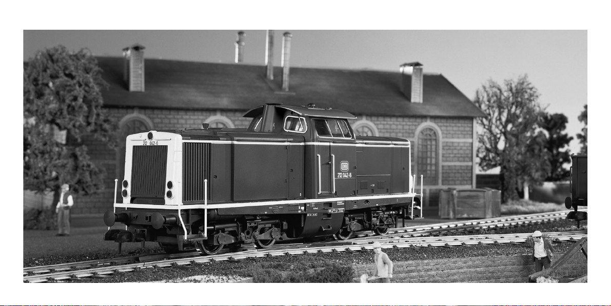
V100
Im ersten Typenprogramm der Deutschen Bundesbahn von 1955 wurden
verschiedene Lokmodelle definiert, die in den folgenden Jahren realisiert
werden sollten:
V 60 für den Rangierdienst
V 100 für den gemischten Nebenbahndienst
V 160 für den leichten Dienst auf Hauptstrecken
V 200 für den mittleren Dienst auf Hauptstrecken
V 320 für den schweren Dienst auf Hauptstrecken
Mit der Entwicklung der V 100 wurde 1956 begonnen. Ab 1958 wurden
insgesamt 364 Lokomotiven der Baureihe V 100
10
(später BR 211) ausgeliefert.
Anschließend wurde dieser Loktyp mit einem stärkeren Motor versehen und
mit einigen Modifikationen als V 10020(später BR 212, früher unter der
Nummer 5772 oder 5573 im Märklin-Programm) weiterproduziert.
Im Zeichen des Strukturwandels bei der DB sollte die V 100 vor allem die
Dampflokomotiven der Baureihen 64, 74 und 86 ersetzen. Eingesetzt wurde
sie fast überall in Deutschland auf nicht elektrifizierten Strecken. Mit einer
Leistung von 808 kW (1100 PS) erreichte die Lok eine Höchstgeschwindigkeit
von 100 km/h.
Wegen des ruhigen Laufes und der verbesserten Kurvengängigkeit wurde
die V 100 als Drehgestell-Lokomotive konzipiert. Der Mittelführerstand ist mit
2 Fahrpulten ausgerüstet.
Als Mädchen für Alles hat sich dieser Loktyp bei der DB ausgezeichnet
bewährt. In den achtziger Jahren begann der Verkauf mehrerer dieser
Maschinen an ausländische Bahnverwaltungen und Privatbahnen. Heute ist
nur noch die BR 212 im Lokbestand der Deutschen Bahn AG vorhanden.
Ihre zweite Karriere haben eine ganze Reihe dieser Lokomotiven inzwischen
bei diversen Privat-Bahnen oder Gleisbaufirmen begonnen.
1
5
Vorbild
Page 5

V100
Different locomotive models to be built in subsequent years were defined in
the German Federal Railroad’s first type classification program in 1955:
V 60 for switching work
V 100 for mixed branchline service
V 160 for light service on main lines
V 200 for medium service on amin lines
V 320 for heavy service on main lines
Development of the V 100 was started in 1956. From 1958 on a total of
364 class V 100
10
(later class 211) locomotives were delivered. This locomotive
was subsequently provided with a more powerful motor and additional units
were produced with modifications as the V 10020(later class 212, previously
in the Märklin assortment as numbers 5772 or 5573).
The V 100 was intended to replace chiefly the steam locomotive classes 64,
74 and 86 in the DB’s restructuring plans. It was employed alsmost everywhere
in Germany on non-electrified routes. It has an output of 808 kilowatts
(1,100 horsepower) and a maximum speed of 100 km/h (approx. 63 mph).
The V 100 was designed with trucks in the interests of smoother running and
better negotiation of curves. The center cab is equipped with two controllers.
This locomotive has proven itself very well on the DB as a jack-of-all-trades.
In the 1980s a number of these units were sold to foreign railroads and private
lines. At present only the class 212 is still on the motive power roster of the
German Railroad, Inc.
A whole series of these locomotives began their second career on different
privately owned railroads or track laying firms.
6
1
Prototype
Page 6

V100
Différents modèles de locomotives ont été définis dans le premier programme
de types de la Deutsche Bundesbahn de 1955. Ils devaient être réalisés au
cours de années suivantes:
V 60 pour le service de manceuvre
V 100 pour le service mixte sur les lignes secondaires
V 160 pour le sercvice léger sur des lignes principales
V 200 pour le service moyen sur des lignes principales
V 320 pour le service lourd sur des lignes principales
Le développement de la locomotive V 100 a commeneé en 1956. 364 locomotives de la série V 100
10
(future BR 211) ont en tout été livrées à partir de
1958. Ce type de locomotive a ensuite été pourvu d’un moteur plus puissant
et a continué à être produit avec quelques modifications, sous la désignation
V10020(future BR 212, autrefois disponible dans le programme Märklin sous
la référence 5772 ou 5573).
Sous le signe des mutations structurelles au sein des Chemins de fer de la
Deutsche Bundesbahn, la locomotive V 100 devait avant tout remplacer les
locomotives à vapeur des séries 64, 74 et 86. Elle a été utilisée pratiquement
partout en Allemagne, sur des voies non électrifiées. Avec une puissance de
808 kW (1100 CV), la locomotive atteignait une vitesse maximum de 100 km/h.
En raison de son fonctionnement clame et de sa tenue en courbes améliorée,
la locomotive V 100 a été conçue comme une locomotive à bogies. Le poste
de conduite central est épuipé de deux pupitres de conduite.
Ce type de locomotive a fait ses preuves comme «bonne à tout faire» des
chemins de fer de la Deutsche Bundesbahn. Au cours des années 80,
plusieurs de ces machines on été vendues à des chemins de fer publies et
privés étrangers. Aujourd’hui, seule la BR 212 se trouve encore dans le pare
de locomotives de la Deutsche Bahn AG.
Toute une série de ces locomotives a entamé une seconde carrière au service
de chemins de fer privés ou de firmes de travaux ferroviaires.
1
7
Exploitation dans le réel
Page 7

V100
In het eerste typenprogramma van de Deutsche Bundesbahn van 1955
werden verschillende lokmodellen gedefinieerd, die in de volgende jaren
gerealiseer moesten worden:
V 60 voor de rangeerdienst
V 100 voor de diensten op de zijlijnen
V 160 voor de lichte dienst op hoofdlijnen
V 200 voor de middelzware dienst op hoofdlijnen
V 320 voor de zware dienst op hoofdlijnen
Met de ontwikkeling van de V 100 werd in 1956 begonnen. Vanaf 1958 werden er in totaal 364 lokomotieven van de serie V 100
10
(de latere serie BR 211)
afgeleverd. Aansluitend werd dit loktype van een sterke motor voorzien en
met enkele modificaties als V 10020(de latere serie BR 212, vroeger onder
nummer 5772 of 5573 in het Märklin-programma) verder geproduceerd.
In het kader van de herstructurering bij de DB moest de V 100 vooral de
stroomlokomotieven van de series 64, 74 en 86 vervangen. Hij werd bijna
overal in Duitsland oip niet-geëlektrificeerde trajecten ondergebracht.
Met een vermogen van 808 kW (1100 pk) bereikte de lok een maximum
snelheid van 100 km/h.
Vanwege zijn rustige loop en de verbeterde loop in de bogen werd de V 100
als draaistellokomotief ontworpen. De middencabine is met tweee regeltafels
uitgevoerd.
Als meisje voor alle dag heeft dit loktype zich bij de DB uitstekend bewezen.
In de jaren tachtig begon de verkoop van diverse van deze machines aan
buitenlandse en particuliere spoorwegmaatschappijen. Heden ten dage is
alleen de BR 212 nog in het lokbestand van de Deutsche Bahn AG aanwezig.
Een groot aantal van deze locomotieven is intussen aan een tweede carrière
begonnen bij geprivatiseerde spoorwegmaatschappijen of spoorwegbouwbedrijven.
8
1
Grootbedrijf
Page 8

9
Betrieb
2.1 Funktion
Diese Lok mit eingebauter
Digital-Elektronik bietet:
• Wahlweiser konventioneller Betrieb
(Wechselstrom mit Transformer
32 VA oder Gleichstrom [max.
+/– 18 Volt=]), Betrieb mit Märklin
Delta (nur Delta Station 6607),
Märklin Digital (Control Unit) oder
Märklin Systems (Mobile Station
oder Central Station). Ein Betrieb
mit Fahrgeräten anderer Systeme
(z.B. Impulsbreitensteuerung,
Betrieb mit der Central Control 1
(6030) oder ähnlichem System)
ist nicht möglich.
• Automatische Erkennung zwischen
konventionellem Betrieb und
Mehrzug-Betrieb. Die Auswahl
zwischen Wechselspannung und
Gleichspannung beim konventionellen Betrieb wird manuell auf
der Platine eingestellt.
• 80 Märklin Systems / Digital(4 Delta-) Adressen über Codierschalter einstellbar. Eingestellte
Adresse ab Werk: 12.
• Einstellbare Höchstgeschwindigkeit.
• Einstellbare Anfahr-/ Bremsverzögerung. Bremsverzögerung im
konventionellen Betrieb systembedingt nicht wirksam.
• Fahrtrichtungsabhängige
Beleuchtung im Betrieb mit der
Control Unit, der Mobile Station
oder der Central Station ein-/ ausschaltbar. Bei konventionellem
Betrieb ist die Intensität der
Beleuchtung geschwindigkeitsabhängig. Bei Betrieb mit
Delta-Station ist die Spitzenbeleuchtung dauernd eingeschaltet.
• Eingebaute Geräuschelektronik,
bei der nur im Betrieb mit der
Control Unit, der Mobile Station
oder der Central Station das
Betriebsgeräusch oder separat
das Geräusch eines Signalhorns
eingeschaltet werden kann.
• Im Betrieb mit der Control Unit,
der Mobile Station oder der
Central Station kann die eingestellte
Anfahr- und Bremsverzögerung
als Schaltfunktion im Spielbetrieb
minimiert werden. Damit ergibt
sich z.B. eine sensiblere Steuerungsmöglichkeit beim Rangieren.
• Befahrbarer Mindestradius:
1020 mm.
• Das Modell ist für den Betrieb auf
dem Märklin Spur 1-Gleissystem
entwickelt. Ein Betrieb auf anderen
Gleissystemen geschieht auf
eigenes Risiko.
2
Page 9
Betrieb
10
2
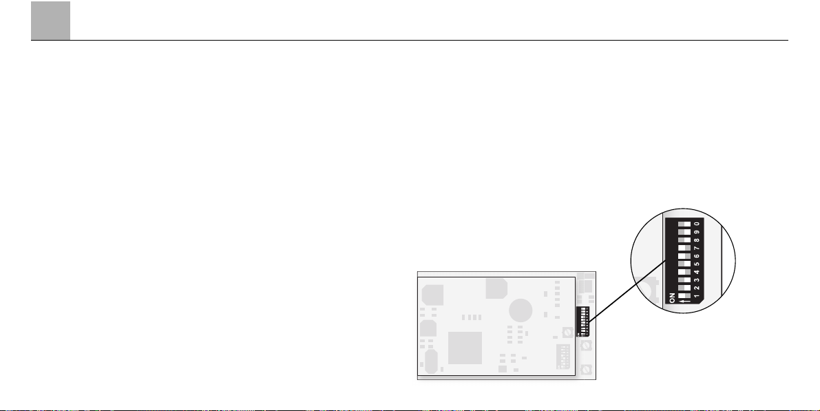
2.2 Lokparameter einstellen
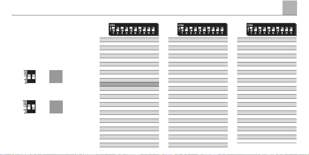
Die Betriebsart und die Mehrzugadresse wird an dem 10-fach-Codierschalter auf der Mehrzugelektronik
eingestellt.
Vorsicht! Den 10-fach Codierschalter für die Betriebsart und
für die Adresse auf der unteren
Digital-Platine nicht mit dem
8-fach Codierschalter auf der
oberen Soundplatine verwechseln!
2.2.1 Einstellen der Betriebsart
1. Gehäuse abnehmen (=> S. 42).
2. Codierschalter einstellen.
Schalter 10 (0) auf off:
Wechselspannung – Betrieb
Schalter 10 (0) auf on:
Gleichspannung – Betrieb
Der Mehrzugbetrieb
(Digital / Delta / Märklin Systems)
wird automatisch erkannt.
2.2.2 Mehrzug-Adresse einstellen
1. Gehäuse abnehmen (=> S. 42).
2. An den Schaltern 1 bis 8 des
Codierschalters die gewünschte
Adresse einstellen.
Beispiel: gewünschte Adresse 12.
Schalter 1, 4, 6, 7 auf on.
Schalter 2, 3, 5, 8 auf off.
Hinweis:
Schalter 9 muss immer auf off stehen.
Page 10
2
11
Betrieb
Digital
Digital
Digital
28 – 2 3 – 5 – – 8 –
*
29 – – 3 – 5 – – 8 –
*
30 1 – – 4 5 – – 8 –
*
31 – 2 – 4 5 – – 8 –
*
32 – – – 4 5 – – 8 –
*
33 1 – – – 5 – – 8 –
*
34 – 2 – – 5 – – 8 –
*
35 – – – – 5 – – 8 –
*
36 1 – 3 – – 6 – 8 –
*
37 – 2 3 – – 6 – 8 –
*
38 – – 3 – – 6 – 8 –
*
39 1 – – 4 – 6 – 8 –
*
40 – 2 – 4 – 6 – 8 –
*
41 – – – 4 – 6 – 8 –
*
42 1 – – – – 6 – 8 –
*
43 – 2 – – – 6 – 8 –
*
44 – – – – – 6 – 8 –
*
45 1 – 3 – – – – 8 –
*
46 – 2 3 – – – – 8 –
*
47 – – 3 – – – – 8 –
*
48 1 – – 4 – – – 8 –
*
49 – 2 – 4 – – – 8 –
*
50 – – – 4 – – – 8 –
*
51 1 – – – – – – 8 –
*
52 – 2 – – – – – 8 –
*
53 – – – – – – – 8 –
*
54 1 – 3 – 5 – – – –
*
55 – 2 3 – 5 – – – –
*
56 – – 3 – 5 – – – –
*
57 1 – – 4 5 – – – –
*
58 – 2 – 4 5 – – – –
*
59 – – – 4 5 – – – –
*
60 1 – – – 5 – – – –
*
61 – 2 – – 5 – – – –
*
62 – – – – 5 – – – –
*
63 1 – 3 – – 6 – – –
*
64 – 2 3 – – 6 – – –
*
65 – – 3 – – 6 – – –
*
66 1 – – 4 – 6 – – –
*
67 – 2 – 4 – 6 – – –
*
68 – – – 4 – 6 – – –
*
69 1 – – – – 6 – – –
*
70 – 2 – – – 6 – – –
*
71 – – – – – 6 – – –
*
72 1 – 3 – – – – – –
*
73 – 2 3 – – – – – –
*
74 – – 3 – – – – – –
*
75 1 – – 4 – – – – –
*
76 – 2 – 4 – – – – –
*
77 – – – 4 – – – – –
*
78 1 – – – – – – – –
*
79 – 2 – – – – – – –
*
80 1 – 3 – 5 – 7 – –
*
01 – 2 3 – 5 – 7 – –
*
02 – – 3 – 5 – 7 – –
*
03 1 – – 4 5 – 7 – –
*
04 – 2 – 4 5 – 7 – –
*
05 – – – 4 5 – 7 – –
*
06 1 – – – 5 – 7 – –
*
07 – 2 – – 5 – 7 – –
*
08 – – – – 5 – 7 – –
*
09 1 – 3 – – 6 7 – –
*
10 – 2 3 – – 6 7 – –
*
11 – – 3 – – 6 7 – –
*
12 1 – – 4 – 6 7 – –
*
13 – 2 – 4 – 6 7 – –
*
14 – – – 4 – 6 7 – –
*
15 1 – – – – 6 7 – –
*
16 – 2 – – – 6 7 – –
*
17 – – – – – 6 7 – –
*
18 1 – 3 – – – 7 – –
*
19 – 2 3 – – – 7 – –
*
20 – – 3 – – – 7 – –
*
21 1 – – 4 – – 7 – –
*
22 – 2 – 4 – – 7 – –
*
23 – – – 4 – – 7 – –
*
24 1 – – – – – 7 – –
*
25 – 2 – – – – 7 – –
*
26 – – – – – – 7 – –
*
27 1 – 3 – 5 – – 8 –
*
~
90
=
90
*
Je nach Stellung konventioneller
Wechselstrom (off)
Gleichstrombetrieb (on).
Page 11
2.2.3 Einstellen der Fahrparameter
1. Gehäuse abnehmen (=> S. 42).
2. Durch Verändern der Stellung der
Potis die entsprechenden Parameter
verändern. Die Drehpotis besitzen
an den Endpositionen jeweils
einen Anschlag. Daher bei Widerstand beim Drehen der Potis nicht
mit Gewalt weiterdrehen.
P1: Anfahr- / Bremsverzögerung
(gemeinsam)
Linksanschlag:
minimale Verzögerung.
Rechtsanschlag:
maximale Verzögerung.
P2: Höchstgeschwindigkeit
Linksanschlag:
minimale Höchstgeschwindigkeit.
Rechtsanschlag:
maximale Höchstgeschwindigkeit.
Hinweis:
Die beiden Potis zum Einstellen
der Fahrparameter auf der unteren
Digital-Platine nicht mit dem Poti
zur Lautstärkeregelung auf der
oberen Platine verwechseln.
12
2
Betrieb
P2
P1
Page 12
2
13
Betrieb
2.3 Betrieb mit den einzelnen
Versorgungs-Systemen
Dieses Modell ist zum wahlweisen
Betrieb mit Märklin Systems
(Mobile Station oder Central Station),
Märklin Digital (nur Control Unit als
Zentrale), Märklin Delta, Wechselstrom (nur Märklin Transformer 32 VA)
oder Gleichstrom (Fahrgerät mit
einer maximalen Spannung von
+/– 18 Volt =) geeignet. Schäden,
die beim Betrieb mit einem anderen
Betriebssystem entstehen, beruhen
auf einem nicht erlaubten Betriebszustand und sind daher nicht durch
die Gewährleistungspflicht oder die
Herstellergarantie abgedeckt. Für alle
hieraus entstehenden Schäden haftet
der Anwender.
2.3.1 Betrieb mit der Mobile Station/
Central Station
Zur Aufnahme dieser Lokomotive in
die Lokliste lesen Sie bitte die Gebrauchsanleitung zur Mobile Station
oder Central Station. Zur Anwahl
der Lokomotive aus der Datenbank
benutzen Sie bitte die Artikelnummer,
die Sie z. B. auf der Lokverpackung
finden. Folgende Schaltfunktionen
stehen Ihnen zur Verfügung:
• Fahrtrichtungsabhängige Beleuch-
tung ein/aus.
• Betriebsgeräusch (Motor, Neben-
aggregate etc.) ein/aus.
• Geräusch eines Signalhorns
ein/aus.
• Minimieren der Anfahr-/ Brems-
verzögerung.
2.3.2 Betrieb mit Digital
Hinweis:
Zum Fahrbetrieb können alle Märklin
Zentraleinheiten mit dem MotorolaÜbertragungsformat verwendet werden. Der volle Funktionsumfang steht
jedoch nur mit der Control Unit 6021
zur Verfügung. Bei Verwendung der
früheren Central Unit 6020 oder einer
baugleichen Version können die
Funktionen F1 bis F4 nicht geschaltet
werden. Es entfällt auch die Fahrtrichtungsanzeige.
Für einen einwandfreien Betrieb mit
der Control Unit 6021 müssen die
Codierschalter auf der Rückseite dieses
Gerätes in folgende Stellung gebracht
werden:
Schalter: 1 2 3 4
Stellung: on on on off
Fahrbetrieb mit der
Control Unit 6021:
Lokadresse eingeben. Drehen des
Fahrreglers nach rechts bis zum
Anschlag erhöht die Lokgeschwindigkeit. Drehen des Fahrreglers nach
links bis zur Stellung „0“ vermindert
die Lokgeschwindigkeit.
Page 13

14
2
Betrieb
Hinweis:
Je nach eingestellter Anfahr-/ Bremsverzögerung reagiert die Lok entsprechend zeitverzögert auf die neue
Vorgabe.
Drehen des Fahrreglers nach links
über die Stellung „0“ hinweg:
Fahrtrichtungswechsel.
Hinweis:
Die Fahrtrichtung wird bei der
Control Unit 6021 über zwei Pfeile
rechts neben der Adressanzeige
angezeigt.
Pfeil nach oben: Lok fährt vorwärts.
Pfeil nach unten: Lok fährt rückwärts.
Drücken der Taste „function“:
Einschalten der Beleuchtung.
Drücken der Taste „off“:
Ausschalten der Beleuchtung.
Drücken der Taste „f2“:
Einschalten der Geräuschelektronik
(Betriebsgeräusch).
Durch ein weiteres Betätigen der
Taste „f2“ wird das Geräusch wieder
ausgeschaltet.
Drücken der Taste „f3“:
Einschalten des Geräuschs eines
Signalhorns. Anschließend unbedingt durch ein weiteres Betätigen
der Taste „f3“ die Funktion ausschalten! Sonst kann es zu Fehlfunktionen kommen.
Ausgangszustand:
Kontroll – LED über der Taste „f4“
ist aus:
Drücken der Taste „f4“ ergibt:
Minimieren der eingestellten Anfahrund Bremsverzögerung.
Ausgangszustand:
Kontroll – LED über der Taste „f4“
leuchtet:
Drücken der Taste „f4“ ergibt:
Wiederherstellen der auf der DigitalElektronik eingestellten Anfahr- und
Bremsverzögerung.
2.3.3 Fahren der Lok mit Delta
Zum Fahren der Lok mit Märklin
Delta wird an dem Handregler
Delta-Mobil die eingestellte Lokadresse angewählt. Durch Drehen
des Fahrreglers aus der Mittelstellung
heraus nach rechts fährt die Lok vorwärts. Durch Drehen des Fahrreglers
aus der Mittelstellung nach links fährt
die Lok rückwärts. Die fahrtrichtungsabhängige Beleuchtung ist dauernd
eingeschaltet. Die maximale Ausgangsleistung der Delta-Station
reicht zum gleichzeitigen Fahren von
2 bis maximal 3 einmotorigen Lokomotiven.
Alle sonstigen Funktionen (Geräusch)
sind im Delta-Betrieb immer ausgeschaltet.
Page 14

2
15
Betrieb
2.3.4 Fahren mit Wechselspannung
In der Betriebsart „Wechselspannung“
kann die Lok z.B. mit dem Transformer 32 VA (Nr. 6645, 6646, 6647
oder 76648) gesteuert werden.
Durch Drehen des Fahrreglers nach
rechts wird die Geschwindigkeit der
Lok erhöht und durch Drehen nach
links wird sie entsprechend vermindert. Wird der Fahrregler über die
Stellung „0“ nach links weiter
gedreht, so wird die Fahrtrichtung
umgeschaltet. Der Umschaltbefehl
für die Fahrtrichtung sollte nie an eine
fahrende Lok sondern immer nur an
eine stehende Lok gegeben werden.
Alle sonstigen Funktionen (Geräusch)
sind im Wechselspannungs-Betrieb
immer ausgeschaltet.
2.3.5 Fahren mit Gleichspannung
Gleichspannungs-Fahrgeräte werden
von Märklin für Spur-1-Modelle nicht
angeboten. Geeignet sind Gleichspannungs-Fahrgeräte mit einer
maximalen Spannung von ±18 Volt.
Der Fahrtrichtungswechsel wird
durch einen Polaritätswechsel vorgenommen. Die Bedienung des jeweiligen Fahrgerätes entnehmen Sie der
Anleitung des Herstellers.
Hinweis:
H0-Gleichspannungs-Fahrgeräte
geben eine maximale Spannung von
±12 Volt ab. Die Lok erreicht jedoch
ihre volle Leistungsfähigkeit erst bei
±16 Volt. H0-Gleichspannungs-Fahrgeräte sind daher nur eingeschränkt
verwendbar.
Im Betrieb mit Gleichspannung ist die
fahrtrichtungsabhängige Beleuchtung
eingeschaltet. Die Intensität der Beleuchtung ist geschwindigkeitsabhängig.
Alle sonstigen Funktionen (Geräusch)
sind im Gleichspannungs-Betrieb
immer ausgeschaltet.
Page 15
16
2
Betrieb
2.4 Einstellen der
Geräuschelektronik
Entfernen Sie das Lokgehäuse
(=> S. 42). Die obere der beiden
Platinen ist die Sound-Elektronik, auf
der Sie nachfolgende Einstellungen
durchführen können.
2.4.1 Lautstärke einstellen
Hinweis: Dieses Poti befindet sich
auf der oberen Sound-Elektronik.
Verwechseln Sie auf keinen Fall
dieses Poti mit einem der Potis auf
der unteren Digital-Platine zum
Einstellen der Fahrparameter.
Drehen des Potis nach links: Leiser
Drehen des Potis nach rechts: Lauter
Das Poti besitzt an den Endpunkten
jeweils einen Anschlag. Versuchen
Sie nie mit Kraft das Poti über diesen
Anschlag hinweg zu drehen.
2.4.2 Codierschalter auf der
Sound-Elektronik
Die Soundelektronik wird mit dem
8-poligen Codierschalter auf das
jeweilige Modell abgestimmt. Die
passende Einstellung für Ihr Modell
ist dabei ab Werk eingestellt. Daher
ist keine Veränderung der Einstellung
notwendig.
Hinweis:
Dieser Codierschalter befindet
sich auf der oberen SoundElektronik. Verwechseln
Sie ihn auf keinen Fall mit dem
10-fach Codierschalter zum Einstellen der Adresse und Betriebsart auf der unteren DigitalElektronik.
Die Serieneinstellung der 8 Codierschalter ist:
Schalter 1 2 3 4 5 6 7 8
Stellung On On Off Off On On On On
Page 16

2.1 Function
This locomotive has a built-in digital
electronic circuit and offers the
following features:
• Optional conventional operation
(AC power with 32 VA transformer or
DC power [max. +/– 18 volts DC]),
operation with Märklin Delta
(only with the 6607 Delta Station),
Märklin Digital (Control Unit) or
Märklin Systems (Mobile Station
or Central Station). This locomotive
is not designed for operation with
locomotive controllers for other
systems (example: pulse width
control, operation with the
Central Control 1 (6030) or similar
systems).
• Automatic recognition of conventional operation and multi-train
operation. The choice between
AC or DC power in conventional
operation is set manually on the
circuit board.
• 80 Märklin Systems / Digital
(4 Delta) addresses can be set
with coding switches. Address
set at the factory: 12.
• Adjustable maximum speed.
• Adjustable acceleration/braking
delay. The electronic circuit for the
locomotive is designed in such a
way that the braking delay will not
work in conventional operation.
• Headlights change over with the
direction of travel in operation with
the Control Unit, the Mobile Station,
or the Central Station and can be
turned on/off. During conventional
operation the brightness of the
headlights depends on the speed
of the loco-motive. The headlights
are on constantly when the locomotive is operated with the
Delta Station.
• Built-in sound effects circuit, on
which the locomotive’s operating
sounds or the separate sound of
a horn can be turned on only in
operation with the Control Unit,
the Mobile Station, or the
Central Station.
• The acceleration and braking delay
that has been set can be turned
down to a minimum as a controllable function when operating the
locomotive with the Control Unit,
the Mobile Station, or the Central
Station. This gives you better control of the locomotive for switching
operations.
• Minimum radius for operation:
1.020 mm / 40-3/16“.
• This model has been developed
for operation on the Märklin 1
Gauge track system. You incur
your own risk operating it on other
track systems.
2
17
Operation
Page 17

2.2 Setting Locomotive
Parameters
The mode of operation and the
multi-train address are set with the
10 coding switches on the multi-train
electronic circuit.
Caution! Do not confuse the
10 coding switches for the mode
of operation and for the address
on the lower digital circuit board
with the 8 coding switches on the
upper sound effects circuit board!
2.2.1 Setting the Mode
of Operation
1. Removing the body (=> page 42).
2. Setting the coding switches.
Switch 10 (0) at off:
Operation with AC power
Switch 10 (0) at on:
Operation with DC power
The multi-train operation mode
(Digital / Delta / Märklin Systems)
is automatically recognized.
2.2.2 Setting a Multi-Train
Address
1. Removing the body (=> page 42).
2. Set the desired address with
switches 1 to 8.
Example: 12 is the desired address.
Switches 1, 4, 6, 7 at on.
Switches 2, 3, 5, 8 at off.
Important:
Switch 9 must always be set at off.
18
2
Operation
Page 18

2
19
Operation
~
90
=
90
*
Conventional AC power (off) or
DC power (on), depending on the
setting.
Digital
Digital
Digital
28 – 2 3 – 5 – – 8 –
*
29 – – 3 – 5 – – 8 –
*
30 1 – – 4 5 – – 8 –
*
31 – 2 – 4 5 – – 8 –
*
32 – – – 4 5 – – 8 –
*
33 1 – – – 5 – – 8 –
*
34 – 2 – – 5 – – 8 –
*
35 – – – – 5 – – 8 –
*
36 1 – 3 – – 6 – 8 –
*
37 – 2 3 – – 6 – 8 –
*
38 – – 3 – – 6 – 8 –
*
39 1 – – 4 – 6 – 8 –
*
40 – 2 – 4 – 6 – 8 –
*
41 – – – 4 – 6 – 8 –
*
42 1 – – – – 6 – 8 –
*
43 – 2 – – – 6 – 8 –
*
44 – – – – – 6 – 8 –
*
45 1 – 3 – – – – 8 –
*
46 – 2 3 – – – – 8 –
*
47 – – 3 – – – – 8 –
*
48 1 – – 4 – – – 8 –
*
49 – 2 – 4 – – – 8 –
*
50 – – – 4 – – – 8 –
*
51 1 – – – – – – 8 –
*
52 – 2 – – – – – 8 –
*
53 – – – – – – – 8 –
*
54 1 – 3 – 5 – – – –
*
55 – 2 3 – 5 – – – –
*
56 – – 3 – 5 – – – –
*
57 1 – – 4 5 – – – –
*
58 – 2 – 4 5 – – – –
*
59 – – – 4 5 – – – –
*
60 1 – – – 5 – – – –
*
61 – 2 – – 5 – – – –
*
62 – – – – 5 – – – –
*
63 1 – 3 – – 6 – – –
*
64 – 2 3 – – 6 – – –
*
65 – – 3 – – 6 – – –
*
66 1 – – 4 – 6 – – –
*
67 – 2 – 4 – 6 – – –
*
68 – – – 4 – 6 – – –
*
69 1 – – – – 6 – – –
*
70 – 2 – – – 6 – – –
*
71 – – – – – 6 – – –
*
72 1 – 3 – – – – – –
*
73 – 2 3 – – – – – –
*
74 – – 3 – – – – – –
*
75 1 – – 4 – – – – –
*
76 – 2 – 4 – – – – –
*
77 – – – 4 – – – – –
*
78 1 – – – – – – – –
*
79 – 2 – – – – – – –
*
80 1 – 3 – 5 – 7 – –
*
01 – 2 3 – 5 – 7 – –
*
02 – – 3 – 5 – 7 – –
*
03 1 – – 4 5 – 7 – –
*
04 – 2 – 4 5 – 7 – –
*
05 – – – 4 5 – 7 – –
*
06 1 – – – 5 – 7 – –
*
07 – 2 – – 5 – 7 – –
*
08 – – – – 5 – 7 – –
*
09 1 – 3 – – 6 7 – –
*
10 – 2 3 – – 6 7 – –
*
11 – – 3 – – 6 7 – –
*
12 1 – – 4 – 6 7 – –
*
13 – 2 – 4 – 6 7 – –
*
14 – – – 4 – 6 7 – –
*
15 1 – – – – 6 7 – –
*
16 – 2 – – – 6 7 – –
*
17 – – – – – 6 7 – –
*
18 1 – 3 – – – 7 – –
*
19 – 2 3 – – – 7 – –
*
20 – – 3 – – – 7 – –
*
21 1 – – 4 – – 7 – –
*
22 – 2 – 4 – – 7 – –
*
23 – – – 4 – – 7 – –
*
24 1 – – – – – 7 – –
*
25 – 2 – – – – 7 – –
*
26 – – – – – – 7 – –
*
27 1 – 3 – 5 – – 8 –
*
Page 19

2.2.3 Setting the Running
Characteristics Parameters
1. Removing the body (=> page 42).
2. The respective running characteris-
tics can be changed by changing
the setting on the potentiometers.
These potentiometers have a stop
at the end positions. When you
encounter resistance when turning
the “pots”, do not try to turn them
further with force.
P1: Acceleration / braking delay
(together)
Left stop: minimum delay
Right stop: maximum delay
P2: Maximum speed
Left stop:
lowest maximum speed
Right stop:
highest maximum speed
Important:
Do not confuse the two potentiometers for setting the running
characteristics on the lower digital
circuit board with the potentiometer for adjusting the volume of
the sound effects on the upper
circuit board.
20
2
Operation
P2
P1
Page 20

2
21
Operation
2.3 Operations with
Individual Power Systems
The model is designed for optional
operation with Märklin Systems
(Mobile Station or Central Station),
Märklin Digital (only with the
Control Unit as a Central Unit),
Märklin Delta, AC power (only with
the Märklin Transformer 32 VA), or
DC power (power pack with a maximum voltage of +/– 18 volts DC).
Damages caused by operating the
locomotive with another operating
system will be viewed as taking place
in a non-authorized operating status
and therefore are not covered by the
manufacturer’s warranty. The consumer assumes all responsibility for
damages resulting from this situation.
2.3.1 Operation with the Mobile
Station / Central Station
Please read the instructions for the
Mobile Station or Central Station to
enter this locomotive into the locomotive list. Please use the item number for the locomotive found on its
packaging to call it up from the database. The following auxiliary functions are available on this locomotive:
• Turning headlights on/off that
change over with the direction
of travel
• Turning locomotive operating
sounds (motor, auxiliary appliances,
etc.) on/off
• Turning the sound of a horn on/off
• Minimizing the acceleration /
braking delay
2.3.2 Operation with Digital
Important:
All of the Märklin central units with
the Motorola transmission format can
be used to run this locomotive. The
full range of functions is only available
with the 6021 Control Unit 6021.
Functions f1 through f4 cannot be
activated if you are using the earlier
Central Unit 6020 or a similar version.
The indicator for direction of travel is
also not present on these units.
The coding switches on the back of
the Control Unit 6021 must be set as
follows for trouble free operation:
Switch: 1 2 3 4
Setting: on on on off
Operating the locomotive with the
Control Unit 6021:
Entering the locomotive address.
Turning the speed control knob to
the right to the stop increases the
locomotive’s speed. Turning the
speed control knob to the left to the
"0” setting decreases the locomotive’s speed.
Page 21

Important:
There will be a delay in the locomotive’s reaction to each change in
speed, depending on how you have
set the acceleration/braking delay.
Turning the speed control knob to
the left past the “0” setting: Reverses
the locomotive’s direction of travel.
Important:
On the Control Unit 6021 two arrows
to the right of the address display
indicate the direction of travel for the
locomotive.
Arrow pointing up:
Locomotive runs forward.
Arrow pointing down:
Locomotive runs in reverse.
Pressing the “function” button:
Turns the headlights on.
Pressing the “off” button:
Turns the headlights off.
Pressing button “f2”:
Turns the sound effects circuit on
(locomotive operating sounds).
Pressing button “f2” again turns the
sound effects off.
Pressing button “f3”:
Turns the sound of a horn on. Now
quickly turn this function off by
pressing button “f3” again! Otherwise,
it can lead to malfunctions.
Starting status:
Indicator LED above button “f4” is off:
Pressing button “f4” does the following:
Minimizes the acceleration and braking
delay that has been set.
Starting status:
Indicator LED above button “f4” is on:
Pressing button “f4” does the following:
Turns the acceleration and braking
delay that has been set on the digital
electronic circuit back on.
2.3.3 Running the Locomotive
with Delta
To operate the locomotive with Märklin
Delta you use the Delta Mobil to select the address, that has been set on
the former. The locomotive will run
forward when you turn the speed
control knob to the right of the center
position. Turning the speed control
knob to the left of the center position
will cause the locomotive to run in
reverse. The headlights change
direction with the direction of travel
and are on all of the time. The
maximum power output of the
Delta Station is sufficient to operate
2 to a maximum of 3 single motor
locomotives at the same time.
All other functions (sound effects) are
always turned off in Delta operation.
22
2
Operation
Page 22

2.3.4 Operating with AC Power
When the locomotive is operated with
AC power in conventional operation,
the 32 VA transformer (no. 6645,
6646, 6647 or 76648) can be used.
Locomotive speed is increased by
turning the control knob to the right
and is decreased by turning the knob
to the left. The direction of travel is
changed by turning the control knob
to the left past the “0” setting.
The command to reverse should be
given only to a standing locomotive,
never to one in motion.In operation
with alternating current the headlights
change direction with the direction of
travel and are on all of the time. The
intensity of the headlights depends
on the speed of the locomotive.
All other functions (sound effects)
are always turned off in AC power
operation.
2.3.5 Operating with DC Power
Märklin does not offer DC power
packs for 1 Gauge models. Suitable
DC power packs are those with a
maximum current of ±18 volts.
Direction reversing is done by reversing polarity. The manufacturerís
instructions for a particular make of
power pack will give directions on
how to use it to operate a locomotive.
Tip:
H0 DC power packs supply a maximum voltage of ±12 volts. This locomotive reaches its full potential at
±16 volts. H0 DC power packs can
therefore be used only with limitations.
In operation with direct current the
headlights change direction with the
direction of travel and are on all of
the time. The intensity of the headlights depends on the speed of the
locomotive.
All other functions (sound effects)
are always turned off in DC power
operation.
2
23
Operation
Page 23

24
2
Operation
2.4 Adjusting the Sound
Effects Circuit
Remove the locomotive body
(=> Page 42). The upper circuit
board of the two circuit boards is the
sound effects electronic circuit on
which you can carry out the following
adjustments.
2.4.1 Adjusting Volume
Important: This potentiometer is
located on the upper sound
effects electronic circuit board.
Under no circumstances should
you confuse this potentiometer
with one of the potentiometers on
the lower digital circuit board for
adjusting the running characteristics of the locomotive.
Turning the potentiometer to the left:
softer
Turning the potentiometer to the right:
louder
This potentiometer has a stop at the
two end points. Never try to turn the
potentiometer with force past these
stops.
2.4.2 Coding Switches on the
Sound Effects Electronic
Circuit
The sound effects electronic circuit
is set up for each model with the
8 coding switches. The appropriate
settings for your model were made
at the factory. No changes in these
settings are therefore necessary.
Important: These coding switches
are located on the upper electronic
circuit for sound effects. Under no
circumstances should you confuse
them with the 10 coding switches
for setting the address and the
mode of operation on the lower
digital electronic circuit.
The 8 coding switches are set at the
factory as follows:
Switch 1 2 3 4 5 6 7 8
Setting On On Off Off On On On On
Page 24

2
25
Fonctionnement
2.1 Fonctionnement
Utilisation de cette locomotive
équipée d'une électronique Digital:
• Au choix, exploitation conventionnelle (courant alternatif avec
Transformer 32 VA ou courant
continu [max +/– 18 volts =]),
exploitation avec Märklin Delta
(uniquement Delta Station 6607),
Märklin Digital (Control Unit) ou
Märklin Systems (Mobile Station ou
Central Station). Une exploitation
à l’aide de régulateurs provenant
d’autres systèmes (par ex. courant
à impulsions de largeur variable,
Central Control 1 n° 6030 ou
systèmes similaires) n’est pas
possible.
• Détection automatique du mode
d’exploitation: exploitation conventionnelle ou exploitation multitrain.
La sélection entre le courant
alternatif et le courant continu
(en exploitation conventionnelle)
se fait manuellement sur la platine
électronique.
• 80 adresses Märklin Systems /
Digital (4 Delta) réglables via le
clavier d’encodage. Adresse
encodée en usine: 12.
• Vitesse maximale réglable.
• Temporisation d’accélérationfreinage réglable. La temporisation
de freinage n’est pas active en
exploitation conventionnelle.
• Eclairage des feux de signalisation,
avec inversion selon sens de
marche, activable/désactivable en
exploitation avec la Control Unit, la
Mobile Station ou la Central Station.
En exploitation conventionnelle,
l’intensité des feux dépend de la
vitesse (tension appliquée à la voie).
En exploitation avec la Station
Delta 6607, les feux sont activés
en permanence.
• Bruiteur électronique intégré permettant l’activation du bruitage de
moteur diesel ou du bruitage
séparé d’un avertisseur sonore
uniquement en exploitation avec la
Control Unit, la Mobile Station ou
la Central Station.
• En exploitation avec la Control Unit,
la Mobile Station ou la Central
Station, la fonction commutable
de temporisation d’accélérationfreinage peut être minimalisée afin
de permettre une sensibilité plus
grande du pilotage pour des
manœuvres aisées.
• Rayon minimal d’inscription en
courbe: 1020 mm.
• Le modèle réduit a été conçu pour
rouler sur les voies du système de
voies Märklin 1. Une exploitation
sur des voies d’autres systèmes
comporte des risques.
Page 25

2.2 Réglage des paramètres
de la locomotive
Le mode d’exploitation et l’adresse
multitrain peuvent être réglés à l’aide
du clavier de codage à 10 sélecteurs
de la platine électronique.
Attention! Ne pas confondre le
clavier de codage à 10 sélecteurs
pour réglage du mode d’exploitation et de l’adresse situé sur la
platine Digital inférieure avec le
clavier de codage à 8 sélecteurs
situé sur la platine de bruitage
supérieure!
2.2.1 Réglage du mode
d’exploitation
1. Enlever la caisse (=> page 42).
2. Régler le clavier d'encodage.
Sélecteur 10 (0) sur off:
exploitation en courant alternatif.
Sélecteur 10 (0) sur on:
exploitation en courant continu.
Le mode d’exploitation
(Digital / Delta / Märklin Systems)
est automatiquement détecté.
2.2.2 Réglage de l’adresse
multitrain
1. Enlever la caisse (=> page 42).
2. Régler l'adresse désirée à l'aide
des sélecteurs 1 à 8 du clavier
d'encodage.Exemple: adresse
souhaitée 12.
Sélecteurs 1, 4, 6, 7 sur on.
Sélecteurs 2, 3, 5, 8 sur off.
Remarque:
le sélecteur 9 doit toujours se trouver
sur off.
26
2
Fonctionnement
Page 26

2
27
Fonctionnement
~
90
=
90
*
Selon la position, courant conventionnel alternatif (off) ou courant conventionnel continu (on).
Digital
Digital
Digital
28 – 2 3 – 5 – – 8 –
*
29 – – 3 – 5 – – 8 –
*
30 1 – – 4 5 – – 8 –
*
31 – 2 – 4 5 – – 8 –
*
32 – – – 4 5 – – 8 –
*
33 1 – – – 5 – – 8 –
*
34 – 2 – – 5 – – 8 –
*
35 – – – – 5 – – 8 –
*
36 1 – 3 – – 6 – 8 –
*
37 – 2 3 – – 6 – 8 –
*
38 – – 3 – – 6 – 8 –
*
39 1 – – 4 – 6 – 8 –
*
40 – 2 – 4 – 6 – 8 –
*
41 – – – 4 – 6 – 8 –
*
42 1 – – – – 6 – 8 –
*
43 – 2 – – – 6 – 8 –
*
44 – – – – – 6 – 8 –
*
45 1 – 3 – – – – 8 –
*
46 – 2 3 – – – – 8 –
*
47 – – 3 – – – – 8 –
*
48 1 – – 4 – – – 8 –
*
49 – 2 – 4 – – – 8 –
*
50 – – – 4 – – – 8 –
*
51 1 – – – – – – 8 –
*
52 – 2 – – – – – 8 –
*
53 – – – – – – – 8 –
*
54 1 – 3 – 5 – – – –
*
55 – 2 3 – 5 – – – –
*
56 – – 3 – 5 – – – –
*
57 1 – – 4 5 – – – –
*
58 – 2 – 4 5 – – – –
*
59 – – – 4 5 – – – –
*
60 1 – – – 5 – – – –
*
61 – 2 – – 5 – – – –
*
62 – – – – 5 – – – –
*
63 1 – 3 – – 6 – – –
*
64 – 2 3 – – 6 – – –
*
65 – – 3 – – 6 – – –
*
66 1 – – 4 – 6 – – –
*
67 – 2 – 4 – 6 – – –
*
68 – – – 4 – 6 – – –
*
69 1 – – – – 6 – – –
*
70 – 2 – – – 6 – – –
*
71 – – – – – 6 – – –
*
72 1 – 3 – – – – – –
*
73 – 2 3 – – – – – –
*
74 – – 3 – – – – – –
*
75 1 – – 4 – – – – –
*
76 – 2 – 4 – – – – –
*
77 – – – 4 – – – – –
*
78 1 – – – – – – – –
*
79 – 2 – – – – – – –
*
80 1 – 3 – 5 – 7 – –
*
01 – 2 3 – 5 – 7 – –
*
02 – – 3 – 5 – 7 – –
*
03 1 – – 4 5 – 7 – –
*
04 – 2 – 4 5 – 7 – –
*
05 – – – 4 5 – 7 – –
*
06 1 – – – 5 – 7 – –
*
07 – 2 – – 5 – 7 – –
*
08 – – – – 5 – 7 – –
*
09 1 – 3 – – 6 7 – –
*
10 – 2 3 – – 6 7 – –
*
11 – – 3 – – 6 7 – –
*
12 1 – – 4 – 6 7 – –
*
13 – 2 – 4 – 6 7 – –
*
14 – – – 4 – 6 7 – –
*
15 1 – – – – 6 7 – –
*
16 – 2 – – – 6 7 – –
*
17 – – – – – 6 7 – –
*
18 1 – 3 – – – 7 – –
*
19 – 2 3 – – – 7 – –
*
20 – – 3 – – – 7 – –
*
21 1 – – 4 – – 7 – –
*
22 – 2 – 4 – – 7 – –
*
23 – – – 4 – – 7 – –
*
24 1 – – – – – 7 – –
*
25 – 2 – – – – 7 – –
*
26 – – – – – – 7 – –
*
27 1 – 3 – 5 – – 8 –
*
Page 27

2.2.3 Réglage des paramètres
de marche
1. Enlever la caisse (=> page 42).
2. Modifier les paramètres en agis-
sant sur les potentiomètres. Les
potentiomètres rotatifs possèdent
une butée en fin de course.
Donc, ne pas forcer la rotation dès
qu'une résistance se fait sentir.
P1: Temporisation d'accélération-
freinage (commune).
A fond contre la butée gauche:
temporisation minimale.
A fond contre la butée droite:
temporisation maximale.
P2: Vitesse maximale.
A fond contre la butée gauche:
valeur minimale.
A fond contre la butée droite:
valeur maximale.
Remarque: Ne pas confondre les
deux potentiomètres pour le réglage des paramètres de marche
situés sur la platine Digital
inférieure avec le potentiomètre
pour le réglage du niveau sonore
situé sur la platine supérieure!
28
2
Fonctionnement
P2
P1
Page 28

2.3 Exploitation avec divers
systèmes d’exploitation
Ce modèle convient pour une exploitation au choix avec Märklin Systems
(Mobile Station ou Central Station),
Märklin Digital (uniquement Control
Unit en tant que centrale), Märklin
Delta, en courant alternatif (uniquement Märklin Transformer 32 VA)
ou en courant continu (régulateur
avec une tension maximale de
+/– 18 volts =). Des dommages qui
surviendraient lors d’une exploitation
à l’aide d’autres systèmes d’exploitation seraient considérés comme
résultant d’une forme d’exploitation
non autorisée et ne seraient par
conséquent pas couverts par la
garantie du fabricant. Dans ce cas,
l’utilisateur serait considéré comme
entièrement responsable des dommages survenus.
2.3.1 Exploitation avec la Mobile
Station / la Central Station
Pour saisir cette locomotive dans la
liste des locomotives, suivez les
instructions données dans le mode
d’emploi de la Mobile Station ou de
la Central Station. Pour sélectionner
la locomotive dans la banque de
données, veuillez utiliser le numéro
d’article qui se trouve entre autres sur
la boîte d’emballage. Les fonctions
suivantes sont à votre disposition:
• Eclairage de feux de signalisation
avec inversion selon le sens de
marche activé/désactivé.
• Bruitage (moteur, groupes auxili-
aires, etc.) activé/désactivé.
• Bruitage d’un avertisseur sonore
activé/désactivé.
• Minimalisation de la temporisation
d’accélération-freinage.
2.3.2 Exploitation avec Digital
Remarque:
Toutes les unités centrales Märklin
fonctionnant avec le format de données Motorola peuvent être utilisées
pour l'exploitation des trains. Cependant, la totalité des fonctions n'est
disponible qu'avec la Control Unit 6021.
En cas d'utilisation de l'ancienne
Central Unit 6020 ou d'une version
similaire, les fonctions f1 à f4 ne peuvent pas être commutées. En outre,
l'indication de sens de marche ne
fonctionne pas.
Pour une exploitation impeccable
avec la Control Unit 6021, le clavier
d'encodage situé sur la face arrière
de l'appareil doit être réglé comme
suit:
Sélecteur: 1 2 3 4
Position: on on on off
Exploitation avec la
Control Unit 6021:
Introduire l'adresse de locomotive.
Tourner le bouton de réglage de
vitesse vers la droite jusqu'à la butée
augmente la vitesse de la locomotive.
Tourner le bouton de réglage de
vitesse vers la gauche jusqu'à la
position „0“ diminue la vitesse de la
locomotive.
2
29
Fonctionnement
Page 29

Remarque:
La locomotive réagit avec un temps
de réponse conforme au réglage
de la temporisation d'accélérationfreinage encodée.
Tourner le bouton de réglage en
passant outre la position „0“ change
le sens de marche.
Remarque:
Sur la Control Unit 6021, le sens de
marche est indiqué par les deux
flèches situées à droite de l'indicateur d'adresse.
Flèche vers le haut:
le locomotive roule en avant.
Flèche vers le bas:
le locomotive roule en arrière.
Presser la touche „function“:
activation des feux de signalisation.
Presser la touche „off“: désactivation
des feux de signalisation.
Une pression sur la touche „f2“:
Activation du bruitage (de marche).
Une autre pression sur la touche „f2“
désactive le bruitage.
Une pression sur la touche „f3“:
Activation du bruitage de l’avertisseur
sonore suivie ensuite impérativement
d’une autre pression sur la touche
„f3“ pour désactiver le bruitage sous
peine de provoquer un
dysfonctionnement!
Etat initial: témoin lumineux
de la touche „f4“ éteint:
Une pression sur la touche „f4“ a
pour effet de minimaliser la temporisation d’accélération-freinage encodée.
Etat initial: témoin lumineux
de la touche „f4“ allumé:
Une pression sur la touche „f4“ a
pour effet de remettre en service la
temporisation d’accélération-freinage
encodée dans l’électronique Digital.
2.3.3 Exploitation avec Delta
L'adresse qui a été réglée pour la
locomotive est choisie sur le régulateur manuel Delta-Mobil pour permettre à la locomotive de fonctionner
en Märklin Delta. Si l’on actionne le
régulateur de conduite de la position
centrale vers la droite, la locomotive
se déplace en marche avant. Si l'on
actionne le régulateur de conduite
de la position centrale vers la gauche,
la locomotive se déplace en marche
arrière. L'éclairage en fonction du
sens de la marche est constamment
enclenché. La puissance de sortie
maximum de la Delta-Station est
suffisante pour une exploitation
simultanée de 2 à 3 locomotives
à un seul moteur.
Toutes les autres fonctions (bruitage)
sont toujours désactivées en
exploitation Delta.
30
2
Fonctionnement
Page 30

2.3.4 Exploitation avec du
courant alternatif
Dans le mode d'exploitation „courant
alternatif“, la locomotive peut être
pilotée par exemple avec le Transformer 32 VA (n° 6645, 6646, 6647
ou 76648). En tournant le régulateur
de vitesse vers la droite, la vitesse
de la locomotive est augmentée, en
le tournant vers la gauche elle est
réduite en conséquence. Si le régulateur est tourné au-delà de la position «0» vers la gauche, le sens de la
marche est inversé. La commande
d'inversion du sens de la marche ne
devrait jamais être transmise à une
locomotive en circulation, mais toujours à une locomotive se trouvant
à l‘ arrêt.
Toutes les autres fonctions (bruitage)
sont toujours désactivées en
exploitation à courant alternatif.
2.3.5 Exploitation avec du
courant contçinu
Les règulateurs de vitesse à tension
continue ne sont pas proposés par
Märklin pour les modèles de Voie 1.
Les régulateurs de vitesse à tension
continue ayant une tension maximale
de ±18 volt sont adaptés. Le changement du sens de la marche est
réalisé grâce à un changement de
polarité. Vous trouverez les instructions de commande relatives aux différents régulateurs de vitesse dans la
notice du fabricant.
Indication:
Les régulateurs de vitesse H0 à tension continue fournissent une tension
maximum de ±12 volt. La locomotive
n'atteint cependant sa pleine capacité qu'avec ±16 volt. Les régulateurs
de vitesse H0 à tension continue ne
peuvent donc être utilisés qu'avec
certaines restrictions.
L'éclairage en fonction du sens de la
marche est enclenché en exploitation
sous tension continue. L'intensité de
léclairage dépend de la vitesse.
Toutes les autres fonctions (bruitage)
sont toujours désactivées en
exploitation à courant continu.
2
31
Fonctionnement
Page 31

2.4 Réglage du bruiteur
Retirez la carrosserie de la locomotive
(=> page 42). La platine supérieure
est la platine de bruitage sur laquelle
on peut procéder aux réglages
suivants.
2.4.1 Réglage du niveau sonore
Remarque: Ce potentiomètre se
trouve sur la platine de bruitage
supérieure. En aucun cas, ne pas
le confondre avec l’un des deux
potentiomètres pour le réglage
des paramètres de marche situés
sur la platine Digital inférieure.
Tourner le potentiomètre vers la
gauche: niveau sonore plus bas
Tourner le potentiomètre vers la
droite: niveau sonore plus élevé
Le potentiomètre possède une butée
à chaque extrémité. Veillez à ne
jamais forcer ces butées en tournant
le potentiomètre!
2.4.2 Clavier de codage sur la
platine de bruiteur
L’électronique de bruitage est réglée
à l’aide du clavier de codage à 8
sélecteurs logé dans le modèle. Le
réglage optimum de votre modèle a
été réalisé en usine. Par conséquent,
il n’y a pas lieu de modifier le réglage.
Remarque:
ce clavier de codage se trouve
sur la platine de bruitage supérieure. En aucun cas, ne le confondez pas avec le clavier de codage
à 10 sélecteurs pour réglage de
l’adresse et du mode d’exploitation qui se trouve sur la platine
inférieure.
Le réglage en usine du clavier de
codage à 8 sélecteurs est le suivant:
Sélecteur 1 2 3 4 5 6 7 8
Position On On Off Off On On On On
32
2
Fonctionnement
Page 32

2.1 Werking
Deze loc met ingebouwde digitaalelektronica biedt u:
• Naar keuze conventioneel bedrijf
(wisselstroom met de Transformer
32 VA of gelijkstroom
[max +/– 18 Volt=]), bedrijf met
Märklin Delta (alleen het
Delta Station 6607), Märklin Digital
(Control Unit) of het Märklin
Systems (Mobile Station of
Central Station). Het bedrijf met
rijregelaars van andere systemen
(bijv. impulsbreedte sturing,
gebruik van de Central-Control 1
(6030) of een dergelijk systeem) is
niet mogelijk.
• Automatische herkenning tussen
het conventionele en het meertreinen-bedrijf. De keuze tussen
wissel- of gelijkspanning in het
conventionele bedrijf moet handmatig op de print worden ingesteld.
• 80 Märklin Systems / Digital(4 Delta-) adressen instelbaar met
de codeerschakelaar. Vanaf de
fabriek is het adres 12 ingesteld.
• Instelbare maximumsnelheid.
• Instelbare optrek- afremvertraging.
Afremvertraging werkt niet bij
conventioneel bedrijf.
• Rijrichtingafhankelijke verlichting, in
het bedrijf met de Control Unit, het
Mobile Station of Central Station,
in- en uitschakelbaar. Bij conventioneel bedrijf is de intensiteit
van de verlichting afhankelijk van
de snelheid. Bij het bedrijf met
Delta Station is de frontverlichting
continu ingeschakeld.
• Ingebouwde geluidselektronica,
waarbij alleen in het bedrijf met de
Control Unit, het Mobile Station of
Central Station, het bedrijfsgeluid
en/of het geluid van een signaalhoorn apart ingeschakeld kan
worden.
• In het bedrijf met de Control Unit,
het Mobile Station of Central Station
kan de ingestelde optrek- en
afremvertraging als schakelfunctie
in het spelbedrijf geminimaliseerd
worden. Hierdoor is bijvoorbeeld
een nauwkeurige besturing mogelijk bij het rangeren.
• Berijdbare minimumradius:
1020 mm.
• Het model is ontwikkeld voor het
gebruik op het Märklin Spoor 1
railsysteem. Het gebruik op een
ander railsysteem geschied op
eigen risico.
2
33
Exploitatie
Page 33

2.2 Locomotief parameter
instellen
Het bedrijfssysteem en het meer-treinen adres wordt met de 10-voudige
codeerschakelaar op de meer-treinen
elektronica ingesteld.
Pas op! De 10-voudige codeerschakelaar voor het bedrijfssysteem en voor het adres op de
onderste printplaat niet verwisselen met de 8-voudige
codeerschakelaar op de bovenste
geluidsgenerator printplaat.
2.2.1 Instellen van het
bedrijfssysteem
1. Kap verwijderen (zie pag. 42).
2. Codeerschakelaar instellen.
Schakelaar 10 (0) op off:
wisselspanningsbedrijf.
Schakelaar 10 (0) op on:
gelijkspanningsbedrijf.
Het meer-treinen bedrijf
(Digital / Delta / Märklin Systems)
wordt automatisch herkend.
2.2.2 Meer-treinen adres instellen
1. Kap verwijderen (zie pag. 42).
2. Met de schakelaars 1 t/m 8 van de
codeerschakelaar het gewenste
adres instellen.
Voorbeeld: gewenst adres 12.
Schakelaar 1, 4, 6, 7 op on en.
Schakelaar 2, 3, 5, 8 op off.
Opmerking:
Schakelaar 9 moet altijd op off staan.
34
2
Exploitatie
Page 34

2
35
Exploitatie
~
90
=
90
*
afhankelijk van de conventionele instelling op wisselstroom (off) of
gelijkstroom (on).
Digital
Digital
Digital
28 – 2 3 – 5 – – 8 –
*
29 – – 3 – 5 – – 8 –
*
30 1 – – 4 5 – – 8 –
*
31 – 2 – 4 5 – – 8 –
*
32 – – – 4 5 – – 8 –
*
33 1 – – – 5 – – 8 –
*
34 – 2 – – 5 – – 8 –
*
35 – – – – 5 – – 8 –
*
36 1 – 3 – – 6 – 8 –
*
37 – 2 3 – – 6 – 8 –
*
38 – – 3 – – 6 – 8 –
*
39 1 – – 4 – 6 – 8 –
*
40 – 2 – 4 – 6 – 8 –
*
41 – – – 4 – 6 – 8 –
*
42 1 – – – – 6 – 8 –
*
43 – 2 – – – 6 – 8 –
*
44 – – – – – 6 – 8 –
*
45 1 – 3 – – – – 8 –
*
46 – 2 3 – – – – 8 –
*
47 – – 3 – – – – 8 –
*
48 1 – – 4 – – – 8 –
*
49 – 2 – 4 – – – 8 –
*
50 – – – 4 – – – 8 –
*
51 1 – – – – – – 8 –
*
52 – 2 – – – – – 8 –
*
53 – – – – – – – 8 –
*
54 1 – 3 – 5 – – – –
*
55 – 2 3 – 5 – – – –
*
56 – – 3 – 5 – – – –
*
57 1 – – 4 5 – – – –
*
58 – 2 – 4 5 – – – –
*
59 – – – 4 5 – – – –
*
60 1 – – – 5 – – – –
*
61 – 2 – – 5 – – – –
*
62 – – – – 5 – – – –
*
63 1 – 3 – – 6 – – –
*
64 – 2 3 – – 6 – – –
*
65 – – 3 – – 6 – – –
*
66 1 – – 4 – 6 – – –
*
67 – 2 – 4 – 6 – – –
*
68 – – – 4 – 6 – – –
*
69 1 – – – – 6 – – –
*
70 – 2 – – – 6 – – –
*
71 – – – – – 6 – – –
*
72 1 – 3 – – – – – –
*
73 – 2 3 – – – – – –
*
74 – – 3 – – – – – –
*
75 1 – – 4 – – – – –
*
76 – 2 – 4 – – – – –
*
77 – – – 4 – – – – –
*
78 1 – – – – – – – –
*
79 – 2 – – – – – – –
*
80 1 – 3 – 5 – 7 – –
*
01 – 2 3 – 5 – 7 – –
*
02 – – 3 – 5 – 7 – –
*
03 1 – – 4 5 – 7 – –
*
04 – 2 – 4 5 – 7 – –
*
05 – – – 4 5 – 7 – –
*
06 1 – – – 5 – 7 – –
*
07 – 2 – – 5 – 7 – –
*
08 – – – – 5 – 7 – –
*
09 1 – 3 – – 6 7 – –
*
10 – 2 3 – – 6 7 – –
*
11 – – 3 – – 6 7 – –
*
12 1 – – 4 – 6 7 – –
*
13 – 2 – 4 – 6 7 – –
*
14 – – – 4 – 6 7 – –
*
15 1 – – – – 6 7 – –
*
16 – 2 – – – 6 7 – –
*
17 – – – – – 6 7 – –
*
18 1 – 3 – – – 7 – –
*
19 – 2 3 – – – 7 – –
*
20 – – 3 – – – 7 – –
*
21 1 – – 4 – – 7 – –
*
22 – 2 – 4 – – 7 – –
*
23 – – – 4 – – 7 – –
*
24 1 – – – – – 7 – –
*
25 – 2 – – – – 7 – –
*
26 – – – – – – 7 – –
*
27 1 – 3 – 5 – – 8 –
*
Page 35

36
2
Exploitatie
2.2.3 Instellen van de rijparameters
1. Kap verwijderen (zie pag. 42).
2. Door het verdraaien van de instelling van de potentiometers de
overeenkomstige parameter wijzigen. De potentiometers hebben
aan beide eindposities een eindaanslag. Daarom bij enige weerstand, de potentiometers, niet met
geweld doordraaien.
P1: Optrek- / afremvertraging
(gemeenschappelijk)
Linkeraanslag:
minimale vertraging.
Rechteraanslag:
maximale vertraging.
P2: Maximumsnelheid
Linkeraanslag:
minimale maximumsnelheid.
Rechteraanslag:
maximale maximumsnelheid.
Opmerking:
de beide potentiometers voor het
instellen van het rijgedrag op de
onderste printplaat niet
verwisselen met de potentiometer
voor het geluidsvolume op de
bovenste printplaat.
P2
P1
Page 36

2
37
Exploitatie
2.3 Het bedrijf met de ver-
schillende bedrijfssystemen
Dit model is geschikt voor het
bedrijf met het Märklin Systems
(Mobile Station of Central Station),
Märklin Digital (alleen met de
Control Unit als centrale), Märklin
Delta, wisselstroom (alleen met de
Märklin Transformer 32 VA) of gelijkstroom (rijregelaar met een maximale
spanning van +/– 18 Volt=). Schade,
ontstaan bij het gebruik op andere
bedrijfssystemen, zijn terug te voeren
op een niet toegestane bedrijfstoestand en vallen daarom niet onder de
verantwoordelijkheid van de fabrikant
of de fabrieksgarantie. Voor alle daaruit ontstane schade is de gebruiker
verantwoordelijk.
2.3.1 Het bedrijf met het Mobile
Station / Central Station
Lees voor het opnemen van deze
locomotief in de locomotieflijst a.u.b.
eerst de gebruiksaanwijzing van het
Mobile Station of het Central Station.
Voor het kiezen van de locomotief uit
de databank gebruikt u het artikelnummer dat u bijv. op de locomotiefverpakking kunt vinden. De volgende
schakelfuncties staan u ter beschikking:
• Rijrichtingafhankelijke verlichting
aan / uit.
• Bedrijfsgeluiden (motor, neven-
aggregaten e.d.) aan / uit.
• Geluid van een signaalhoorn
aan / uit.
• Minimaliseren van de optrek- /
afremvertraging.
2.3.2 Bedrijf met Digital
Opmerking:
voor het rijden kunnen alle Märklin
centrales met het Motorola-formaat
gebruikt worden. Het benutten van
alle mogelijkheden is alleen met de
Control Unit 6021 mogelijk. Bij het gebruik van de oudere Central Unit 6020
of een gelijkwaardige versie kunnen
de functies f1 t/m f4 niet geschakeld
worden. Tevens ontbreekt de
rijrichtingsweergave.
2.3.2 Bedrijf met Digital
Om zonder problemen alle functies
aan te kunnen sturen, moeten de
schakelaars op de achterzijde van de
Control Unit op de volgende wijze
ingesteld worden:
Schakelaar: 1234
Stand: on on on off
Rijden met de Control Unit 6021:
Loc adres invoeren.
Door de regelknop naar rechts, tot
aan de aanslag, te draaien wordt de
snelheid van de locomotief verhoogt.
Het verdraaien van de regelknop
naar links, tot aan de stand „0” verminderd de snelheid van de loc.
Page 37

Opmerking:
afhankelijk van de ingestelde optrek/afremvertraging, reageert de loc vertraagd op de verdraaiing van de
regelknop naar de nieuwe stand.
Het verdraaien van de regelknop
naar links, door de stand „0”:
omkeren van de rijrichting.
Opmerking:
de rijrichting wordt bij de Control Unit
6021 via de rijrichtingspijlen, naast
het adres, weergegeven.
Pijl naar boven: loc rijdt vooruit.
Pijl naar beneden: loc rijdt achteruit.
Druk op de toets „function”:
inschakelen van de verlichting.
Druk op de toets „off”:
uitschakelen van de verlichting.
Indrukken van toets “f2“:
inschakelen van de geluidelektronica
(bedrijfsgeluiden). Door nogmaals op
de toets “f2“ te drukken wordt het
geluid weer uitgeschakeld.
Indrukken van toets “f3“: inschakelen
van het geluid van een signaalhoorn.
Aansluitend beslist nogmaals op de
toets “f3“ drukken om de functie
weer uit te schakelen! Anders kan er
functieverstoring ontstaan.
Uitgangstoestand: controle LED
boven de toets “f4” is uit:
het indrukken van de toets heeft
tot gevolg:
minimaliseren van de ingestelde
optrek- en afremvertraging.
Uitgangstoestand: controle LED
boven de toets “f4” brand:
het indrukken van de toets heeft
tot gevolg:
herstellen van de op de digitale
decoder ingestelde optrek- en afremvertraging.
2.3.3 Rijden met de loc met Delta
Om met de loc binnen Märklin Delta
te kunnen rijden, wordt op de handregelaar Delta-Mobil het ingestelde
locadres gekozen. Door draaien aan
de rijregelaar vanuit de middenstand
naar rechts rijdt de loc vooruit. Door
draaien aan de rijregelaar venuit de
middenstand naar links rijdt de loc
achteruit. De rijrichtingafhankelijke
verlichting is constant ingeschakeld.
Het maximale uitgangsvermogen van
het Delta-Station is voldoende om
tegelijk met 2 à 3 eenmotorige locomotieven te laten rijden.
Alle andere functies (geluid) zijn in
Delta-bedrijf altijd uitgeschakeld.
38
2
Exploitatie
Page 38

2.3.4 Rijden met wisselspanning
Bij het wisselstroombedrijf kan de loc
bijv. met de transformator 32VA
(nr. 6645, 6646, 6648 of 76648)
bestuurd worden. Door de rijregelaar
naar rechts te draaien versnelt de loc
en naar links vermindert de snelheid.
Als de rijregelaar door de stand „0”
heen verder naar links gedraaid
wordt, dan wordt de rijrichting omgeschakeld. Het omschakelbevel voor
de rijrichting mag nooit aan een rijdende loc, maar altijd alleen aan een
stilstaande loc gegeven worden.
Bij gebruik met wisselspanning is de
rijrichtingafhankelijke verlichting ingeschakeld. De helderheid van de verlichting is afhankelijk van de snelheid.
Alle andere functies (geluid) zijn in
wisselspanningsbedrijf altijd uitgeschakeld.
2.3.5 Rijden met gelijkspanning
Rijregelaars voor gelijkspanning worden door Märklin niet voor spoor 1modellen aangeboden. Geschikte
rijregelaars voor gelijkspanning leveren een maximale spanning van ±18
volt. De wisseling van de rijrichting
wordt door ompolen bewerksstelligd.
De bediening van uw arijregelaar leest
u in de handleiding van de fabrikant.
Opmerking:
H0-gelijkspanningsapparaten geven
een maximale spanning van ±12 volt
af. De loc bereikt zijn volle vermogen
echter pas bij ±16 volt.
H0-gelijkspanningsapparaten zijn
daardoor slechts beperkt abruikbaar.
Bij gebruik met gelijkspanning is de
rijrichtingafhankelijke verlichting ingeschakeld. De helderheid van de verlichting is afhankelijk van de snelheid.
Alle andere functies (geluid) zijn in
gelijkstroombedrijf altijd uitgeschakeld.
2
39
Exploitatie
Page 39

2
Exploitatie
2.4 Instellen van de
geluidselektronica
Afnemen van de loc kap (blad-zijde 42).
De bovenste van de beiden printplaten is de geluidsgenerator waarop
u de volgende instellingen kunt
uitvoeren.
2.4.1 Geluidsvolume instellen
Opmerking: de potentiometer
bevindt zich op de bovenste printplaat. Verwissel deze potentio-
meter in geen geval met één van
de potentiometers op de onderste
printplaat voor het instellen van
het rijgedrag.
Draai de potentiometer naar links:
zachter
Draai de potentiometer naar rechts:
luider
De potentiometers hebben op de
eindpunten een aanslag. Probeer niet
met kracht door deze aanslag heen
te draaien.
2.4.2 Codeerschakelaar op de
geluidsprintplaat
De geluidselektronica wordt met de
8-voudige codeerschakelaar afgestemd op het model. De juiste
instelling voor uw model is in de
fabriek reeds optimaal ingesteld.
Daarom is wijziging van deze instelling
niet noodzakelijk.
Opmerking:
de 8-voudige codeerschakelaar
bevindt zich op de bovenste
printplaat. Verwissel deze
codeerschakelaar in geen geval
met de 10-voudige
codeerschakelaar op de onderste
printplaat voor het instellen van
het bedrijfssysteem/ digitaaladres.
De seriematige instelling van de
8 codeerschakelaars is:
Schakelaar 1 2 3 4 5 6 7 8
Stand On On Off Off On On On On
40
Page 40

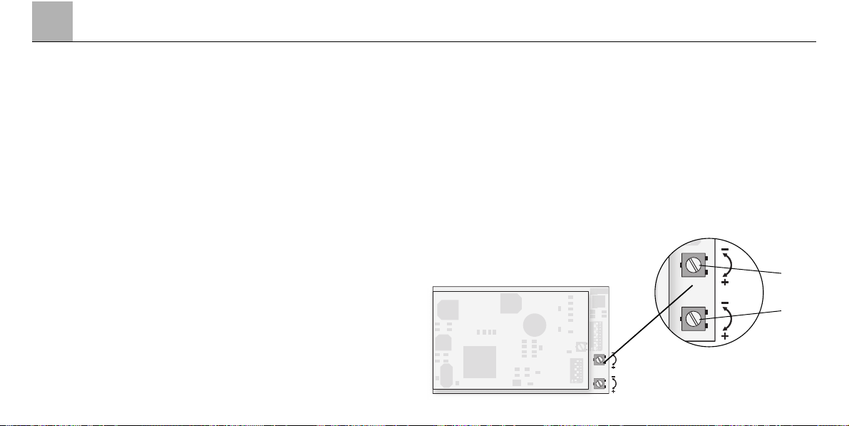
3.1 Anschluss der Gleisanlage
Um Spannungsverluste auf der Anlage zu vermeiden ist immer auf gutes
Zusammenpassen der Schienenverbindungslaschen zu achten. Alle
2 bis 3 m ist eine neue Stromeinspeisung über die Anschlussklemmen
5654 empfehlenswert.
3.2 Befahren von Steigungen
Im Gegensatz zum Vorbild können
mit einer Modellbahn auch größere
Steigungen befahren werden. Im
Normalfall sollte eine Steigung bei
maximal 3 Prozent liegen. Im Extremfall sind bei entsprechend eingeschränkter Zugleistung maximal
5 Prozent möglich. Der Anfang und
das Ende der Steigung sind auf jeden
Fall auszurunden. Der Unterschied
in der Steigung zwischen zwei mindestens 300 mm langen Gleisstücken
darf maximal 1 bis 1,5 Prozent
betragen.
3.1 Connections between the track
layout and the transformer
Rail joiners must fit well on the rails of
the track to which they are joined to
avoid voltage drop on the layout. We
recommend that you install feeder
wires every 2 to 3 meters (7 to 10 feet)
using the 5654 feeder clips.
3.2 Operating the locomotive
on grades
In contrast to the prototype a locomotive on a model railroad can operate
up steeper grades. As a general rule a
grade should be no steeper than 3%.
In extreme situations a maximum
grade of 5% is permissible, keeping in
mind that the locomo-tive’s tractive
effort will be less. The beginning and
the end of the grade must always work
gradually up to maximum grade for the
route. The maximum allowable difference in grade between two track sections, each with a minimum length of
300 mm (11-3/4") is 1 to 1.5 percent.
3.1 Connexion des voies ferrées
Pour éviter des pertes de potentiel
sur l’installation, il faut veiller à ce que
les éclisses de liaison des rails soient
tou-jours parfaitement adaptées. Une
nou-velle alimentation électrique est
conseillée tous les 2 à 3 m au moyen
des griffes d’alimentation 5654.
3.2 Franchissement des côtes
Contrairement à l’original, la maquette est également en mesure de franchir des côtes assez importantes.
En temps normal, une côte devrait
étre de l’ordre de 3% maximum.
A l’extrême limite, 5% sont envisageables avec une puis-sance du train
réduite en conséquence. Le début et
la fin de la côte doivent en tous cas
étre arrondis. La différence de pente
entre deux éléments de voie d’au
moins 300 mm de longueur doit étre
de 1 à 1,5% maximum.
3.1 Aansluiting van de sporen
Om spanningsverlies op de modelbaan te voorkomen moeten de raillassen altijd goed op elkaar aansluiten.
Om de 2 à 3 meter moet de voeding
opnieuw op de rails gezet worden.
Daarbij zijn de aansluitklemmen 5654
aan te raden.
3.2 Berijden van hellingen
In tegenstelling tot het grote voorbeeld kunnen met een modelbaan
ook grotere hellingen bereden worden. Normaal moet een helling maximaal 3 procent zijn. In extreme gevallen is maximaal 5 procent mogelijk,
maar dan moet reke-ning gehouden
worden met een even-redig verlies
aan vermogen. Het begin en het
einde van de helling moeten altijd
gerond worden. Het verschil in de
helling tussen twee tenminste
300 mm lange railstukken mag maximaal 1 à 1,5 procent bedragen.
3
41
3. Betrieb auf der Anlage Operation on a layout Exploitation sur réseau Bedrijf op een modelbaan
Page 41

42
4
Wartung Maintenance Entretien Onderhoud
4.1 Gehäuse abnehmen
• Entfernen Sie die vier Befestigungsschrauben an der Unterseite des
Modells.
• Nun kann das komplette Gehäuse
abgenommen werden.
Wichtig:
• Das Gehäuse nicht in der Höhe
der beiden Türen anfassen.
• Beim Aufsetzen des Gehäuses
unbedingt darauf achten, dass die
Glühlampen nicht durch die Trennwand im Gehäuse verbogen und
zerstört werden.
4.1 Removing the body
• Remove the four mounting screws
on the bottom of the model.
• Now the complete body can be
removed.
Important!
• Do not try to grasp the body in the
area of the two doors.
• When putting the body back on,
be careful that the light bulbs are
not bent and destroyed by the
partition wall in the body.
4.1 Enlever le carter
• Retirez les quatre vis de fixation
qui se trouvent sur la face inférieure de la maquette.
• Le carter entier peut à présent être
enlevé.
Important:
• Ne pas saisir le carter au niveau
des deux portes.
• Lors de l’installation de la caisse,
veiller impérativement à ce que les
ampoules à incandescence ne
soient pas tordues ou détruites
par la cloison située dans la caisse.
4.1 Huis afnemen
• Verwijder de vier bevestigingsschroeven aan de onderzijde van
het model.
• Nu kan het complete huis afgenomen worden.
Belangrijk!
• Het huis niet ter hoogte van de
twee deuren beetpakken.
• Bij het terugplaatsen van het huis
moet er onvoorwaasdelijk op gelet
worden dat de gloeilampen niet
door de scheidingswand in het huis
verbogen en beschadigt worden.
Page 42

4
43
Wartung Maintenance Entretien Onderhoud
Page 43

44
4
Wartung Maintenance Entretien Onderhoud
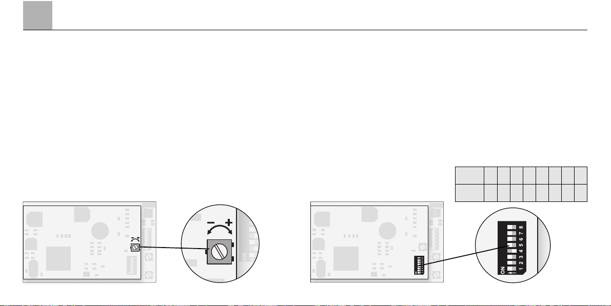
4.2 Schmierung nach 40 Betriebsstunden
Lubrication after 40 hours of operation
Graissage après 40 heures d’exploitation
Smeren na 40 bedrijfsuren
4.3 Glühlampen auswechseln
Changing light bulbs
Remplacement des ampoules à incandescence
Vervangen van de gloeilampen
600 080
592 200
Page 44

4
45
Wartung Maintenance Entretien Onderhoud
4.4 Haftreifen wechseln
Changing non skid-tires
Remplacement des bandages
adhérents
Nieuwe antislipbanden
omleggen
471 000
4.5 Schleifer wechseln
Changing pick-up shoes
Remplacement des frotteurs
Nieuwe sleepcontacten aanbrengen
544 120
Page 45

4.6 Kupplung austauschen
Beim Aufstellen der Lokomotive als
Vitrinenmodell kann die OriginalKlauenkupplung gegen eine Schraubenkupplung getauscht werden.
4.6 Changing couplers
The original claw coupler can be
exchanged for a reproduction prototype coupler when the locomotive is
to be put on display.
4.6 Remplacer l’attelage
Lorsque la locomotive doit servir de
marquette d’exposition, il est possible
de remplacer l’attelage automatique
d’origine par un attelage à vis.
4.6 Koppeling vervangen
Bij het opstellen van de lokomotief
als vitrinemodel kan de originele
klauwkoppeling door een schroefkoppeling vervangen worden.
46
4
Wartung Maintenance Entretien Onderhoud
Page 46

4
47
Wartung Maintenance Entretien Onderhoud
4.4 Pflegehinweis
Diese Lok kann auch im Außenbereich eingesetzt werden. Ein Betrieb bei
schlechten Witterungsbedingungen (Schnee oder Regen) wird nicht empfohlen.
Antrieb und Elektronik sind gegen Spritzwasser geschützt. Wasserdurchfahrten sind nicht möglich.
Es wird empfohlen, das Modell nach dem Betrieb im Außenbereich auf Verschmutzung zu prüfen und gegebenenfalls trocken mit Staubtuch oder Pinsel
zu reinigen. Nie die Lok unter fließendem Wasser reinigen.
Hinweis: Reinigungsmittel können die Farbgebung oder die Beschriftung der
Lok angreifen und beschädigen.
4.4 Tips For The Care Of Your Locomotive
This locomotive can also be used outdoors. We do not recommend running
the locomotive in bad weather (snow or rain). The mechanism and the electronic circuit are protected against spraying water. The locomotive cannot be
run through water.
We recommend that you check the locomotive over after running in outdoors
and that you dry it with a cloth or clean in with a brush if necessary. Never
clean the locomotive with running water.
Important: Cleaning fluids can attack the finish and lettering for the locomotive
and damage them.
4.4 Remarque sur l’entretien
Cette locomotive peut également être mise en service à l’air libre. Une utilisation par mauvais temps (neige ou pluie) n’est pas recommandée. Le moteur
et l’électronique sont protégés contre les projections d’eau. Des trajets dans
l’eau ne sont pas possibles.
Il est recommandé de vérifier l’encrassement du modèle après une utilisation à
l’extérieur et, le cas échéant, de nettoyer le modèle à l’aide d’un chiffon doux
ou un pinceau. Ne jamais nettoyer le modèle au jet d’eau.
Attention: Certains solvants et produits d’entretien peuvent altérer le marquage et la peinture du modèle.
4.4 Opmerkingen voor het onderhoud
Deze loc kan ook buiten gebruikt worden. Het gebruik bij slecht weer (sneeuw
of regen) is niet aan te raden. Aandrijving en elektronica zijn weliswaar afgeschermd tegen spatwater maar rijden door het water is niet mogelijk.
Het is aan te bevelen het model na het gebruik buiten te controleren op vuil
en dit eventueel droog te verwijderen met een stofdoek of een zachte kwast.
Nooit de loc onder stromend water reinigen.
Opmerking: reinigingsmiddelen kunnen de lak en de opschriften op de loc
aantasten en beschadigen.
Page 47

This device complies with Part 15 of the FCC Rules.
Operation is subject to the following two conditions:
(1) This device may not cause harmful interference, and
(2) this device must accept any interference received, including
interference that may cause undesired operation.
Gebr. Märklin & Cie. GmbH
Postfach 8 60
D-73008 Göppingen
www.maerklin.com
651 477 03 04 he na
Änderungen vorbehalten
 Loading...