

MyTrickRC UF7B User Manual

UF7B
Universal Hobby
Lighting Controller
Installation Instructions
for FW3.0
Please read instructions completely before attaching LEDs to RC.

Contents
LED INSTALLATION .....................................................................................3
POWER CONNECTIONS & SETTINGS .......................................................4
BLINK MODES ..............................................................................................5
MODE 0 ON/OFF .......................................................................................5
MODE 1 Watercraft ....................................................................................5
MODE 2 Basher/Crawler
MODE 3 Crawler (for Vehicles without Brakes) ......................................................6
MODE 4 Car 1 (Turn Signals normally OFF)...........................................................7
MODE 5 Car 2 (Turn Signals normally DIM) ...........................................................7
MODE 6 Drift (for Vehicles with Backre) ................................................................8
MODE 7 CHP/Police/Utility (Headlights normally OFF) .......................................9
MODE 8 Fire Truck/Police (Headlights normally ON) ........................................... 9
MODE 9 Aircraft 1 (with Landing Lights normally OFF) .......................................10
MODE 10 Aircraft 2 (with Landing Lights normally ON) ......................................... 11
MODE 11 Fighter Jet (with After Burner) ............................................................... 11
MODE 12 War Bird (with Slow WIG WAG Landing Lights) ....................................12
MODE 13 Trailer ........................................................................................13
TROUBLE SHOOTING ...............................................................................13
(for Vehicles with Brakes) .............................................5
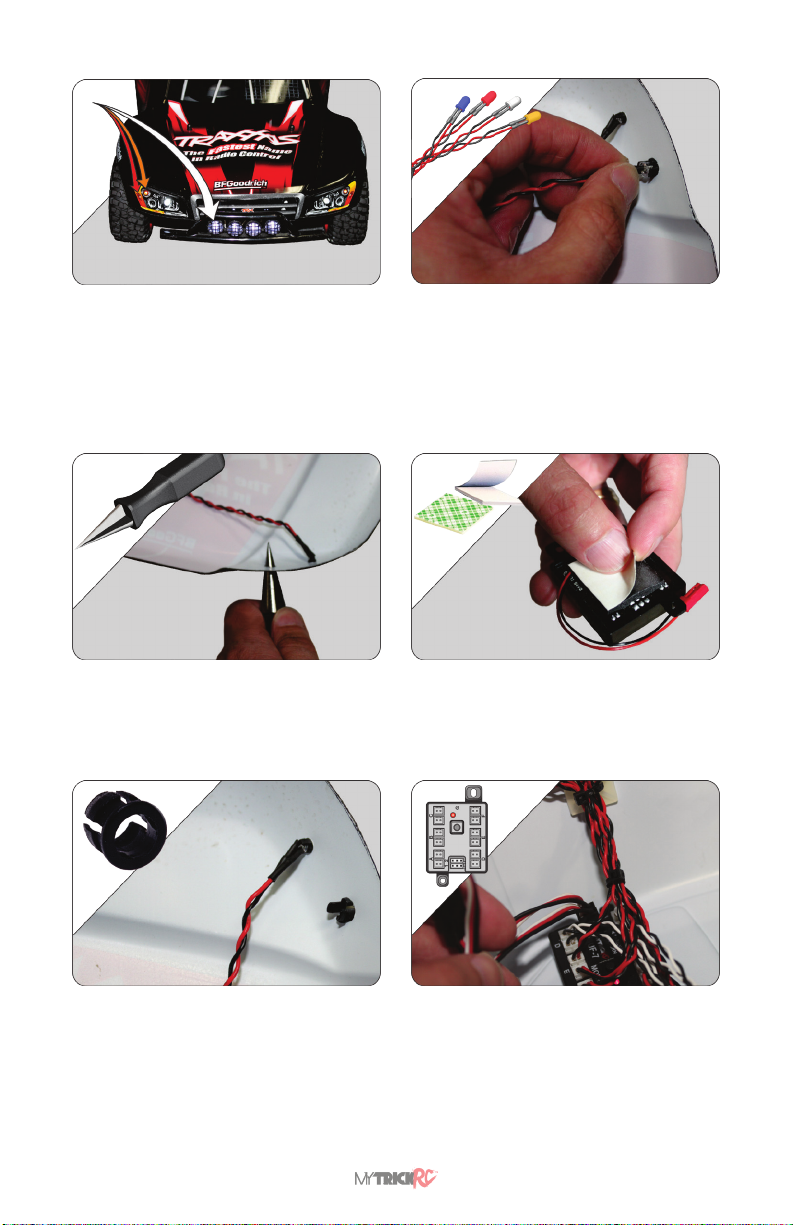
LED INSTALLATION
1. Choose where to install, what size, and
what color LEDs are to be used. Next, choose
the desired UF7B blink MODE (See Blink Mode
Section page 5).
NOTE – The blink MODE indicates
where to plug each LED into the UF7B
controller.
2. Drill Holes for LED Holders. Be careful
to not drill the hole too large. NOTE - You can
purchase a hand drill from your local RC hobby
store. Follow carefully all safety instructions
provided with the drill.
4. Insert LEDs into LED Holders. It is
recommended to apply a pliable glue, such as
Zap Goo or Shoe Goo, liberally making sure the
glue contacts the body, the LED and LED wires.
The glue should strengthen the wires and help
the LEDs last longer.
NOTE - The proper glue may be
purchased from an RC hobby store.
5. Attach UF7B Controller to vehicle using
it’s double back adhesive or using the breakaway
mounting tabs.
NOTE: The mounting tabs may be easily
twisted o if not used.
3. Snap LED Holders into Holes.
6. Connect LEDs to the UF7B Controller
NOTE: Connect each LED depending on the
desired blink MODE. See Blink Mode Section
on page 5. Example – For headlights, tail/brake
lights, and turn signals use MODE #6, Connect
HEADLIGHT LEDs to outputs A, D or E. Connect
TAIL LIGHTS to outputs B, connect RIGHT side
blinkers to output F, and LEFT side blinkers to
output C.
UF-7B Rev B3
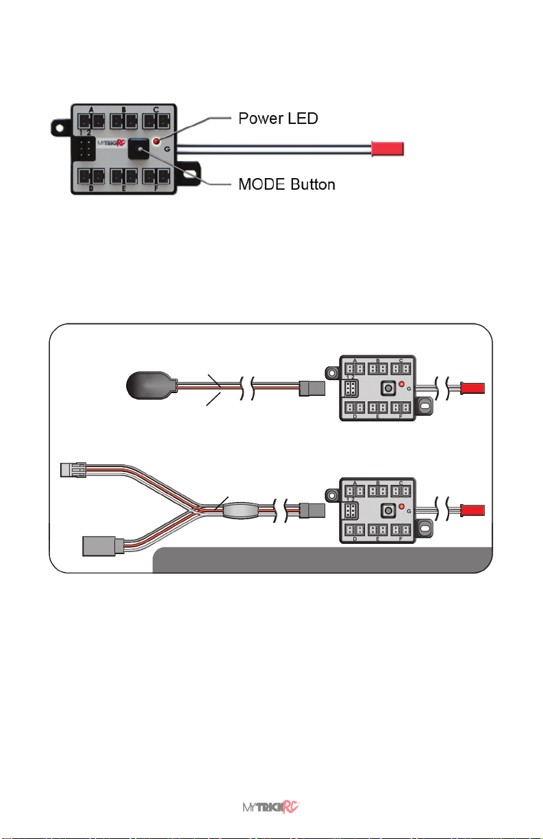
POWER CONNECTIONS & SETTINGS
Power Pass thru for
roof ashers or other
accessories.
NOTE: This is a power
OUTPUT not an input. DO
NOT connect to a battery.
9V Power Option – To power the UF7B using a 9V battery, plug the 9V Adapter cable into
either connector 1 or 2 as shown. If the power LED does not blink or turn on steady, press
the MODE button one time.
NOTE: MODE #0 (ALL OFF) does still draw a small amount to power.
9V ADAPTER
Connect to Port 1 or 2 as indicated in the Blink MODE
Black wire
Red wire
Y CABLE CONNECTION
Connect to Port 1 or 2 as indicated in the Blink MODE
Black wire
NOTE: Some modes require two ‘Y’ cables, not all packages
have two. You may require the deluxe version.
The UF7B has many dierent pre-programmed output MODES to t multiple lighting
requirements. Pressing the MODE button scrolls through the various modes. Once you
reach the last mode, the next button press sets the unit back to MODE #0 (OFF). When
power is applied to the UF7B the power LED will blink several times to indicate the software
revision of your controller. It will then blink to indicate the current mode.
Example: — • • • • • [pause] • • • • indicates Software Revision 1.5 [pause] Mode 4.
Each time you press the MODE button the power LED will blink the number of times
equivalent to the current MODE. For Example, 5 blinks indicates that the current mode is
#5. After blinking, the power LED will stay on steady to indicate power.
www.MyTrickRC.com 4
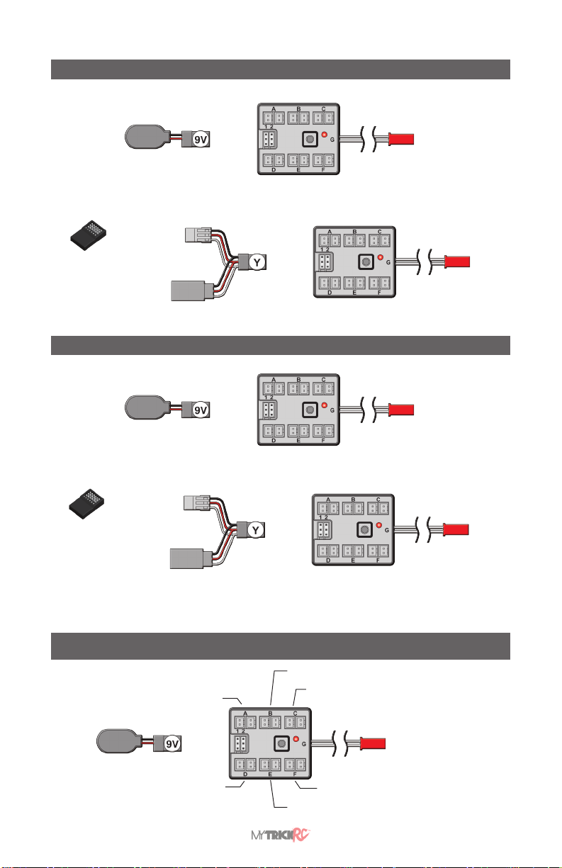
BLINK MODES
MODE 0 ON/OFF
PORT
1 or 2
OFF OFF OFF
OFF OFF OFF
OFF
AUXILIARY
POWER OUT
Connect to
Vehicle Radio
(3rd Channel)
(Not Connected)
Note: ON/OFF function on 3rd Channel (including Pig Tail)
Open
CHNL 1
No
function
CHNL 2
3rd
chanel
ON/OFF
control
OFF OFF OFF
OFF OFF OFF
OFF
AUXILIARY
POWER OUT
MODE 1 Watercraft
ON ON ON
ON
PORT
1 or 2
ON ON ON
Connect to
Vehicle Radio
(3rd Channel)
(Not Connected)
Note: 1. Hazard Lights (All LEDs turn o except ports B & D that blink as hazard lights after 20 sec). You can turn
OFF Hazard Lights by press-and-hold the Mode Button for 3 seconds. Repeat to turn back ON.
2. ON/OFF function on 3rd Channel (Ports A, B, C, and Pig Tail)
Open
CHNL 1
No
function
CHNL 2
3rd
chanel
ON/OFF
control
ON ON ON
ON ON ON
AUXILIARY
POWER OUT
ON
AUXILIARY
POWER OUT
MODE 2 Basher/Crawler (for Vehicles with Brakes)
Tail/Brake DIM
Reverse OFF
PORT
1 or 2
Running Lights DIM
Slow Blink (.5 sec ON then .5 sec OFF)
ON
AUXILIARY
POWER OUT
Center Brake Light OFF
Headlights ON
UF-7B Rev B5
 Loading...