

Mytrex RA3TX User Manual

Mytrex MXD Users Manual Rev 1
December 14, 2010
Users Manual for the
Mytrex Model MXD
Personal Emergency Response System
© 2010 All Rights Reserved
Manufactured by Mytrex, Inc.
10321 S. Beckstead Lane
South Jordan, Utah 84095
(801)571-4121, fax (801)571-4606
Toll free (800)688-9576 fax (877)571-4606
www.rescuealert.com
Notes: Multiple listings may be
requested for Rescue Alert and
VRI. Also, the name “Mytrex
Model MXD” may be replaced by
“Mytrex RA 500” and VRI’s model
1
may be named, “VRI 500.”

Mytrex MXD Users Manual Rev 1
December 14, 2010
Introduction
Congratulations! You have chosen the Mytrex MXD Personal Emergency Response System
(PERS) system, which you have obtained through the following service provider:
[Provider’s name
Provider’s address
Business Toll free number
Response Center Toll Free Number (if different from business number)
Fax Number
Email address
Web site]
The MXD has been created to provide you comfort, reassurance, and peace of mind by making it
possible for help to be just a touch of a button away.
Pressing your waterproof PHB will immediately activate the MXD PERS unit. Within seconds,
your response center will be notified of your need for assistance. When a call for help is
received, the response center’s computers provide an attendant with all of your personal
information. The attendant will talk to you through the MXD unit’s speakerphone. The
attendant will then telephone your family, friends, or emergency services based on the type of
assistance you need. Even if you cannot hear or speak to the attendant, help will be summoned
for you.
The MXD unit is fast and simple to install. Your service provider’s representative may connect
the MXD unit during an installation visit, you may elect to do it yourself, or you may ask a
friend or relative to install it for you.
To ensure that you always receive the fastest response time possible, it is very important that you
do the following:
Notify your service provider of any changes that should be made to your personal
account information. You can update your account by calling your service provider
or by pressing your PHB and relaying the information to the attendant over the
speakerphone. Your response center needs to be aware of changes to your address,
telephone number, responder information, medical history, allergies, doctor information,
hidden key location, and other information that you wish to have on file.
Test your MXD unit at least once a month by pressing your PHB.
Always wear your PHB!
2
Mytrex MXD Users Manual Rev 1
December 14, 2010
This User’s Manual has been designed to help you make the most of your MXD PERS system. If
you have any questions or concerns after reading this manual, please contact your service
provider.
MXD PERS Equipment Description
OVERVIEW
Your PERS system consists of the MXD base unit, telephone cord, and one or more Personal Help
Buttons (PHBs) or other accessories. The MXD unit incorporates several important features, including:
Compatible with Voice over IP (VoIP) telephone circuits in addition to standard telephone
technology
When enabled, interactive voice messages from the unit when the unit is calling the response
center and during certain setup operations
PHB detection ranges up to 600 feet from the base unit
Simplified base unit buttons and indicator lights
State of the art electronics
Capacity to remember many PHB and other device codes
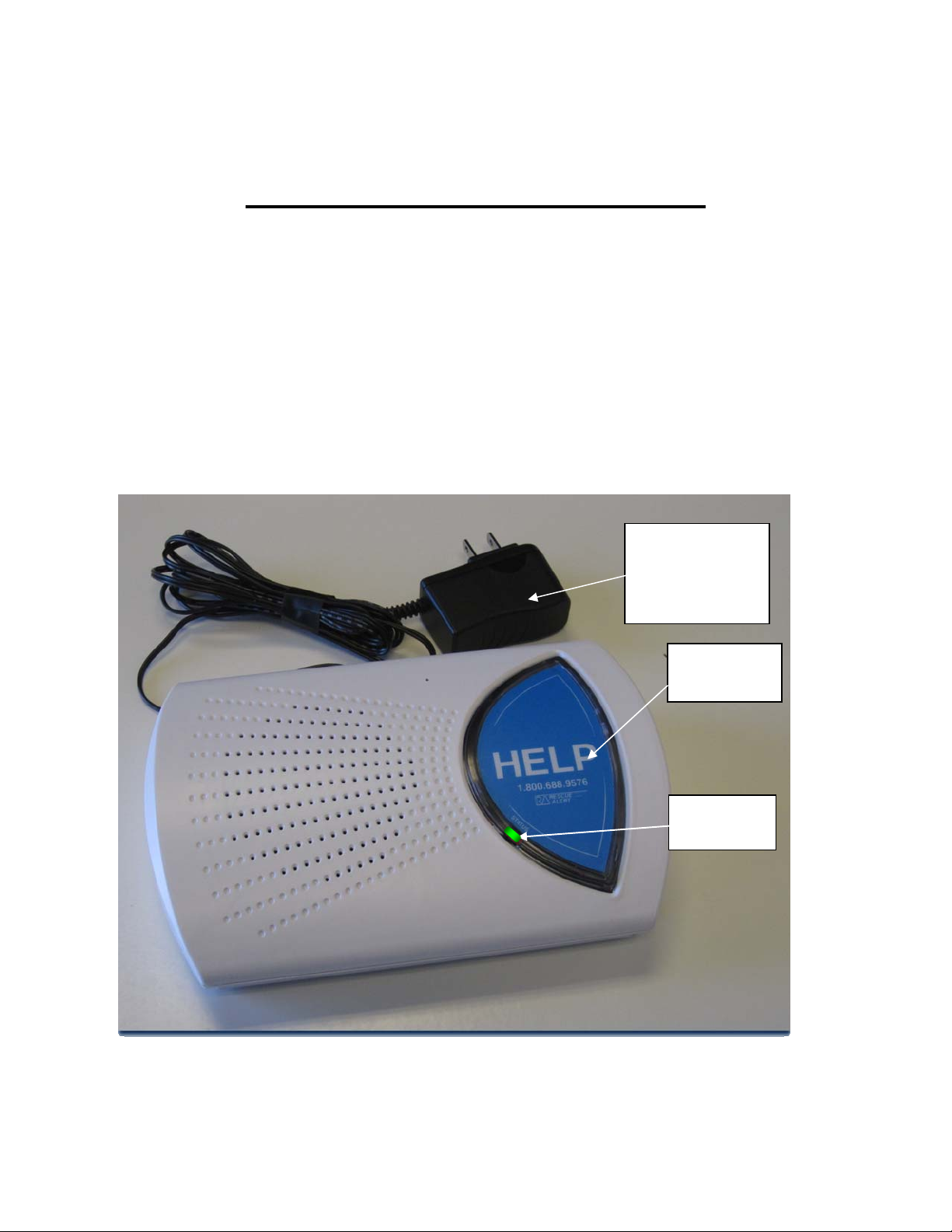
Power Block
and Cord (not
removable from
base unit)
Base Unit
Help Button
STATUS
Light
Figure1. MXD Base Unit and Power Cord
3
Mytrex MXD Users Manual Rev 1
December 14, 2010
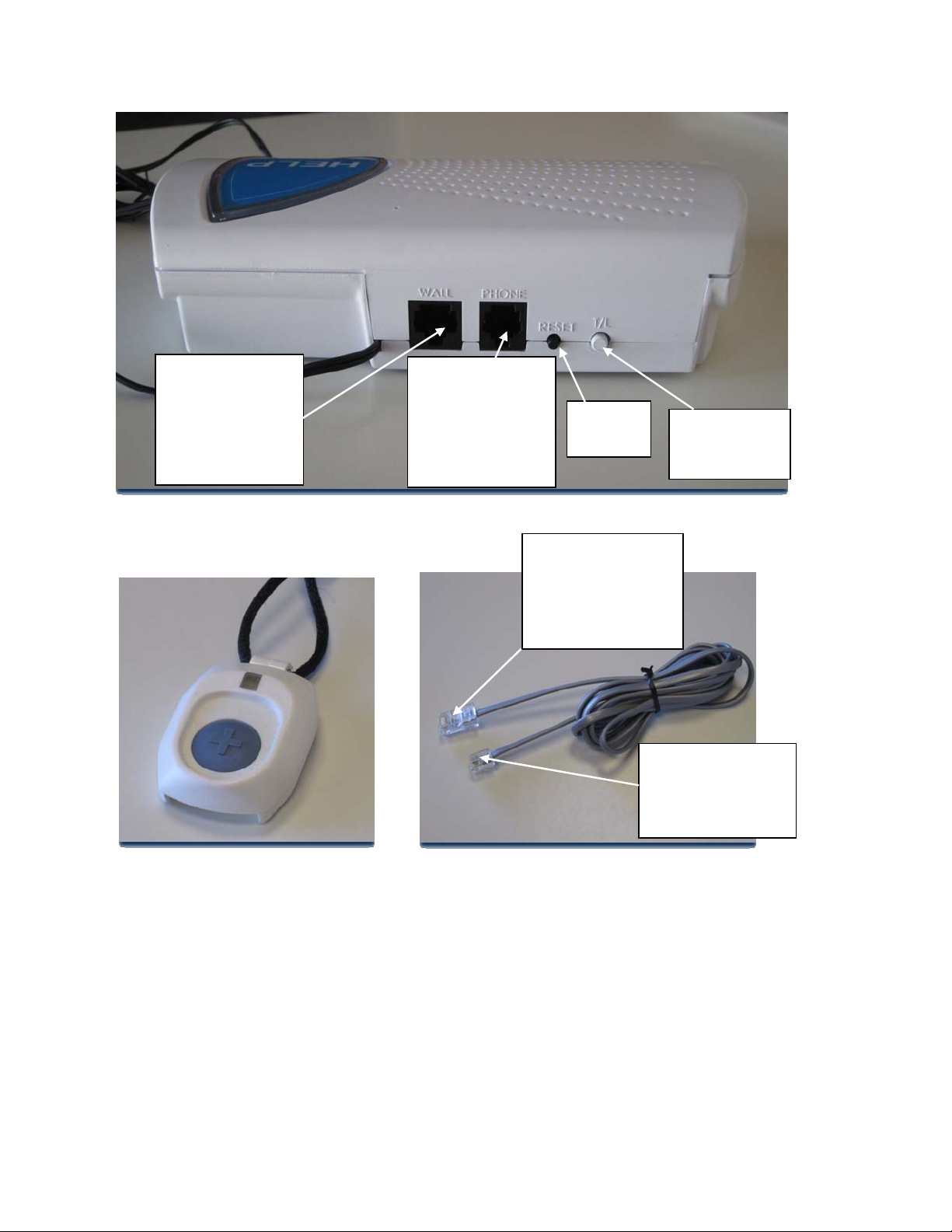
WALL (large)
Jack -- Insert
large end of
Rescue Alert
telephone cord
here
PHONE (small)
Jack -- Insert
your handset’s
telephone cord
plug here
Figure 2. Rear of MXD Base Unit
RESET
Button
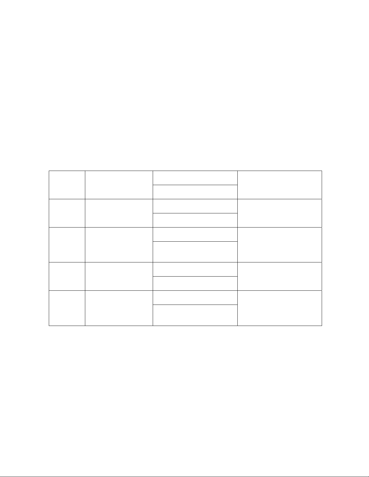
Plug the large
end into the
“Wall” jack on the
back of the base
unit
T/L
(Test/Learn)
Button
Plug the small
end into the
telephone jack
on the wall
Figure 3.
Personal Help Button (PHB) Figure 4. MXD Telephone Cord
Warning: Before your MXD system is ready for operation, it must be properly installed, have completed
a range test, and completed its first call to the response center. See the detailed setup instructions later in
this manual, or for additional information, contact your service provider.
BASE UNIT CONTROLS AND INDICATOR
The MXD base unit has three push buttons, including the large HELP button on the top of the base unit,
and two small buttons on the back of the unit that are used during initial installation and at other times if
needed. Each button is described below.
4
Mytrex MXD Users Manual Rev 1
December 14, 2010
Base Unit Help Button (Figure 1)
Normally, pushing the large blue Help Button on the front of your Rescue Alert base unit causes the unit
to send a “Help needed” message to the response center. The Help Button also is used with the T/L button
to conduct range tests and to program the MXD unit to recognize PHBs or other accessories.
STATUS Light (Figure 1)
A small STATUS light is located on the lower left edge of the unit’s large “Help” button. The STATUS
light will display steady or flashing lights, in either red, green or orange color, depending on the status of
the unit. See Page 15 for a more detailed description of the STATUS light signals and their meaning.
T/L (Test/Learn) Button (Figure 2)
The white T/L (Test/Learn) Button is located on the rear of your MXD unit. It is used to place your MXD
unit into special operating modes to conduct PHB range tests, to program PHBs and other accessories,
and to allow technical personnel to diagnose problems and adjust the unit.
T/L Operating Modes Chart
If the T/L
button is
pushed:
Once RANGE TEST
Twice MONITOR
Three times SERVICE
Four times Returned to normal
The base unit will be
placed in the following
mode:
mode
Voice Announcement (if
enabled)
Tone Signal (if voice not
enabled)
“Range Test Mode”
One brief tone
“Monitor Mode”
Two brief tones
“Service Mode”
Three brief tones
“System Ready”
Two quick tones in rapid
succession
The purpose of this mode is:
Test the range of the PHB and
search for areas where the PHB
signal is not detected by the
base unit
Allow a technician to listen
while the unit is dialing and
transferring data. This helps
the technician troubleshoot
problems.
Allows a response center
attendant to communicate with
the unit during troubleshooting
or re-programming
The unit is returned to its
normal mode, ready to process
alarm signals
RESET Button (Figure 2)
The black RESET button is located on the rear of your MXD unit. Whenever the RESET Button is
pressed, your MXD unit will return to its standard operating mode, ready to transmit alarms from the
PHB or the Base Unit Help Button if the unit is properly installed. The unit will sound two quick tones
when it is reset. If voice announcements are enabled the unit will announce, “System Ready.”
The RESET Button may also be used to cancel your call for help if your MXD unit is inadvertently
activated. To cancel a call for help, the RESET Button must be pressed within 10-15 seconds of
activation; otherwise, the unit will already be communicating with the response center. The response
center is staffed 24 hours a day, therefore, it is best to allow your MXD unit to complete the call and tell
the attendant that you accidentally activated your MXD unit.
5

Mytrex MXD Users Manual Rev 1
December 14, 2010
Personal Help Button (Figure 3)
Each MXD unit is supplied with one or more Personal Help Buttons (PHBs). The PHB is a small
waterproof pendant that may be worn around the neck on a breakaway cord, or may be worn attached to a
wrist band. When pressed, the PHB sends a “Help needed” radio signal to the MXD base unit, causing it
to call the monitoring center. Within a few seconds, an attendant will talk to you through your MXD base
unit’s speaker to determine if help is needed. The PHB transmitter and the base unit receiver are carefully
designed to ensure that the base unit can detect the PHB’s signal at distances of up to 600 feet away from
the base unit.
Setup Guide
Your MXD is designed to work with many different types of telephone technologies, including traditional
Plain Old Telephone Service (POTS), Voice over Internet Protocol (VoIP), cable company telephone
systems, and Digital Subscriber Line (DSL) service. This section provides instructions for setting up the
MXD to work with POTS, DSL, and VoIP telephone service. Telephone systems provided by cable
companies generally require connections similar to POTS telephones. Please contact your service
provider if none of the following setups work for your system.
Initial Setup steps for Any Type of System:
For any of the following setups:
1. Locate a live telephone jack with an electrical outlet nearby. The electrical outlet must
not be controlled by a light switch. Select a location where the MXD unit can be placed
on a flat, horizontal surface and where it will be located centrally, in a part of your home
that is used frequently. While it is recommended that the MXD be placed on a flat,
horizontal surface, it can be wall mounted if necessary. The MXD unit should be located
away from the immediate vicinity of mechanical noise sources, i.e. oxygen generators,
electrical equipment, and all appliances such as televisions or stereos.
2. If a telephone handset has not been plugged into the telephone jack and used recently,
plug a telephone handset into the jack and make a call using the handset to a working
telephone number. Confirm that the call goes through and that both parties can hear and
speak to one another.
3. Unplug the telephone handset cord from the wall jack.
System Setup for Locations with Plain Old Telephone Service (POTS)
Figure 5 is a general representation of a setup for locations connected to traditional telephone service.
6

Mytrex MXD Users Manual Rev 1
December 14, 2010
Figure 5. MXD Connections for Traditional (POTS) Telephone Service
1. Complete the installation steps common to all setups that are listed on Page 6.
2. Plug your telephone handset cord into the jack on the back of the MXD unit marked
“PHONE”. If your home is equipped with DSL service, see configurations on page
8.
3. Find the telephone cord that was shipped with your MXD unit, with a larger modular
plug on one end and a smaller modular plug on the other end. Plug the smaller end into
the wall jack, and the larger end into the jack on the back of the MXD unit marked
“WALL”.
NOTE: When your MXD unit calls the response center, the telephone and any
other device connected to the PHONE jack on the rear of your MXD unit will be
disconnected during the call. This means if this telephone is off hook, your MXD
unit can still contact the response center. If there are other extensions of the same
telephone number in your home that are off-hook when your MXD unit needs to
place a call, it will not be able to unless the local telephone company has installed an
RJ31X jack or devices called “Line Grabbers” are properly installed on each
telephone extension. The RJ31X jack allows the MXD unit to disconnect any
telephone in the house that may be in use. IF you elect to have an RJ31X installed,
contact your service provider and ask for an RJ31X telephone cord, Mytrex part
number RA400-RJ31X. If you elect to use Line Grabbers, contact your service
provider for ordering and installation instructions.
4. Plug the power transformer into an AC outlet. Verify that the outlet is not controlled by
a light switch.
5. The MXD unit will automatically turn on and announce, “System Ready.” The small
“status” light on the lower left edge of the unit’s large “Help” button will show a steady
green light. This indicates that the unit is connected properly to the telephone circuit
and AC power. If the telephone is connected improperly, the unit will announce, “Please
Check Telephone Connections.” Please see page 20 for information on the status light
combinations that will display if the unit is not connected properly to the telephone
system and electrical power, and for troubleshooting instructions.
7
 Loading...