

Page 1
Mytek FW DIO Card – User Manual
Mytek FW DIO Card
User Manual
ver. 1.2 / Nov 2010
© Mytek 2009
Page 2

Mytek FW DIO Card – User Manual
This manual may be updated
Download the newest version at:
http://www.mytekdigital.com/download_library/
For technical support, technical tips and support check:
http://www.mytekdigital.com
or contact Mytek tech support at:
highend@mytekdigital.com
or at:
tel. (646)-613 1822
fax.(212)-202 5331
Mytek Digital
211 Centre Street
New York NY 10013
USA
FireWire® is a trademark of Apple Computer, Inc.
Page 3

Mytek FW DIO Card – User Manual
Content
Content
Content..............................................................................3
Introduction......................................................................4
Before You Begin.............................................................4
Quick Start........................................................................5
Card Installation..............................................................6
Connecting Clock Signal Line......................................11
Input Connection...........................................................12
Signal Routing................................................................13
Card Firmware Update.................................................19
Mainboard Firmware Update......................................21
Specifications..................................................................25
www.mytekdigital.com Page: 3 / 25
Page 4

Mytek FW DIO Card – User Manual
Introduction
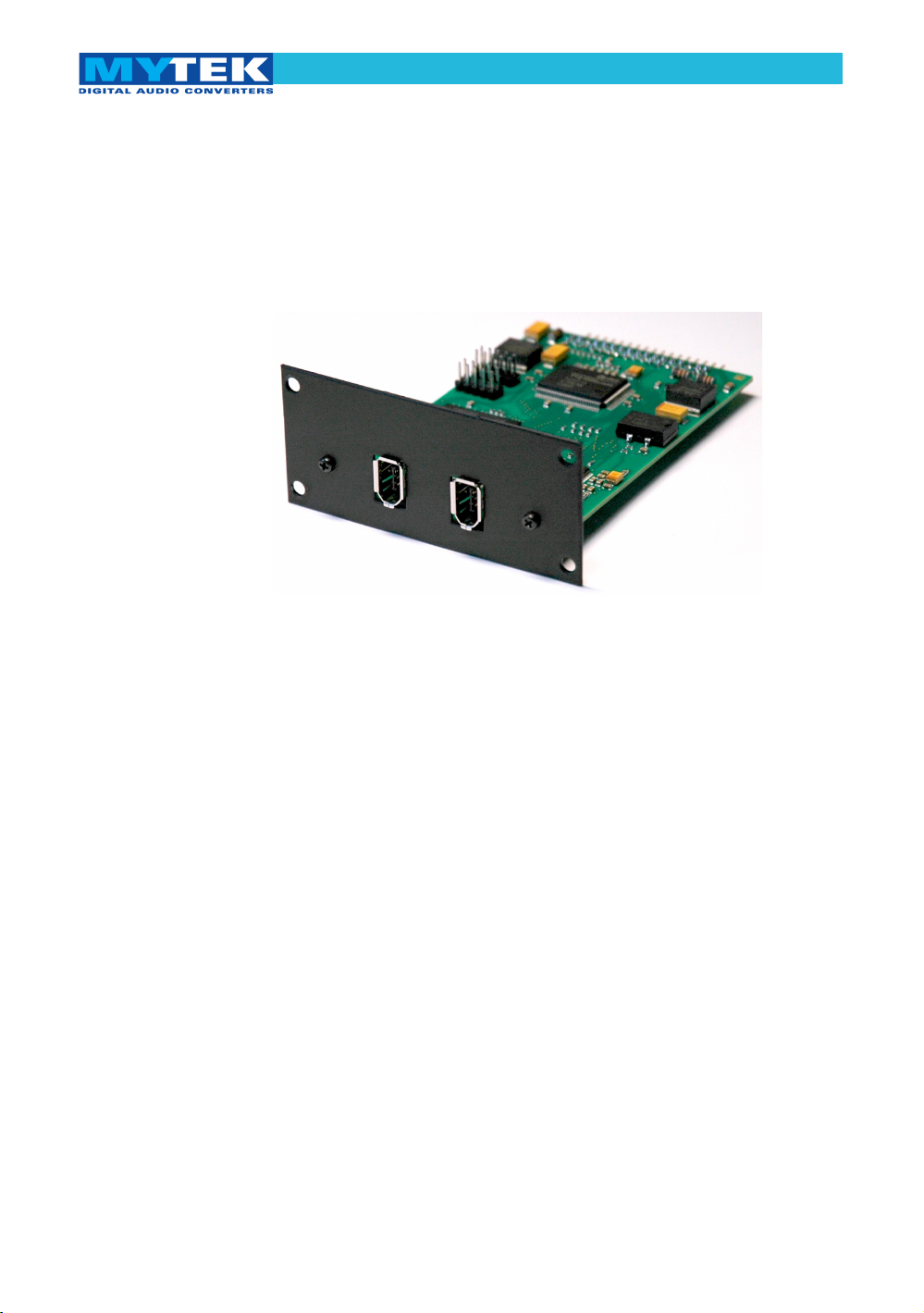
The Mytek FW DIO Card is an optional card that is installed
into the rear expansion slots of the Mytek 8X192 ADDA
converter. With this card installed the Mytek 8X192 ADDA can
be directly connected to a MAC OS or Windows computer via
FireWire. The card may be installed by the user as described
further in the manual.
Before You Begin
Before connecting the DIO-FW card please check if the most
current firmware (version 4.5.3 or later) is installed in the
8X192 converter. To verify the version, locate the firmware chip
(8 pin DIP chip in a socket near the aluminum heat sink) on the
main converter board or contact Mytek should you require
assistance.
In the support section of the Mytek website at:
http://www.mytekdigital.com/download_library/
you will find current detailed information about firmware
versions and most current firmware and driver update
instructions. (If necessary contact Mytek and request that
appropriate firmware be sent to you.)
www.mytekdigital.com Page: 4 / 25
Page 5

Mytek FW DIO Card – User Manual
Quick Start
1. Installation of DIO-FW card
Remove the top cover from the converter, unscrew the
DIOCARD1 or DIOCARD2 slot plate and install the DIOFW card using the existing screws in either slot. If there is a
Protools DIO card installed it will work in slot 1 only. All
other DIO cards including Firewire will work in either slot.
The card must be installed with the components facing
down. Double check that all connector pins match up with
the pins of the connector on the main converter board
properly. Pin mismatch may damage the card or converter.
Follow detailed installation instructions further below.
2. Driver Installation
Drivers and the Control Panel should be installed before the
first connection of the converter to the computer. Most
current drivers are available in the download library at
www.mytekdigital.com. Reboot the computer after
installation.
3. Connecting the card to the computer
Turn off the ADDA 8x192 converter before plugging in the
Firewire 400 cable. The computer can be left turned on.
Several converters can be chained together with Firewire
cables. The maximum number of converters in a chain
depends on the sampling frequency. Frequency 176–192
kHz allows for up to two converters, 88–96 kHz for up to
four converters and 44–48 kHz for up to eight converters.
After making the connections, the converter's can be
powered on.
3. Connecting the clock signal
A single or the first converter in the Firewire chain provides
clock source for the card. Typically it will be set to internal
clock, although if necessary, can be set to receive an
external wordclock source. If there are two or more
converters in a Firewire chain, they must be connected with
a Firewire cable where the first converter is a clock master
(on internal clock) and the rest are slaves (EXT. Clock
Source set to DIOCARD1 or 2 depending on FW card.)
Remember to turn off
and disconnect power
and to disconnect
signal cables while
working with the top
cover removed.
www.mytekdigital.com Page: 5 / 25
Page 6
Mytek FW DIO Card – User Manual
4. Configuration
On first power up of the converters, each converter should
be recognized by the computer and have the driver
installed automatically. Further configuration of inputs and
outputs is done in your DAW software.
In the Mytek Firewire Control Panel (Mac: in System
Preferences) check if the desired sampling frequency is
displayed and if the ADDA 8x192 converter is set as the
clock source. If more than one converter is attached, each
one will have unique name.
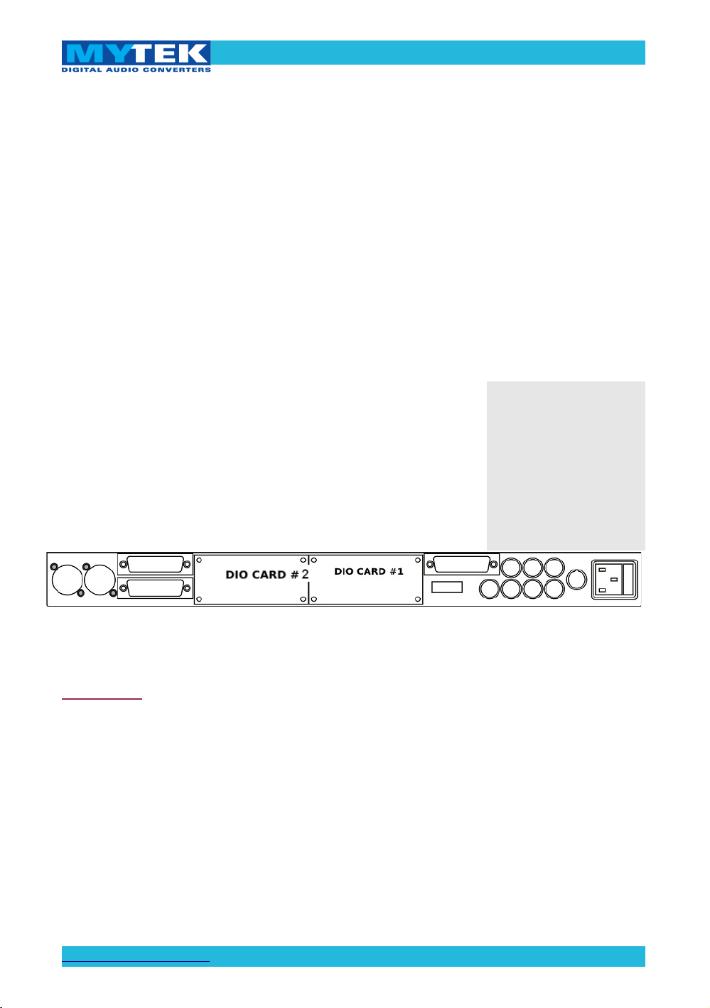
Card Installation
The DIO-FW card can be installed in either the DIOCARD1 or
DIOCARD2 slot. The card can be installed together with any
other card available for the 8x192 converter. If Protools DIO
card is installed it will work in slot 1 only. All other DIO cards
including Firewire will work in either slot.
8x192 ADDA converter rear panel
WARNING!
Remember to follow basic safety rules on electronic device
handling while opening the converter:
✔ Keep your hands dry,
✔ If floor is carpeted ground spray surroundings with
water mist and ground your wrist to the chassis before
unpacking and handling the DIO card.
✔ Turn off power and detach power and signal cables
while working with the top cover removed.
Before installing the
card, check if the
converter’s firmware
supports DIO-FW
card (version 4.5.3 or
later). If not, contact
Mytek and request
current version.
www.mytekdigital.com Page: 6 / 25
Page 7
Mytek FW DIO Card – User Manual
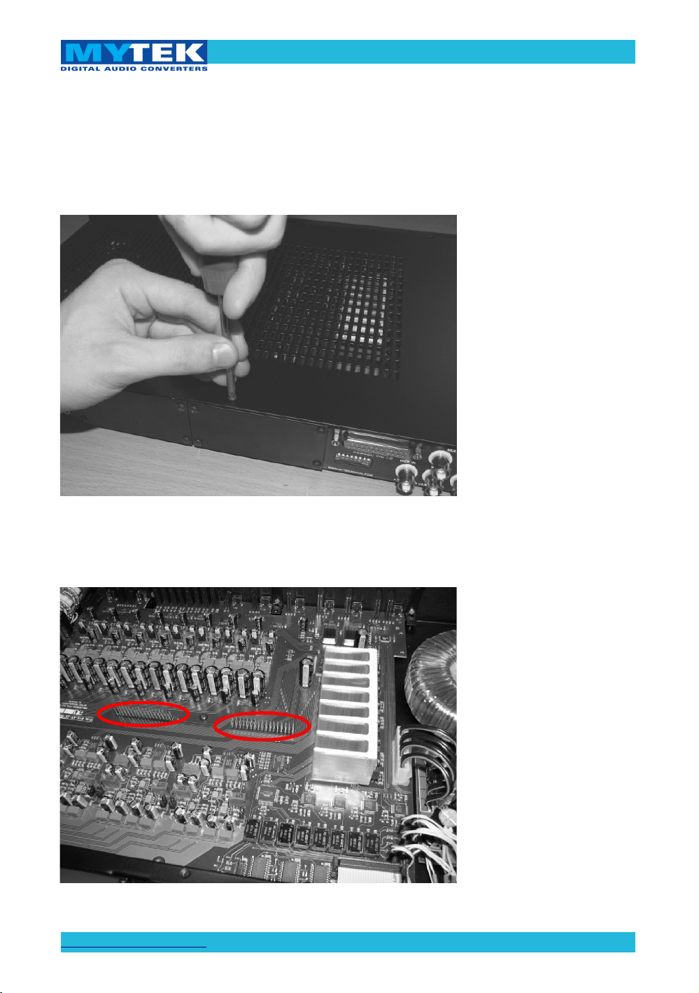
To install the DIO-FW card:
1. Check if the power cord and all signal and clock
lines are disconnected.
2. Remove the top cover.
3. Locate the DIOCARD1 or DIOCARD2 expansion
slot on the mainboard.
www.mytekdigital.com Page: 7 / 25
Page 8
Mytek FW DIO Card – User Manual
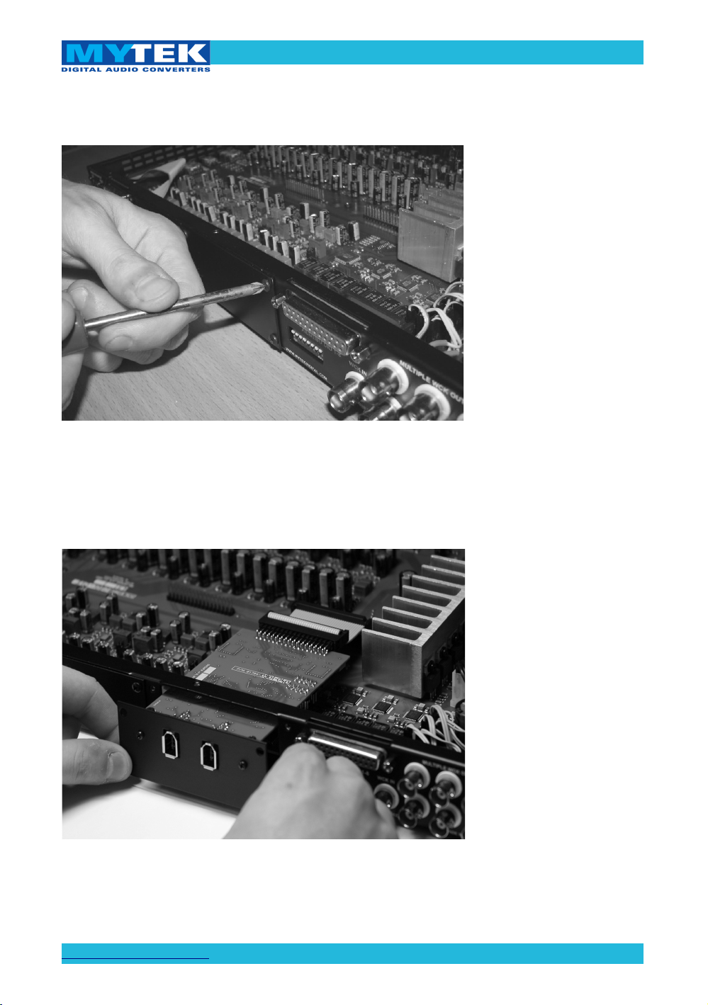
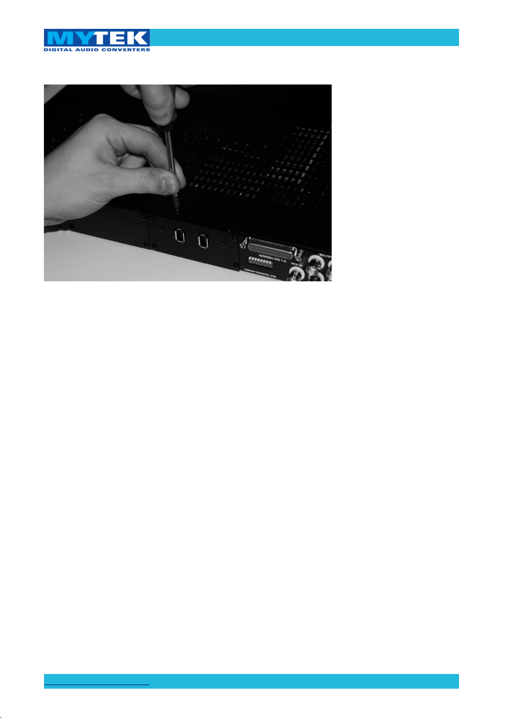
4. Unscrew the cover plate of the selected slot on the
rear panel.
5. Partially insert the card from the back of converter.
www.mytekdigital.com Page: 8 / 25
Page 9

Mytek FW DIO Card – User Manual
6. Connect the card ribbon cable to the DIOCARD1
connector on the mainboard. Double check all pin
alignment.
7. Gently push the card inside and secure it with four
screws
www.mytekdigital.com Page: 9 / 25
Page 10
Mytek FW DIO Card – User Manual
8. Attach converter top cover.
9. Connect power and signal lines.
10. Turn the converter on.
After boot up (which takes approx 20 sec) the converter will
switch to regular mode, and FW DIO Card (DIOCARD1 or
DIOCARD2) can now be selected as signal source for DAC.
Typically “analog” would be selected as ADC source (see
converter manual)
www.mytekdigital.com Page: 10 / 25
Page 11
Mytek FW DIO Card – User Manual
Connecting Clock Signal Line
Single converter
If a single converter is used in the system, using it's internal
clock will provide the best performance (regardless of what a
clock dealer will tell you.) If external clock is used for systemic
reasons SAMPLE RATE must be set to EXT. by pressing and
holding EXT CLOCK SOURCE switch.
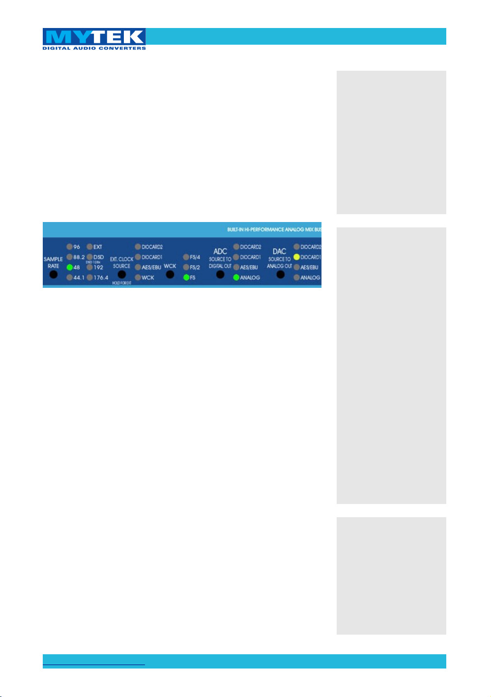
Master 8x192 ADDA converter front panel
Check if the selected sampling frequency of the converter (FS)
matches the sampling frequency in FW Control Panel.
Multiple converters/digital devices
The 8X192 ADDA converter has 6 clock outputs. Clock signal
originates from the very precise CX797 module. Because of that,
the 8X192 ADDA converter is the best clock signal source in the
majority of multiple device configurations. There is no reason to
attempt clocking 8X192 ADDA externally from a dedicated
clock generator. That clock, no matter how good, will always be
more jittery due to long cable run and thus cannot compete
with built in internal clock.
Our recommended setup when using the 8x192 ADDA with
additional 8x192's utilizing the FW DIO is to have the master
unit on Internal clock and the slave units (connected with
Firewire cable) set to Ext. Clock Source DIOCARD1 or
DIOCARD2 depending on location of the FW DIO card. All
other digital devices can receive wordclock from the 8x192's
multiple clock outputs.
In a system with
multiple units, double
check that the
configuration of clock
signal lines,
synchronization
sources and sampling
frequencies of all
converters in the
system are correct.
Correct clock
configuration is
necessary for the
proper operation of the
converters and for the
best sound quality.
Make the 1st Mytek in
the chain the clock
master for the whole
studio. There is no
benefit of using a
dedicated clock.
Clocking off the
Mytek's internal clock
generator produces
superior results
because the clock and
the clock line current
drivers are the best in
the industry.
Changing external
synchronization
source while the
program is running
may result in improper
operation of converters
and loud cracks in the
analog section.
www.mytekdigital.com Page: 11 / 25
Page 12
Mytek FW DIO Card – User Manual
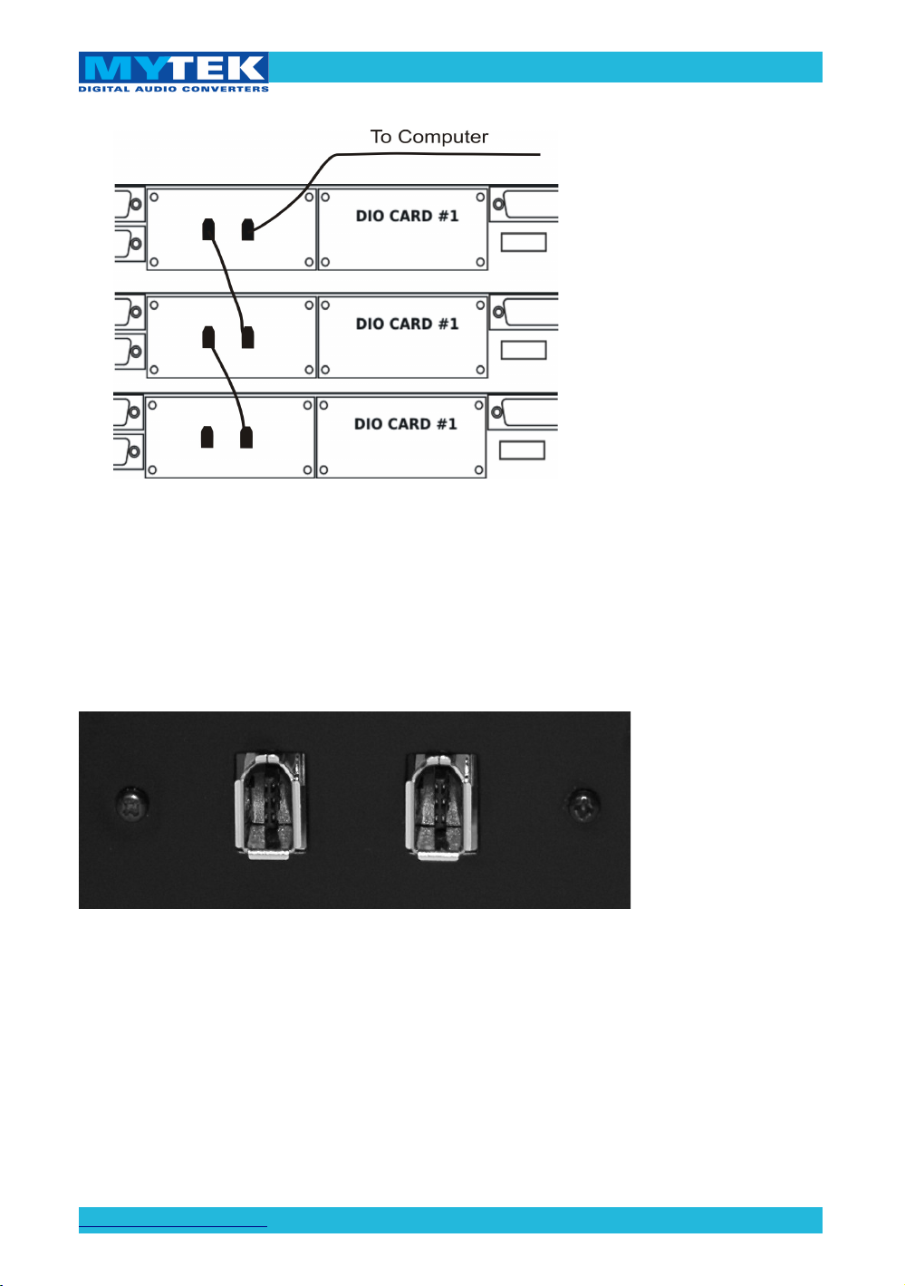
FireWire Chain
Input Connection
There are two FireWire ports on DIO-FW card. Either one can
be used for computer connection. The second port can be used
to daisy chain a second converter.
Firewire connectors on the back of FW-DIO card.
If several converters are connected, each must have a unique
name. When the converter is turned on for the first time, it
receives a name “8x192 ADDA”. In the case of multiple units
the name can then be changed in the driver control panel.
www.mytekdigital.com Page: 12 / 25
Page 13

Mytek FW DIO Card – User Manual
Signal Routing
Every connected ADDA8x192 converter provides the system
with 8 input and 8 output channels. All channels are detected as
a single Mytek interface. If more than two channels are used,
audio software which understands multichannel I/O must be
used. Channel routing is typically assigned in a dedicated
hardware control panel of the audio software application.
Mytek Driver Control Panel
The Control Panel controls the converter's operating
parameters. It will display all active devices in a chain
connected to a particular FireWire computer connector.
Control Panel with one converter attached
Device (converter) nickname is displayed and can be changed
in the Control Panel. In the case of multiple converters, each
should be given a unique name manually.
www.mytekdigital.com Page: 13 / 25
Page 14

Mytek FW DIO Card – User Manual
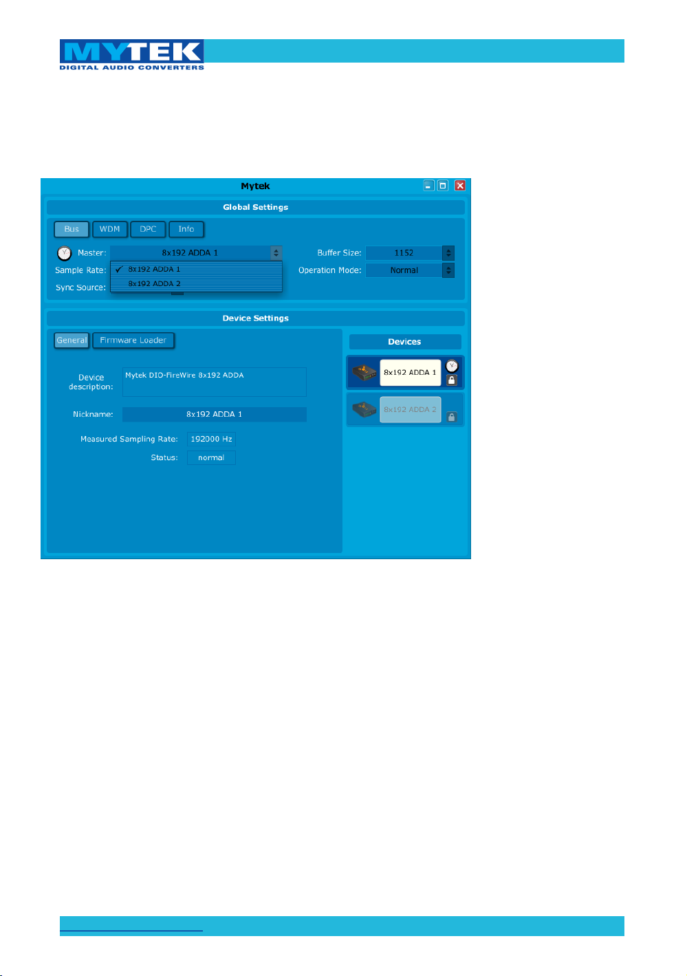
Select 8x192 ADDA as the sync source, set the sample rate in
the driver control panel to that currently used by audio
software. Changing sample rate in the control panel will force
the change on the converters front panel.
Selecting 8X192 ADDA as sync source
Selecting Sampling Rate
www.mytekdigital.com Page: 14 / 25
Page 15
Mytek FW DIO Card – User Manual
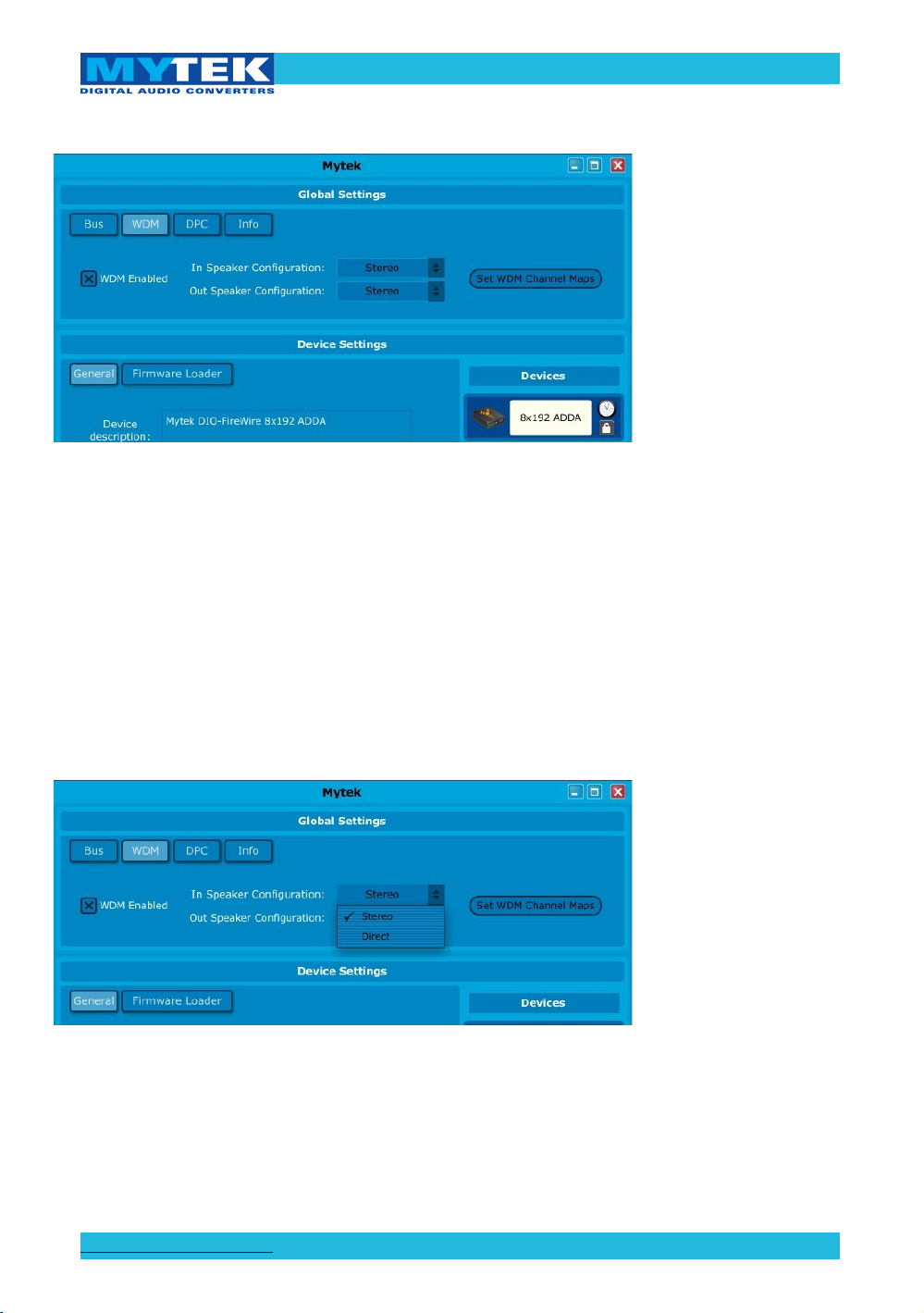
Windows version of the Control Panel allows user to choose
ASIO or WDM mode of operation. Generally start with WDM,
and experiment with ASIO later.
Mode selection screen
In the WDM mode operating channels can be mapped to
physical channels of the device.
Input channels offer two options: Stereo or Direct.
Input operating mode selection
In the output channel selection more options are available. They
include standard settings for the multichannel audio.
www.mytekdigital.com Page: 15 / 25
Page 16

Mytek FW DIO Card – User Manual
Output operating mode selection
You can now set how mode channels will be mapped to the
converter's physical channels.
Channel mapper
www.mytekdigital.com Page: 16 / 25
Page 17

Mytek FW DIO Card – User Manual
Feasibility of driver's operation modes depends on the
computing power at hand. If computer is too slow, dropouts
will occur in the audio signal. Typically shortages of computing
power are short and intermittent. Increasing data buffer size,
and therefore the latency, would usually result in dropout
reduction.
This function has been implemented in the driver under
different modes of operation: one normal mode and several
“safe modes”. Use the DPC tab to check computer latency and
suggested driver operation mode.
After measurements are completed and computer returns to its
normal operation, suggested driver operation mode should
appear.
Computer latency measurement.
If two or more converters are connected, each of them has to
have a unique name.
www.mytekdigital.com Page: 17 / 25
Page 18
Mytek FW DIO Card – User Manual
On the right side of the Control Panel there is a box which lists
converters and allows to choose the one which is about to be
configured. The one providing master clock is marked by a
clock icon.
Master clock selection
www.mytekdigital.com Page: 18 / 25
Page 19

Mytek FW DIO Card – User Manual
Card firmware update
To perform firmware update of DIO FW interface card:
1. Connect 8x192 ADDA converter to computer via
FireWire and turn it on.
2. Start Mytek control panel and press “Firmware
Loader” button.
3. Choose “Show details” box.
www.mytekdigital.com Page: 19 / 25
Page 20

Mytek FW DIO Card – User Manual
4. Browse for firmware update file.
5. Compare versions of firmwares. If browsed file version
is newer press “upload button”.
6. Wait until popup windows disappear
7. Restart 8x192 ADDA converter.
The firmware is now updated.
www.mytekdigital.com Page: 20 / 25
Page 21

Mytek FW DIO Card – User Manual
Mainboard firmware update
This update might be necessary to bring the converter's main
board up to date to allow its operation with the firewire card.
Generally installed main board firmware should be of rev. 4.5.3
or greater. Contact Mytek via email to obtain current firmware
chip.
WARNING!
Remember to follow basic safety rules about handling of
electronic device while opening the converter:
✔ keep your hands dry,
✔ remember to turn off power and disconnect power
and signal cables while working with the top cover
removed.
To perform firmware update of 8X192 ADDA converter:
1. Check if the power cord and signal and clock lines are
disconnected.
2. Remove the top cover.
www.mytekdigital.com Page: 21 / 25
Page 22

Mytek FW DIO Card – User Manual
3. Locate the memory socket on the converter main board.
4. Gently remove old memory chip.
To avoid damaging
memory pins, remove
the chip vertically.
Retain old memory
chip.
www.mytekdigital.com Page: 22 / 25
Page 23

Mytek FW DIO Card – User Manual
5. Carefully insert new memory chip in the socket. The
chip slot (pin1) should be matching the socket slot ie
must be facing back of the unit. If necessary gently
manually bend pins inward, to match the holes in the
slot.
6. Mount the top cover back.
During installation
check correct chip
orientation.
www.mytekdigital.com Page: 23 / 25
Page 24

Mytek FW DIO Card – User Manual
7. Attach power cord and other cabling.
8. Turn on the converter.
For about 2 seconds no LED should be lit on the converter’s
front panel, as new software is copied from memory to the
main board chips. Then, all LEDs should turn on momentarily
for about 10-20sec, and subsequently the unit should begin
normal operation.
Check Mytek webpage for information on the latest firmware
versions.
www.mytekdigital.com
www.mytekdigital.com Page: 24 / 25
Page 25

Mytek FW DIO Card – User Manual
Specifications
Latency – 512 Sample Buffer D/A/D Loop
OSX 10.6.5...............................................................~12ms
Windows 7 ASIO...................................................~10ms
A lower Sample Buffer
will result in lower
latency.
www.mytekdigital.com Page: 25 / 25
 Loading...