

Page 1
REVISIONS
REV.
DESCRIPTION
OD
ORIGINAL DRAFT
6
5
4
3
2
UNLESS OTHERWISE SPECIFIED:
NAME
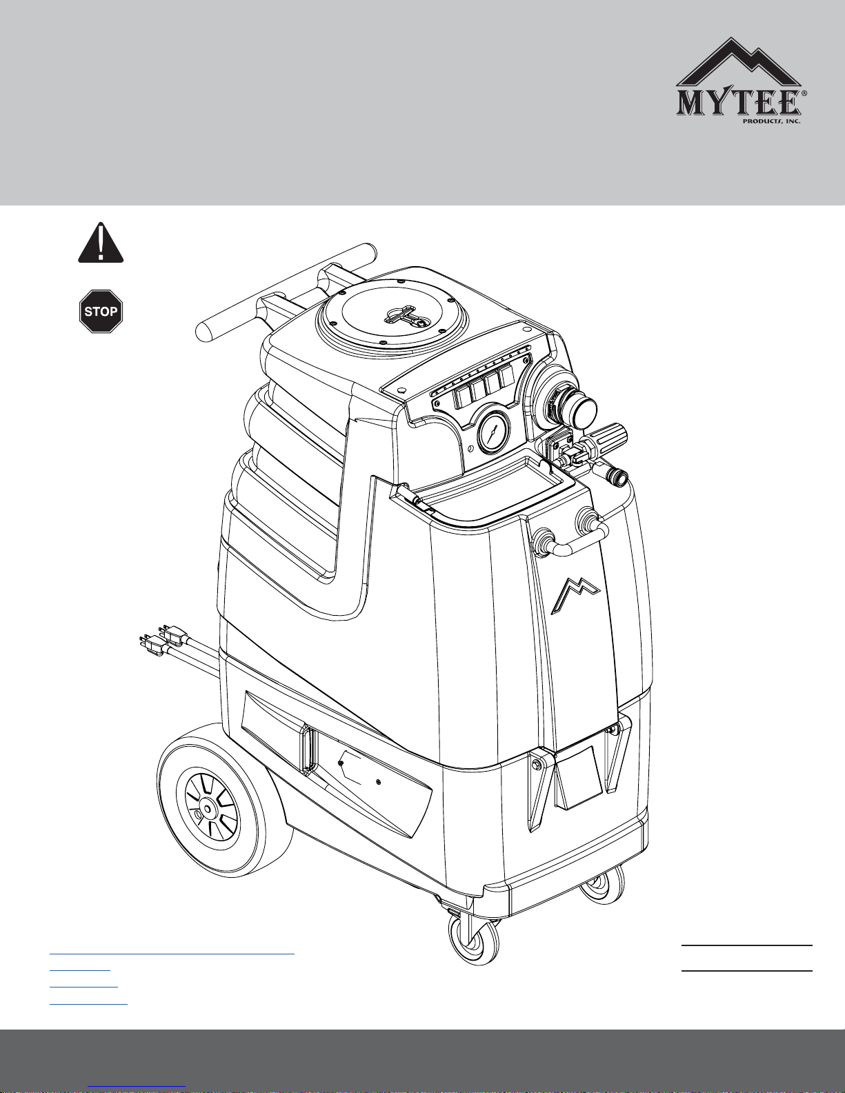
Instructions for
®
Speedster
LTD3, LTD5 & LTD12
Please read before use.
Register your product
at http://www.mytee.
com/support/register
General & Maintenance Information p. 2
LTD3 p. 6
LTD5 p. 13
LTD12 p. 20
13655 Stowe Dr., Poway, CA 92064
1
Model #
Serial #
Form # ADP-SLTD
9-17
Page 2

GENERAL INFORMATION
Dear Customer:
Congratulations on the purchase of your new LTD Speedster® extractor.
As technology continues to develop you can work condently knowing
that both Mytee Products Inc. and its employees are equally dedicated to
developing with the industry and its advances.
Like any other piece of machinery or technology, the LTDs also requires
the proper maintenance and care to keep the product working over
extended use. Neglecting your machine, abusing it or not operating it
properly can void its warranty and prevent the machine from performing to
the quality and standard you’d expect out of the Mytee Products Inc. line.
If you have any warranty concerns or questions, please review this manual
thoroughly or do not hesitate to contact your distributor. If there are questions regarding maintenance, replacement or ordering parts please contact
an authorized Mytee Products Inc. Service Center. To see an updated list
please visit our website at http://www.mytee.com/support/nd-distributors/
Before using your Mytee Product, please read this manually thoroughly.
Sincerely,
Mytee Customer Care Dept.
Grounding Instructions
This machine must be grounded. If it should malfunction or breakdown,
grounding provides a path of least resistance for electrical shock. This machine is equipped with a cord having an equipment-grounding conductor
and grounding plug. The plug must be plugged into an appropriate outlet
that is properly installed in accordance with all local code and ordinances.
Do not remove ground pin; if missing, replace plug before use.
Improper installation of the equipment-grounding conductor can result
in a risk of electric shock. Be sure to check with a qualied electrician
or service person if you are in doubt as to whether the outlet is properly
grounded. If the plug will not t in the outlet do not modify either the plug
nor the machine’s cord, instead have a proper outlet installed by a qualied technician.
This machine is for use on a nominal 120-volt circuit and with a grounding
plug similar to the one in Figure 1 below. If a proper outlet is not available,
follow the illustrations of Figure 2 & 3 to install a temporary-grounding
plug. This temporary work-around should be used only until a proper outlet
(Figure 1) can be installed by a qualied electrician. When and if this type
of adapter is employed, screw the adapter’s extended tab into place with
a metal screw. However, grounding adapters are not approved for use in
Canada.
Again, be sure to check the grounding pin for damages and replace if
necessary.
The Green, or Green-Yellow, wire in the cord is the grounding wire. When
replacing a plug, this wire must be attached to only the grounding pin.
DO NOT use extension cords.
Please Note for America use only
Grounding Pin
Figure 1
Grounded Outlet
Metal
Screw
Grounded Outlet Box
Figure 2 Figure 3
Adapter
Tab for Grounding
Screw
Parts and Service
Please contact a Mytee service personnel or Mytee authorized Service
Center using Mytee original replacement parts and accessories for repairs
are needing to be performed. When and if calling Mytee for support,
please have your Model and Serial Number available for faster assistance.
Name Plate
The Model and Serial Number are located on the lower half of the back
of the machine near the power plugs and will be required for ordering
replacement parts. You can use the space provided on the front of this
manual to note down both for future referencing.
Unpacking the Machine
1. When your new machine is delivered, please carefully inspect both the
shipping carton and the machine for damages. If damage is evident, save
both the shipping carton and machine so that the delivering carrier can
inspect it. Contact the carrier immediately to le a freight claim if there has
been any damage.
2. Install the Nylon-mesh pump-out pre-lter, packaged in the accessories
bag, into the interior base of the recovery tank. Slide the metal ring section
of the bag over the cylindrical main pump-out lter, such that the Nylon
bag covers the entire stainless steel mesh of the main pump-out lter.
Slide the ring to the base of the main lter. For identication, bag is shown
here.
Caution and Warnings
Symbols
Mytee uses the symbols below to signal potentially dangerous conditions.
Always read this information carefully and take the necessary steps to
protect personnel and property.
Is used to warn of immediate hazards that will cause severe personal
injury or death.
Is used to call attention to a situation that could cause severe personal
injury.
Is used to call attention to a situation that could cause minor personal
injury or damage to the machine or other property. When using an electrical appliance, basic precautions should always be followed, including the
following: Read all instructions before using this machine. This product is
intended for commercial use only.
To reduce the risk of re, electrical shock, or injury:
1. Read all instructions before using equipment.
2. Use only as described in this manual. Use only manufacturer’s recommended attachments.
3. Always unplug power cord from electrical outlet before attempting any
adjustments or repairs.
4. Do not unplug by pulling on cord. To unplug, grasp the plug, not the
2
Page 3
GENERAL INFORMATION
cord.
5. Do not pull or carry by cord. Do not close a door on cord or pull cord
around sharp edges or corners.
6. Do not run appliance over cord. Keep cord away from heated surfaces.
7. Do not use with damaged cord or plug. If cord is damaged, repair
immediately.
8. Do not use outdoors or on wet surfaces and or standing water.
9. Always unplug or disconnect the appliance from power supply when
not in use.
10. Do not allow to be used as a toy. Close attention is necessary when
used by or near children.
11. Do not use in areas where ammable or combustible material may
be present.
12. Do not leave the unit exposed to harsh weather elements. Temperatures below freezing may damage components and void warranty.
13. Use only the appropriate handles to move and lift unit. Do not use any
other parts of this machine for this purpose.
14. Keep hair, loose clothing, ngers, and all parts of the body away from
all openings and moving parts.
15. Use extra care when using on stairs.
16. To reduce the risk of re or electric shock, do not use this machine with
a solid-state speed control device.
17. The voltage and frequency indicated on the name plate must correspond to the wall receptacle supply voltage.
18. When cleaning and servicing the machine, local or national regulations
may apply to the safe disposal of liquids which may contain: chemicals,
grease, oil, acid, alkalines, or other dangerous liquids.
19. Do not leave operating unattended.
Preparation
1. Remove furniture and other items from the area you are going to clean.
2. Vacuum carpet and upholstery, and remove debris.
3. Protect cabinets, walls and painted surfaces with drop cloths or plastic.
4. Inspect power cords for damages.
Operating Instructions
1. Fill the solution tank.
2. Attach female end of a solution hose to a wand or other tool and the
male end to the LTD’s Quick Disconnect (QD).
3. Attach one end of a vacuum hose to a wand or other tool and the other
end to the LTD’s 2” Cuff-Lynx vacuum hose ports.
4. Plug in power cords:
power switches off to relieve any existing line pressure.
10. When the machine is off: unplug the power cables, remove solution
and vacuum hoses, and empty the recovery tank by attaching the 45º
drain elbow.
11. To empty the solution tank, twist off the solution tank drain cap located
on the back of the machine.
After Use
1. Before storing the machine, drain, rinse and dry both the tanks and
vacuum hoses of any residual water or solution.
2. Store standing upright in a dry, enclosed location.
3. Leave the recovery tank lid open for better air circulation.
4. If storing in freezing temperatures, take extra precautions to make sure
the machine and solution systems are completely drained and dry.
Maintenance Schedule
Latches are located in the back to open the tank for internal maintenance.
To keep machine in good working condition, follow the below recommended daily and weekly maintenance procedures. Relief valves should
be replaced annually.
Maintenance item Daily Once a week
Clean and inspect tanks.
Clean and inspect hoses.
Check and clean internal lters by twisting
off, rinsing with clean water and replacing.
Check power supply cable.
Clean machine with all-purpose cleaner
and cloth.
Check spray nozzles.
Flush solution system with Mytee® System
Maintainer.
Remove and oat shut-off screen from
tank and clean. Simply pull off.
Inspect vacuum hoses for holes and loose
cuffs.
Inspect spray pattern for clogging. If
clogged, remove spray tips and soak them
in a recommended liquid neutralizer for
up to six hours. To remove spray tip, twist
spray tip body counter-clockwise.
Lubricate wheels with water resistant oil.
Inspect machine for water leaks and loose
hardware.
x
x
x
x
x
x
x
x
x
x
x
x
LTD3/5/12 Model: Using two separate circuits/breakers, plug in the
grounded power cables as previously instructed using the appropriate
grounding techniques.
The LED light strip will illuminate and sound a tone when plugged into
separate circuits/breakers.
2. When the hoses are attached, turn on Pump-Out switch.
3. The Prime Valve and Pressure Regulator are located on the front right
side of the solution tank and should be primed prior to use. To prime the
pump turn the valve to the Prime position for 30 seconds, and then turn
horizontally to the Run position.
4. Pull your wand’s trigger to ensure water is running through the lines to
avoid damage to the Pump and Heating unit (LTD3).
5. (LTD3) The heater switch has three positions: Off (Middle); 1,000 watts
using 1 heater (Top); 600 watts & 1,600 watts using 2 heaters (Bottom)
If the water heater is to be used, prime system and turn it on to the desired
wattage and wait ve minutes for the water to reach temperature.
6. To clean, make two dry passes for every one wet pass while working away from the power cords. For optimal use or heavily soiled areas,
repeat wash steps in the opposite direction.
7. To prevent motor or internal damage, use a preferred foam control
solution in the recovery tank. Remember to check for build-up in both the
recovery and solution tanks! When using auto-ll, make sure the pump-out
is ON while in-use.
8. Empty the Recovery Tank whenever you need to rell solution. Attach
the 45º drain elbow to the drain spout located in the back and lift the dump
valve to empty the tank.
9. Squeeze the wand or tool’s trigger for ve seconds after turning the
Filter Maintenance
All LTD models have lters that need to be checked and cleaned after
each week of use. Regular lter maintenance is a simple way to extend
the life of your machines.
Pump-Out Filters
The pump-out lter is located on the inside bottom of the black vacuum
tank. It is recognizable by its cylindrical shape. To maintain lter:
1. Remove the 7” clear vacuum tank lid.
2. Reach in and remove the nylon mesh pre-lter that covers the main
cylindrical lter. Grasp the mesh, and pull straight up, easing the metal
ring upward, clearing the main lter. A ashlight may be needed to locate
the lter assembly.
3. Reach in and unthread the cylindrical lter by rotating it counter clock-
wise.
3. Once the lters are out, check for debris and damage. Rinse both the
pre-lter and the main lter of any debris or replace if damaged.
4. Place main lter back into vacuum tank by rotating it clockwise onto the
brass nipple.
5. Slide the ring on the pre-lter over the main lter, and push the ring to
the bottom of the tank, so that the entire mesh bag covers the main lter
screen.
Pump Filters
The pump is a half-circle shaped screen located on the inside bottom of
the blue solution tank. To maintain lter:
1. Open black solution tank lid.
3
Page 4
GENERAL INFORMATION
2. Reach into solution tank and rotate the dome-shaped lter from its
brass nipple by rotating it counter clockwise.
3. Check lter for any debris or damage to screen. Rinse lter of any
debris or replace if damaged.
4. Place new or cleaned lter back onto brass nipple by rotating it
clockwise.
Auto-Fill Solenoid Filter
The solenoid lter is located inside of the auto-ll solenoid, which is inside
the base of the machine. The lter will be connected to the auto-ll male
QD that extends from the back of the machine. To maintain the lter:
Required Tools:
7/8” Wrench or crescent wrench.
3/4” Wrench
1. Open the machine by undoing the rear latches and rocking the top of
the unit forward until it is resting on the ground and the internals of the
base are exposed.
2. Locate the solenoid attached to the rear auto-ll and pump-out plate.
3. Place the 7/8” wrench of crescent wrench on the rear part of the
solenoid closest to the inside of the auto-ll plate to help prevent rotation
during steps 4 & 6.
4. Use the 3/4” wrench to loosen the 3/4” plug on the front of the solenoid.
5. Remove the solenoid screen and check for any debris or damage to
screen. Rinse the screen of any debris or replace if damaged.
6. Replace the 3/4” brass plug and screen then you can continue use as
normal.
Troubleshooting
There is no power.
1. Plug power cord(s) in proper outlet(s).
2. If using two cords, make sure each is plugged into a separate circuit.
3. Check circuit breaker and reset if tripped. There should not be any
additional items in use on the same circuit as the machine and the outlet
must be a 20-amp circuit.
Pump does not work properly
1. Snap quick disconnects rmly together.
2. Check solution tank; may be empty.
3. Jets clogged, remove jet and ush clean.
4. Filters clogged, remove lters and rinse clean with water.
5. Heater is blocked; ush out with Mytee’s® System Maintainer.
6. If brass check valve is stuck, replace valve.
7. Check pump wire. May need to reconnect wire.
8. Switch plate may need to be replaced.
9. If pump motor brushes are worn, replace pump.
Speedster® LTD3 heater does not work properly
1. If sensor mounted on the heater has popped, reset sensor by pushing
in button.
2. Heating element may need to be replaced.
LTD3 Specications
Solution Tank 11 gallons (approx.)
Recovery Tank 11 gallons (approx.)
Vacuum Dual 3-stage low amp
CFM 200
Water Lift 130”
Max. Pump PSI 500
Pump GPM 1.5
Pump- Out GPM 3.3
Heater 1,600W - 210° max.
Power
Consumption
Machine Weight 145 lbs.
Machine
Dimensions
Power Cord Dual 50’ 12/3 ex tension cords
Cord 1: 20 amps @ 115V 60Hz
Cord 2: 20 amps @ 115V 60Hz
30” x 20” x 42”
LTD3 230V Conguration Information
Model Number LTD 3 -2 30
Power
Consumption
Cord 1: 10 amps @ 230V 60Hz/50Hz
Cord 2: 9 amps @ 230V 60Hz/50Hz
LTD5 Specications
Solution Tank 11 gallons (approx.)
Recovery Tank 11 gallons (approx.)
Vacuum Dual 3-stage high performance
CFM 230
Water Lift 144 ”
Max. Pump PSI 500
Pump GPM 1.5
Pump- Out GPM 3.3
Power
Consumption
Machine Weight 135 l bs.
Machine
Dimensions
Power Cord Dual 50’ 12/3 ex tension cords
Cord 1: 20 amps @ 115V 60Hz
Cord 2: 14 amps @ 115V 60Hz
28” x 18.5” x 39”
LTD5 230V Conguration Information
Model Number LTD 5 -2 30
Power
Consumption
Cord 1: 10 amps @ 230V 60Hz/50Hz
Cord 2: 7 amps @ 230V 60Hz/50Hz
Vacuum motor does not work properly
1. Check that hose is tightly connected.
2. Close drain hose valve completely.
3. Secure the vacuum tank tightly.
4. If water is coming out of the vacuum motor, use a low foaming
detergent.
5. Clean upholstery tool or oor wand jets.
4
Page 5
GENERAL INFORMATION
LTD12 Specications
Solution Tank 11 gallons (approx.)
Recovery Tank 11 gallons (approx.)
Vacuum Dual 3-stage low amp
CFM 200
Water Lift 130”
Max. Pump PSI 1,2 00
Pump GPM 2.4
Pump- Out GPM 3.3
Power
Consumption
Machine Weight 184 l bs.
Machine
Dimensions
Power Cord Dual 50’ 12/3 ex tension cords
LTD12 230V Conguration Information
Model Number LTD12-230
Power
Consumption
Cord 1: 20 amps @ 115V 60Hz
Cord 2: 15 amps @ 115V 50Hz
28” x 18.5” x 39”
Cord 1: 8 amps @ 230V 60Hz/50Hz
Cord 2: 6 amps @ 230V 60Hz/50Hz
FAQs
Q: What comes standard with Speedster® LTDs?
A: Two 50’ power cords, hose hanger with screws, two Cuff-Lynx™ Model
Numbers: H141 Reducer and H110 Coupler Swivel, pack of Piglets™ and
45˚ drain elbow.
Q: Does Mytee® recommend tools for this machine?
A: All upholstery tools and wands can be used with the Speedster® LTD
series.
Q: Is there anything I can do to increase the expected life of my machine?
A: Running the vacuum motors with the tank empty and lid off will allow
excess moisture in the vacs to dry off. You should also run Mytee’s®
System Maintainer through the system to keep the hoses, pump, and
heater clean and free of debris.
5
Page 6
SPEEDSTER® LTD3
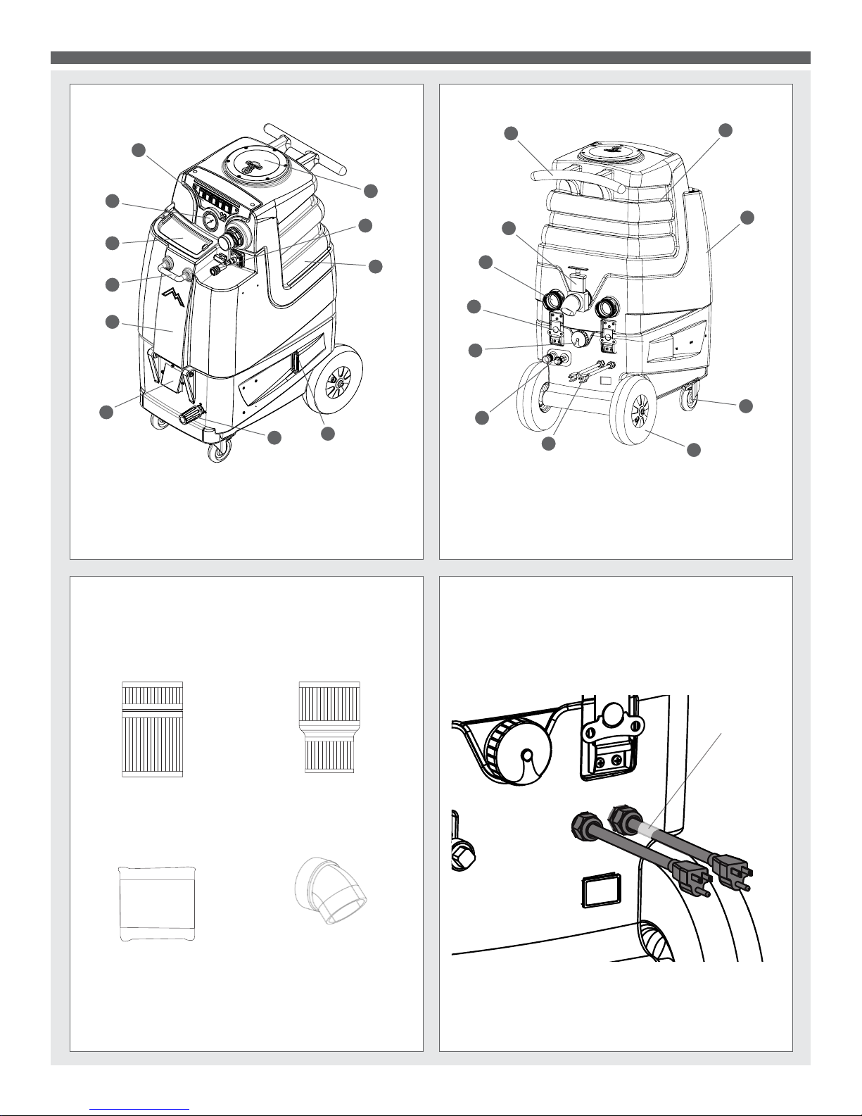
SPEEDSTER® LTD3 BACKSPEEDSTER® LTD3 FRONT
1
2
3
4
5
6
1. Switch Plate
2. Pressure Gauge
3. Solution Tank Lid
4. Front Handle
5. Solution Tank
6. Front Vent
11
10
9
7
7. Pressure Regulator
8. Side Vent
9. Recovery Tank
10. Solution Line Quick
11. Recovery Tank Lid
8
Disconnect
12
22
21
20
19
18
17
12. Push Handle
13. Recovery Tank
14. Solution Tank
15. 4” Locking Casters
16. 10” Foam Filled Wheels
17. Power Cords
13
14
15
16
18. Auto Fill/Pump-Out Hose
Connections
19. Solution Tank Drain
20. Service Latches
21. Rear Vacuum Exhaust
22. Recovery Tank Drain Valve
SPEEDSTER® LTD3 ITEMS INCLUDED
H110 Cuff-Lynx™
2” x 2” Hose Adapter
H141 Cuff-Lynx™
2” x 1.5” Hose Reducer
FILTERS
G008 Pack of Piglet™
lters
H226 Drain Elbow
POWER CORDS
(Primary) Right Cord: Plug in yellow-tagged power cable
for Power To Vac 1, Pump, & 600W Heater.
(Secondary) Left Cord: Plug in power cable for Vac 2,
Pump-Out & 1,000W Heater.
Yellow tag
indicates primary
cord.
Plug each power cord into a separate, 20A grounded wall outlet.
Outlets must be on two separate breakers. When the amber
light on the switch plate illuminates and the audible tone sounds,
the machine is on separate circuits (not necessarily 20A circuits).
You can identify the primary cord by the yellow tag.
6
Page 7
SPEEDSTER® LTD3
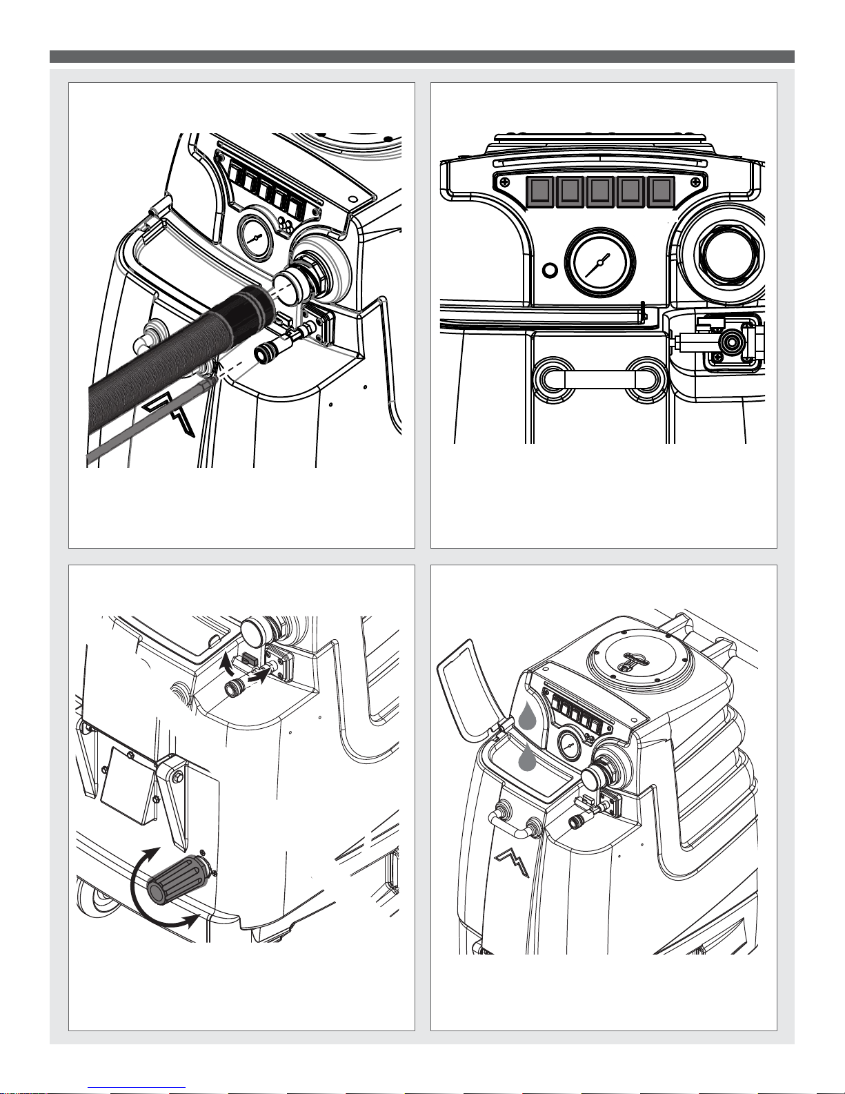
VACUUM AND SOLUTION HOSE CONNECTIONS
Attach female end of a solution hose to a wand or tool and the
male end to the LTD’s QD. Then connect a vacuum hose to a
wand and the 2” male Cuff-Lynx™ hose port. (If using the optional
de-foamer, install the kit onto the vacuum port according to the
instructions that come with the de-foamer kit.)
SWITCH PLATE
Vac 1 Vac 2 Pump
To use vacuum, turn on Vac 1 and Vac 2. To use pump, turn on
Pump. To use pump-out, turn on Pump-Out switch. To use Heater,
turn on Heater. Release tool trigger. Wait 8 – 10 minutes for unit
to pre-heat. Once heated, re-key upholstery tool until hot water
begins owing. Once hot water is owing, release trigger and
pre-heat an additional 4 – 5 minutes.
Pump
out
Heater
PRIME VALVE & PRESSURE REGULATOR
Prime the pump by having the Prime Valve parallel with its pipe
and turn it clock-wise to run the pump. Turning the Pressure Regulator to its left will decrease water pressure and turning to the right
will increase water pressure.
*Please refer to the Pressure Gauge to monitor your water pressure.
FILLING THE SOLUTION TANK
You can lift the lid to manually ll the tank or follow the “Operating
Instructions” for auto-ll use. IMPORTANT: Before relling solu-
tion tank, make sure the recovery tank is empty.
7
Page 8
SPEEDSTER® LTD3
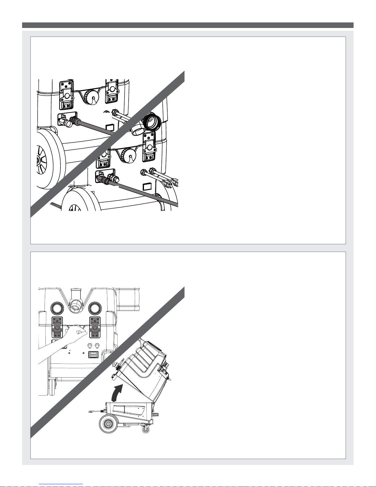
AUTO-FILL & PUMP-OUT CONECTIONS
AUTO-FILL
PUMP-OUT
Auto-ll: Connect standard garden hose from water source to LTD
auto-ll connection. Turn on the water source and let the tank begin
to ll. It will shut off when the water level reaches the oat switch in
the solution tank.
Pump-out: Connect a second standard garden hose to the LTD’s
pump-out connection and lay the other end of the hose in a drainable location. Activate the pump-out switch on the front of the
machine and open the ball valve on the pump-out connection. The
LTD will automatically drain recovered water from the tank.
OPENING THE MACHINE
To open the Speedster® LTD, loosen the rear latches by turning
them one quarter turn counter-clockwise. Flip the latches down
and then lift up on the push handle and the machine will open up.
8
Page 9

SPEEDSTER® LTD3
EMPTYING THE RECOVERY TANK
Make sure the Auto Pump-Out is turned off and then locate and lift
the bucket high drain valve on the rear of the LTD unit to empty
the tank.
SPEEDSTER® LTD3 SOLUTION TANK DRAIN VALVE
LOOSEN
TIGHTEN
To remove any remaining water in the solution tank, located
on the back of the unit is a cap, twist and remove cap to
empty tank.
FILTER MAINTENANCE
PUMP OUT
FILTER
INTAKE
REGULATOR
BY PASS FILTER
The LTD’s internal lters must be cleaned regularly and are located in the locations listed in the above diagram. Twist the lters
to remove them then clean and replace in original locations. If a
lter is torn or damaged, replace with a new one.
FILTER
MYTEE® SYSTEM MAINTAINER
Weekly ushing of the solution system with Mytee® System
Maintainer helps keep lines clean and prevents chemical build-up,
improving pump life, performance, and pressure.
9
Page 10

SPEEDSTER® LTD3 PARTS & PRICING
ITEMS NOT SHOWN
ITEM
NO.
PART NO.
DESCRIPTION
QTY.
MSRP
1
B160
adapter, brass, 1/2" barb x 3/8" fsw, ball end
3 $3.49 ea
2
B173
ferrule, 1/2", brass
8 $0.99 ea
3
PH615-37
sol hose, 1/2", 3045psi, black
1
$8.99 ft
4
H212
flat washer, 9/16"ID x 1 1/16"OD, AN960-C916
2 $0.99 ea
5
B199 coupler, 1/2" fpt x 1/4" fpt
3 $8.99 ea
6
B644
adapter, brass, 1/2" barb x 1/4" mpt
2 $2.49 ea
7
PH615-9
sol hose, 1/2", 3045psi, black
1
$8.99 ft
8
C381
pump out, 115v
1 $187.49 ea
9
H186
screw, 10-32 x 3/4, phil flat full thread
10 $0.99 ea
10
H210
washer, 1/4" flat, s/s
28 $0.99 ea
11
H273
nut, kep, #10-32 zinc
20 $0.99 ea
12
H109
wheel, 10", foam filled
2 $79.99 ea
13
H042
c-clip, 12mm, external
2 $0.99 ea
14
H232 axle, 19.60" x .50"
1 $9.99 ea
15
P514
vent, side, LTD
2 $5.00 ea
16
H668
caster, 4", black hub & gray tread
2 $19.49 ea
17
H342
bolt, 1/4-20 x 1" hex head, s/s 8 $0.99 ea
18
H216
nut, lock, 1/4-20, nylon insert, s/s
14 $0.99 ea
19
B103
elbow, brass, 90 deg, 1/4"mpt x 1/4" fpt 5 $4.49 ea
20
H044
bracket, regulator, panel mount
1 $27.99 ea
21
B127
plug, brass, 1/4"mpt, hex
1 $0.99 ea
22
C313C
regulator, 450 psi, silver spring
1 $86.99 ea
23
B136
elbow, brass, 90 deg, 1/4" mpt x 1/4" mpt
1 $4.99 ea
24
AH184 hose, 3/8" x 14-1/2" (OAL), f
1 $27.99 ea
25
PH634-23 sol hose, 1/4", silicone braided, clear
1
$6.49/ft
26
B170
ferrule, 1/4" brass
3 $0.99 ea
27
B152
elbow, brass, 90 deg, 1/4" barb x 1/4" mpt
1 $5.49 ea
28
B109
adapter, brass, 1/4" barb x 1/4" mpt
1 $1.99 ea
29
P511
LX series base
1 $196.99 ea
30
H202
bolt, 1/4x20x3/4" hex head
4 $0.99 ea
31
B652
elbow, brass, 90 deg, 3/8"mpt x 1/4"mpt
2 $8.49 ea
32
B259A
qd, brass, 1/4" fqd x fpt
3 $15.99 ea
33
B260A
qd, brass, 1/4" mqd x fpt
3 $8.99 ea
34
AH105
hose, pulse, 3/8" x 17-1/2"
2 $31.99 ea
35
B107 nipple, brass, 1/4"m, hex
7 $3.19 ea
36
B186
elbow, brass, 90 deg, 3/8"mpt x 3/8" fmpt
4 $8.99 ea
37
B105
bushing, brass, 3/8"mpt x 1/4" 3 $3.19 ea
38
PH615-8
sol hose, 1/2", silicone braided, clear
1
$8.99 ft
39
C313A
pump, CAT, 50-500 PSI, 120/240v
1 $599.99 ea
40
PH615-26
sol hose, 1/2", 3045psi, black
1
$8.99 ft
41
B123
adapter, brass, 1/2" barb x 1/4" fpt
1 $4.99 ea
42
H486
latch, front
2 $13.99 ea
43
H230
screw, 10-32 x 1/2" phil pan head, s/s 22 $0.99 ea
44
G068
bumper, 7/8" x 1/4" head 2 $1.99 ea
45
E564
controller, circuit light
1 $62.99 ea
46
H221
nut, lock, 1/2" steel
2 $1.99 ea
47
H220
fitting, strain relief, cord
2 $3.19 ea
48
E550
power cord, pigtail, 30", 12/3, black
2 $11.49 ea
49
E369
hour meter, panel mount, analog
1 $35.99 ea
50
B205B
QD, 1/2" npt x 3/4" mgh, pump-out
2 $3.99 ea
51
B204
qd, 3/4" female x female garden hose
2 $9.99 ea
52
B656A
ball valve, 1/2" m x 1/2" f 1 $16.49 ea
53
H039
plate, auto fill/ pump out
1 $9.99 ea
54
H231
screw, 10-32 x 1" phil pan head, s/s
2 $0.99 ea
55
H528
bracket, heater mounting, dual
1 $29.99 ea
56
AH156 hose, 3/8" x 6.5", (OAL), f x fsw, 5400 Gray
1 $23.99 ea
57
E571
heating rod, 600W, 115V
1 $49.99 ea
58
E574
Thermostat, 310°F ± 10°F, Manual, 1/4"
2 $17.99 ea
59
H274
screw, #6 x 3/16, phil pan head, self-tapping
10 $0.99 ea
60
E573
Thermostat, 200°, Auto, 1/4"
2 $16.49 ea
61
E519
heating rod, 1000W, 115V
1 $51.99 ea
62
H903A
heater, aluminum cast, single
2 $78.99 ea
63
B129
nipple, hex, 1/8" mpt x 1/8" mpt
2 $1.99 ea
64
H325
flow meter, electric truckmount
1 $189.99 ea
65
G069
gasket, flow meter
1 $0.99 ea
66
G036
cap, 2.5" threaded, tethered
2 $3.49 ea
ITEM
NO.
PART NO.
DESCRIPTION
QTY.
MSRP
67
B117
strainer, with check, chemical injector
1 $18.99 ea
68
PH634-26 sol hose, 1/4", silicone braided, clear
1 $6.49 ea
69
P535
bottle, 5 quart, w/ caps
1 $16.99 ea
70
H456B
cap (only) w/ hole
1 $3.99 ea
71
H547
hanger, wire for injection sprayer
1 $7.49 ea
72
B131
fitting, 1/4" barb x 1/8" FPT
2 $2.99 ea
73
PH634-18 sol hose, 1/4", silicone braided, clear
1 $6.49 ea
74
B143
street elbow, 90 degrees, 1/8"
2 $2.99 ea
75
H299
washer, 11/16"id x 1-1/2"od x .075, s/s
9 $0.99 ea
76
B216
nipple, brass, 3/8" x close
2 $1.99 ea
77
B210
bushing, brass, 1/2"mpt x 3/8" fpt, hex
2 $2.49 ea
78
B119A
filter, strainer, 1/2"
1 $6.49 ea
79
B119
filter, strainer, 1/4"
1 $3.99 ea
80
H254
washer, axle, cut 1/2" id
2 $0.99 ea
81
B110
adapter, brass, 1/4" sw barb x 1/4" fpt, w/gasket
1 $3.99 ea
82
H201
bolt, 1/4-20 x 1/2", hex head, zinc
2 $0.99 ea
83
H213
washer, 1/4" lock, s/s
8 $0.99 ea
84
H378
bracket, front hinge, sp/fb
1 $8.99 ea
85
H204
bolt, 1/4-20 x 1 3/4" hex head, s/s
2 $0.99 ea
86
H485
handle, aluminim grip, black
1 $6.99 ea
87
G052
washer, buna 1-1/8" od x 3/16" id
2 $1.99 ea
88
H211
washer, 1/4"id x 1"od, flat, s/s
2 $0.99 ea
89
H768
bolt, 1/4-20 x 3/4" serrated hex flange, zinc
2 $0.99 ea
90
P509
LX series sol tank
1 $141.95 ea
91
H650
bolt, 5/16" shoulder x 1-1/2" lg, alloy
1 $0.99 ea
92
P513
solution tank lid, LTD
1 $9.00 ea
93
H390A
bracket, "L"
2 $6.99 ea
94
H770
bolt, 1/4-20 x 1/2" serrated hex flange, zinc
4 $0.99 ea
95
H124
Cuff-Lynx, 2" mpt x 2" female cuff
2 $3.99 ea
96
H484
plate, mounting, QD
1 $4.99 ea
97
B142A
coupling, brass, 1/4" fpt x 1/4" fpt
1 $4.49 ea
98
B135
tee, brass, 1/4" mpt
1 $5.49 ea
99
B656
ball valve, 1/4'' 1 $13.49 ea
100
PH634-36 sol hose, 1/4", silicone braided, clear
1
$6.49 ft
101
B102
qd, brass, 1/4" f x 1/4" fpt
1 $17.99 ea
102
AH203
hose, pulse, 3/8" x 34"
1 $47.99 ea
103
H541A
valve, float, autofill
1 $108.99 ea
104
B198 adapter, 3/4" fgh x 1/2" mpt, w/ gasket
1 $16.99 ea
105
B167
street elbow, 1/2" fpt x 1/2" mpt
1 $10.99 ea
106
B303
nipple, 3" x 1/4" npt x 1/4" npt
2 $8.99 ea
107
B208
coupling, 3/8" fpt x 1/4" fpt
1 $8.99 ea
108
H541C
chemical injector
1 $39.99 ea
109
P512
LX series switchbox
1 $24.00 ea
110
E511
light, red, 250v
2 $5.99 ea
111
E516
switch, rocker, 3 position
1 $14.99 ea
112
AH120
sol hose, 28" x 1/4", 1/4 fpt
1 $35.99 ea
113
H308D
gauge, pressure, 2000psi
1 $38.99 ea
114
E515
switch, rocker, 2 position
4 $13.99 ea
115
H075
plate, switch, ltd3
1 $7.99 ea
116
E352
LED strip with lead wires
1 $26.99 ea
117
H031
plastite screw, 10 x 1"
2 $0.99 ea
118
H434
plug, vent, heyco, 1/2"
2 $4.48 ea
119
H135
Cuff-Lynx, 2" m cuff x 2" mpt
1 $3.99 ea
120
P510
LX series vac tank
1 $99.99 ea
121
H314
nut, lock, 1-1/2", steel
2 $1.99 ea
122
P520
adapter, pvc, 1-1/2" mpt x 1-1/2" fms
2 $2.99 ea
123
PH633-4
pipe, pvc, 1-1/2"
1
$4.99/ft
124
P503
adapter, 1.5" pvc, 45 deg, fslip x fslip
2 $3.29 ea
125
PH633-6
pipe, pvc, 1.5" 1
$4.99 ft
126
PH633-3
pipe, pvc, 1-1/2"
1
$4.99/ft
127
H343
screw, #10 x 5/8" hex head, zinc
6 $0.99 ea
128
H304
screw, #8 x 5/8 phil oval, s/s
6 $0.99 ea
129
G090 lid, vac tank, clear, 7"
1 $36.99 ea
130
G091
gasket, 7", vac lid
1 $11.99 ea
131
P755
elbow, U, 180, 1-1/2", float
2 $8.99 ea
132
H490
float, 2", ball style
2 $18.49 ea
ITEM
NO.
PART NO.
DESCRIPTION
QTY.
MSRP
133
PH633-13
pipe, pvc, 1-1/2"
1
$4.99/ft
134
A926
elbow, inlet assembly 2"
1 $15.99 ea
135
H226
spout, drain, 45 degree
1 $3.19 ea
136
H225
valve, drain, 1-1/2"
1 $20.99 ea
137
H333
mesh filter, auto dump, 1/2" npt
1 $12.99 ea
138
H503
vac support, 3 stage, 3.25", no thrds
6 $3.99 ea
139
G004
gasket, vacuum motor
2 $8.99 ea
140
PH628-7
vac hose, 2", black, wire reinforced
2
$8.99 ft
141
H217
clamp, hose, 2-1/4 dia
4 $1.49 ea
142
H194
coupler, 2" dia x 2.5" length, s/s
2 $10.00 ea
143
C302LA
vac motor, 3 stage, low amp
2 $139.99 ea
144
H096
bolt 1/4-20 x 4, s/s
6 $0.99 ea
145
B113
tee, brass, 1/4" fpt
1 $6.99 ea
146
B643 adapter, brass, 3/8" fnpt x 1/4" mnpt
1 $4.99 ea
147
B207
elbow, brass, 90 deg, 1/4" fpt x 1/4" fpt 1 $5.99 ea
PART NO.
DESCRIPTION
QTY
MSRP
E354
harness, electrical
1 $89.99 ea
E530
power cord, ext 50', 12/3, black
2 $74.99 ea
G008
piglet filter
1 $6.29 ea
G076
filter bag, 3.5" metal o-ring, mesh bag
1 $4.99 ea
H110
Cuff-Lynx, 2: hose x 2" fem swivel
1 $3.99 ea
H141
Cuff-Lynx, 2: x 1.5" reducer
1 $3.99 ea
H230
screw, 10-32 x 1/2" phil pan head, s/s 2 $0.99 ea
H375
hanger, wire formed, hose
1 $6.99 ea
P568A
cord lock, S-type
2 $8.99 ea
P590
cuties, 1/4" qd, standard pack of 2
1 $2.99 ea
D
C
B
A
A
B
C
D
1
2
3
4
5
6
7
8
8
7
6
5
4
3
2
1
E
F
E
F
LTD 3
SHEET 1 OF 3
speedster
SCALE: 1:32
REV
DWG. NO.
D
SIZE
TITLE:
NAME
DATE
CHECKED
DRAWN
PROPRIETARY AND CONFIDENTIAL
THE INFORMATION CONTAINED IN THIS
DRAWING IS THE SOLE PROPERTY OF
MYTEE PRODUCTS, INC. ANY
REPRODUCTION IN PART OR AS A WHOLE
WITHOUT THE WRITTEN PERMISSION OF
MYTEE PRODUCTS, INC. IS PROHIBITED.
mytee
PRODUCTS, INC.
858-679-1191
M.LaBarbera
10/2013
M
DO NOT SCALE
DRAWING
10
Part prices are subject to change.
Page 11

SPEEDSTER® LTD3 PARTS & PRICING
62
57
61
58
60
59
19
145
56
55
54
11
41
40
9
11
43
42
45
48
47
46
51
50
51
52
50
53
5
12
14
13
15
3
2
7
8
16
25
24
23
27
19
11
9
20
21
22
29
30
10
18
39
112
19
113
111
110
115
114
43
109
119
120
121
122
130
128
129
136
135
137
77
75
76
36
142
141
140
1
36
75
37
106
5
105
104
103
101
98
99
28
100
43
96
97
102
82
83
84
18
10
85
81
19
80
79
66
95
93
94
92
91
90
86
78
77
75
76
36
1
143
144
83
10
139
138
134
117
118
9
10
11
106
107
108
37
35
75
35
35
to garden
hose "OUT"
thru B656A
52
to vac tank
filter
thru
B186
36
to pump
"OUT"
thru B136
?
to sol
tank filter
thru B110
81
to lg sol
tank filter
thru B160
1
to heater
"IN" thru
B207
147
to pressure
gauge
thru AH120
112
to regulator
thru PH634
25
to garden
hose "IN"
thru PH615
40
to heater
"OUT"
thru B107
35
to pump
"OUT"
thru B107
35
tp pump-out
"IN"
thru B160
1
to regulator
thru AH184
24
to pump
"IN"
thru PH634
32
to float
thru B160
1
to garden
hose "IN"
thru B199
5
6
4
4
to pump-out
"OUT"
thru B199
5
5
44
49
124
132
133
147
to QD
thru AH203
102
35
146
35
35
33
32
31
38
6
32
33
37 36
34
33
32
31
35
2
17
10
18
66
67
68
69
70
71
43
72
73
74
63
65
64
to chemical
injector
thru H541C
108
26
33
26
116
1
87
88
89
131
125
123
126
127
to auto-fill
thru B107
35
D
C
B
A
A
B
C
D
1
2
3
4
5
6
7
8
8
7
6
5
4
3
2
1
E
F
E
F
LTD 3
SHEET 2 OF 3
speedster
SCALE: 1:32
REV
DWG. NO.
D
SIZE
TITLE:
NAME
DATE
CHECKED
DRAWN
PROPRIETARY AND CONFIDENTIAL
THE INFORMATION CONTAINED IN THIS
DRAWING IS THE SOLE PROPERTY OF
MYTEE PRODUCTS, INC. ANY
REPRODUCTION IN PART OR AS A WHOLE
WITHOUT THE WRITTEN PERMISSION OF
MYTEE PRODUCTS, INC. IS PROHIBITED.
mytee
PRODUCTS, INC.
858-679-1191
M.LaBarbera
10/2013
M
DO NOT SCALE
DRAWING
11
Page 12

SPEEDSTER® LTD3 WIRING DIAGRAM
L1
L2
G
L1
L2
G
VAC 1
L2L1
G
VAC 2
L2L1
G
E-516
Pump
Out
L2L1
G
Pump
L2L1
G
Hour Meter
1000 Watt Heat
600 Watt Heat
600 Watt 1000 Watt
G
G
C-302LA
C-302LA
C-313A
C-381
E-519
E-571
Secondary Cord
Primary Cord
E-515
E-515
E-515
E-515
E-564
L2a
L1b
L1a
L2b
light
3/31/2016
LTD3
115 Volt System
12
Page 13

REVISIONS
REV.
DESCRIPTION
DATE
APPROVED
OD
ORIGINAL DRAFT
JFL
D
C
B
7
6
5
4
3
2
1
E
F
11/2013
UNLESS OTHERWISE SPECIFIED:
NAME
DATE
DRAWN
DIMENSIONS ARE IN INCHES
TOLERANCES:
858-679-1191
mytee
PRODUCTS, INC.
V. LaBarbera
SPEEDSTER® LTD5
SPEEDSTER® LTD5 FRONT
12
11
10
1. Switch Plate
2. PSI Gauge
3. 2” Male Cuff-Lynx™ Inlet
4. Pressure Regulator
5. Prime Value
6. Female Quick Disconnect
7. Front Handle
1
2
3
4
8. Solution Tank
9. Front Vent
10. 4” Locking Casters
11. Solution Lid
12. Recovery Lid
SPEEDSTER® LTD5 BACK
13
14
5
6
7
8
9
22
21
20
13. Push Handle
14. Recovery Tank
15. Recovery Tank Drain Valve
16. Rear Vacuum Exhaust
20. Auto Fill & Pump-Out Hose
Connections
21. Solution Tank Drain
22. Side Vent
17. Service Latches
18. Power Cords
19. 10” Foam Filled Wheels
15
16
17
18
19
SPEEDSTER® LTD5 ITEMS INCLUDED
POWER CORDS
(Primary) Right Cord: Plug in yellow-tagged power cable
for Power To Vac 1, & Pump.
(Secondary) Left Cord: Plug in power cable for
Vac 2 and the Pump-Out.
H110 Cuff-Lynx™
2” x 2” Hose Adapter
H141 Cuff-Lynx™
2” x 1.5” Hose Reducer
Yellow tag
indicates primary
cord.
FILTERS
G008 Pack of Piglet™
lters
H226 Drain Elbow
Plug each power cord into a separate, 20A grounded wall outlet.
Outlets must be on two separate breakers. When the amber
light on the switch plate illuminates, the machine is on separate
circuits (not necessarily 20A circuits). You can identify the primary
cord by the yellow tag.
13
Page 14

SPEEDSTER® LTD5
VACUUM AND SOLUTION HOSE CONNECTIONS
Attach female end of a solution hose to a wand or tool and the
male end to the LTD’s QD. Then connect a vacuum hose to a
wand and the 2” male Cuff-Lynx™ hose port. (If using the optional
de-foamer, install the kit onto the vacuum port according to the
instructions that come with the de-foamer kit.)
SWITCH PLATE
Vac 1 Vac 2 Pump Pump
out
To use vacuum, turn on Vac 1 and Vac 2. To use pump, turn on
Pump. To use pump-out, turn on Pump-Out switch.
PRIME VALVE & PRESSURE REGULATOR
Prime the pump by having the Prime Valve parallel with its pipe
and turn it clock-wise to run the pump. Turning the Pressure Regulator to its left will decrease water pressure and turning to the right
will increase water pressure.
*Please refer to the Pressure Gauge to monitor your water pressure.
FILLING THE SOLUTION TANK
You can lift the lid to manually ll the tank or follow the “Operating
Instructions” for auto-ll use. IMPORTANT: Before relling solu-
tion tank, make sure the recovery tank is empty.
14
Page 15

SPEEDSTER® LTD5
AUTO-FILL & PUMP-OUT CONECTIONS
AUTO-FILL
PUMP-OUT
Auto-ll: Connect standard garden hose from water source to
LTD auto-ll connection. Turn on the water source and let the
tank begin to ll. It will shut off when the water level reaches the
oat switch in the solution tank.
Pump-out: Connect a second standard garden hose to the LTD’s
pump-out connection and lay the other end of the hose in a drainable location. Activate the pump-out switch on the front of the
machine and open the ball valve on the pump-out connection.
The LTD will automatically drain recovered water from the tank.
OPENING THE MACHINE
To open the Speedster® LTD, loosen the rear latches by turning
them one quarter turn counter-clockwise. Flip the latches down
and then lift up on the push handle and the machine will open up.
15
Page 16

SPEEDSTER® LTD5
EMPTYING THE RECOVERY TANK
Make sure the Auto Pump-Out is turned off and then locate and lift
the bucket high drain valve on the rear of the LTD unit to empty
the tank.
SOLUTION TANK DRAIN VALVE
LOOSEN
TIGHTEN
To remove any remaining water in the solution tank, located on
the back of the unit is a cap, twist and remove cap to
empty tank.
FILTER MAINTENANCE
PUMP OUT
FILTER
INTAKE
REGULATOR
BY PASS FILTER
The LTD’s internal lters must be cleaned regularly and are located in the locations listed in the above diagram. Twist the lters
to remove them then clean and replace in original locations. If a
lter is torn or damaged, replace with a new one.
FILTER
MYTEE® SYSTEM MAINTAINER
Weekly ushing of the solution system with Mytee® System
Maintainer helps keep lines clean and prevents chemical build-up,
improving pump life, performance, and pressure.
16
Page 17

SPEEDSTER® LTD5 PARTS & PRICING
ITEMS NOT SHOWN
PART NO.
DESCRIPTION
QTY
MSRP
E530
power cord, ext 50', 12/3, black
2 $74.99 ea
E355
harness, electrical
1 $79.99 ea
G008
piglet filter
1 $6.29 ea
G076
filter bag, 3.5" metal o-ring, mesh bag
1 $4.99 ea
H110
Cuff-Lynx, 2: hose x 2" fem swivel
1 $3.99 ea
H141
Cuff-Lynx, 2: x 1.5" reducer
1 $3.99 ea
H230
screw, 10-32 x 1/2" phil pan head, s/s 2 $0.99 ea
H375
hanger, wire formed, hose
1 $10.99 ea
P568A
cord lock, S-type
2 $8.99 ea
ADM Cuff Lynx
Cuff-Lynx instruction guide
1
n/a
ITEM
NO.
PART NO.
DESCRIPTION
QTY.
MSRP
1
H212
flat washer, 9/16"ID x 1 1/16"OD, AN960-C916
2 $0.99 ea
2
B199 coupler, 1/2" fpt x 1/4" fpt
3 $8.99 ea
3
B644
adapter, brass, 1/2" barb x 1/4" mpt
2 $2.49 ea
4
B173
ferrule, 1/2", brass
6 $0.99 ea
5
PH615-24
sol hose, 1/2", 3045psi, black
1
$8.99 ft
6
H273
nut, kep, #10-32 zinc
14 $0.99 ea
7
H210
washer, 1/4" flat, s/s
30 $0.99 ea
8
H186
screw, 10-32 x 3/4, phil flat full thread
6 $0.99 ea
9
C381
pump out, 115v
1 $187.49 ea
10
PH615-37
sol hose, 1/2", 3045psi, black
1
$8.99 ft
11
B160
adapter, brass, 1/2" barb x 3/8" fsw, ball end
3 $3.49 ea
12
H042
c-clip, 12mm, external
2 $0.99 ea
13
H109
wheel, 10", foam filled
2 $79.99 ea
14
H232 axle, 19.60" x .50"
1 $9.99 ea
15
P511
LX series base
1 $196.99 ea
16
P514
vent, side, LTD
2 $5.00 ea
17
H668
caster, 4", black hub & gray tread
2 $19.49 ea
18
H342
bolt, 1/4-20 x 1" hex head, s/s 8 $0.99 ea
19
H216
nut, lock, 1/4-20, nylon insert, s/s
14 $0.99 ea
20
H202
bolt, 1/4x20x3/4" hex head
4 $0.99 ea
21
B246
plug, brass, 3/8" mpt, hex
1 $1.99 ea
22
PH615-23
sol hose, 1/2", 3045psi, black
1
$8.99 ft
23
B186
elbow, brass, 90 deg, 3/8"mpt x 3/8" fmpt
4 $8.99 ea
24
B105
bushing, brass, 3/8"mpt x 1/4" 4 $3.19 ea
25
B260A
qd, brass, 1/4" mqd x fpt
2 $8.99 ea
26
B259A
qd, brass, 1/4" fqd x fpt
2 $15.99 ea
27
C313A
pump, CAT, 50-500 PSI, 120/240v
1 $599.99 ea
28
B652
elbow, brass, 90 deg, 3/8"mpt x 1/4"mpt
1 $8.49 ea
29
AH184
hose, pulse, 3/8" x 14-1/2" (OAL)
1 $27.99 ea
30
B107 nipple, brass, 1/4"m, hex
4 $3.19 ea
31
B113
tee, brass, 1/4" fpt
1 $6.99 ea
32
B643 adapter, brass, 3/8" fnpt x 1/4" mnpt
1 $4.99 ea
33
PH615-32
sol hose, 1/2", 3045psi, black
1
$8.99 ft
34
B123
adapter, brass, 1/2" barb x 1/4" fpt
1 $4.99 ea
35
G068
bumper, 7/8" x 1/4" head 2 $1.99 ea
36
H486
latch, front
2 $13.99 ea
37
H230
screw, 10-32 x 1/2" phil pan head, s/s 20 $0.99 ea
38
H221
nut, lock, 1/2" steel
2 $1.99 ea
39
H220
fitting, strain relief, cord
2 $3.19 ea
40
E550
power cord, pigtail, 30", 12/3, black
2 $11.49 ea
41
E564
controller, circuit light
1 $62.99 ea
42
E369
hour meter, panel mount, analog
1 $35.99 ea
43
H039
plate, auto fill/ pump out
1 $9.99 ea
44
B205B
QD, 1/2" npt x 3/4" mgh, pump-out
2 $3.99 ea
45
B204
qd, 3/4" female x female garden hose
2 $9.99 ea
46
B656A
ball valve, 1/2" m x 1/2" f 1 $16.49 ea
47
H299
washer, 11/16"id x 1-1/2"od x .075, s/s
9 $0.99 ea
48
B303
nipple, 3" x 1/4" npt x 1/4" npt
2 $8.99 ea
49
B208
coupling, 3/8" fpt x 1/4" fpt
1 $8.99 ea
50
H541C
chemical injector
1 $39.99 ea
51
B167
street elbow, 1/2" fpt x 1/2" mpt
1 $10.99 ea
52
B198
adapter, 3/4" fgh x 1/2" mpt, w/ gasket
1 $16.99 ea
53
H541A
valve, float, autofill
1 $108.99 ea
54
B109
adapter, brass, 1/4" barb x 1/4" mpt
2 $1.99 ea
55
B103
elbow, brass, 90 deg, 1/4"mpt x 1/4" fpt
1 $4.49 ea
56
B216
nipple, brass, 3/8" x close
2 $1.99 ea
57
B210
bushing, brass, 1/2"mpt x 3/8" fpt, hex
2 $2.49 ea
58
B119A
filter, strainer, 1/2"
1 $6.49 ea
59
H213
washer, 1/4" lock, s/s
8 $0.99 ea
60
H201
bolt, 1/4-20 x 1/2", hex head, zinc
2 $0.99 ea
61
H378
bracket, front hinge, sp/fb
1 $8.99 ea
62
H204
bolt, 1/4-20 x 1 3/4" hex head, s/s
2 $0.99 ea
63
B170
ferrule, 1/4" brass
4 $0.99 ea
64
PH634-18 sol hose, 1/4", silicone braided, clear
1 $6.49 ea
65
B131
fitting, 1/4" barb x 1/8" FPT
2 $2.99 ea
66
B143
street elbow, 90 degrees, 1/8"
2 $2.99 ea
67
B129
nipple, hex, 1/8" mpt x 1/8" mpt
2 $1.99 ea
68
H325
flow meter, electric truckmount
1 $189.99 ea
69
G069
gasket, flow meter
1 $0.99 ea
70
H246
screw, 8-32 x 3/8" SHCS, alloy, Black
2
$0.99 ea
71
H547
hanger, wire for injection sprayer
1 $7.49 ea
72
G036
cap, 2.5" threaded, tethered
2 $3.49 ea
73
P535
bottle, 5 quart, w/ caps
1 $16.99 ea
74
B117
strainer, with check, chemical injector
1 $18.99 ea
75
H456B
cap (only) w/ hole
1 $3.99 ea
76
PH634-26 sol hose, 1/4", silicone braided, clear
1 $6.49 ea
77
H485
handle, aluminim grip, black
1 $6.99 ea
78
G052
washer, buna 1-1/8" od x 3/16" id
2 $1.99 ea
79
H211
washer, 1/4"id x 1"od, flat, s/s
2 $0.99 ea
80
H768
bolt, 1/4-20 x 3/4" serrated hex flange, zinc
2 $0.99 ea
ITEM
NO.
PART NO.
DESCRIPTION
QTY.
MSRP
81
P509
LX series sol tank
1 $141.95 ea
82
H650
bolt, 5/16" shoulder x 1-1/2" lg, alloy
1 $0.99 ea
83
P513
solution tank lid, LTD
1 $9.00 ea
84
H390A
bracket, "L"
2 $6.99 ea
85
H770
bolt, 1/4-20 x 1/2" serrated hex flange, zinc
4 $0.99 ea
86
H124
Cuff-Lynx, 2" mpt x 2" female cuff
2 $3.99 ea
87
PH634-20 sol hose, 1/4", silicone braided, clear
1
$6.49 ft
88
C313C
regulator, 450 psi, silver spring
1 $86.99 ea
89
H484
plate, mounting, QD
1 $4.99 ea
90
AH203
hose, pulse, 3/8" x 34", 3/8" fitting (OAL)
1 $47.99 ea
91
B135
tee, brass, 1/4" mpt
1 $5.49 ea
92
AH120
sol hose, 28" x 1/4", 1/4 fpt 1 $36.49 ea
93
B102
qd, brass, 1/4" f x 1/4" fpt
1 $17.99 ea
94
B656
ball valve, 1/4'' 1 $13.49 ea
95
PH634-36 sol hose, 1/4", silicone braided, clear
1
$6.49 ft
96
H308D
gauge, pressure, 2000psi
1 $38.99 ea
97
H074
plate, switch, ltd5, ltd12
1 $5.99 ea
98
E515
switch, rocker, 2 position
4 $13.99 ea
99
H029
plastite screw, 10 x 1/2"
2 $0.99 ea
100
E352
LED strip with lead wires
1 $26.99 ea
101
P512
LX series switchbox
1 $24.00 ea
102
H031
plastite screw, 10 x 1"
2 $0.99 ea
103
H434
plug, vent, heyco, 1/2"
2 $4.48 ea
104
H135
Cuff-Lynx, 2" m cuff x 2" mpt
1 $3.99 ea
105
H314
nut, lock, 1-1/2", steel
2 $1.99 ea
106
P520
adapter, pvc, 1-1/2" mpt x 1-1/2" fms
2 $2.99 ea
107
P503
adapter, 1.5" pvc, 45 deg, fslip x fslip
2 $3.29 ea
108
PH633-4
pipe, pvc, 1-1/2"
1
$4.99/ft
109
PH633-6
pipe, pvc, 1.5" 1
$4.99 ft
110
PH633-3
pipe, pvc, 1-1/2"
1
$4.99/ft
111
H343
screw, 10 x 5/8" hex head, zinc
6 $0.99 ea
112
P755
elbow, U, 180, 1-1/2", float
2 $8.99 ea
113
G090 lid, vac tank, clear, 7"
1 $36.99 ea
114
H304
screw, #8 x 5/8 phil oval, s/s
6 $0.99 ea
115
G091
gasket, 7", vac lid
1 $11.99 ea
116
H490
float, 2", ball style
2 $18.49 ea
117
PH633-13
pipe, pvc, 1-1/2"
1
$4.99/ft
118
A926
elbow, inlet assembly 2"
1 $15.99 ea
119
H225
valve, drain, 1-1/2"
1 $20.99 ea
120
H226
spout, drain, 45 degree
1 $3.19 ea
121
P510
LX series vac tank
1 $99.99 ea
122
H333
mesh filter, auto dump, 1/2" npt
1 $12.99 ea
123
G004
gasket, vacuum motor
2 $8.99 ea
124
H503
vac support, 3 stage, 3.25", no thrds
6 $3.99 ea
125
G004-A gasket, vacuum motor
2 $6.99 ea
126
H217
clamp, hose, 2-1/4 dia
4 $1.49 ea
127
H194
coupler, 2" dia x 2.5" length, s/s
2 $10.00 ea
128
PH628-7
vac hose, 2", black, wire reinforced
2
$8.99 ft
129
H096
bolt 1/4-20 x 4, s/s
6 $0.99 ea
130
C302A
vac motor, 3-stage hp, 120V, 145"
2 $148.99 ea
D
C
B
A
A
B
C
D
1
2
3
4
5
6
7
8
8
7
6
5
4
3
2
1
E
F
E
F
REV
LTD 5
D
LTD 5
SHEET 1 OF 3
speedster
11/2013
M.LaBarbera
SCALE: 1:12
WEIGHT:
REV
DWG. NO.
D
SIZE
TITLE:
mytee
PRODUCTS, INC.
NAME
DATE
COMMENTS:
CHECKED
DRAWN
PROPRIETARY AND CONFIDENTIAL
THE INFORMATION CONTAINED IN THIS
DRAWING IS THE SOLE PROPERTY OF
<INSERT COMPANY NAME HERE>. ANY
REPRODUCTION IN PART OR AS A WHOLE
WITHOUT THE WRITTEN PERMISSION OF
<INSERT COMPANY NAME HERE> IS
PROHIBITED.
K
17
Part prices are subject to change.
Page 18

SPEEDSTER® LTD5 PARTS & PRICING
95
86
87
93
91
52
88
37
89
51
2
103
113
114
115
106
118
104
102
101
119
120
121
99
97
122
127
126
5747
128
23
124
130
96
5
10
6
9
12
8
41
13
42
14
11
15
40
16
3935
17
38
36
33
48
20
21
58
77
81
82
83
84
85
53
7
8
7
7
4
37
30
6
34
23
47
24
23
47
56
57
62
7
19
61
59
60
72
54
30
54
94
92
55
98
105
123
129
59
7
56 47
7
to female
garden hose
thru B656A
46
to vac tank
filter
thru B186
23
to pump
"OUT"
thru B135
?
to pump-out
"IN"
thru B160
11
to pump-out
"OUT"
thru B199
2
to sol tank
float
thru B160
11
to male
garden hose
thru B199
2
to sol tank
thru B107
30
to sol tank
filter thru
B186
23
to pump
"IN"
thru B160
11
to male
garden hose
thru PH615-32
33
to regulator
thru AH184
92
to sol pump
"OUT"
thru B107
30
24
48
24
49
50
2
44
45
45
44
46
43
3
2
1
1
11
116
117
19
19
7
18
23
24
2526
3
22
27
28
26
25
29
30
31
30
32
to pressure
gauge
thru AH117
92
72
73
74
75
76
37
71
65
66
67
70
69
68
65
66
67
64
to chemical
injector
thru H541C
50
4
90
63
63
125
100
11
78
79
80
112
110
109
108
107
111
D
C
B
A
A
B
C
D
1
2
3
4
5
6
7
8
8
7
6
5
4
3
2
1
E
F
E
F
REV
LTD 5
D
LTD 5
SHEET 2 OF 3
speedster
11/2013
M.LaBarbera
SCALE: 1:24
WEIGHT:
REV
DWG. NO.
D
SIZE
TITLE:
mytee
PRODUCTS, INC.
NAME
DATE
COMMENTS:
CHECKED
DRAWN
PROPRIETARY AND CONFIDENTIAL
THE INFORMATION CONTAINED IN THIS
DRAWING IS THE SOLE PROPERTY OF
<INSERT COMPANY NAME HERE>. ANY
REPRODUCTION IN PART OR AS A WHOLE
WITHOUT THE WRITTEN PERMISSION OF
<INSERT COMPANY NAME HERE> IS
PROHIBITED.
K
18
Page 19

SPEEDSTER® LTD5 WIRING DIAGRAM
L1
L2
G
L1
L2
G
E-515
E-515
E-515
E-515
Pump
G
L1
L2
VAC 1
L2
L1
G
VAC 2
L2
L1
G
E-564
L2a
L1b
L1a
L2b
light
C-302A C-302A
C-313A
Hour Meter
Pump
out
G
L1
L2
C-381
Cord #1
Cord #2
Ground to
switch plate
3/31/2016
LTD5
115 Volt System
19
Page 20

REVISIONS
REV.
DESCRIPTION
DATE
APPROVED
OD
ORIGINAL DRAFT
JFL
D
C
B
6
5
4
3
2
1
E
F
SPEEDSTER® LTD12
SPEEDSTER® LTD12 FRONT
12
11
10
1. Switch Plate
2. PSI Gauge
3. 2” Male Cuff-Lynx™ Inlet
4. Pressure Regulator
5. Prime Value
6. Female Quick Disconnect
7. Front Handle
1
2
3
4
8. Solution Tank
9. Front Vent
10. 4” Locking Casters
11. Solution Lid
12. Recovery Lid
SPEEDSTER® LTD12 BACK
13
14
5
6
7
8
9
22
21
20
13. Push Handle
14. Recovery Tank
15. Recovery Tank Drain Valve
16. Rear Vacuum Exhaust
17. Service Latches
18. Power Cords
19. 10” Foam Filled Semi-Pneu-
matic Wheels
20. Auto-Fill & Pump-Out Hose
Connections
21. Solution Tank Drain
22. Side Vent
15
16
17
18
19
SPEEDSTER® LTD12 ITEMS INCLUDED
H110 Cuff-Lynx™
2” x 2” Hose Adapter
FILTERS
G008 Pack of Piglet™
lters
POWER CORDS
(Primary) Right Cord: Plug in yellow-tagged power cable
for Power To Vac 1, & Pump.
(Secondary) Left Cord: Plug in power cable for
Vac 2 and the Pump-out.
H141 Cuff-Lynx™
2” x 1.5” Hose Reducer
H226 Drain Elbow
Plug each power cord into a separate, 20A grounded wall outlet.
Outlets must be on two separate breakers. When the amber
light on the switch plate illuminates, the machine is on separate
circuits (not necessarily 20A circuits). You can identify the primary
cord by the yellow tag.
Yellow tag
indicates primary
cord.
20
Page 21

SPEEDSTER® LTD12
VACUUM AND SOLUTION HOSE CONNECTIONS
Attach female end of a solution hose to a wand or tool and the
male end to the LTD’s QD. Then connect a vacuum hose to a
wand and the 2” male Cuff-Lynx™ hose port. (If using the optional
de-foamer, install the kit onto the vacuum port according to the
instructions that come with the de-foamer kit.)
SWITCH PLATE
Vac 1 Vac 2 Pump Pump
out
To use vacuum, turn on Vac 1 and Vac 2. To use pump, turn on
Pump. To use pump-out, turn on Pump-Out switch.
PRIME VALVE & PRESSURE REGULATOR
Prime the pump by having the Prime Valve parallel with its pipe
and turn it clock-wise to run the pump. Turning the Pressure
Regulator to its left will decrease water pressure and turning to
the right will increase water pressure.
*Please refer to the Pressure Gauge to monitor your water pressure.
FILLING THE SOLUTION TANK
You can lift the lid to manually ll the tank or follow the “Operating
Instructions” for auto-ll use. IMPORTANT: Before relling solu-
tion tank, make sure the recovery tank is empty.
21
Page 22

SPEEDSTER® LTD12
AUTO-FILL & PUMP-OUT CONECTIONS
AUTO-FILL
PUMP-OUT
Auto-ll: Connect standard garden hose from water source to
LTD auto-ll connection. Turn on the water source and let the
tank begin to ll. It will shut off when the water level reaches the
oat switch in the solution tank.
Pump-out: Connect a second standard garden hose to the LTD’s
pump-out connection and lay the other end of the hose in a drainable location. Activate the pump-out switch on the front of the
machine and open the ball valve on the pump-out connection.
The LTD will automatically drain recovered water from the tank.
OPENING THE MACHINE
To open the Speedster® LTD, loosen the rear latches by turning
them one quarter turn counter-clockwise. Flip the latches down
and then lift up on the push handle and the machine will open up.
22
Page 23

SPEEDSTER® LTD12
EMPTYING THE RECOVERY TANK
Make sure the Auto Pump-Out is turned off and then locate and lift
the bucket high drain valve on the rear of the LTD unit to empty
the tank.
FILTER MAINTENANCE
PUMP OUT
FILTER
INTAKE
REGULATOR
BY PASS FILTER
The LTD’s internal lters must be cleaned regularly and are located in the locations listed in the above diagram. Twist the lters
to remove them then clean and replace in original locations. If a
lter is torn or damaged, replace with a new one.
FILTER
SOLUTION TANK DRAIN VALVE
LOOSEN
TIGHTEN
To remove any remaining water in the solution tank, located on
the back of the unit is a cap, twist and remove cap to
empty tank.
MYTEE® SYSTEM MAINTAINER
Weekly ushing of the solution system with Mytee System Maintainer helps keep lines clean and prevents chemical build-up,
improving pump life, performance, and pressure.
23
Page 24

SPEEDSTER® LTD12 PARTS & PRICING
ITEMS NOT SHOWN
PART NO.
DESCRIPTION
QTY
MSRP
E530
power cord, ext 50', 12/3, black
2
$74.99 ea
E356
harness, electrical
1
$78.99 ea
G008
piglet filter
1
$6.29 ea
G076
filter bag, 3.5" metal o-ring, mesh bag
1
$4.99 ea
H110
Cuff-Lynx, 2: hose x 2" fem swivel
1
$3.99 ea
H141
Cuff-Lynx, 2: x 1.5" reducer
1
$3.99 ea
H375
hanger, wire formed, hose
1
$6.99 ea
P568A
cord lock, S-type
2
$8.99 ea
ITEM
NO.
PART NO.
DESCRIPTION
QTY.
MSRP
1
H212
flat washer, 9/16"ID x 1 1/16"OD, AN960-C916
2
$0.99 ea
2
B199
coupler, 1/2" fpt x 1/4" fpt
3
$8.99 ea
3
B644
adapter, brass, 1/2" barb x 1/4" mpt
1
$2.49 ea
4
B173
ferrule, 1/2", brass
8
$0.99 ea
5
PH615-24
sol hose, 1/2", 3045psi, black
1
$8.99 ft
6
H273
nut, kep, #10-32 zinc
14
$0.99 ea
7
H210
washer, 1/4" flat, s/s
30
$0.99 ea
8
H186
screw, 10-32 x 3/4, phil flat full thread
6
$0.99 ea
9
C381
pump out, 115v
1
$187.49 ea
10
PH615-37
sol hose, 1/2", 3045psi, black
1
$8.99 ft
11
B160
adapter, brass, 1/2" barb x 3/8" fsw, ball end
3
$3.49 ea
12
H042
c-clip, 12mm, external
2
$0.99 ea
13
H109
wheel, 10", foam filled
2
$79.99 ea
14
H232
axle, 19.60" x .50"
1
$9.99 ea
15
H254
washer, axle, cut 1/2" id
4
$0.99 ea
16
P514
vent, side, LTD
2
$5.00 ea
17
H668
caster, 4", black hub & gray tread
2
$19.49 ea
18
H342
bolt, 1/4-20 x 1" hex head, s/s
8
$0.99 ea
19
H216
nut, lock, 1/4-20, nylon insert, s/s
14
$0.99 ea
20
H202
bolt, 1/4x20x3/4" hex head
4
$0.99 ea
21
B135
tee, brass, 1/4" mpt
2
$5.49 ea
22
B143
street elbow, 90 degrees, 1/8"
4
$2.99 ea
23
C332
pump head, general, 2.1 GPM
1
$569.99 ea
24
B172
elbow, brass, 90 deg, 1/2" barb x 3/8"mpt
1
$9.49 ea
25
PH615-23
sol hose, 1/2", 3045psi, black
1
$8.99 ft
26
B105
bushing, brass, 3/8"mpt x 1/4"
3
$3.19 ea
27
B107
nipple, brass, 1/4"m, hex
3
$3.19 ea
28
B113
tee, brass, 1/4" fpt
1
$6.99 ea
29
B127
plug, brass, 1/4"mpt, hex
1
$0.99 ea
30
B197
valve, solenoid, 1/4", 115V
1
$89.99 ea
31
C329
motor, for pump, 1 HP, 1725 RPM
1
$359.99 ea
32
P511
LX series base
1
$196.99 ea
33
PH615-32
sol hose, 1/2", 3045psi, black
1
$8.99 ft
34
B123
adapter, brass, 1/2" barb x 1/4" fpt
1
$4.99 ea
35 G068
bumper, 7/8" x 1/4" head
2
$1.99 ea
36
H486
latch, front
2
$13.99 ea
37
H230
screw, 10-32 x 1/2" phil pan head, s/s
20
$0.99 ea
38
H221
nut, lock, 1/2" steel
2
$1.99 ea
39
H220
fitting, strain relief, cord
2
$3.19 ea
40
E550
power cord, pigtail, 30", 12/3, black
2
$11.49 ea
41
E564
controller, circuit light
1
$62.99 ea
42
E369
hour meter, panel mount, analog
1
$35.99 ea
43
H039
plate, auto fill/ pump out
1
$9.99 ea
44
B656A
ball valve, 1/2" m x 1/2" f
1
$16.49 ea
45
B205B
QD, 1/2" npt x 3/4" mgh, pump-out
2
$3.99 ea
46
B204
qd, 3/4" female x female garden hose
2
$9.99 ea
47
H541A
valve, float, autofill
1
$108.99 ea
48
B198
adapter, 3/4" fgh x 1/2" mpt, w/ gasket
1
$16.99 ea
49
B167
street elbow, 1/2" fpt x 1/2" mpt
1
$10.99 ea
50
B303
nipple, 3" x 1/4" npt x 1/4" npt
2
$8.99 ea
51
B208
coupling, 3/8" fpt x 1/4" fpt
1
$8.99 ea
52
H541C
chemical injector
1
$39.99 ea
53
B186
elbow, brass, 90 deg, 3/8"mpt x 3/8" fmpt
3
$8.99 ea
54
H299
washer, 11/16"id x 1-1/2"od x .075, s/s
9
$0.99 ea
55
B129
nipple, hex, 1/8" mpt x 1/8" mpt
2
$1.99 ea
56
B103
elbow, brass, 90 deg, 1/4"mpt x 1/4" fpt
1
$4.49 ea
57
B216
nipple, brass, 3/8" x close
2
$1.99 ea
58
B210
bushing, brass, 1/2"mpt x 3/8" fpt, hex
2
$2.49 ea
59
B119A
filter, strainer, 1/2"
1
$6.49 ea
60
H201
bolt, 1/4-20 x 1/2", hex head, zinc
2
$0.99 ea
61
H213
washer, 1/4" lock, s/s
8
$0.99 ea
62
H378
bracket, front hinge, sp/fb
1
$8.99 ea
ITEM
NO.
PART NO.
DESCRIPTION
QTY.
MSRP
63
H204
bolt, 1/4-20 x 1 3/4" hex head, s/s
2
$0.99 ea
64
B131
fitting, 1/4" barb x 1/8" FPT
2
$2.99 ea
65
PH634-18 sol hose, 1/4", silicone braided, clear
1
$6.49 ea
66
H325
flow meter, electric truckmount
1
$189.99 ea
67
G069
gasket, flow meter
1
$0.99 ea
68
H246
screw, 8-32 x 3/8" SHCS, alloy, Black
2
$0.99 ea
69
B117
strainer, with check, chemical injector
1
$18.99 ea
70
PH634-26 sol hose, 1/4", silicone braided, clear
1
$6.49 ea
71
H547
hanger, wire for injection sprayer
1
$7.49 ea
72
H456B
cap (only) w/ hole
1
$3.99 ea
73
P535
bottle, 5 quart, w/ caps
1
$16.99 ea
74
G036
cap, 2.5" threaded, tethered
2
$3.49 ea
75
H485
handle, aluminim grip, black
1
$6.99 ea
76
G052
washer, buna 1-1/8" od x 3/16" id
2
$1.99 ea
77
H211
washer, 1/4"id x 1"od, flat, s/s
2
$0.99 ea
78
H768
bolt, 1/4-20 x 3/4" serrated hex flange, zinc
2
$0.99 ea
79
H650 bolt, 5/16" shoulder x 1-1/2" lg, alloy
1
$0.99 ea
80
P513
solution tank lid, LTD
1
$9.00 ea
81
H390A
bracket, "L"
2
$6.99 ea
82
H770
bolt, 1/4-20 x 1/2" serrated hex flange, zinc
4
$0.99 ea
83
P509
LX series sol tank
1
$141.95 ea
84
H124
Cuff-Lynx, 2" mpt x 2" female cuff
2
$3.99 ea
85
PH634-20 sol hose, 1/4", silicone braided, clear
1
$6.49 ft
86
B170
ferrule, 1/4" brass
2
$0.99 ea
87
B109
adapter, brass, 1/4" barb x 1/4" mpt
2
$1.99 ea
88
H484
plate, mounting, QD
1
$4.99 ea
89
AH117
hose, pulse, black, 1/4" fswl x 1/4" fswl, 40" (OAL)
2
$19.99 ea
90
AH104
sol hose, 3/8" x 10", (OAL)
2
$47.99 ea
91
C359C
regulator, 1000 psi
1
$161.99 ea
92
B102
qd, brass, 1/4" f x 1/4" fpt
1
$17.99 ea
93
B656
ball valve, 1/4'' 1
$13.49 ea
94
PH634-36 sol hose, 1/4", silicone braided, clear
1
$6.49 ft
95
H308D
gauge, pressure, 2000psi
1
$38.99 ea
96
E515
switch, rocker, 2 position
4
$13.99 ea
97
H029
plastite screw, 10 x 1/2"
2
$0.99 ea
98
H074
plate, switch, ltd5, ltd12
1
$5.99 ea
99
E352
LED strip with lead wires
1
$26.99 ea
100
H031
plastite screw, 10 x 1"
2
$0.99 ea
101
H434
plug, vent, heyco, 1/2"
2
$4.48 ea
102
P512
LX series switchbox
1
$24.00 ea
103
H135
Cuff-Lynx, 2" m cuff x 2" mpt
1
$3.99 ea
104
H314
nut, lock, 1-1/2", steel
2
$1.99 ea
105
P520
adapter, pvc, 1-1/2" mpt x 1-1/2" fms
2
$2.99 ea
106
PH633-4
pipe, pvc, 1-1/2"
1
$4.99/ft
107
P503
adapter, 1.5" pvc, 45 deg, fslip x fslip
2
$3.29 ea
108
PH633-6
pipe, pvc, 1.5"
1
$4.99 ft
109
PH633-3
pipe, pvc, 1-1/2"
1
$4.99/ft
110
H343
screw, 10 x 5/8" hex head, zinc
6
$0.99 ea
111
P755
elbow, U, 180, 1-1/2", float
2
$8.99 ea
112
G091
gasket, 7", vac lid
1
$11.99 ea
113
G090 lid, vac tank, clear, 7"
1
$36.99 ea
114
H304
screw, #8 x 5/8 phil oval, s/s
6
$0.99 ea
115
H490
float, 2", ball style
2
$18.49 ea
116
PH633-13
pipe, pvc, 1-1/2"
1
$4.99/ft
117
A926
elbow, inlet assembly 2"
1
$15.99 ea
118
H225
valve, drain, 1-1/2" 1
$20.99 ea
119
H226
spout, drain, 45 degree
1
$3.19 ea
120
P510
LX series vac tank
1
$99.99 ea
121
H333
mesh filter, auto dump, 1/2" npt
1
$12.99 ea
122
H503
vac support, 3 stage, 3.25", no thrds
6
$3.99 ea
123
G004
gasket, vacuum motor
2
$8.99 ea
124
PH628-7
vac hose, 2", black, wire reinforced
2
$8.99 ft
ITEM
NO.
PART NO.
DESCRIPTION
QTY.
MSRP
125
H217
clamp, hose, 2-1/4 dia
4
$1.49 ea
126
H194
coupler, 2" dia x 2.5" length, s/s
2
$10.00 ea
127
H096
bolt 1/4-20 x 4, s/s
6
$0.99 ea
128
C302LA
vac motor, 3 stage, low amp
2
$139.99 ea
D
C
B
A
B
C
D
1
2
3
4
5
6
7
8
8
7
6
5
4
3
2
1
E
F
E
F
LTD 12
SHEET 1 OF 3
speedster
10/2013
M
SCALE: 1:12
REV
DWG. NO.
C
SIZE
TITLE:
NAME
DATE
COMMENTS:
CHECKED
DRAWN
PROPRIETARY AND CONFIDENTIAL
THE INFORMATION CONTAINED IN THIS
DRAWING IS THE SOLE PROPERTY OF
MYTEE PRODUCTS, INC. ANY
REPRODUCTION IN PART OR AS A WHOLE
WITHOUT THE WRITTEN PERMISSION OF
MYTEE PRODUCTS, INC. IS
PROHIBITED.
A
DO NOT
SCALE DRAWING
858-679-1191
mytee
PRODUCTS, INC.
M.LaBarbera
24
Part prices are subject to change.
Page 25

SPEEDSTER® LTD12 PARTS & PRICING
72
37
71
70
65
66
64
22
55
67
64
22
55
75
80
79
81
82
84
74
94
87
85
87
93
92
21
91
89
37
88
27
63
19
62
61
60
53
54
57
59
47
48
49
2
50
26
541153
41
8
6
40
39
38
35
36
34
33
32
17
16
14
13
12
8
7
6
5
9
4
10
93
56
95
97
98
101
100
102
103
120
118
119
117
114
113
112
105
104
121
58
54
57
53
126
125
124
123
128
7
61
127
25
29
28
26
23
22
22
30
20
7
122
74
42
96
15
7
21
24
27
58
7
73
83
37
31
7
to female
garden hose
thru B656A
44
to sol pump
"OUT"
thru B135
21
to vac tank
filter
thru B186
53
to pump-out
"IN"
thru B160
11
to sol pump
"OUT"
thru B143
22
to pump-out
"OUT"
thru B199
2
to sol tank
thru B107
27
to regulator
thru AH104
90
to sol tank
thru B160
11
to male
garden hose
thru B199
2
to male
garden hose
thru PH615-32
33
to sol pump
"IN"
thru B160
11
to sol tank
filter
thru B186
53
to pressure
gauge
thru AH104
94
to chemical
injector
thru H541C
52
51
52
26
50
68
to chemical
meter
thru PH634-18
65
69
3
2
1
43
44
45
46
2
1
11
19
107
109
115
116
18
7
19
86
86
90
94
99
27
11
76
77
78
106
108
110
111
D
C
B
A
B
C
D
1
2
3
4
5
6
7
8
8
7
6
5
4
3
2
1
E
F
E
F
LTD 12
SHEET 2 OF 3
speedster
8/2013
M
SCALE: 1:12
REV
DWG. NO.
C
SIZE
TITLE:
NAME
DATE
COMMENTS:
CHECKED
DRAWN
PROPRIETARY AND CONFIDENTIAL
THE INFORMATION CONTAINED IN THIS
DRAWING IS THE SOLE PROPERTY OF
MYTEE PRODUCTS, INC. ANY
REPRODUCTION IN PART OR AS A WHOLE
WITHOUT THE WRITTEN PERMISSION OF
MYTEE PRODUCTS, INC. IS
PROHIBITED.
A
DO NOT
SCALE DRAWING
858-679-1191
mytee
PRODUCTS, INC.
M.LaBarbera
25
Page 26

SPEEDSTER® LTD12 WIRING DIAGRAM
L1
L2
G
L1
L2
G
E-515
E-515
E-515
E-515
Pump
G
L1
L2
VAC 1
L2
L1
G
VAC 2
L2
L1
G
E-564
L2a
L1b
L1a
L2b
light
C-302A C-302A
C-332
Hour Meter
Pump
out
G
L1
L2
C-381
Cord #1
Cord #2
Ground to
switch plate
3/31/2016
LTD12
115 Volt System
oil vent
solenoid
B-197
26
Page 27

NOTES
Mytee Products Inc.
13655 Stowe Dr.
Poway, CA 92064
www.mytee.com
FX 858.679.7814
© 2017 Mytee Products Inc.
Printed in the U.S.A.
27
 Loading...