

Page 1
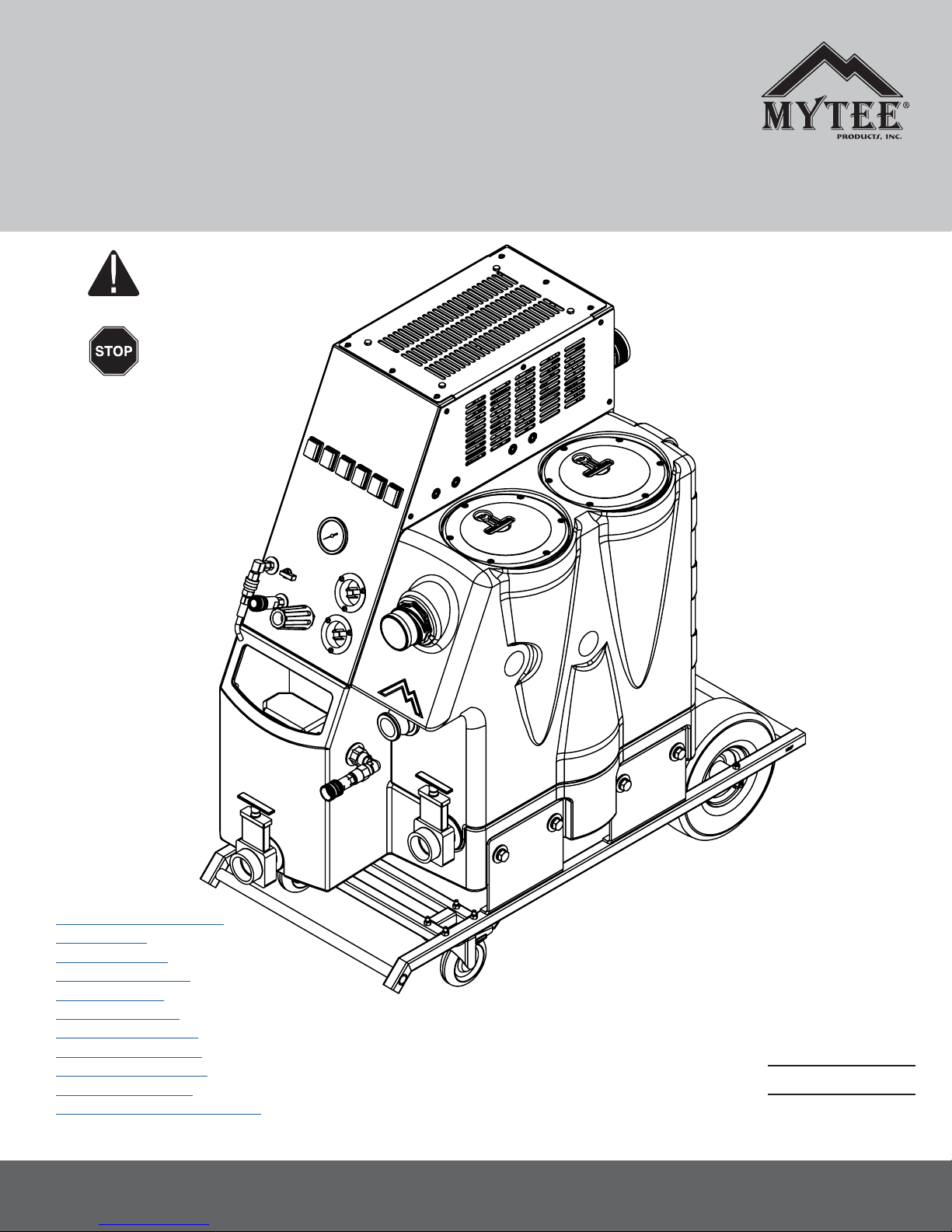
Instructions for
ESCAPE
Please read before use.
Register your product
at http://www.mytee.
com/support/register
™
ETM
General Information p. 2
Features p. 7
Switchplate p. 8
Power Options p. 9
Operation p. 10
Accessories p. 12
Parts & Pricing p. 14
Wiring Diagram p. 17
Vacuum System p. 19
Pump System p. 20
Auto Pump-Out System p. 21
Model #
Serial #
Form # ADP-ETM
9-17
13655 Stowe Dr., Poway, CA 92064
1
Page 2
GENERAL INFORMATION
Dear Customer:
Congratulations on the purchase of your new Escape™ ETM. As
technology continues to develop you can work condently knowing that
both Mytee Products Inc. and its employees are equally dedicated to
developing with the industry and its advances.
Like any other piece of machinery or technology, the ETM also requires
the proper maintenance and care to keep the product working over
extended use. Neglecting your machine, abusing it or not operating it
properly can void its warranty and prevent the machine from performing to
the quality and standard you’d expect out of the Mytee Products Inc. line.
If you have any warranty concerns or questions, please review this manual
thoroughly or do not hesitate to contact your distributor. If there are questions regarding maintenance, replacement or ordering parts please contact
an authorized Mytee Products Inc. Service Center. To see an updated list
please visit our website at http://www.mytee.com/support/service-centers/
Before using your Mytee Product, please read this manually thoroughly.
Sincerely,
Mytee Customer Care Dept.
Grounding Instructions
This machine must be grounded. If it should malfunction or breakdown,
grounding provides a path of least resistance for electrical shock. This machine is equipped with a cord having an equipment-grounding conductor
and grounding plug. The plug must be plugged into an appropriate outlet
that is properly installed in accordance with all local code and ordinances.
Do not remove ground pin; if missing, replace plug before use.
Improper installation of the equipment-grounding conductor can result
in a risk of electric shock. Be sure to check with a qualied electrician
or service person if you are in doubt as to whether the outlet is properly
grounded. If the plug will not t in the outlet do not modify either the plug
nor the machine’s cord, instead have a proper outlet installed by a qualied technician.
This machine is for use on a nominal 120-volt circuit and with a grounding
plug similar to the one in Figure 1 below. If a proper outlet is not available,
follow the illustrations of Figure 2 & 3 to install a temporary-grounding
plug. This temporary work-around should be used only until a proper outlet
(Figure 1) can be installed by a qualied electrician. When and if this type
of adapter is employed, screw the adapter’s extended tab into place with
a metal screw. However, grounding adapters are not approved for use in
Canada.
Again, be sure to check the grounding pin for damages and replace if
necessary.
The Green, or Green-Yellow, wire in the cord is the grounding wire. When
replacing a plug, this wire must be attached to only the grounding pin.
DO NOT use extension cords.
Please Note for America use only
Grounding Pin
Figure 1
Grounded Outlet
Metal
Screw
Grounded Outlet Box
Figure 2 Figure 3
Adapter
Tab for Grounding
Screw
Parts and Service
Please contact a Mytee service personnel or Mytee authorized Service
Center using Mytee original replacement parts and accessories for repairs
are needing to be performed. When and if calling Mytee for support,
please have your Model and Serial Number available for faster assistance.
Name Plate
The Model and Serial Number are located on the lower half of the back
of the machine near the power plugs and will be required for ordering
replacement parts. You can use the space provided on the front of this
manual to note down both for future referencing.
Unpacking the Machine
When your new machine is delivered, please carefully inspect both the
shipping carton and the machine for damages. If damage is evident, save
both the shipping carton and machine so that the delivering carrier can
inspect it. Contact the carrier immediately to le a freight claim if there has
been any damage.
Caution and Warnings
Symbols
Mytee uses the symbols below to signal potentially dangerous conditions.
Always read this information carefully and take the necessary steps to
protect personnel and property.
Is used to warn of immediate hazards that will cause severe personal
injury or death.
Is used to call attention to a situation that could cause severe personal
injury.
Is used to call attention to a situation that could cause minor personal
injury or damage to the machine or other property. When using an electrical appliance, basic precautions should always be followed, including the
following: Read all instructions before using this machine. This product is
intended for commercial use only.
To reduce the risk of re, electrical shock, or injury:
1. Read all instructions before using equipment.
2. Use only as described in this manual. Use only manufacturer’s recommended attachments.
3. Always unplug power cord from electrical outlet before attempting any
adjustments or repairs.
4. Do not unplug by pulling on cord. To unplug, grasp the plug, not the
cord.
5. Do not pull or carry by cord. Do not close a door on cord or pull cord
around sharp edges or corners.
6. Do not run appliance over cord. Keep cord away from heated surfaces.
7. Do not use with damaged cord or plug. If cord is damaged, repair
immediately.
8. Do not use outdoors or on wet surfaces and or standing water.
9. Always unplug or disconnect the appliance from power supply when
not in use.
10. Do not allow to be used as a toy. Close attention is necessary when
used by or near children.
11. Do not use in areas where ammable or combustible material may
be present.
12. Do not leave the unit exposed to harsh weather elements. Temperatures below freezing may damage components and void warranty.
13. Use only the appropriate handles to move and lift unit. Do not use any
other parts of this machine for this purpose.
14. Keep hair, loose clothing, ngers, and all parts of the body away from
2
Page 3

GENERAL INFORMATION
all openings and moving parts.
15. Use extra care when using on stairs.
16. To reduce the risk of re or electric shock, do not use this machine with
a solid-state speed control device.
17. The voltage and frequency indicated on the name plate must correspond to the wall receptacle supply voltage.
18. When cleaning and servicing the machine, local or national regulations
may apply to the safe disposal of liquids which may contain: chemicals,
grease, oil, acid, alkalines, or other dangerous liquids.
19. Do not leave operating unattended.
Escape Electronic Truckmount
Unpacking the Machine
When your new machine is delivered, please carefully inspect both the
shipping carton and the machine for damages. If damage is evident, save
both the shipping carton and machine so that the delivering carrier can
inspect it. Contact the carrier immediately to le a freight claim if there has
been any damage.
Installation:
Due to the variety of mounting conditions, Mytee Products Inc. does not
supply the necessary hardware to mount the ETM to the operating vehicle.
1. Do no attempt to move the ETM neither to nor from a vehicle with the
tanks full.
2. Please refer to a qualied technician for safe and proper installation into
your operating vehicle
Grounding Instructions
This machine MUST be grounded. If the machine should malfunction or
break down, grounding provides a path of least resistance for the electrical
current to safely dissipate. This machine is also manufactured with an
equipment-grounding conductor and grounding-plug. The plug must be
used on an appropriate outlet that is properly installed in accordance with
all local code and ordinances. Do not remove the ground pin. If it is missing, replace the plug prior to use. Improper installation of the equipmentgrounding conductor can result in a risk of electric shock. Be sure to check
with a qualied electrician or service person if you are in doubt as to
whether the outlet is properly grounded. If the plug will not t in the outlet
do not modify either the plug or the machine’s cord, instead have a proper
outlet installed by a qualied technician. This machine is for use on a
nominal 120-volt circuit and with a grounding plug. If a proper outlet is not
available, install a temporary-grounding plug. This temporary workaround
should be used only until a qualied electrician can install a proper outlet.
When and if this type of adapter is employed, screw the adapter’s ex-
tended tab into placewith a metal screw. However, grounding adapters are
not approved for use in Canada. Again, be sure to check the grounding pin
for damages and replace if necessary. The Green, or Green-Yellow, wire in
the cord is the grounding wire. When replacing a plug, this wire must be
attached to only the grounding pin. DO NOT use extension cords other
than provided.
Machine Specications
Solution Tank 12 gallons
Recovery Tank 12 gallons
Vacuum Quad 3-stage
CFM 325
Water Lift 230” or 16.5” Hg
Pump PSI 1,2 00
Pump GPM 2.4
Pump- Out GPM 35
Power
Consumption
Machine Weight 200 lbs.
Machine
Dimensions
Power Cord Dual twist-lock 50’ 12/3
Cord one: 20 amps @ 230V 60Hz/50Hz
Cord two: 10 amps @ 230V 60Hz /50Hz
Without cart: 32 ” x 21.25” x 36”
With cart: 43” x 21.25” x 44.25”
Operating Instructions:
POWER CORDS
There are four basic ways to power your ETM:
1. Plug converter box into 3 prong dryer outlet (230V), then plug both
power leads from the machine into the converter box.
2. Plug converter box into 4 prong dryer/range outlet (230V), then plug
both power leads from the machine into the converter box.
3. Plug one of the ETM cords into the 115V hunter box (sold separately),
which then plugs into two 115V outlets. This will allow you to use your
pump and two of your vacuums for cleaning.
4. Locate 4 115V outlets, and plug in both hunter boxes (sold separately).
This will allow you to run the entire unit. See the back of the converter
boxes for more details.
TO OPERATE
1. Attach the end of a garden hose to the auto-ll male QD and other end
to a water faucet.
2. Turn on the water until the automatic Shut-Off disengages water ow.
3. Using the hose attached to the primer, rest it inside the 2 ½” Vacuum
Port and turn both vacuums on.
4. Locate the Pump Prime and run valve and set to the prime position and
turn pump on.
5. Once water ows through prime hose switch the Prime Valve to run.
6. Regulate the PSI at ≤ 1000.
7. Attach the vacuum hose to the 2 ½” Cuff-Lynx hose port.
8. Connect a wand or other device to the front panel QD.
9. You may now begin cleaning.
10. When the vacuum shuts off you may need to drain the Recovery Tank
using one of the three methods:
a. Release the drain valve.
b. Activate the 35 GPM pump out.
11. When nished, be sure to drain any remaining uids from the hoses
and wands.
12. Shut off all the switches.
After Use
1. Before storing the machine, drain, rinse and dry both the tanks and
vacuum hoses of any residual water or solution.
2. Store standing upright in a dry, enclosed location.
3. Leave the recovery tank lid open for better air circulation.
If storing in freezing temperatures, take extra precautions to make sure the
machine and solution systems are completely drained and dry.
Filter Maintenance
All ETM models have three lters that need to be checked and cleaned
after each week of use. Regular cleaning and changing of lters is a
simple way to extend the life of your machines.
Vacuum Stack Filters
Located inside of the black vacuum tank are two pvc vacuum stacks.
Each stack has one foam lter to help prevent waste material from getting
into the vacuums and causing damage. To maintain these lters:
1. Remove 7” clear vacuum tank.
2. Reach in and pull out the two black lters located in the top ports of the
vacuum stacks.
3. Clean lters of any debris and check for damage. If lters are not
damaged, place them back into the stacks. If lters are damaged and
falling apart, replace them.
Pump Filter
The pump lter is a half-circle shaped screed located on the inside bottom
of the blue solution tank. To maintain lter:
1. Open black solution tank lid.
2. Reach into solution tank and rotate the dome shaped lter from its brass
nipple by rotating it counter clockwise.
3. Check lter for any debris or damage to screen. Rinse lter of any
debris or replace if damaged.
4. Place new or cleaned lter back onto brass nipple by rotating it
clockwise.
3
Page 4

GENERAL INFORMATION
ETM Float Switch Maintenance
Each ETM machine contains three water level oat switches. These oat
switches control certain functions of the machine. The rst oat switch will
control the auto-ll feature. The second oat switch controls power to the
vacuums. The third oat switch controls when the large sump pump
comes on and helps to prevent cavitation in the pump. Having these
prevents water from getting into the vacuum stacks and from spilling out
of the solution tank.
Vacuum Float Switch Maintenance and Replacement
Cleaning and maintaining oat switches will help to extend the life your
machine. Regular cleaning is required for proper functionality. To clean the
vacuum level switch:
1. Remove 7” clear vacuum tank lid located on top of the vacuum tank.
2. Use a ashlight to locate the position of the oat switch. The vacuum
tank oat switch will be located on the inside wall of the tank just below the
vacuum ports.
3. Once located, reach in and hold the oat switch nger all the way to one
side by pushing on the opposite side.
4. Using your other hand, or nger, roll the clip off of its tabs by pulling on
the bottom of the opposite tab from which you are pushing. It should not
take a lot of pressure to remove the switch, so be careful not to break it.
5. Check oat nger and where it attaches for debris or any other damage.
If dirty, clean. If damaged, or one of the male tabs where the oat hooks is
damaged, refer to the oat switch replacement section.
6. Once cleaned, replace oat nger, at side down, onto the male position
tabs located on the oat switch body in the vacuum tank. First, hook one
side of the nger to one tab. Then roll and pull the tab with index nger
until other clip snaps into place.
7. Check to insure oat still works by turning on both vacuums with the
vacuum tank lid off. Reach inside and lift the oat nger. If vacuums turn
off, the oat works. If the vacuums stay on, oat body may need replacement, or oat nger is installed upside down.
Vacuum Float Switch Replacement
Required:
-Colored tape
-New oat switch, rubber washer, and plastic nut
-Silicone
-Medium/deep depth 13/16” socket and ratchet
-Medium crescent wrench
-Philips screwdriver or drill
1. Using Philips head screw driver, remove ETM side panel by taking out
the ten Philips head screws holding panel onto machine.
2. Locate vacuum oat switch wires coming out of the black vacuum tank
directly under the vacuums. Disconnect the two oat switch wires that are
plugged into the system.
3. At this point, use the colored tape to mark the wires that the oat switch
was unplugged from. The back end of the vacuum oat switch should be
visible. Remove the 7” clear vacuum tank lid located on top of the vacuum
tank.
4. Use a ashlight to locate the position of the oat switch inside of the
tank. The vacuum oat switch will be located on the inside wall of the tank
below the vacuums.
5. Once located, reach in and hold the oat switch nger all the way to one
side by pushing on the opposite side.
1. Using your other hand, or nger, roll the clip off of its tabs by pulling on
the bottom of the opposite tab from which you are pushing. It should not
take a lot of pressure to remove the switch, so be careful not to break it.
2. Place the medium crescent wrench on the back nut of the oat switch
and the 13/16” socket on the inside nut of the oat switch. Loosen the oat
by rotating the ratchet counter clockwise until completely loose.
Make sure not to lose any nuts or rubber washers in case they are needed
in the future.
3. On the new oat switch, hold the oat switch nger all the way to one
side by pushing on the opposite side.
4. Using your other hand, or nger, roll the clip off of its tabs by pulling on
the bottom of the opposite tab from which you are pushing. It should not
take a lot of pressure to remove the switch, so be careful not to break it
5. Place the rubber washer over the threads of the new switch and all the
way down to the 13/16” nut side.
6. Place a thin layer of silicone on the rubber washer.
7. Thread oat switch (with actuating nger off) wires back through
vacuum tank hole and thread in using the 13/16” socket.
8. Using your hand, thread the plastic nut onto the back side of the oat
switch. Place medium crescent wrench on the nut to hold in place
9. Tighten the 13/16” oat until snug. Make sure at side of oat body is
facing towards the top of the vacuum tank.
10. Replace oat nger, at side down, onto the male position tabs located
on the oat switch body in the vacuum tank. First, hook one side of the
nger to one tab. Then roll and pull the tab with index nger until other clip
snaps into place.
11. Check to insure new oat switch works by turning on both vacuums
with the vacuum tank lid off. Reach inside and lift the oat nger. If vacuums turn off, the oat works. If the vacuums stay on or will not turn on,
the oat nger may be installed upside down or wires were not connected
completely.
Auto-ll Float Switch Maintenance and Replacement
Cleaning and maintaining oat switches will help
to extend the life your machine. Regular cleaning is
required for proper functionality. To clean the auto-ll
level switch:
1. Remove silver cover on the front of the blue solution tank by removing
the four Philips head screws.
2. Use a ashlight to locate the position of the oat switch. The auto-ll
oat switch will be located on the inside wall of the tank just below the
water inlet.
3. Once located, reach in and hold the oat switch nger all the way to one
side by pushing on the opposite side.
4. Using your other hand, or nger, roll the clip off of its tabs by pulling on
the bottom of the opposite tab from which you are pushing. It should not
take a lot of pressure to remove the switch, so be careful not to break it.
5. Check oat nger and where it attaches for debris or any other damage.
If dirty, clean. If damaged, or one of the male tabs where the oat hooks is
damaged, refer to the oat switch replacement section.
6. Once cleaned, replace oat nger, at side down, onto the male position
tabs located on the oat switch body in the vacuum tank. First, hook one
side of the nger to one tab. Then roll and pull the tab with index nger
until other clip snaps into place.
7. Check to insure oat still works by turning on both vacuums with the
vacuum tank lid off. Reach inside and lift the oat nger. If vacuums turn
off, the oat works. If the vacuums stay on, oat body may need replacement, or oat nger is installed upside down.
Auto-ll Float Switch Replacement
Required:
-Colored tape
-New oat switch, rubber washer, and plastic nut
-Silicone
-Medium/deep depth 13/16” socket and ratchet
-Medium crescent wrench
-Philips screwdriver or drill
1. Using Philips head screw driver, remove ETM side panel by taking out
the ten Philips head screws holding panel onto machine.
2. Locate vacuum oat switch wires coming out of the
blue solution tank directly behind the main pump. Disconnect the two oat
switch wires that are plugged into the system. At this point, use the
colored tape to mark the wires that the oat switch was unplugged from.
3. The back end of the vacuum oat switch should be visible.
4. Use a ashlight to locate the position of the oat switch inside of the
tank. The vacuum oat switch will be located on the inside wall of the tank
below the vacuums.
5. Once located, reach in and hold the oat switch nger all the way to one
side by pushing on the opposite side.
6. Using your other hand, or nger, roll the clip off of its tabs by pulling on
the bottom of the opposite tab from which you are pushing. It should not
take a lot of pressure to remove the switch, so be careful not to break it.
7. Place the medium crescent wrench on the back nut of the oat switch
4
Page 5

GENERAL INFORMATION
and the 13/16” socket on the inside nut of the oat switch. Loosen the oat
by rotating the ratchet counter clockwise until completely loose. Make sure
not to lose any nuts or rubber washers in case they are needed in the
future.
8. On the new oat switch, hold the oat switch nger all the way to one
side by pushing on the opposite side.
9. Using your other hand, or nger, roll the clip off of its tabs by pulling on
the bottom of the opposite tab from which you are pushing. It should not
take a lot of pressure to remove the switch, so be careful not to break it
10. Place the rubber washer over the threads of the new switch and all the
way down to the 13/16” nut side.
11. Place a thin layer of silicone on the rubber washer.
12. Thread oat switch (with actuating nger off) wires back through
vacuum tank hole and thread in using the 13/16” socket.
13. Using your hand, thread the plastic nut onto the back side of the oat
switch. Place medium crescent wrench on the nut to hold in place
14. Tighten the 13/16” oat until snug. Make sure at side of oat body is
facing towards the top of the vacuum tank.
15. Replace oat nger, at side down, onto the male position tabs located
on the oat switch body in the vacuum tank. First, hook one side of the
nger to one tab. Then roll and pull the tab with index nger until other clip
snaps into place.
16. Check to insure new oat switch works by turning on water for auto-ll
with the solution tank lid off. Reach inside and lift the oat nger. If water
stops, the oat works. If the water keeps running, the oat nger may be
installed upside down or wires were not connected completely.
Sump Pump Switch Maintenance and Replacement
Cleaning and maintaining oat switches will help to
extend the life your machine. Regular cleaning is
required for proper functionality. To clean the sump
level switch:
1. Remove 7” clear vacuum tank lid located on top of the vacuum tank.
2. Use a ashlight to locate the position of the oat switch. The sump
pump oat switch will be located on the inside wall of the tank almost at
the bottom.
3. Once located, reach in and hold the oat switch nger all the way to one
side by pushing on the opposite side.
4. Using your other hand, or nger, roll the clip off of its tabs by pulling on
the bottom of the opposite tab from which you are pushing. It should not
take a lot of pressure to remove the switch, so be careful not to break it.
5. Check oat nger and where it attaches for debris or any other damage.
If dirty, clean. If damaged, or one of the male tabs where the oat hooks is
damaged, refer to the oat switch replacement section.
6. Once cleaned, replace oat nger, at side up, onto the male position
tabs located on the oat switch body in the vacuum tank. First, hook one
side of the nger to one tab. Then roll and pull the tab with index nger
until other clip snaps into place.
7. Check to insure oat still works by turning on both vacuums with the
vacuum tank lid off. Reach inside and lift the oat nger. If vacuums turn
off, the oat works. If the vacuums stay on, oat body may need replacement, or oat nger is installed upside down.
Sump Pump Switch Replacement
Required:
-Colored tape
-New oat switch, rubber washer, and plastic nut
-Silicone
-Medium/deep depth 13/16” socket and ratchet
-Medium crescent wrench
-Philips screwdriver or drill
1. Using Philips head screw driver, remove ETM side panel by taking out
the ten Philips head screws holding panel onto machine.
2. Locate sump pump oat switch wires coming out of the black vacuum
tank directly under the behind the main pump. Disconnect the two oat
switch wires that are plugged into the system. At this point, use the colored
tape to mark the wires that the oat switch was unplugged from.
3. The back end of the vacuum oat switch should be visible. Remove the
7” clear vacuum tank lid located on top of the vacuum tank.
4. Use a ashlight to locate the position of the oat switch inside of the
tank. The sump pump switch will be located on the inside wall of the tank
near the bottom front.
5. Once located, reach in and hold the oat switch nger all the way to one
side by pushing on the opposite side.
6. Using your other hand, or nger, roll the clip off of its tabs by pulling on
the bottom of the opposite tab from which you are pushing. It should not
take a lot of pressure to remove the switch, so be careful not to break it.
7. Place the medium crescent wrench on the back nut of the oat switch
and the 13/16” socket on the inside nut of the oat switch. Loosen the
oat by rotating the ratchet counter clockwise until completely loose. Make
sure not to lose any nuts or rubber washers in case they are needed in the
future.
8. On the new oat switch, hold the oat switch nger all the way to one
side by pushing on the opposite side.
9. Using your other hand, or nger, roll the clip off of its tabs by pulling on
the bottom of the opposite tab from which you are pushing. It should not
take a lot of pressure to remove the switch, so be careful not to break it
10. Place the rubber washer over the threads of the new switch and all the
way down to the 13/16” nut side.
11. Place a thin layer of silicone on the rubber washer.
12. Thread oat switch (with actuating nger off) wires back through
vacuum tank hole and thread in using the 13/16” socket.
13. Using your hand, thread the plastic nut onto the back side of the oat
switch. Place medium crescent wrench on the nut to hold in place
14. Tighten the 13/16” oat until snug. Make sure at side of oat body is
facing towards the BOTTOM of the vacuum tank. This is the ONLY switch
that will be positioned this way.
15. Replace oat nger, at side up, onto the male position tabs located
on the oat switch body in the vacuum tank. First, hook one side of the
nger to one tab. Then roll and pull the tab with index nger until other clip
snaps into place.
16. Check to insure new oat switch works by turning on the sump pump
on with the vac tank lid off. Reach inside and lift the oat nger. If sump
turns on. The oat works. If the sump will not turn on, or will not turn off,
the oat nger may be installed upside down or wires were not connected
completely.
Maintenance item Daily Once a week
Clean and inspect tanks.
Clean and inspect hoses.
Check and clean internal lters by twisting
off, rinsing with clean water and replacing.
Check power supply cable.
Clean machine with all-purpose cleaner
and cloth.
Check spray nozzles.
Flush solution system with Mytee® System
Maintainer.
Remove and oat shut-off screen from
tank and clean. Simply pull off.
Inspect vacuum hoses for holes and loose
cuffs.
Inspect spray pattern for clogging. If
clogged, remove spray tips and soak them
in a recommended liquid neutralizer for
up to six hours. To remove spray tip, twist
spray tip body counter-clockwise.
Lubricate wheels with water resistant oil.
Inspect machine for water leaks and loose
hardware.
x
x
x
x
x
x
x
x
x
x
x
x
Generators for use with Escape® Electric Truck Mount
Mytee Products recommends the use of a 10,000- ‐watt generator with
this unit. This will supply ample power for the ETM.
However, the Escape can be run on some 8,000- ‐watt generators, depending on the manufacturer. Generators are rated differently, so if
using 8,000- ‐watt generator the rating must represent continuous running
5
Page 6

GENERAL INFORMATION
watts, not peak watts.
In any case, check with the Generator manufacturer to ensure the unit
can provide 30 amps at 230 volts continuously.
6
Page 7
REVISIONS
REV.
DESCRIPTION
DATE
APPROVED
OD
ORIGINAL DRAFT
JFL
D
C
B
8
7
6
5
4
3
2
1
E
F
12/2013
UNLESS OTHERWISE SPECIFIED:
TITLE:
NAME
DATE
CHECKED
DRAWN
DIMENSIONS ARE IN INCHES
TOLERANCES:
ANGULAR: MACH
.5
858-679-1191
mytee
PRODUCTS, INC.
V. LaBarbera
ESCAPE™ ETM
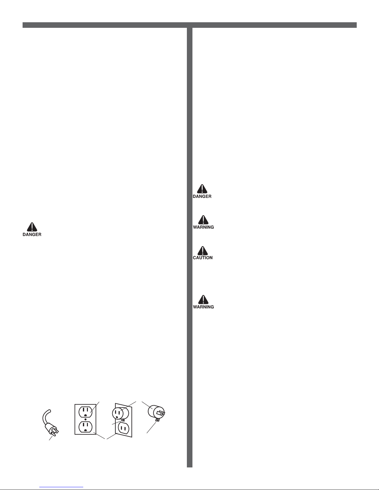
ESCAPE™ ETM BACKESCAPE™ ETM FRONT
12
1
2
3
4
5
6
7
1. Switch Plate
2. Prime Valve
3. Female Quick Disconnect
(QD)
4. Pressure Regulator
5. Electrical Power Ports
6. Solution Tank Drain Valve
7. Auto Fill
11
10
9
8
8. Recovery Tank Drain Valve
9. Pump-Out
10. 2” Male Cuff-Lynx™ Inlet
11. PSI Gauge
13
14
15
12. Recovery Lids
13. Recovery Tank
14. 4” Locking Casters
15. Cart
16. 10” foam lled wheels
17. Rear Cooling Fans
18. Top, Rear & Side Vents
19. Rear Vacuum Exhaust
19
18
17
16
ESCAPE™ ETM ACCESSORY ITEMS INCLUDED
H107 Cuff-Lynx™
2.5” x 2.5” Hose Adapter
5005
3-prong Electrical Converter
H106 Cuff-Lynx™
2.5” x 2” Hose Reducer
5006
4-prong Electrical Converter
7
Page 8

ESCAPE™ ETM
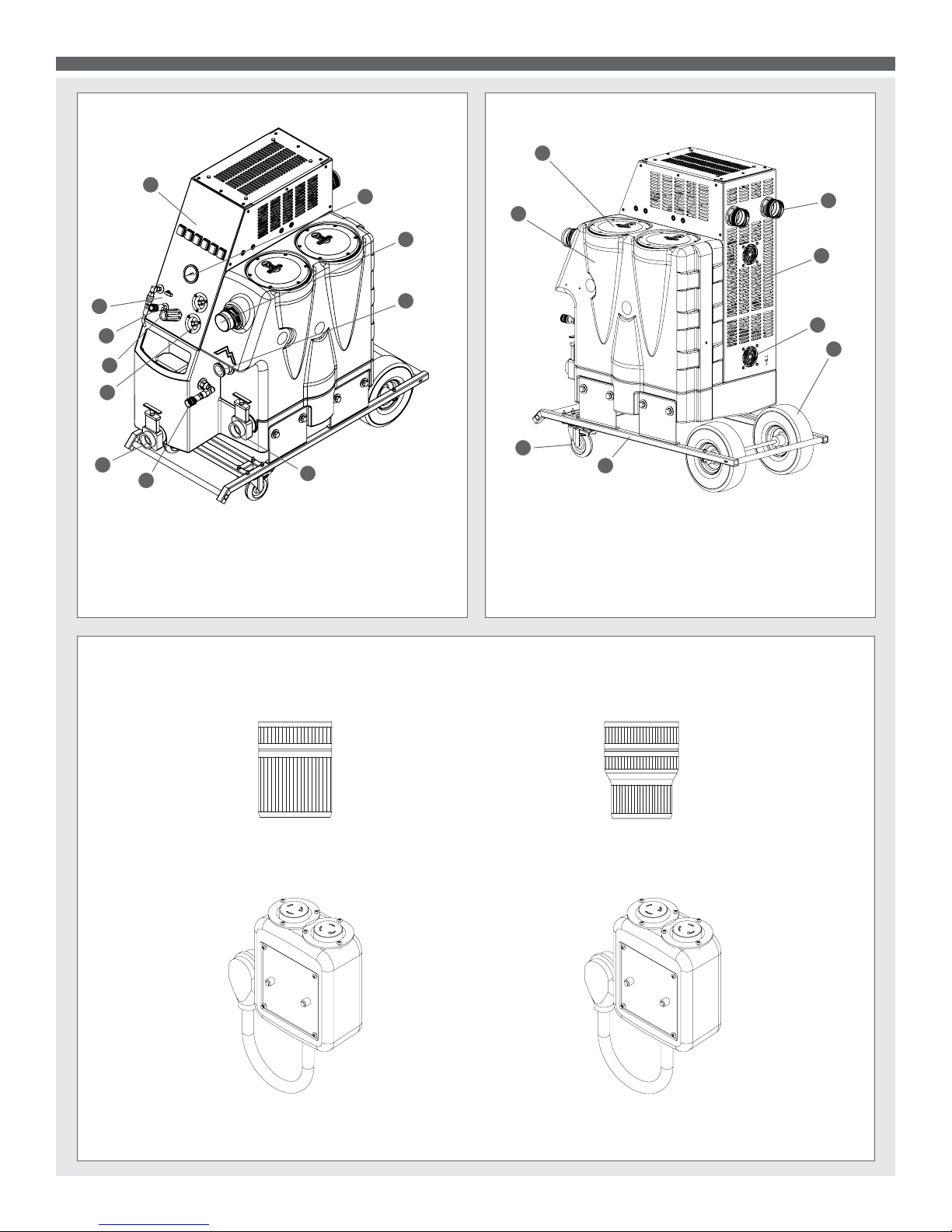
ESCAPE™ ETM SWITCH PLATE AND POWER SOCKETS
Top Socket: Powers Vac 1, Vac 2 Pump, & Pump-out.
Bottom Socket: Powers Vac 3 and Vac 4.
Top power socket
Bottom power socket
Plug in to top socket to use vacuum 1 or 2, pump or pump-out. To use vacuum 3 or 4 plug in bottom socket.
8
Page 9

*sold separately
ESCAPE™ ETM
ESCAPE™ ETM POWER OPTIONS 1 & 2
Plug each 50’ power cord into the 3 or 4 prong electrical adaptor. Once connected, plug electrical adaptor into dryer outlet.
ESCAPE™ ETM POWER OPTION 3 USING HUNTER BOXES (SOLD SEPARATELY)
*
*
Plug each 50’ power cord in the hunter boxes (sold separately - part # 5007). Once connected to the hunter boxes, plug each cord in to four
separate 115 volt electrical legs.
9
Page 10

ESCAPE™ ETM
ESCAPE™ ETM PSI GAUGE & REGULATOR
The gauge allows you to monitor PSI levels. Turning the Pressure
Regulator to its left will decrease water pressure and turning to the
right will increase water pressure. *Please refer to the Pressure
Gauge to monitor your water pressure.
ESCAPE™ ETM PUMP PRIME / WASH OUT HOSE
The wash out hose is available for rinsing out recovery tank.
ESCAPE™ ETM SOLUTION HOSE AND VACUUM HOOK UP
Attach female end of a solution hose to a wand or tool then attach male end of QD to ETM. Attach hose along with a 2.5” Cuff-Lynx™ hose
adapter to the ETM’s hose port. Then connect a vacuum hose or tool to other end of hose.
10
Page 11

ESCAPE™ ETM
ESCAPE™ ETM AUTO FILL & SOLUTION TANK DUMP VALVE
For a convienent way to ll up the ETM’s solution tank, connect a water hose to the auto-ll. This will help speed up the work ow. Once the
water level reaches a certain point the water stops, then rells again. Empty the solution tank by pulling the solution tank dump valve.
ESCAPE™ ETM PUMP OUT HOOK UP &
ESCAPE™ ETM CLEAR T - LIDS
RECOVERY TANK DUMP VALVE
Attach hose bearing cam lock to the Pump-out tting. Secure the
hose to the tting using the cam lock. Push the hose cuff onto
the tting, making sure the silver ears and rings are extended
forward. Pull the ears down using the rings until connection is
tight. Place the end of the hose in a location where dirty water
can drain. Using the recovery tank drain valve is also available.
Recovery tank lids for easy entry.
11
Page 12

ESCAPE™ ETM ACCESSORIES
D
C
B
2
1
E
F
D
C
B
2
1
E
F
T-80R - Recovery Tank T-80S - Solution Tank
A500 - Stackable Van
T-REX™ - Total
Rotary Extraction
Shelving System Set
T-REX™ Jr. - Total
Rotary Extraction
12
Page 13

ESCAPE™ ETM ACCESSORIES
REVISIONS
REV.
DESCRIPTION
DATE
APPROVED
OD
ORIGINAL DRAFT
JFL
D
C
B
6
5
4
3
2
1
E
F
2/5/10
UNLESS OTHERWISE SPECIFIED:
TITLE:
NAME
DATE
COMMENTS:
CHECKED
DRAWN
DIMENSIONS ARE IN INCHES
TOLERANCES:
ANGULAR: MACH
.5
ONE PLACE DECIMAL
.03
A
858-679-1191
mytee
PRODUCTS, INC.
V. LaBarbera
8901 - Wand Style
2” Spinner®
8902 - “T” Style
2” Spinner®
8908 - Counter Spinner®
13
Page 14

ESCAPE™ ETM PARTS & PRICING
ITEMS NOT SHOWN
ITEM
NO.
PART NO.
DESCRIPTION
QTY.
MSRP
1
P505
ETM Sol Tank / Chassis
1
$224.99 ea
2
H541A
valve, float, autofill
1
$108.99 ea
3
H097
washer, 1"ID x 1.5"OD, flat, s/s
2
$0.99 ea
4
B182
adapter, 3/4" fgh x 1/2" fpt
1
$12.99 ea
5
B273
elbow, 90 deg street, 3/8"fpt x 1/2" mpt
1
$8.99 ea
6
H541C
chemical injector
1
$39.99 ea
7
B204
qd, 3/4" female x female garden hose
1
$9.99 ea
8
B205B
QD, 1/2" npt x 3/4" mgh, pump-out
1
$3.99 ea
9
B272
adapter, 1/2" fpt x 3/8 mpt
1
$16.99 ea
10
PH634-33 sol hose, 1/4", silicone braided, clear
1
$6.49 ft
11
B170
ferrule, 1/4" brass
6
$0.99 ea
12
B109
adapter, brass, 1/4" barb x 1/4" mpt
4
$1.99 ea
13
H484
plate, mounting, QD
1
$4.99 ea
14
B656B
valve, ball, 1/4" fpt x 1/4" fpt, s/s
2
$13.49 ea
15
B127
plug, brass, 1/4"mpt, hex
2
$0.99 ea
16
H230
screw, 10-32 x 1/2" phil pan head, s/s 38
$0.99 ea
17
H225
valve, drain, 1-1/2"
2
$20.99 ea
18
H203
bolt, 1/4-20 x 1-1/4" hex head, s/s
2
$0.99 ea
19
H213
washer, 1/4" lock, s/s
10
$0.99 ea
20
H210
washer, 1/4" flat, s/s
10
$0.99 ea
21
H196
support, pump, truckmount
1
$18.99 ea
22
H201
bolt, 1/4-20 x 1/2" hex head, zinc
2
$0.99 ea
23
PH615-35 sol hose, 1/2", silicone braided clear
1
$8.99 ft
24
B173
ferrule, 1/2", brass
3
$0.99 ea
25
B644
adapter, brass, 1/2" barb x 1/4" mpt
1
$2.49 ea
26
B119
filter, strainer, 1/4"
1
$3.99 ea
27
H012
instrument panel, truck mount
1
$185.99 ea
28
E628A
controller, water level, single, 230V
1
$114.99 ea
29
H273
nut, kep, #10-32 zinc
7
$0.99 ea
30
E360
flanged male inlet recaptacle, 230V, 20A
2
$28.99 ea
31
PH634-20 sol hose, 1/4", silicone braided, clear
1
$6.49 ft
32
H046
screw, 10-32 x 3/8", phil pan, zinc
2
$0.99 ea
33
H289
washer, 10 flat, s/s
2
$0.99 ea
34
AH184
hose, pulse, 3/8" x 14.5", 1/4 FSW x 1/4 FPT
2
$27.99 ea
35
PH634-24 sol hose, 1/4", silicone braided, clear
1
$6.49 ft
36
B652
elbow, brass, 90 deg, 3/8"mpt x 1/4"mpt
2
$8.49 ea
37
H306C
unloader, 1200 psi
1
$125.99 ea
38
B103
elbow, brass, 90 deg, 1/4"mpt x 1/4" fpt
8
$4.49 ea
39
H876
washer, 1/2" flat, s/s
5
$0.99 ea
40
B111
adapter, brass, extender, 1/4" mpt x 1/4" fpt, hex
2
$3.49 ea
41
B102
qd, brass, 1/4" f x 1/4" fpt
1
$17.99 ea
42
B142A
coupling, brass, 1/4" fpt x 1/4" fpt
4
$4.49 ea
43
B135
tee, brass, 1/4" mpt
1
$5.49 ea
44
PH634-36 sol hose, 1/4", silicone braided, clear
1
$6.49 ft
45
B110
adapter, brass, 1/4" sw barb x 1/4" fpt, w/gasket
1
$3.99 ea
46
B259
qd, brass, 1/4" fqd x mpt
1
$11.99 ea
47
B260
qd, brass, 1/4" mqd x fpt
1
$10.49 ea
48
B107
nipple, brass, 1/4"m, hex
4
$3.19 ea
49
B136
elbow, brass, 90 deg, 1/4" mpt x 1/4" mpt
3
$4.99 ea
50
H325
flow meter, electric truckmount
1
$189.99 ea
51
G069
gasket, flow meter
1
$0.99 ea
52
B129
nipple, hex, 1/8" mpt x 1/8" mpt
2
$1.99 ea
53
B131
fitting, 1/4" barb x 1/8" FPT
2
$2.99 ea
54
H308D
gauge, pressure, 2000psi
1
$38.99 ea
55
B130
45 deg, street elbow, brass, 1/4" male
1
$5.49 ea
56
E369
hour meter, panel mount, analog
1
$35.99 ea
57
E515
switch, rocker, 2 position
6
$13.99 ea
58
H009
side panel, truckmount
1
$189.99 ea
59
P535
bottle, 5 quart, w/ caps
1
$16.99 ea
60
G036
cap, 2.5" threaded, tethered
1
$3.49 ea
61
H547
hanger, wire for injection sprayer
1
$7.49 ea
62
H456B
cap (only) w/ hole
1
$3.99 ea
63
PH634-35 sol hose, 1/4", silicone braided, clear
1
$6.49 ft
64
B117
strainer, with check, chemical injector
1
$18.99 ea
65
C332
pump head, general, 2.1 GPM
1
$569.99 ea
66
B186
elbow, brass, 90 deg, 3/8"mpt x 3/8" fmpt
1
$8.99 ea
67
B172
elbow, brass, 90 deg, 1/2" barb x 3/8"mpt
1
$9.49 ea
68
B105
bushing, brass, 3/8"mpt x 1/4"
1
$3.19 ea
PART NO.
DESCRIPTION
QTY.
MSRP
A959
harness, electrical
1
$74.99 ea
E351
power cord, ext, 50', 12/3, twist lock
2
$78.99 ea
H106
Cuff-Lynx, 2" hose x 2.5" female
1
$4.99 ea
H107
Cuff-Lynx 2.5" hose x 2.5" f swivel
1
$4.99 ea
H294
vac hose, 1-1/2" x 25' SW 1
$74.99 ea
H205
cam & groove fitting 1-1/2", female w/ lock
1
$32.99 ea
5005
electrical adaptor ETM - 3 prong
1
$169.99 ea
5006
electrical adaptor ETM - 4 prong
1
$159.99 ea
ADM-ETM
ETM manual
1
ITEM
NO.
PART NO.
DESCRIPTION
QTY.
MSRP
69
C329
motor, for pump, 1 HP, 1725 RPM
1
$359.99 ea
70
AH203
hose, pulse, 3/8" x 34", (OAL)
2
$47.99 ea
71
B113
tee, brass, 1/4" fpt
1
$6.99 ea
72
B643 adapter, brass, 3/8" fnpt x 1/4" mnpt
2
$4.99 ea
73
C304
motor, 3-stage, 115 cfm,14.5 amps
4
$199.99 ea
74
H217
clamp, hose, 2-1/4 dia
9
$1.49 ea
75
PH628-16
vac hose, 2", black, wire reinforced
2
$8.99 ft
76
H768
bolt, 1/4-20 x 3/4" serrated hex flange, zinc
6
$0.99 ea
77
H501
vac support, 3 stage, 4-1/16"
6
$4.99 ea
78
G004
gasket, vacuum motor
4
$8.99 ea
79
P735
manifold, single vac, no gasket
2
$14.99 ea
80
PH628-2.5
vac hose, 2", black, wire reinforced
1
$8.99 ft
81
PH628-17
vac hose, 2", black, wire reinforced
1
$8.99 ft
82
E370A
controller, 230v, water level switch, dual vac
2
$133.99 ea
83
H343
screw, 10 x 5/8" hex head, zinc
4
$0.99 ea
84
C318
fan, cooling, 230V
1
$21.49 ea
85
H001
side panel, small, truckmount
1
$99.99 ea
86
H011
back panel, truckmount
1
$185.99 ea
87
H124
Cuff-Lynx, 2" mpt x 2" female cuff
2
$3.99 ea
88
H304
screw, #8 x 5/8 phil oval, s/s
15
$0.99 ea
89
G090 lid, vac tank, clear, 7"
2
$36.99 ea
90
G091
gasket, 7", vac lid
2
$11.99 ea
91
P508
deflector, LX \ ETM
1
$21.99 ea
92
G022
filter, foam, 2-3/8" x 1"
2
$2.99 ea
93
H045
screen, 4" diameter, 1/4" mesh
2
$6.99 ea
94
G004-A gasket, vacuum motor
2
$6.99 ea
95
H096
bolt, hex, 1/4-20 x 4", zinc Finish
6
$0.99 ea
96
H064-A U, ETM vac
2
$9.99 ea
97
H503
vac support, 3 stage, 3.25", no thrds
6
$3.99 ea
98
H073
coupler, 2.5" dia x 9.5", ss
1
$23.99 ea
99
E373
level switch, vacuum shut-off, rear threads
3
$13.99 ea
100
H132
Cuff-Lynx, 2.5" m cuff x 2.5" mpt
1
$4.99 ea
101
H207
cam & grovve fitting 1-1/2", male
1
$21.99 ea
102
P506
ETM Vac Tank
1
$219.99 ea
103
C384A
pump out, 35 gpm, 230v, stainless
1
$598 .99 ea
104
H396
barb, 1-1/2" x 1-1/2" fpt, pump out 1
$19.99 ea
105
H300
cuff, hose, 1-1/2 x 1-1/2, wire
1
$5.99 ea
106
PH627-20
vac hose, 1-1/2", black, wire reinforced
1
$6.99 ft
107
P686 swing check valve, pump out
1
$24.49 ea
108
H185
screw, 10-32 x 1 1/4", phil flat full thread
1
$0.99 ea
109
H059
bracket, ETM, pump-out
1
$9.99 ea
110
H010
top panel, truckmount
1
$99.99 ea
111
H062
vac mounting plate, ETM
1
$39.99 ea
112
H202
bolt, 1/4-20 x 3/4" hex head, s/s
10
$0.99 ea
113
H216
nut, lock, 1/4-20, nylon insert, s/s
14
$0.99 ea
114
H174
bolt, 1/2-13 x 3/4, c/s, hex head
8
$0.99 ea
115
H173
washer, lock, 1/2 med split, steel zinc
8
$0.99 ea
116
H254
washer, axle, cut 1/2" id
8
$0.99 ea
117
H057
cart, ETM
1
$399.99 ea
118
H668
caster, 4", black hub & gray tread
2
$19.49 ea
119
H204
bolt, 1/4-20 x 1-3/4" hex head, s/s
10
$0.99 ea
120
H109
wheel, 10", foam filled
2
$79.99 ea
121
H058
axle, ETM cart
1
$18.99 ea
D
C
B
A
B
C
D
1
2
3
4
5
6
7
8
8
7
6
5
4
3
2
1
E
F
E
F
ETM_230v
SHEET 1 OF 5
ETM
12/2013
E
SCALE: 1:8
REV
DWG. NO.
C
SIZE
TITLE:
NAME
DATE
COMMENTS:
CHECKED
DRAWN
PROPRIETARY AND CONFIDENTIAL
THE INFORMATION CONTAINED IN THIS
DRAWING IS THE SOLE PROPERTY OF
MYTEE PRODUCTS, INC. ANY
REPRODUCTION IN PART OR AS A WHOLE
WITHOUT THE WRITTEN PERMISSION OF
MYTEE PRODUCTS, INC. IS
PROHIBITED.
A
DO NOT
SCALE DRAWING
858-679-1191
mytee
PRODUCTS, INC.
M.LaBarbera
14
Part prices are subject to change.
Page 15

ESCAPE™ ETM PARTS & PRICING
59
60
62
63
61
16
58
16
21
22
31
25
26
38
41
52
100
89
103
107
106
85
16
73
79
78
77
76
75
74
17
105
104
101
49
14
1
116
115
114
10
12
13
16
14
15
17
2
4
16
86
88
16
72
38
71
49
66
67
23
69
65
53
72
81
80
87
70
18
19
20
28
29
30
16
27
57
56
55
54
51
50
32
33
37
36
90
91
73
78
93
92
97
19
20
95
5
6
9
8
7
19
20
68
12
38
39
48
40
38
47
46
45
44
35
15
12
39
40
43
42
64
96
99
38
42
48
39
109
102
24
88
3
3
29
108
82
16
to sol tank
to sol tank
to PH634-11
10
to pressure
gauge
thru B130
55
to unloader
thru B136
36
to flow meter
thru B131
53
to 7qt
bottle thru
PH634-32
63
24
11
11
98
35
11
38
34
94
D
C
B
A
B
C
D
1
2
3
4
5
6
7
8
8
7
6
5
4
3
2
1
E
F
E
F
ETM_230v
SHEET 2 OF 5
ETM
12/2013
E
SCALE: 1:8
REV
DWG. NO.
C
SIZE
TITLE:
NAME
DATE
COMMENTS:
CHECKED
DRAWN
PROPRIETARY AND CONFIDENTIAL
THE INFORMATION CONTAINED IN THIS
DRAWING IS THE SOLE PROPERTY OF
MYTEE PRODUCTS, INC. ANY
REPRODUCTION IN PART OR AS A WHOLE
WITHOUT THE WRITTEN PERMISSION OF
MYTEE PRODUCTS, INC. IS
PROHIBITED.
A
DO NOT
SCALE DRAWING
858-679-1191
mytee
PRODUCTS, INC.
M.LaBarbera
15
Page 16

ESCAPE™ ETM PARTS & PRICING
16
112
111
112
113
114
115
116
117
113
119
118
120
121
113
119
D
C
B
A
B
C
D
1
2
3
4
5
6
7
8
8
7
6
5
4
3
2
1
E
F
E
F
ETM_230v
SHEET 3 OF 5
ETM
12/2013
E
SCALE: 1:8
REV
DWG. NO.
C
SIZE
TITLE:
NAME
DATE
COMMENTS:
CHECKED
DRAWN
PROPRIETARY AND CONFIDENTIAL
THE INFORMATION CONTAINED IN THIS
DRAWING IS THE SOLE PROPERTY OF
MYTEE PRODUCTS, INC. ANY
REPRODUCTION IN PART OR AS A WHOLE
WITHOUT THE WRITTEN PERMISSION OF
MYTEE PRODUCTS, INC. IS
PROHIBITED.
A
DO NOT
SCALE DRAWING
858-679-1191
mytee
PRODUCTS, INC.
V. LaBarbera
16
Page 17

ESCAPE™ ETM LOWER WIRING DIAGRAM
Electric Truck Mount - 230 Volt
Hour Meter
VAC
1
VAC
2
Pump
VAC 1
L2L1
G
VAC 2
L2L1
G
Pump
L2L1
G
Pump
Out
Pump
Out
L2L1
G
230
Volts
G
X
Y
Cooling
Fan
N/O
Switch
Twist lock Flanged
Receptacle
C-304
C-304
C-384A
C-332
E-369
C-318
E-360
To Metal
Plate
To Metal
Plate
To Metal
Plate
To Metal
Plate
230V
Relays
Float
Switch
L1
Float
Switch
Relay
230V
L1
E-628
N/O
Switch
3/12/2013
E-370
Red wires are 12 gauge
17
Page 18

ESCAPE™ ETM UPPER WIRING DIAGRAM
VAC 3
L2L1
G
VAC 4
L2L1
G
VAC 4
Twist Lock Flanged
Receptacle
230
volts
Ground Wire
to metal
faceplate
C-304
C-304
E-360
N/O
E-373
L1
L2
G
Cooling
Fan
C-318
VAC 3
230V
Relays
Float
Switch
L1
Electric Truck Mount - 230 Volt
3/12/2013
E-370
Red wires are 12 gauge
18
Page 19

ESCAPE™ ETM VACUUM SYSTEM
Vacuum System
Cabinet
Tank
Vac 3Vac 4
Vac 2
Vac 1
Vac Motors
w/ gasket
Foam Filter-
clean regularly
for maximum CFM
Mesh Screen
Air Flow
Air Flow
Air Flow
Vac Control Boxes-
Each box controls 1
level switch. Boxes
should always be
set to 230V.
Vacs 3 & 4
Cord #2. Mounted
to cabinet top
Vacs 1 & 2
Cord #1. Mounted
to the tank wall.
2 vac shuto
switches in tank-
Each controls 1 set
of vacs (1&2 or 3&4).
Should be cleaned
regularly.
Cu Lynx
Miliamp Current
Miliamp Current
19
Page 20

ESCAPE™ ETM HIGH PRESSURE PUMP SYSTEM
High Pressure Pump System
Inlet Hose
Pressure
Gauge
Pressure
Regulator
Solution
Quick Disconnect
Filter
In Tank.
Clean Regularly.
Bypass Hose To Tank
= High Pressure
= Low Pressure
20
Page 21

ESCAPE™ ETM AUTO PUMP-OUT SYSTEM
Male Cam
Fitting
Auto Pump-Out Pump
Vacuum HoseCheck Valve-
keeps vacuum
from leaking
through pump
Auto Pump-Out System
Level Switch-
Controls pumps
On/O
. Clean
regularly.
21
Page 22

NOTES
Mytee Products Inc.
13655 Stowe Dr.
Poway, CA 92064
www.mytee.com
FX 858.679.7814
© 2017 Mytee Products Inc.
Printed in the U.S.A.
22
 Loading...