

Page 1

Instructions for
20-110 Deluxe Prep-Center
Please read before use.
™
General Information p. 2
Set Up p. 5
Parts & Pricing p. 9
Wiring Diagram p.11
Notes p.12
Model #
Serial #
Form # ADP-20-110
7-16
1
Page 2
GENERAL INFORMATION
Dear Customer:
Congratulations on the purchase of your new 20-110 Deluxe Prep- Center™. As you
are already aware, the scene of the equipment world is becoming more high tech,
and we at Mytee Products Inc. strive to keep you on the cutting edge with superior
quality and technology.
Keep in mind that 20-110 Deluxe Prep- Center™ is a machine, so neglect or abuse
will cause unnecessary damage and void the warranty. However with simple
maintenance the 20-110 will give quality performance for many years to come.
If warranty questions arise, please consult your user manual or get in touch with
your distributor. If you have questions about maintenance, replacing parts or
ordering parts, please call an authorized Mytee Products Inc. Service Center.
To see an updated list, visit our website at www.mytee.com
Before you begin cleaning, please read your manual thoroughly.
Sincerely,
Mytee Customer Care Dept.
Grounding Instructions
This machine must be grounded when being recharged. If it should malfunction or
breakdown, grounding provides a path of least resistance for electrical shock. This
machine is equipped with a cord having an equipment-grounding conductor and
grounding plug. The plug must be plugged into an appropriate outlet that is properly
installed in accordance with all local code and ordinances. Do not remove ground
pin; if missing, replace plug before use.
Improper connection of the equipment-grounding conductor can result in a risk of
electric shock. Check with a qualied electrician or service person if you are in doubt
as to whether the outlet is properly grounded. Do not modify the plug provided with
the machine. If it will not t the outlet, have a proper outlet installed by a qualied
electrician.
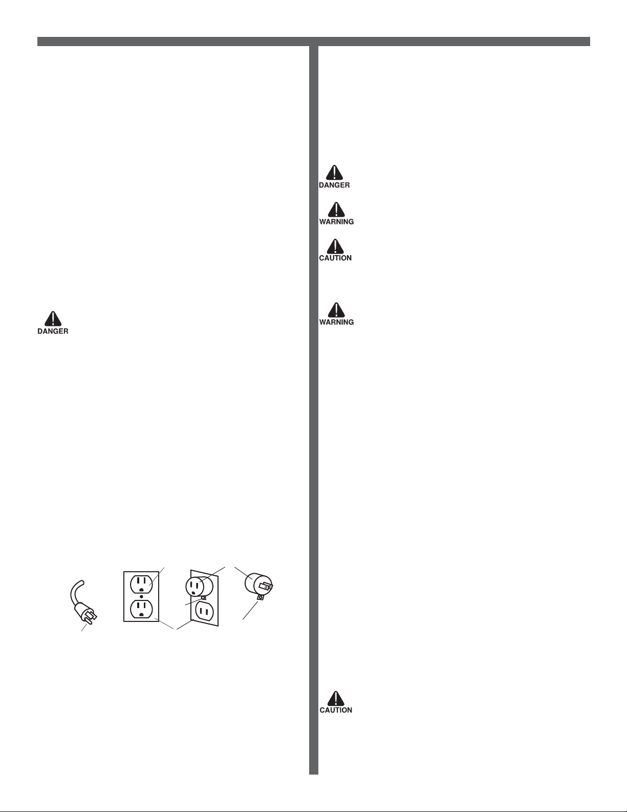
This appliance is for use on a nominal 120-volt circuit, and has a grounding plug
that looks like the plug illustrated in Figure 1 below. A temporary adapter illustrated
in Figures 2 and 3 may be used~to connect this plug to a 2-pole receptacle as
shown in Figure 2 if a properly grounded outlet is not available. The temporary
adapter should be used only until a properly grounded outlet (Figure 1) can be
installed by a qualied electrician. The green colored rigid ear, tab or the like
extending from the adapter must be connected to a permanent ground such as a
properly grounded outlet box cover. Whenever the adapter is used, it must be held
in place by a metal screw. Grounding adapters are not approved for use in Canada.
Replace the plug if the grounding pin is damaged or broken.
The Green (or GreenYellow) wire in the cord is the grounding wire. When replacing
a plug, this wire must be attached to the grounding pin only.
DO NOT use extension cords.
Please Note for America use only
Grounding Pin
Grounded Outlet
Metal
Screw
Grounded Outlet Box
Figure 1
Adapter
Tab for Grounding
Screw
Figure 2 Figure 3
Parts and Service
Repairs, when required, should be performed by Mytee service personnel or Mytee
authorized Service Center using Mytee original replacement parts and accessories.
Call Mytee for repair parts or service. Please specify the Model and Serial Number
when discussing your machine.
Unpacking the Machine
When the machine is delivered, carefully inspect the shipping carton and the
machine for damage. If damage is evident, save the shipping carton so that it can
be inspected by the carrier that delivered it. Contact the carrier immediately to le a
freight damage claim.
Caution and Warnings
Symbols
Mytee uses the symbols below to signal potentially dangerous conditions. Always
read this information carefully and take the necessary steps to protect personnel
and property.
Is used to warn of immediate hazards that will cause severe personal injury or death.
Is used to call attention to a situation that could cause severe personal injury.
Is used to call attention to a situation that could cause minor personal injury or
damage to the machine or other property. When using an electrical appliance, basic
precautions should always be followed, including the following: Read all instructions
before using this machine. This product is intended for commercial use only.
To reduce the risk of re, electrical shock, or injury:
1. Read all instructions before using equipment.
2. Use only as described in this manual. Use only manufacturer’s recommended
attachments.
3. Always unplug power cord from electrical outlet before attempting any adjustments
or repairs.
4. Do not unplug by pulling on cord. To unplug, grasp the plug, not the cord.
5. Do not pull or carry by cord. Do not close a door on cord or pull cord around sharp
edges or corners.
6. Do not run appliance over cord. Keep cord away from heated surfaces.
7. Do not use with damaged cord or plug. If cord is damaged, repair immediately.
8. Do not use outdoors or on wet surfaces and or standing water.
9. Always unplug or disconnect the appliance from power supply when not in use.
10. Do not allow to be used as a toy. Close attention is necessary when used by or
near children.
11. Do not use in areas where ammable or combustible material may be present.
12. Do not leave the unit exposed to harsh weather elements. Temperatures below
freezing may damage components and void warranty.
13. Use only the appropriate handles to move and lift unit. Do not use any other parts
of this machine for this purpose.
14. Keep hair, loose clothing, ngers, and all parts of the body away from all
openings and moving parts.
15. Use extra care when cleaning on stairs.
16. To reduce the risk of re or electric shock, do not use this machine with a solid-
state speed control device.
17. The voltage and frequency indicated on the name plate must correspond to the
wall receptacle supply voltage.
18. When cleaning and servicing the machine, local or national regulations may apply
to the safe disposal of liquids which may contain: chemicals, grease, oil, acid, alkalines, or other dangerous liquids.
19. Do not leave operating unattended.
Filling the Solution Tank
1. Fill the solution tank with the approved cleaning solution.
2. Do not ll up the solution tank completely: 1” should be left free at the top.
3. Typically, the solution should be a mixture of water and a cleaning chemical
appropriate for the type of job.
4. Always follow the dilution instructions on the chemical container label.
5. The temperature of the cleaning solution must not exceed 70
o
C/160oF.
Name Plate
The Model and Serial Number of your machine are shown on the Nameplate on the
back panel of the machine. This information is needed when ordering repair parts
for the machine. Use the space provided on the front cover to note the Model and
Serial Number of your machine for future reference.
Use only non-ammable liquid in this machine.
2
Page 3
GENERAL INFORMATION
Setup
1. Remove vacuum tank, then ll solution tank. Fill solution with water or approved
cleaning agent. For best results, ll with warm water (140
Flammable materials can cause an explosion or re. Do not use ammable solutions
or materials in tank(s).
FOR SAFETY
chemical containers.
ATTENTION: If using powdered cleaning chemicals, mix prior to adding.
2. Attach solution hose (located front of machine). NOTE: Make sure the quick
disconnect snap together rmly. As you do this, always inspect hoses for cracks or
fraying. Do not use if hoses are damaged.
3. Attach other end of solution hose to wand.
4. Attach vacuum hose to recovery tank.
5. Plug machine’s cord into a grounded wall outlet. FOR SAFETY: Do not operate
machine unless cord is properly grounded. FOR SAFETY: Do not operate machine
with the use of an extension cord.
6. Turn on pump. Key tool until you have a steady ow.
7. Release tool trigger. Turn on heater.
8. Wait 8–10 minutes for unit to pre-heat.
9. Re-key upholstery tool until hot water begins owing.
10. Once hot water is owing, release trigger and pre-heat an additional 4–5 minutes.
11. Turn on vacuum motor.
12. Begin cleaning. Make two dry passes to every wet pass.
13. For oor cleaning, unplug tool and attach oor wand.
14. Work away from cords to avoid damage.
15. Use a defoamer in your recovery tank.
16. To clean heavily soiled areas, repeat cleaning from different directions.
17. When vacuum tank is full, empty tanks.
18. When work is complete, unplug cords and hoses.
19. Wrap and clean hoses. Clean all tanks.
: When using machine, follow mixing and handling instructions on
o
). Replace vacuum tank.
Pre-Operation
1. Vacuum carpet and upholstery and remove other debris.
2. Perform machine setup procedures.
3. Inspect power cord for damage.
Operation
1. Turn pump switch on.
2. Pull up on tool lever to release air in the line. Hold lever until a steady ow of water
comes out of the wand.
3. Once pump is primed and there is pressure in the solution line, turn on heater switch
(if model is equipped with heater) and wait a few minutes for water to heat up.
4. Once water is heated, turn on vacuum and begin cleaning.
Note: When cleaning upholstery, always check manufacturer’s cleaning instructions.
1. Work away from outlet and power cord to prevent cord damage.
2. Use a recommended foam control solution in the recovery tank to prevent vacuum
motor damage. Periodically check for excessive foam buildup in solution tank, and
recovery tank.
3. To clean heavily soiled areas, repeat cleaning path from different direction.
4. When vacuum tank is full, it is time to empty the dirty water from the recovery tank,
and rell solution tank.
5. After cleaning, relieve water pressure from tool before disconnecting hose
Squeeze trigger for ve seconds after turning main power switch off.
After Use
1. Unplug.
2. Empty solution tank and rinse it with clean water.
3. Inspect hoses and replace if damaged.
4. Remove recovery tank and empty. Clean lter.
5. Inspect solution lter. Clean or replace if damaged.
6. Store the machine in a clean, dry place.
7. Open recovery tank cover to promote air circulation.
8. Do not expose to rain. Store indoors.
Chemical Dispensing
The Prep Center comes standard with four chemical dispensing bottles. They are
powered by an air compressor (not included). Hook your shop air source to the rear
air inlet, and use the regulator on the front of the unit to adjust the air to desired
pressure (between 5 and 40 PSI.)
To ll:
1. Turn off or disconnect air compressor.
2. Pull trigger on one of the guns until all air in system is purged. IMPORTANT – If
this step is skipped bottle may be ejected or damaged while being removed. Bodily
injury could also result.
3. Open chemical tank door.
4. Unscrew tank from block.
5. Remove tank and ll with desired chemical.
6. Reinstall tank – you must make sure the top of the tank seals to the gasket in the
white block, or air will leak from the system. Improperly tightened bottles may be
ejected by the compressed air.
7. Close door, and re-activate compressed air.
To spray:
1. Select the gun that corresponds to the desired chemical.
2. Use twist cap on nozzle to adjust spray pattern and distance.
3. Pull trigger to spray.
Air Blower Attachment
The Prep Center features an air-blower on the control panel. Note that the vacuum
motor must be running for the blower to operate. Hook you blower hose to the blower
port, and then use the two provided tools for a variety of tasks:
Air purging:
Use the cone shaped nozzle to blow out vents, crevices, and more in the vehicle.
Interior drying:
Roll the included window attachment up in the window of the vehicle for hot air
interior drying.
Exterior drying:
Use the cone shaped attachment to dry windshields and body panels.
Maintenance Schedule
Maintenance item Daily Once a week
Clean and inspect Tanks
Clean and inspect Hoses
Check power supply cable
Clean machine with all purpose cleaner and cloth
Check spray nozzles
Flush solution system with Mytee system maintainer
Remove and clean oat shut-off screen from tank
Inspect vacuum hoses for holes and loose cuffs
Inspect machine for water leaks and loose hardware
x
x
x
x
x
x
x
x
x
Trouble Shooting
There is no power.
1. Plug machine in proper outlet.
2. Check circuit breaker; reset circuit breaker, other items should not run on the
same circuit as machine. Outlet must be a 20-amp circuit.
3. If the wire from power cord has become disconnected from terminal block
reattach wire.
Pump does not work properly.
1. Snap quick disconnects rmly together.
2. Check solution tank; may be empty.
3. Jets clogged, remove jet and ush clean.
4. Filters clogged, remove lters and rinse clean with water.
5. Heater is blocked; ush out with Mytee’s system maintainer.
6. If brass check valve is stuck replace valve.
7. Check pump wire. May need to reconnect wire.
8. Switch plate switch may need to be replaced.
9. If pump motor brushes are worn, replace pump.
10. If solution tank is empty, ll solution tank up with a premixed detergent.
11. If pump is pulsating, tighten all hoses. Check for leaks.
12. Bad pressure switch, replace with new pressure switch.
Heater does not work properly.
1. If sensor mounted on the heater has popped, reset sensor by pushing in button.
2. Heating element may need to be replaced.
orn out automatic sensor needs to be replaced with new sensor.
3. W
4. Replace switch if switch on switch plate is bad.
5. Reconnect heater wire if has become disconnected.
3
Page 4

GENERAL INFORMATION
Vacuum motor does not work properly.
1. If switch on switch plate is bad, replace switch.
2. Connect hose tightly if hose is not connected tightly to upholstery tool or machine.
3. Clean upholstery tool if upholstery tool is clogged with hair, carpet bers
and/or debris.
4. If vacuum tank lid is not on tightly, secure the vacuum tank lid on tightly.
5. If vacuum tank lid or the vacuum tank is cracked, replace lid or tank.
6. If vacuum hose is cracked or split, replace vacuum hose.
7. Empty the vacuum tank of all wastewater if ball oat is shut off.
8. Replace vacuum motor if vacuum motor armature is worn out.
9. If water is coming out of the vacuum motor, use a low foaming detergent.
Machine Specications
Solution Tank 6 gallons
Recovery Tank 6 gallons
Vacuum Single 3-stage low amp
CFM 100
Water Lift 130”
Pump PSI 120
Pump GPM 1.3
Heater 1,200W - 210° max.
Power
Consumption
Machine Weight 13 5 lb s.
Machine
Dimensions
Power Cord 25’ 12/3
20 amps @ 115V 60Hz
28.5” x 31” x 50”
230V Conguration Information
Model Number 20-110-230
Power
Consumption
10 amps @ 230V 60Hz/50Hz
FAQs
Q: What comes standard with the 20-110?
A: The 20 -110 comes with 25’ Vacuum/Solution Hose (8100), 25’ dry vacuum hose
(H369), dry claw (PC87), crevice tool (PC86), window attachment (PC88), blower
attachment (A919), and four 25’ chemical dispensers with hoses and guns, interior
and exterior drying attachments with hose, a 3” Stainless Steel Upholstery Tool
(8400) and two hose hangers (H375).
Q: Where do I plug the machine in?
A: The 20 -110 requires a 20A grounded circuit. Please note: GFI outlets may trip
before the breaker setting.
Q: Are the pumps re-buildable for the 20- 110?
A: Yes, both the seals and the pistons have repair kits available.
Please see the pump manual that shipped with your machine for the
maintenance schedule.
Q: Is there anything I can do to increase the expected life of my machine?
A: Run a System Maintainer through the system to keep the hoses, pump, and
heater clean and free of debris.
4
Page 5

20-110 DELUXE PREP CENTER™
FRONT
1
2
3
4
1. On Board Chemical Storage
2. Control Panel
3. Chemical Dispensers (x4)
4. Chemical Bottle Access Panel
5. Vacuum Inlet
6. Solution Inlet
BACK
7
8
6
5
9
7. On Board Tool Storage
8. Shop
9. Tank Access Panel
10. 12” Rear Wheels
11. Vacuum Blower Outlet
Air Hook Up
10
11
8400 - 3” Stainless
Steel Upholstery Tool
ACCESSORIES
H375 - Hose Hanger (x2) 8100 - 25’ Vac/Sol Hose H369 - 25’ Dry Vac Hose
PC87 - Dry Claw PC86 - Crevice Tool
PC88 - Window Attachment
A919 - Blower Attachment
5
Page 6

20-110 DELUXE PREP CENTER™
PUMP
VACUUM PUMP HEATER
After the machine has been plugged into a 20 amp
grounded outlet. Turn on pump. Squeeze cleaning tool
trigger until it releases a steady ow.
HEATER
VACUUM PUMP HEATER
Release tool trigger. Turn on heater. Wait 8 – 10 minutes
for unit to pre-heat. Once heated, squeeze cleaning tool
trigger again until hot water begins owing. Once hot water
is owing, release trigger and pre-heat an additional 4 – 5
minutes.
VACUUM MOTOR
VACUUM PUMP HEATER
Turn on vacuum motor and begin cleaning. For best
results make two dry passes to every wet pass.
CHEMICAL DISPENSING
Four individual chemical bottles. Bottles are powered by
an external compressed air source (not included). Just
unscrew cap and add in chemical.
6
Page 7

20-110 DELUXE PREP CENTER™
COMPRESSED AIR INLET
Inlet for shop air connection. Unit will regulate shop air to
proper PSI.
TANKS
1
2
1. Vacuum recovery tank – empty when full, keep lter
and ball oat clean.
2. Solution tank – ll with fresh water and cleaning
solution.
VACUUM INLET
Hook up vacuum recovery hose to vacuum inlet.
SOLUTION OUTLET
Solution quick connect. Hook up solution hose here.
7
Page 8

20-110 DELUXE PREP CENTER™
AIR OUTLET
Pneumatic compressed air quick connect, 40 PSI max
outlet pressure.
BLOWER OUTLET
Hook up blower hose for vehicle drying.
On board tool and chemical storage.
TOP TRAY
8
Page 9

20-110 DELUXE PREP CENTER™ PARTS & PRICING
F
1
2
3
4
E
D
C
B
A
PRODUCTS, INC.
858-679-1191
Prep Center
mytee
TITLE:
DATE
12/2013
NAME
M.LaBarbera
PROPRIETARY AND CONFIDENTIAL
THE INFORMATION CONTAINED IN THIS
CHECKED
DRAWN
C
REV
SHEET 1 OF 3
1
DO NOT
SCALE DRAWING
20-110
DWG. NO.
C
SCALE: 1:10
SIZE
2
DRAWING IS THE SOLE PROPERTY OF
MYTEE PRODUCTS, INC. ANY
REPRODUCTION IN PART OR AS A WHOLE
WITHOUT THE WRITTEN PERMISSION OF
MYTEE PRODUCTS, INC. IS
PROHIBITED.
3
4
sol tank, PC
DESCRIPTION
vac tank, w/ lid, PC
screw, #10 x 5/8" hex head, zinc
5
NO.
PART
H343
PC94
PC56
62
63
64
NO.
ITEM
6
7
DESCRIPTION
bottle, 3 qt, natural
cap, 2.5" threaded, tethered
fitting, brass, 1/4"mpt x 1/4" push-in
8
NO.
B166
PART
PC13
1
2 G036
3
NO.
ITEM
wheel, 10"
cap, axle, 1/2"
axle, 29" x .50" dia
washer, axle, cut 1/2" id
elbow, 90, pvc, 1.5" fmt x fms
H617
H254
H392
H219
H243
65
66
67
68
69
sol hose, black coil
tubing, 1/4", nylon, blk
PH657-20.5
4
tool, fluid dispenser
tubing, 1/4", nylon, blk
fitting, plastic 3/8" push in
B201
PC12
PC-07
PH657-9
5
6
7
8
F
pipe, pvc, 1-1/2"
clamp, hose, 2-1/4 dia
H217
PH633-03
71
70
jet, dispenser tool
tubing, 1/4", nylon, blk
PC12A
PH657-19
9
10
gasket, vacuum motor
vac motor, 3 stage, low amp
vac hose, 2", wire reinforced, gray
C302LA
PH628-15
72
73
tubing, 1/4", nylon, blk
flat washer, 9/16"ID x 1 1/16"OD, AN960-C916
H212
PH657-5.5
11
12
vac hose, 2", wire reinforced, gray
vac support, 3 stage, 3.25", no thrds
H503
74
tee, brass, 1/4", push-in
B178
13
screw, 10-32 x 1-1/4" phil pan head, s/s
bolt, 1/4-20 x 3/4" serrated hex flange, zinc
H768
H222
PH628-17
78
75 G004
76
77
tubing, 1/4", nylon, blk
tubing, 1/4", nylon, blk
tubing, 1/4", nylon, blk
regulator, 0-60 psi, detail machine
H968
PH657-4
PH657-7
PH657-32.5
14
15
16
17
E
pipe, pvc, 2"
ring, mounting
cage, float, for D.M.
gasket, vac tank, D.M.
ball, for detail machine float
PC57
PC59
P682-8
79
81
80
filter, strainer, 1/4"
tubing, 1/4", nylon, blk
adapter, brass, 1/2" barb x 1/4" mpt
B119
B644
PH657-24.5
18
19
20
nut, kep, #10-32 zinc
(acc) vacuum filter, foam
H273
PC58
PC61
PC60
82
84
85
83
ferrule, 1/2", brass
sol hose, 1/2" kuri 100psi
elbow, brass, 90 deg, 1/4"mpt x 1/4" fpt
elbow, brass, 90 deg, 1/2" barb x 3/8"mpt
B173
B103
B172
PH615-45
21
22
23
24
door, large, detail machine
PC93
86
nipple, brass, 1/4"m, hex
sol hose, 28" x 1/4", 1/4 fpt
Thermostat, 200°, Auto, 1/4"
E573
B107
AH120
25
26
27
D
heating rod, 600W, 115V
6-32 3/16" p-pan internal sem zinc
Thermostat, 310°F ± 10°F, Manual, 1/4"
screw, 6 x 3/16, phil pan head, self-tapping
E574
E571
H274
H275
28
29
30
31
DESCRIPTION
harness, electrical
manual, prep center
PART NO
ADM-20-110
ACCESSORIES
valve, brass, 1/4" check
heater, aluminum cast, single
coupling, brass, 1/4" fpt x 1/4" fpt
hose, 3/8" x 6.5", (OAL), f x fsw, 5400 Gray
B142
B108
H903A
AH156
32
33
34
35
C
(acc) tool, claw, plastic
(acc) tool, blower, exterior
(acc) tool, window attachment
A919
A961
PC88
PC87
washer, 1/4" flat, s/s
bushing, brass, 3/8"mpt x 1/4"
elbow, brass, 90 deg, 1/4" mpt x 1/4" mpt
bolt, 1/4-20 x 1/2" serrated hex flange, zinc
hose, 3/8" x 17-1/2", (OAL), f x -fsw, surge, 1600psi
B136
B105
H770
AH105
36
H210
37
38
39
40
tool, uph, S/S w/valve
(acc) tool, crevice, plastic
sol hose, pigtail, 1/8 x 7 1/2
H282
A935
PC86
bolt, 1/4-20 x 1-1/4"
pump, 120 psi, 115V
washer, 1/4" lock, s/s
H213
H203
C305
41
42
43
(acc) filter 'paper', DM
sol hose, 1/4" x 25' 7", 3000psi
quick disconnect, 1/4" female x 1/4" fpt
quick disconnect, male 1/4" male x 1/7" fpt
B101
B102
A943
PC-60D
lid, detail machine
axle, material, crs, 1/4" x 20
door, small, detail machine
bolt, 1/4-20 x 1 3/4" hex head, s/s
H204
PC91
PC92
PH695-24
44
45
46
47
B
vac hose, 1-1/2" x 25' SW
hanger, wire formed, hose
cuties, 1/4" qd, standard pack of 2
screw 10-32 x 1/2" phil pan head, s/s
P590
H375
H294
H230
G079 hose wrap, heat guard
gasket, inlet, 1.80" i.d.
inlet, pvc, 1-1/2", gray
H229
48
49 G001
switch, rocker, 2 position
qd, brass, 1/4" f x 1/4" fpt
qd, brass, 1/4" female, pneumatic
washer, nylon, 9/16id x 1-1/16od x .031
E515
B102
B190
H413
PC90 cabinet, detail machine
50
51
52
53
54
nut, lock, 1/2" steel
handle, bar, for DM
axle, material, crs, 1/4" x 20
PH695-35.5
55
fitting, strain relief, cord
sleeve for handle,BLK 1"ID x 2
PC95
PC101A
56
57
A
qd, brass, 1/4" male, pneumatic
power cord, end, 25', 12/3 black
E531
B191
H221
H220
58
59
60
61
5
6
7
8
Part prices are subject to change.
9
Page 10

20-110 DELUXE PREP CENTER™ PARTS & PRICING
1
536
8
9
46
48
49
52
53
40
42
43
45
60
59
58
3
11
61
63
64
83
84
82
81
80
79
64
54
19
32
23
34
73
71
69
71
78
85
44
42
40
7
69
71
71
72
25
11
23
37
38
35
23
31
30
27
29
65
66
67
68
57
56
To air
pressure inlet
thru B166
#
3
To water
pressure output
thru B102
#
50
To inside
of PC94
#
63
39
40
24
22
23
33
50
75
76
74
71
77
To air
pressure line
PH657
#
15
Rear door hinge
Front door hinge
To air pressure
output
thru B190
#
52
To air
pressure line
thru B166
#
3
To water
pressure line
thru B107
#
25
To blower
output
#
48
To vac inlet
#
48
36
41
11
11
20
86
62
51
11
39
28
2
4
21
26
47
55
70
72
70
3
12
13
14
16
15
17
18
10
3
D
C
B
A
B
C
D
1
2
3
4
5
6
7
8
8
7
6
5
4
3
2
1
E
F
E
F
20-110
SHEET 2 OF 3
Prep Center
12/2013
C
SCALE: 1:33.3
REV
DWG. NO.
C
SIZE
TITLE:
NAME
DATE
CHECKED
DRAWN
PROPRIETARY AND CONFIDENTIAL
A
DO NOT
SCALE DRAWING
858-679-1191
mytee
PRODUCTS, INC.
M.LaBarbera
THE INFORMATION CONTAINED IN THIS
DRAWING IS THE SOLE PROPERTY OF
MYTEE PRODUCTS, INC. ANY
REPRODUCTION IN PART OR AS A WHOLE
WITHOUT THE WRITTEN PERMISSION OF
MYTEE PRODUCTS, INC. IS
PROHIBITED.
10
Page 11

20-110 DELUXE PREP CENTER™ WIRING DIAGRAM
20-110
115 Volt System
L1
L2
G
Primary Cord
VAC
L2L1
G
C-302LA
Pump
L2L1
G
C-305
600 Watt Heat
600 Watt Heat
G
G
E-515
E-515
E-515
2/7/2014
11
Page 12

NOTES
 Loading...