

Page 1
Instructions for
REVISIONS
REV.
DESCRIPTION
DATE
OD
ORIGINAL DRAFT
8
7
6
5
4
3
2
7000S
Flood Hog (2014)
UNLESS OTHERWISE SPECIFIED:
DWG. NO.
C
SIZE
TITLE:
NAME
DATE
COMMENTS:
CHECKED
DRAWN
FINISH
MATERIAL
DIMENSIONS ARE IN INCHES
TOLERANCES:
ANGULAR: MACH
.5
ONE PLACE DECIMAL
.03
TWO PLACE DECIMAL
.05
THREE PLACE DECIMAL
.003
PROPRIETARY AND CONFIDENTIAL
THE INFORMATION CONTAINED IN THIS
DRAWING IS THE SOLE PROPERTY OF
MYTEE PRODUCTS, INC. ANY
REPRODUCTION IN PART OR AS A WHOLE
WITHOUT THE WRITTEN PERMISSION OF
858-679-1191
mytee
PRODUCTS, INC.
V. LaBarbera
7000S Flood Hog
Please read before use.
Register your product
at: http://www.mytee.com/
support/register
™
Set up p. 2
Parts & Pricing p. 7
Wiring diagram p. 9
General information p.10
Notes p.12
13655 Stowe Dr., Poway, CA 92064
1
Model #
Serial #
Form # ADM-7000S
5-15
Page 2
REVISIONS
REV.
DESCRIPTION
DATE
APPROVED
OD
ORIGINAL DRAFT
JFL
D
C
B
7
6
5
4
3
2
1
E
F
REVISIONS
REV.
DESCRIPTION
DATE
APPROVED
OD
ORIGINAL DRAFT
JFL
D
C
B
8
7
6
5
4
3
2
1
E
F
Flood Hog (2014)
UNLESS OTHERWISE SPECIFIED:
REV
DWG. NO.
SIZE
TITLE:
NAME
DATE
COMMENTS:
CHECKED
DRAWN
FINISH
MATERIAL
DIMENSIONS ARE IN INCHES
TOLERANCES:
ANGULAR: MACH
.5
ONE PLACE DECIMAL
.03
TWO PLACE DECIMAL
.05
THREE PLACE DECIMAL
.003
PROPRIETARY AND CONFIDENTIAL
THE INFORMATION CONTAINED IN THIS
DRAWING IS THE SOLE PROPERTY OF
MYTEE PRODUCTS, INC. ANY
REPRODUCTION IN PART OR AS A WHOLE
A
858-679-1191
mytee
PRODUCTS, INC.
V. LaBarbera
7000S FLOOD HOG™
8
7
6
5
4
3
2
1
E
F
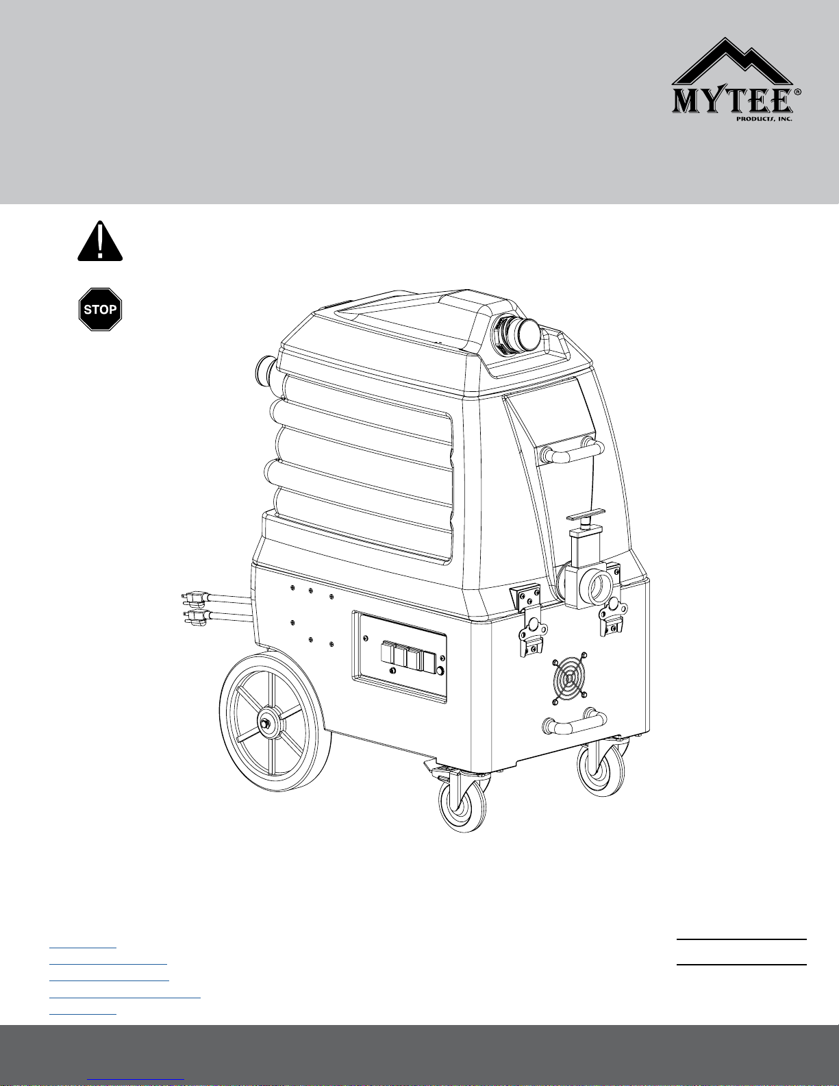
7000S FRONT
1
2
1. Recovery Tank Lid
2. Operating Controls
3. Handles
4. EZ Open Service Latches
5. Drain Valve
6. Vacuum Hose Hook-up
7000S BACK
6
7
5
8
12
4
3
9
10
7. 2” Female Cuff-Lynx™ starter
8. 2” Male Cuff-Lynx™ plug
9. 25’ Power Cord
10. 10” Stair Climbing Wheels
11. 4” Swivel Locking Casters
12. Auto Pump-out Hose Connection
11
7000S ACCESSORIES
WAND INTERCHANGEABLE HEADS
H908 - 2 Piece Aluminum P570 - Scalloped Vacuum Head
Wand Tube
H294 -1.5” x 25’ Vacuum
G200 - Squeegee Vacuum Head
Hose (x2)
H121 - 2”
Cuff Lynx™ Plug
H226 - Drain Elbow
H141 - 2” x 1.5”
Cuff Lynx™ Reducer
FILTERS
G008 - Pack Of Filters
Select either vacuum head and attach to wand. Insert head and
tighten collar.
2
Page 3
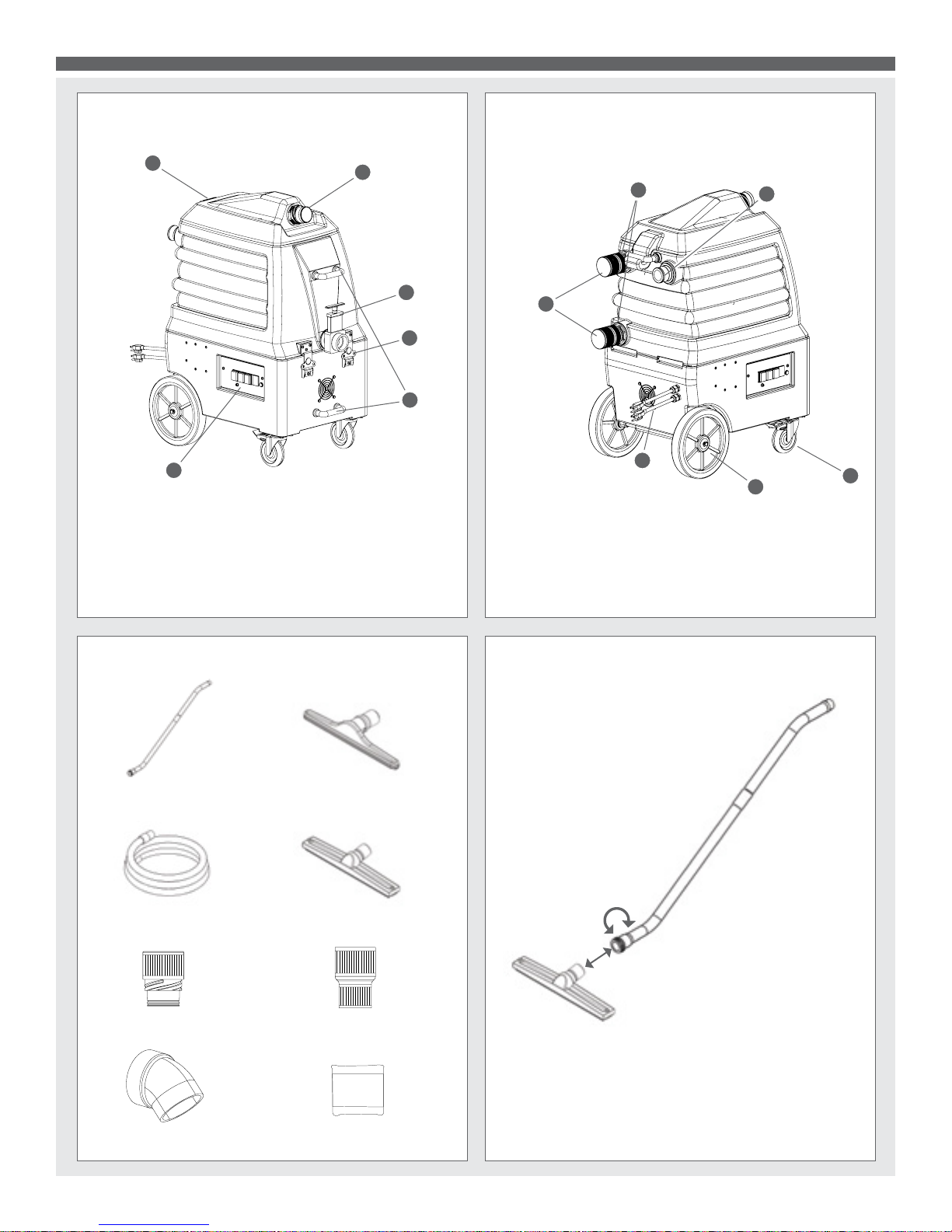
7000S FRONT VACUUM/DEBRIS FILTER HOSE
REV.
OD
HOOK UP
7000S FLOOD HOG™
7000S BACK VACUUM HOSE/AUTO PUMP-OUT
HOOK UP
Attach the hose with the 1.5” Cuff-Lynx™ reducer to the machine.
Attach other end of same hose to wand tube.
7000S DUAL CORDS
Top cord: Powers Vac 1 & Pump.
Bottom cord: Powers Vac 2.
Yellow tag
indicates primary
cord.
Attach the second hose bearing cam lock to the Auto Pump-out
tting. Secure the hose to the tting using the cam lock. Push the
hose cuff onto the tting, making sure the silver ears and rings are
extended forward. Pull the ears down using the rings until connection is tight. Place the end of the hose in a location where dirty
water can drain.
7000S SWITCHES
VACUUM 1 VACUUM 2 PUMP
Plug each power cord into a separate, 20A grounded wall outlet.
Outlets must be on two separate breakers. When the amber
light on the switch plate illuminates, the machine is on separate
circuits (not necessarily 20A circuits). You can identify the primary
cord by the yellow tag.
Dual circuit
indicator light.
Three switches are located on the lower left side of the machine.
To use either vacuum, turn on the Vacuum switch 1 or 2. To use
the pump, turn on the Pump switch.
3
Page 4
REV.
DESCRIPTION
OD
ORIGINAL DRAFT
6
5
4
3
2
7000S FLOOD HOG™
REVISIONS
REV.
DESCRIPTION
DATE
APPROVED
OD
ORIGINAL DRAFT
JFL
D
C
B
7
6
5
4
3
2
1
E
F
REVISIONS
REV.
DESCRIPTION
DATE
APPROVED
OD
ORIGINAL DRAFT
JFL
D
C
B
6
5
4
3
2
1
E
F
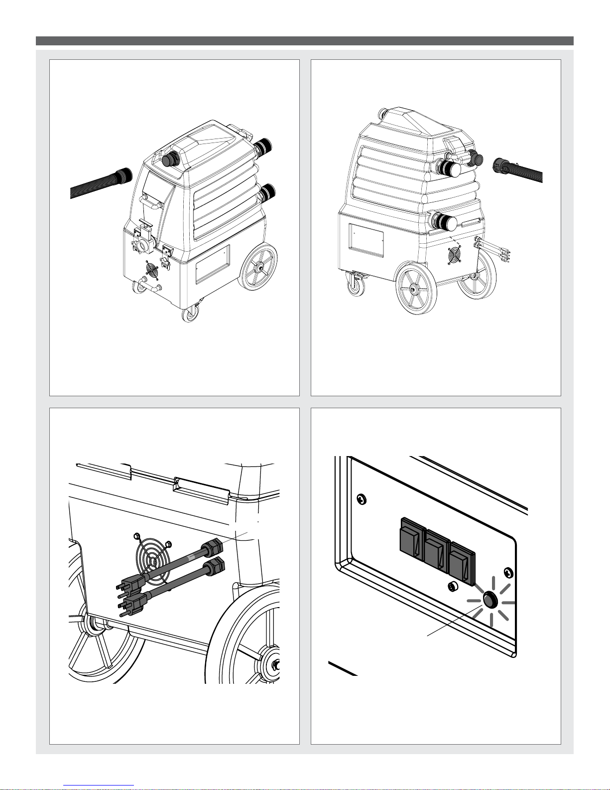
7000S WATER LEVEL CONTROL SWITCHES
Vacuum stack lter
Vacuum water level
control switch
Pump-out water
level control switch
As the water level reaches the pump-out water level control
switch, the pump is activated. Once the water level reaches the
vacuum water level control switch, the vaccum shuts off prevent-
ing the water from going into the vacuum stack, damaging the
vacuum motors. At the top of the vaccum stack, there is a lter.
Clean it weekly.
7000S DRAIN VALVE AND SPOUT
When not using the Auto Pump-out, empty the tank by using the
drain valve on the front of the machine with the included drain
elbow (part # H226).
REAR PLUGS
Cap top plug to use as
a booster and pass-through
extractor.
See page 6.
Cap both plugs
to use as a
ood extractor
Two vacuum plugs are located in the back. The top and bottom rear plugs, depending on how they are capped, allow the Flood Hog™ to
be used as a stand-alone extractor, a ow-through booster connected to another machine, or an in-line pump-out unit. They also seal the
Flood Hog™ vacuum tank.
Cap bottom plug
to use as booster
with pump-out
See page 6.
4
Page 5

REVISIONS
REV.
DESCRIPTION
DATE
OD
ORIGINAL DRAFT
7
6
5
4
3
2
REVISIONS
REV.
DESCRIPTION
DATE
APPROVED
OD
ORIGINAL DRAFT
JFL
D
C
6
5
4
3
2
1
E
F
7000S FLOOD HOG™
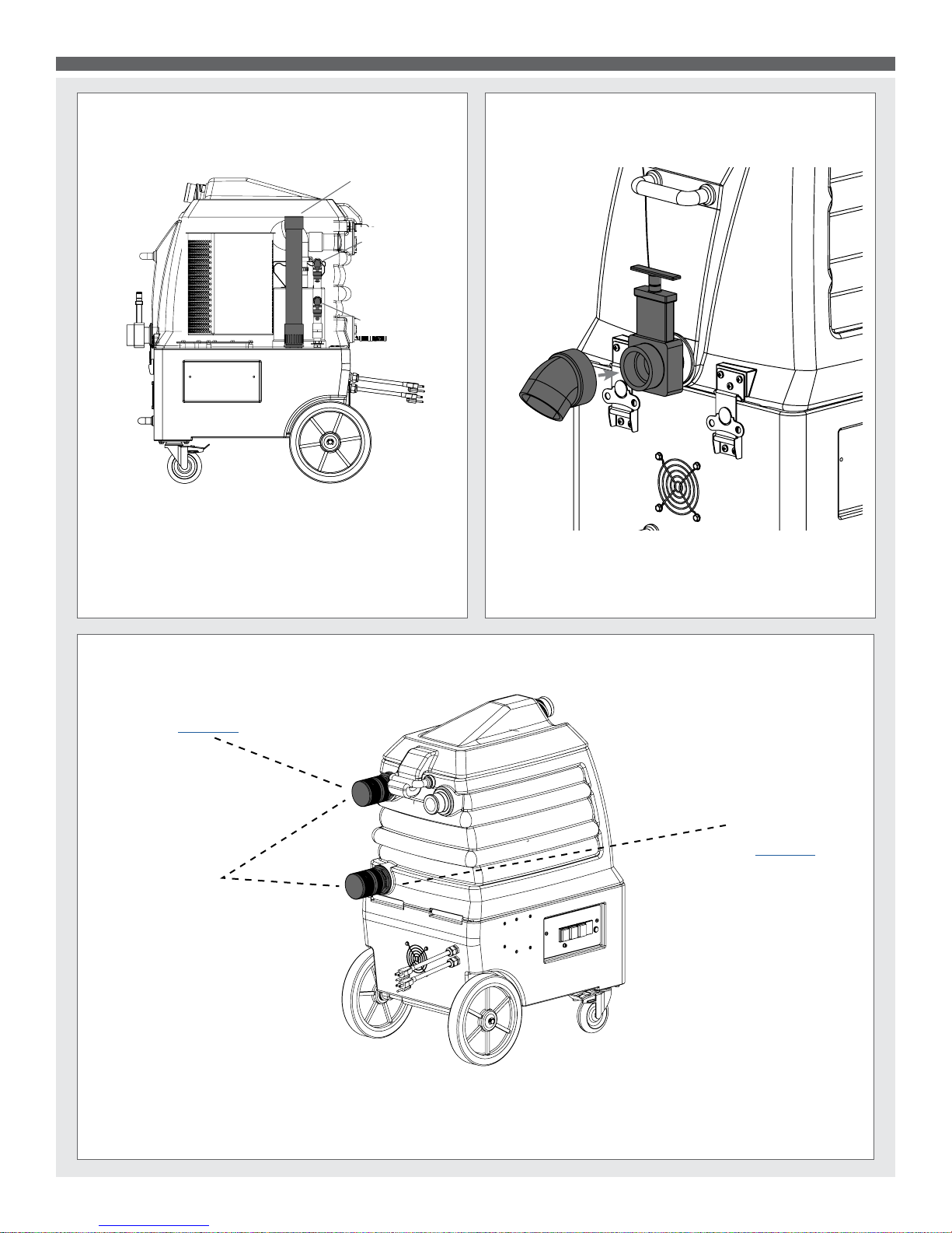
7000S DEBRIS FILTER
7000S LATCHES AND LIFT HANDLE
LATCHES:
Detach: Flip-up latch.
Twist counter clock-
wise for release.
Attach: Place latch.
Twist clockwise
Press latch to secure.
The lter protects the vacuum motor from damaging debris. Keep
it clean by removing the vacuum hose and opening the recovery
tank lid via the latch on the front of the machine. Remove stainless steel basket and gently rinse with water. Dry with a soft cloth.
Replace basket, lid and hose.
LIFT HANDLE: Use lift handle to prevent damage to unit.
DRAIN
Flood Hog™ pumps up to 35 GPM.
7000S FLOOD HOG™ IN USE
FLOODED AREA
5
Page 6

7000S FLOOD HOG™
3. USING THE FLOOD HOG™ AS A BOOSTER WITH AUTO PUMP-OUT
Solution ow
Dirty water recovery
Pump-out system
Base extractor airow
* Wand & extractor not included with Flood Hog™
B
#2
A
C
#1
Drain
The optional pump-out can be used in conjunction with a second, larger extractor (#1), which will be used as a clean water
source. A. Connect a vacuum and solution hose to the larger extractor (#1) and the Flood Hog’s™ (#2) rear top plug. Keep the bottom
rear vacuum plug capped. B. Attach the wand’s vacuum hose to the Flood Hog’s™ front vacuum port and attach the solution hose to the
larger extractor’s QD. C. Connect the Flood Hog’s™ pump-out hose to the Flood Hog™ via the cam-lock tting on the rear of the machine.
Turn on the pump-out switch. Dirty water will be automatically pumped out of the Flood Hog™.
4. USING THE FLOOD HOG™ AS A BOOSTER AND PASS-THROUGH EXTRACTOR
Solution ow
Dirty water recovery
* Wand & extractor not included with Flood Hog™
#2
A
B
#1
The Flood Hog™ (#2) can be used as a pass-through extractor and to boost the airow of a second, larger extractor (#1) by
increasing its CFM by 113. A. To do this, use the larger extractor (#1) as a fresh water source and recovery tank, connect a vacuum hose
to the larger extractor and the Flood Hog’s™ (#2) rear bottom plug. Keep the top rear plug capped. B. To use a wand, attach the wand’s
vacuum hose to the front of the Flood Hog™ and attach the solution hose to larger extractor and to the wand. Clean water will travel from the
larger extractor to the wand to clean the surface, and dirty water will be drawn through the Flood Hog™ into the main extractor’s recovery
tank.
6
Page 7

7000S FLOOD HOG™ PARTS & PRICING
vac hose, 2", black, wire reinforced
vac motor, 3-stage hp, 120V, 145"
bolt, 1/4-20 x 3/4" serrated hex flange, zinc
pump out, 35 gpm, 115v, stainless
vac hose, 1-1/2", black, wire reinforced
barb, 1-1/2" x 1-1/2" fpt, pump out
bushing, brass, 1/2"mpt x 3/8" fpt, hex
elbow, brass, 90 deg, 1/4"mpt x 1/4" fpt
level switch, vacuum shut-off, rear threads
washer, 11/16"id x 1-1/2"od x .075, s/s
vac hose, 1-1/2", black, wire reinforced
caster, 4", black hub & gray tread
screw, 10-32 x 1/2" phil pan head, s/s
F
1
2
E
D
C
B
A
REV
OD
PRODUCTS, INC.
858-679-1191
mytee
TITLE:
DATE
NAME
V. LaBarbera
CHECKED
DRAWN
COMMENTS:
7000S
DWG. NO.
Flood Hog (2014)
C
SIZE
PROPRIETARY AND CONFIDENTIAL
THE INFORMATION CONTAINED IN THIS
DRAWING IS THE SOLE PROPERTY OF
MYTEE PRODUCTS, INC. ANY
REPRODUCTION IN PART OR AS A WHOLE
WITHOUT THE WRITTEN PERMISSION OF
MYTEE PRODUCTS, INC. IS
SHEET 1 OF 3
1
DO NOT
SCALE DRAWING
SCALE: 1:32
2
PROHIBITED.
3
4
5
6
MSRP
$0.99 ea
$6.99 ea
$1.99 ea
$0.99 ea
1
1
2
QTY.
DESCRIPTION
6
washer, 8 flat, s/s
bumper, 7/8" x 1/4" head
plate, switch, RL1200, 7000DX
screw, 10-32 x 3/4, phil flat full thread
H612
H641
H186
NO.
G068
63
64
65
$96.99
$3.99 ea
$21.99 ea
1
1
1
66
$1.49 ea
5
PART NO.
ITEM
MSRP
QTY.
$4.49 ea
$1.99 ea
$62.99 ea
$133.99 ea
1
1
controller, circuit light
controller, water level, dual pump or vac
E564
E370
67
68
$8.99 ft
$148.99 ea
1
2
$3.19 ea
$114.99 ea
1
Level Switch Control
$11.49 ea
$135.99 ea
2
2
2
2
1
bracket, hinge
base, breeze
nut, lock, 1/2" steel
fitting, strain relief, cord
power cord, pigtail, 30", 12/3, black
E628
69
12 $0.99 ea
H487
H221
70
71
$4.99 ea
$8.99 ea
6
2
E550
H220
72
73
$0.99 ea
$14.99 ea
6
2
P696
74
$14.99 ea
1
$6.99 ea
$1.99 ea
$34.99 ea
1
3
4
$0.99 ea
2
$64.99 ea
$193.99 ea
$429.99 ea
1
1
1
$4.99 ft
$5.99 ea
$24.49 ea
2
1
1
$4.99 ft
$1.99 ea
1
1
$4.99 ea
$5.00 ea
1
1
$4.99/ft
$4.99 ea
1
1
$3.99 ea
$19.99 ea
$21.99 ea
1
1
2
$3.99 ea
$2.00 ea
2
1
$2.49 ea
$3.19 ea
4
2
$4.49 ea
$13.99 ea
2
2
$1.99 ea
$0.99 ea
1
1
$1.99 ft
$3.99 ea
1
1
$1.99 ft
$0.99 ea
1
1
$4.99 ft
$5.99 ea
1
1
$0.99 ea
$4.99 ea
1
2
$0.99 ea
$9.99 ea
$35.49 ea
2
4
1
$0.99 ea
$0.99 ea
$19.49 ea
2
8
8
$0.99 ea
$2.99 ea
3
8
$13.99 ea
2
32 $0.99 ea
15 $0.99 ea
$9.99 ea
$1.99 ea
1
1
$0.99 ea
$13.99 ea
3
1
3
4
5
6
7
DESCRIPTION
8
PART NO.
ITEM
lid, 7000S
gasket, vac lid, 7000S
clamp, hose, 2-1/4 dia
Cuff-Lynx, 2" m cuff x 2" mpt
P740
H135
H217
G106
1
2
3
NO.
4
F
vac support, 3 stage, 4-1/16"
H768
H501
C302A
PH628-10
5
6
7
8
valve, drain, 2"
gasket, vacuum motor
plate, dual manifold, 9" x 13"
bolt, 1/4-20 x 3/4" hex head, s/s
manifold, single vac, no gasket
P735
H202
H253
G004
9
G072
10
11
12
13
flood hog (2014), vac tank
handle, aluminim grip, black
washer, 1/4"id x 1"od, flat, s/s
washer, buna 1-1/8" od x 3/16" id
P741
H485
H211
G052
14
15
16
17
E
filter basket, flood hog
H023
C384
18
19
pipe, pvc, 1-1/2"
cuff, hose, 1-1/2 x 1-1/2, wire
swing check valve, pump out
P686
H300
G003 filter, foam, 2" x .50" o.d.
PH633-1
PH627-7
20
22
23
24
21
pipe, pvc, 1-1/2"
adapter, 1.5" pvc, fslip x fslip
screen, mesh filter, 1-1/2" dia
P502
G097
PH633-12
25
26
27
D
cuff-lynx, 2" plug
adapter, pvc, 1-1/2" fms x fmpt
H244
H396
28
29
elbow, pvc 1/2" fmt x 1/2" fms
Cuff-Lynx, 2" mpt x 2" female cuff
cam & grovve fitting 1-1/2", male
B210
P680
H207
H121
H124
30
31
32
34
33
7
pipe, pvc, 1/2" x 20'
pipe, pvc, 1/2" x 20'
adapter, pvc, 1/2" fpt x s
nipple, brass, 3/8" x close
bushing, brass, 3/8"mpt x 1/4"
E373
B105
B216
B103
35
36
C
P679
H299
37
38
39
40
inlet, pvc, 1-1/2", gray
TEE 1/2" FSlip x 1/2" FSlip x 1/2" FPT
P575
H229
P677-2
P677-2.5
41
PH627-15
42
43
44
45
Part prices are subject to change.Order parts at: www.mytee.com
wheel, 10"
washer, 1/4" flat, s/s
exhaust boot, plastisol
G059
46
B
axle, 18.03" x .50" dia
c-clip, 12mm, external
washer, axle, cut 1/2" id
H042
H392
H254
H371
47
48
49
50
guard, cooling fan, wire
bolt, 1/4-20 x 1" hex head, s/s
H668
H342
H210
H296
51
52
53
54
7
plug
latch, front
nut, kep, #10-32 zinc
switch, rocker, 2 position
light, indicator, 125v (amber)
screw, 10 x 5/8" hex head, zinc
H343
H486
H230
H273
55
56
57
58
A
screw, 10-32 x 1/2" SHCS, alloy
8
E515
H389
E512B
P967A
59
60
61
62
Page 8

7000S FLOOD HOG™ PARTS & PRICING
F
1
2
3
4
24
23
E
73
D
74
72
71
57
57
70
69
68
67
58
66
65
64
58
63
62
61
60
58
57
59
57
31
30
33
32
29
26
27
25
28
C
B
47
48
49
50
51
A
REV
OD
PRODUCTS, INC.
858-679-1191
mytee
TITLE:
DATE
NAME
V. LaBarbera
CHECKED
DRAWN
COMMENTS:
7000S
DWG. NO.
Flood Hog (2014)
C
SIZE
PROPRIETARY AND CONFIDENTIAL
THE INFORMATION CONTAINED IN THIS
DRAWING IS THE SOLE PROPERTY OF
MYTEE PRODUCTS, INC. ANY
REPRODUCTION IN PART OR AS A WHOLE
WITHOUT THE WRITTEN PERMISSION OF
MYTEE PRODUCTS, INC. IS
SHEET 2 OF 3
1
DO NOT
SCALE DRAWING
SCALE: 1:32
2
PROHIBITED.
52
53
54
56
55
3
37
36
35
34
43
39
34
38
34
40
42
41
46
45
22
44
4
4
5
5
22
5
6
21
20
19
18
17
7
6
7
3
15
13
14
12
11
9
8
10
7
6
7
1
8
2
8
F
E
D
C
B
A
8
Page 9

7000S FLOOD HOG™ WIRING DIAGRAM
3/12/2015
E-515
G
E-515
VAC 2
C-302A
L2L1
E-515
Ground to
metal plate
G
Out
Pump
C-384
L2L1
E-370
Float
Switch
7000S Wire Schematic
G
L1
Cord 1
L2
L1a
E-628
G
VAC 1
C-302A
E-512
L1L2
Float
Switch
G
L2a
light
L1b
L2b
L1
Cord 2
L2
E-564
9
Page 10

GENERAL INFORMATION
Dear Customer:
Congratulations on the purchase of your new 7000S Flood Hog™. As you
are already aware, the scene of the equipment world is becoming more high tech,
and we at Mytee Products Inc. strive to keep you on the cutting edge with superior
quality and technology.
Keep in mind that the 7000S Flood Hog™ is a machine, so neglect or abuse will
cause unnecessary damage and void the warranty. However with simple maintenance the Flood Hog™ will give quality performance for many years to come.
If warranty questions arise, please consult your user manual or get in touch with
your distributor. If you have questions about maintenance, replacing parts or
ordering parts, please call an authorized Mytee Products Inc. Service Center.
To see an updated list, visit our website at www.mytee.com
Before you begin cleaning, please read your manual thoroughly.
Sincerely,
Mytee Customer Care Dept.
Grounding Instructions
This machine must be grounded. If it should malfunction or break down, grounding
provides a path of least resistance for electrical shock. This machine is equipped
with a cord having an equipment-grounding conductor and grounding plug. The plug
must be plugged into an appropriate outlet that is properly installed in accordance
with all local code and ordinances. Do not remove ground pin; if missing, replace
plug before use.
Improper connection of the equipment-grounding conductor can result in a risk of
electric shock. Check with a qualied electrician or service person if you are in doubt
as to whether the outlet is properly grounded. Do not modify the plug provided with
the machine. If it will not t the outlet, have a proper outlet installed by a qualied
electrician.
This appliance is for use on a nominal 120-volt circuit, and has a grounding plug
that looks like the plug illustrated in Figure 1 below. A temporary adapter illustrated
in Figures 2 and 3 may be used~to connect this plug to a 2-pole receptacle as
shown in Figure 2 if a properly grounded outlet is not available. The temporary
adapter should be used only until a properly grounded outlet (Figure 1) can be
installed by a qualied electrician. The green colored rigid ear, tab or the like
extending from the adapter must be connected to a permanent ground such as a
properly grounded outlet box cover. Whenever the adapter is used, it must be held
in place by a metal screw. Grounding adapters are not approved for use in Canada.
Replace the plug if the grounding pin is damaged or broken.
The green (or green-yellow) wire in the cord is the grounding wire. When replacing
a plug, this wire must be attached to the grounding pin only.
DO NOT use extension cords.
Please Note for America use only
Grounding Pin
Figure 1
Grounded Outlet
Metal
Screw
Grounded Outlet Box
Figure 2 Figure 3
Adapter
Tab for Grounding
Screw
Parts and Service
Repairs, when required, should be performed by Mytee service personnel or Mytee
authorized Service Center using Mytee original replacement parts and accessories.
Call Mytee for repair parts or service. Please specify the Model and Serial Number
when discussing your machine.
Name Plate
The Model and Serial Number of your machine are shown on the Nameplate on the
back panel of the machine. This information is needed when ordering repair parts
for the machine. Use the space provided on the front cover to note the Model and
Serial Number of your machine for future reference.
Unpacking the Machine
When the machine is delivered, carefully inspect the shipping carton and the
machine for damage. If damage is evident, save the shipping carton so that it can
be inspected by the carrier that delivered it. Contact the carrier immediately to le a
freight damage claim.
Caution and Warnings
Symbols
Mytee uses the symbols below to signal potentially dangerous conditions. Always
read this information carefully and take the necessary steps to protect personnel
and property.
Is used to warn of immediate hazards that will cause severe personal injury or death.
Is used to call attention to a situation that could cause severe personal injury.
Is used to call attention to a situation that could cause minor personal injury or
damage to the machine or other property. When using an electrical appliance, basic
precautions should always be followed, including the following: Read all instructions
before using this machine. This product is intended for commercial use only.
To reduce the risk of re, electrical shock, or injury:
1. Read all instructions before using equipment.
2. Use only as described in this manual. Use only manufacturer’s recommended
attachments.
3. Always unplug power cord from electrical outlet before attempting any adjustments
or repairs.
4. Do not unplug by pulling on cord. To unplug, grasp the plug, not the cord.
5. Do not pull by cord. Do not close a door on cord or pull cord around sharp edges
or corners.
6. Do not run appliance over cord. Keep cord away from heated surfaces.
7. Do not use with damaged cord or plug. If cord is damaged, repair immediately.
8. Always unplug or disconnect the appliance from power supply when not in use.
9. Do not allow to be used as a toy. Close attention is necessary when used by or
near children.
10. Do not use in areas where ammable or combustible material may be present.
11. Do not leave the unit exposed to harsh weather elements. Temperatures below
freezing may damage components and void warranty.
12. Use only the appropriate handles to move and lift unit. Do not use any other parts
of this machine for this purpose.
13. Keep hair, loose clothing, ngers, and all parts of the body away from all
openings and moving parts.
14. Use extra care when cleaning on stairs.
15. To reduce the risk of re or electric shock, do not use this machine with a solid-
state speed control device.
16. The voltage and frequency indicated on the name plate must correspond to the
wall receptacle supply voltage.
17. When cleaning and servicing the machine, local or national regulations may apply
to the safe disposal of liquids which may contain: chemicals, grease, oil, acid,
alkalines, or other dangerous liquids.
18. Do not leave operating unattended.
Pre-Operation
1. Remove furniture and other items from the area you are going to treat.
2. Make sure debris lter is clear and electrical cord is in good repair.
3. Make sure a 20A grounded wall outlet is available for cord. Do not use
extension cord.
Operation
1. In front, attach one end of the rst vacuum hose to a wand (using scalloped or
squeegee vacuum head), the other end to the Cuff-Lynx™ hose connection on the
front of the machine.
2. The debris lter inside the machine protects the vacuum motor from damaging
debris. Keep it clean by removing vacuum hose and turning the top latch counter-
clockwise and opening the lid. Remove stainless steel basket and gently rinse with
water. Dry with a soft cloth. Replace basket, lid and hose.
3. In back, attach the second vacuum hose bearing cam lock to the Auto Pump-out
tting. Secure the hose to the tting using the cam lock. Push the hose cuff onto
the tting, making sure the silver ears and rings are extended forward. Pull the ears
10
Page 11

down using the rings until connection is tight. Place the end of the hose in a location
where dirty water can drain.
4. Two power cords are located in the back of the machine. To power Vacuum 1 and
Pump, plug in the top cord. To power the Vacuum 2, plug in the bottom cord. Plug
each of the two power cords into two separate, 20A grounded wall outlets. Do not
use extension cords.
5. Three switches are located on the lower left side of the machine. To use the
vacuum 1, turn on the Vacuum 1 switch. To use Vacuum 2, turn on the Vacuum 2
switch. To use the pump, turn on the Pump switch.
6. Place wand over ooded area and begin extracting.
7. If pump must be accessed during extraction, use the recovery tank lid on top of
the machine. Pull the lever up and turn counter clockwise until it faces the side of the
machine. Pull up and take the lid off. Use reverse procedure to replace.
8. When the job is nished, turn off switches and unplug power cords. Remove
hoses.
After Use
1. Unplug.
2. Inspect hoses and replace if damaged.
3. Inspect lter and clean.
4. Open recovery tank to promote air circulation
5. Make sure machine and hoses are completely drained and dry.
6. Store the machine in a clean, dry place.
Maintenance Schedule
Maintenance item Daily Once a week
Clean and inspect Tanks
Clean and inspect Hoses
Inspect lters
Check electrical cord
Clean machine with all purpose cleaner and cloth
Inspect vacuum hoses for holes and loose cuffs
Lubricate wheels with water-resistant oil
Inspect machine for water leaks and loose hardware
x
x
x
x
x
x
x
x
Trouble Shooting
There is no power.
1. Plug machine in proper outlet.
2. Check circuit breaker; reset circuit breaker, other items should not run on the
same circuit as machine. Outlet must be a 20-amp circuit. For 7000S models, two
separate 20-amp circuits are required.
Pump does not work properly.
1. Check pump wire. May need to reconnect wire.
2. Switch plate switch may need to be replaced.
3. If pump motor brushes are worn, replace pump.
4. Float switch obstructed. Clean.
Vacuum motor does not work properly.
1. Check that hose is tightly connected.
2. Close drain hose valve completely.
3. Secure the vacuum tank tightly.
4. If water is coming out of vacuum motor, use a low foaming detergent.
FAQs
Q: How much does the 7000S weigh and what are the shipping dimensions?
A. 7000S weighs 124 pounds - Box dimensions are 20” x 30” x 48”. Must ship motor
freight.
GENERAL INFORMATION
Q: What comes standard with the 7000S?
A: The 7000S comes with two 25’ vacuum hoses (H294), a wand (H908), a vacuum
head (P570), a squeegee vacuum head (G200) a 2” x 1.5” Cuff Lynx™ (H141), two
2” Cuff-Lynx™ plugs (H121), and pack of lters (G008).
Q: Where do I plug the machine in?
A: Plug each power cord into a separate, 20A grounded wall outlet. Outlets must
be on two separate breakers. When the amber light on the switch plate illuminates,
the machine is on separate circuits (not necessarily 20A circuits). You can identify the
primary cord by the yellow tag.
Q: Is there anything I can do to increase the expected life of my machine?
A: Running the vacuum motors with the tank empty and lid off will allow excess
moisture in the vacs to dry off.
11
Page 12

NOTES
Mytee Products Inc.
13655 Stowe Dr.
Poway, CA 92064
www.mytee.com
FX 858.679.7814
© 2015 Mytee Products Inc.
Printed in the U.S.A.
12
 Loading...