

Page 1
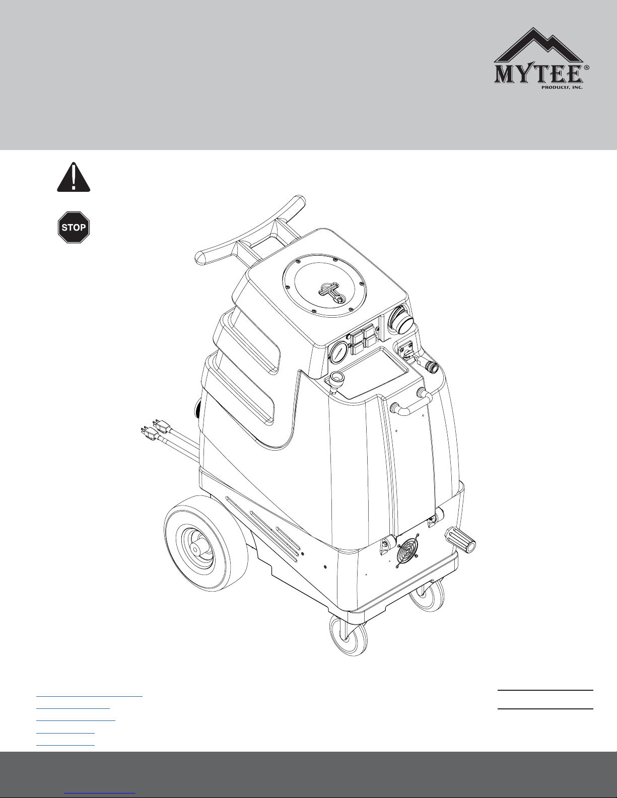
Instructions for
1000DX-200, 1001DX-200,
1003DX, 1005DX Speedster
Please read before use.
Register your product
at http://www.mytee.
com/support/register
®
General Information p.2
1000DX-200 p.5
1001DX-200 p.11
1003DX p.17
1005DX p.23
Model #
Serial #
Form # ADP-Speedster
5-17
13655 Stowe Dr. Poway, CA 92064
1
Page 2
GENERAL INFORMATION
Dear Customer:
Congratulations on the purchase of your new Speedster® Extractor. As you
are already aware, the scene of the equipment world is becoming more
high tech, and we at Mytee Products Inc. strive to keep you on the cutting
edge with superior quality and technology.
Keep in mind that the Speedster® Extractor is a machine, so neglect or
abuse will cause unnecessary damage and void the warranty. However
with simple maintenance the Speedster® will give quality performance for
many years to come.
If warranty questions arise, please consult user manual or get in touch with
your distributor. If you have questions about maintenance, replacing parts
or ordering parts, please call an authorized Mytee Products Inc. Service
Center. To see an updated list, visit our website at www.mytee.com
Before you begin using, please read your manual thoroughly.
Sincerely,
Mytee Customer Care Dept.
Grounding Instructions
This machine must be grounded. If it should malfunction or breakdown,
grounding provides a path of least resistance for electrical shock. This machine is equipped with a cord having an equipment-grounding conductor
and grounding plug. The plug must be plugged into an appropriate outlet
that is properly installed in accordance with all local code and ordinances.
Do not remove ground pin; if missing, replace plug before use.
Improper connection of the equipment-grounding conductor can result in a
risk of electric shock. Check with a qualied electrician or service person
if you are in doubt as to whether the outlet is properly grounded. Do not
modify the plug provided with the machine. If it will not t the outlet, have a
proper outlet installed by a qualied electrician.
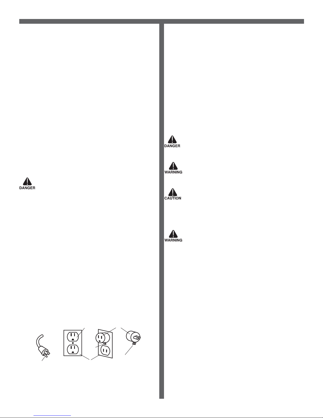
This appliance is for use on a nominal 120-volt circuit, and has a grounding plug that looks like the plug illustrated in Figure 1 below. A temporary
adapter illustrated in Figures 2 and 3 may be used~to connect this plug to
a 2-pole receptacle as shown in Figure 2 if a properly grounded outlet is
not available. The temporary adapter should be used only until a properly
grounded outlet (Figure 1) can be installed by a qualied electrician. The
green colored rigid ear, tab or the like extending from the adapter must be
connected to a permanent ground such as a properly grounded outlet box
cover. Whenever the adapter is used, it must be held in place by a metal
screw. Grounding adapters are not approved for use in Canada.
Replace the plug if the grounding pin is damaged or broken.
The Green (or GreenYellow) wire in the cord is the grounding wire. When
replacing a plug, this wire must be attached to the grounding pin only.
DO NOT use extension cords.
Please Note for America use only
Grounding Pin
Figure 1
Grounded Outlet
Metal
Screw
Grounded Outlet Box
Figure 2 Figure 3
Adapter
Tab for Grounding
Screw
Parts and Service
Repairs, when required, should be performed by Mytee service personnel or Mytee authorized Service Center using Mytee original replacement
parts and accessories. Call Mytee for repair parts or service. Please
specify the Model and Serial Number when discussing your machine.
Name Plate
The Model and Serial Number of your machine are shown on the name
plate located on the inside of the machine. This information is needed
when ordering repair parts for the machine. Use the space provided on
the front cover to note the Model and Serial Number of your machine for
future reference.
Unpacking the Machine
When the machine is delivered, carefully inspect the shipping carton and
the machine for damage. If damage is evident, save the shipping carton so
that it can be inspected by the carrier that delivered it. Contact the carrier
immediately to le a freight damage claim.
Caution and Warnings
Symbols
Mytee uses the symbols below to signal potentially dangerous conditions.
Always read this information carefully and take the necessary steps to
protect personnel and property.
Is used to warn of immediate hazards that will cause severe personal
injury or death.
Is used to call attention to a situation that could cause severe personal
injury.
Is used to call attention to a situation that could cause minor personal
injury or damage to the machine or other property. When using an electrical appliance, basic precautions should always be followed, including the
following: Read all instructions before using this machine. This product is
intended for commercial use only.
To reduce the risk of re, electrical shock, or injury:
1. Read all instructions before using equipment.
2. Use only as described in this manual. Use only manufacturer’s recommended attachments.
3. Always unplug power cord from electrical outlet before attempting any
adjustments or repairs.
4. Do not unplug by pulling on cord. To unplug, grasp the plug, not the
cord.
5. Do not pull or carry by cord. Do not close a door on cord or pull cord
around sharp edges or corners.
6. Do not run appliance over cord. Keep cord away from heated surfaces.
7. Do not use with damaged cord or plug. If cord is damaged, repair immediately.
8. Do not use outdoors or on wet surfaces and or standing water.
9. Always unplug or disconnect the appliance from power supply when not
in use.
10. Do not allow to be used as a toy. Close attention is necessary when
used by or near children.
11. Do not use in areas where ammable or combustible material may be
present.
12. Do not leave the unit exposed to harsh weather elements. Temperatures below freezing may damage components and void warranty.
13. Use only the appropriate handles to move and lift unit. Do not use any
other parts of this machine for this purpose.
14. Keep hair, loose clothing, ngers, and all parts of the body away from
all openings and moving parts.
15. Use extra care when using on stairs.
16. To reduce the risk of re or electric shock, do not use this machine with
a solid-state speed control device.
2
Page 3
GENERAL INFORMATION
17. The voltage and frequency indicated on the name plate must correspond to the wall receptacle supply voltage.
18. When cleaning and servicing the machine, local or national regulations
may apply to the safe disposal of liquids which may contain: chemicals,
grease, oil, acid, alkalines, or other dangerous liquids.
19. Do not leave operating unattended.
Preparation
1. Remove furniture and other items from the area you are going to clean.
2. Vacuum carpet and upholstery, and remove debris.
3. Protect cabinets, walls and painted surfaces with drop cloths or plastic.
4. Inspect power cords for damages.
Operating Instructions
1. Fill the solution tank.
2. Attach one end of a solution hose to a wand or other tool, the other end
to the Speedster’s® front quick disconnect.
3. Attach one end of a vacuum hose to the tool, the other end to the
Speedster’s® Cuff-Lynx™ vacuum hose port.
4. Plug in power cords.
• 1000DX-200 models – Plug single cord into single, 20A grounded wall
outlet.
• 1001DX-200 models – Using two separate circuits/breakers, plug the left
power cord into 20A grounded wall outlet to turn on Vac 2 and Heater 2.
Plug the right power cord into separate 20A grounded wall outlet to turn on
Vac 1, Heater 1 and Pump.
• 1003DX models – Using two separate circuits/breakers, plug the left
power cord into 20A grounded wall outlet to turn on Vac 2 and Heater 2.
Plug the right power cord into separate 20A grounded wall outlet to turn on
Vac 1, Heater 1 and Pump.
• 1005DX models – Using two separate circuits/breakers, plug the left
power cord into 20A grounded wall outlet to turn on Vac 2. Plug the right
power cord into separate 20A grounded wall outlet to turn on Vac 1 and
Pump.
The amber light indicator on the switch plate will illuminate brightly when
cords are plugged into two separate circuits. Do not use extension cords
longer than 50 feet.
5. Turn on switches.
• 1000DX-200, 1005DX models – Turn on Vac 1, Vac 2 and Pump
switches.
• 1001DX-200 and 1003DX – Turn on Vac 1, Vac 2 and Pump switches.
Turn on Heater switch if heat is being used. Wait several minutes for water
to heat. Heater switch has three positions: Off (middle); 1,000 watts using
one heater (left); and 2,000 watts using two heaters (right). Red lights on
panel display indicate watts selected: one light = 1,000 watts; two lights =
2,000 watts; no lights = heaters are off.
6. 1003DX and 1005DX models – Prime Valve and Pressure Regulator
are located on the lower front of the extractor. To prime the pump, turn the
valve to the Prime position for 30 seconds, then turn horizontally to the
Run position. Turn the Pressure Regulator to the left to decrease the water
pressure. Turn to the right to increase water pressure. Level will be visible
on the pressure gauge. Monitor while adjusting, using Pressure Gauge on
Switch Panel.
7. Begin cleaning. Make two dry passes to every wet pass. Work away
from cords to avoid damage. To clean heavily soiled areas, repeat cleaning from a different direction.
8. Use a foam control solution in the recovery tank to prevent motor damage and check for foam build-up in recovery and solution tanks.
9. Empty the recovery tank whenever you need to rell the solution tank.
Attach the 45˚ drain elbow to the drain spout in back. Lift up the dump
valve and empty tank.
10. To relieve water pressure from the solution hose before disconnecting
it, squeeze the tool’s trigger ve seconds after turning the power switches
off.
11. Once machine is off, unplug power cords. Remove solution and
vacuum hoses. Empty the recovery tank.
12. 1003DX and 1005DX models – Water remaining in the solution tank
can be emptied by turning the Prime Valve to the right to move water into
the recovery tank. Empty recovery tank.
Please note: Your pump features a pressure switch, to protect vital
components. A minimum spray jet size of 02 needed for use with this
pump. Using a jet size smaller than this can cause back-pressure to
the pump, leading to an over-heat condition. Make sure that your tool
has a jet size of 02 or larger prior to use.
After Use
1. Before storing machine, drain, rinse and dry tanks and vacuum hose of
water and solution.
2. Store in a dry are in the upright position.
3. Open recover tank cover to promote air circulation.
4. Store indoors in a dry area. If storing in freezing temperatures, make
sure the machine and solution system are completely drained and dry.
Maintenance Schedule
Latches are located in back to open tank for internal maintenance. To
keep machine in good working condition, follow machine’s daily and
weekly maintenance procedures. Check valves and relief valves should be
replaced annually.
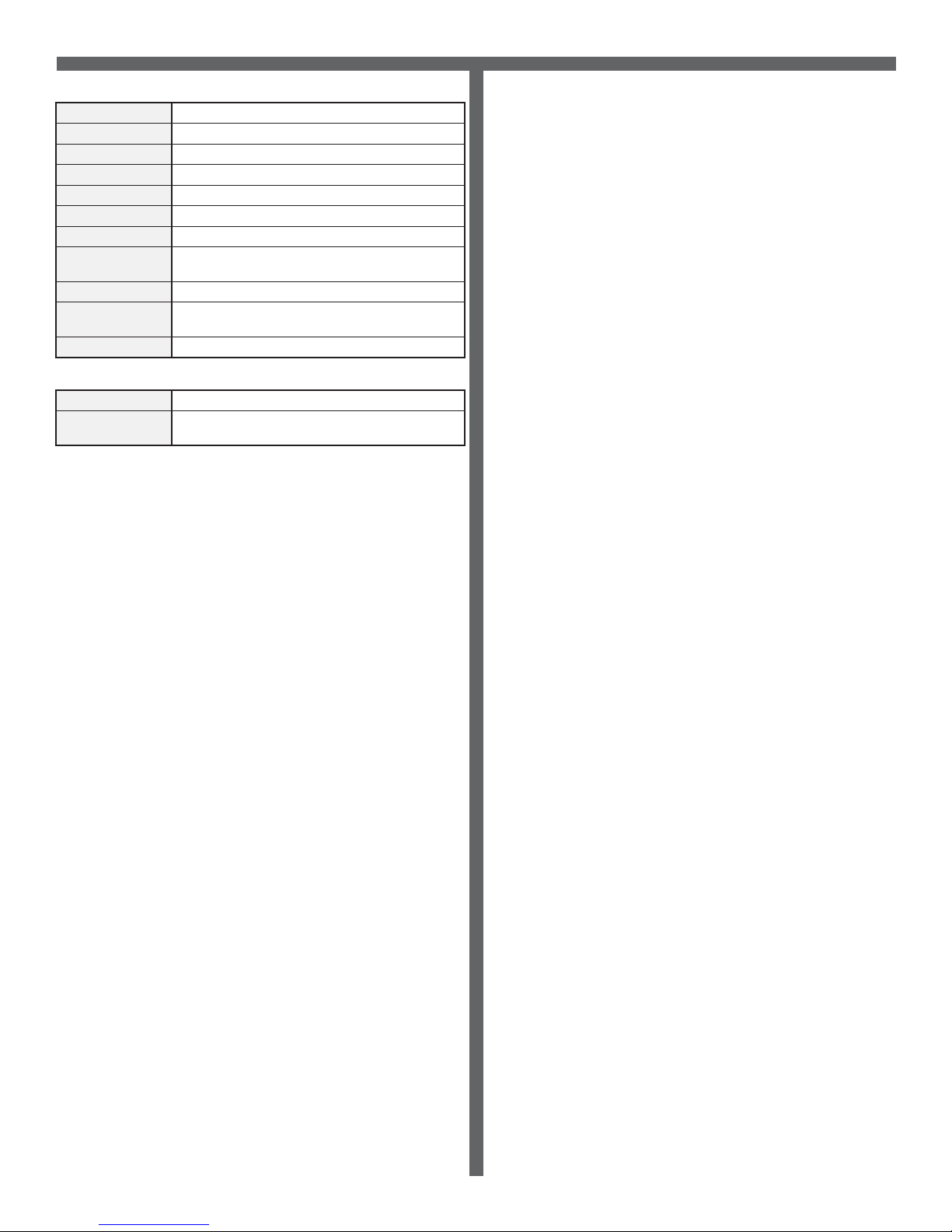
Maintenance item Daily Once a week
Clean and inspect tanks.
Clean and inspect hoses.
Check and clean internal lters by twisting
off, rinsing with clean water and replacing.
Check power supply cable.
Clean machine with all-purpose cleaner
and cloth.
Check spray nozzles.
Flush solution system with Mytee
Maintainer.
Remove and oat shut-off screen from
tank and clean. Simply pull off.
Inspect vacuum hoses for holes and loose
cuffs.
Inspect spray pattern for clogging. If
clogged, remove spray tips and soak them
in a recommended liquid neutralizer for
up to six hours. To remove spray tip, twist
spray tip body counter-clockwise.
Lubricate wheels with water resistant oil.
Inspect machine for water leaks and loose
hardware.
®
System
x
x
x
x
x
x
x
x
x
x
x
x
Troubleshooting
There is no power.
• Plug the machine into proper outlets.
• If using two cords, make sure that each is plugged into a separate circuit.
• Check the circuit breaker. Other devices should not run on the same
circuit as the extractor. Use a 20 amp outlet.
Pump does not work properly.
• Make sure solution disconnects are properly connected.
• Check solution tank. May be empty.
• The system could be vapor locked, which results from activating the
heater before the pump. Release pent-up pressure by removing extractor
outlet disconnect, or by depressing the disconnect inner poppet valve using a dull plastic object (such as a pen). Resume operation using proper
technique outlined in this manual.
• Jets may be clogged. Remove jet and ush clean.
• Filters clogged. Remove lters, clean, and ush with water.
• Heater may be partially blocked. Flush system with System Maintainer.
• Inspect heater check valve (if machine is equipped with heater). Replace
if necessary.
• Check pump wire(s). Reconnect or replace when necessary.
• Check panel switch. Replace if faulty.
• Worn pump motor brushes (if equipped). Replace pump motor.
3
Page 4
GENERAL INFORMATION
• Refer to relevant in-depth troubleshooting information in “Technical Sup-
port” section of Mytee website, for specic pump type.
http://www.mytee.com/support/.
Heater does not function (if equipped).
• Check manual sensor on heater (reset by pressing button on sensor).
Replace if non-functional.
• Check panel switch. Replace if necessary.
• Check automatic sensor (check for continuity when cool). Replace if
found faulty.
• Heating element may have failed. Replace. Check using amp meter
when heater is engaged independently.
• Reconnect heater wire if disconnected.
• Refer to relevant in-depth troubleshooting information in “Technical Support” section of Mytee website. http://www.mytee.com/support/.
Vacuum motor does not function properly.
• Check that all vacuum hoses are tightly connected.
• Close recovery tank drain valve completely.
• Secure the vacuum tank lid tightly.
• Hose/tool blockage or leakage. Repair or unblock the tool or hose.
• Secure the vacuum tank lid tightly.
• Grinding noise from blower indicates impeller failure from debris, dry
vacuuming, or over lling/foaming. Replace vacuum motor.
• Worn motor brushes. Replace vacuum motor.
Vacuum motor exhaust is venting water or foam.
• Check for recovery tank foaming. Use defoamer. Never use a foaming
detergent to clean.
• Make sure recovery tank is not overlling. Make sure ball oat mechanism is functioning.
• Vacuum port boot may be turned in improper direction (if equipped).
Rotate to direct ow away from vacuum stack.
THE FOLLOWING APPLIES TO BRAND NEW MACHINES:
Pump system will not ow water (heated units with diaphragm
pump).
• The system could be vapor locked, which results from activating the
heater before the pump. Release pent-up pressure by removing extractor
outlet disconnect, or by depressing the disconnect inner poppet valve using a dull plastic object (such as a pen). Resume operation using proper
technique outlined in this manual.
• Hanging heater check valve. Remove hose to heater check valve and
manually manipulate the internal valve poppet ball with a straightened
paper clip. Replace hose to test. Replace faulty check valve.
Unit is tripping circuit breakers.
• Ensure that only 20 amp circuits are being used.
• Use only a cord approved for the machine.
• Do not add any extension cords to those cords supplied for use with
extractor.
• Dual cord units must be connected to separate circuits, not just separate
outlets.
• Faulty component may be drawing excessive amperage. Check each
component separately with an amp meter.
• Faulty circuit breaker at site (use another outlet).
1000DX-200 Specications
Solution Tank 10 gallons
Recovery Tank 9 gallons
Vacuum Dual 3-stage low amp
CFM 200
Water Lift 130”
Pump PSI 220
Pump GPM 1.3 5
Power
Consumption
20 amps @ 115V 60Hz
Machine Weight 87 lbs.
Machine
Dimensions
Power Cord 50’ 12/3 extension cord
28” x 18.5” x 39”
1000DX-200 230V Conguration Information
Model Number 1000DX-200-230
Power
Consumption
10 amps @ 230V 60Hz/50Hz
1001DX-200 Specications
Solution Tank 10 gallons
Recovery Tank 9 gallons
Vacuum Dual 3-stage low amp
CFM 200
Water Lift 130”
Pump PSI 220
Pump GPM 1.3 5
Heater 2,000W - 210° ma x.
Power
Consumption
Machine Weight 120 lbs.
Machine
Dimensions
Power Cord Dual 50’ 12/3 ex tension cords
Cord 1: 20 amps @ 115V 60Hz
Cord 2: 18 amps @ 115V 60Hz
28” x 18.5” x 39”
1001DX-200 230V Conguration Information
Model Number 1001DX-200-230
Power
Consumption
Cord 1: 9 amps @ 230V 60Hz/50Hz
Cord 2: 8 amps @ 230V 60Hz/50Hz
1003DX Specications
Solution Tank 10 gallons
Recovery Tank 9 gallons
Vacuum Dual 3-stage low amp
CFM 200
Water Lift 130”
Pump PSI 0-500
Pump GPM 1. 5
Heater 1,600W - 210° max.
Power
Consumption
Machine Weight 127 l bs.
Machine
Dimensions
Power Cord Dual 50’ 12/3 ex tension cords
Cord 1: 20 amps @ 115V 60Hz
Cord 2: 20 amps @ 115V 60Hz
28” x 18.5” x 39”
1003DX 230V Conguration Information
Model Number 1003DX-230
Power
Consumption
Cord 1: 12 amps @ 230V 60Hz/50Hz
Cord 2: 10 amps @ 230V 60Hz/50Hz
4
Page 5
GENERAL INFORMATION
1005DX Specications
Solution Tank 10 gallons
Recovery Tank 9 gallons
Vacuum Dual 3-stage high per formance
CFM 230
Water Lift 144 ”
Pump PSI 0-500
Pump GPM 1. 5
Power
Consumption
Machine Weight 115 lb s.
Machine
Dimensions
Power Cord Dual 50’ 12/3 ex tension cords
1005DX 230V Conguration Information
Model Number 1005DX-230
Power
Consumption
FAQs
Q: What comes standard with Speedster® extractors?
A: Hose hanger with four screws, H141 Cuff-Lynx™ Reducer, H110
Cuff-Lynx™ Coupler Swivel, and 45˚ drain elbow.
Cord 1: 20 amps @ 115V 60Hz
Cord 2: 14 amps @ 115V 60Hz
28” x 18.5” x 39”
Cord 1: 10 amps @ 230V 60Hz/50Hz
Cord 2: 7 amps @ 230V 60Hz/50Hz
Q: Does Mytee® recommend tools for this machine?
A: All upholstery tools and wands can be used with the Speedster® series.
Q: Is there anything I can do to increase the expected life of my machine?
A: Running the vacuum motors with the tank empty and lid off will allow
excess moisture in the vacs to dry off. You should also run Mytee’s®
System Maintainer through the system to keep the hoses, pump, and
heater clean and free of debris.
5
Page 6
1000DX-200 SPEEDSTER
11
10
9
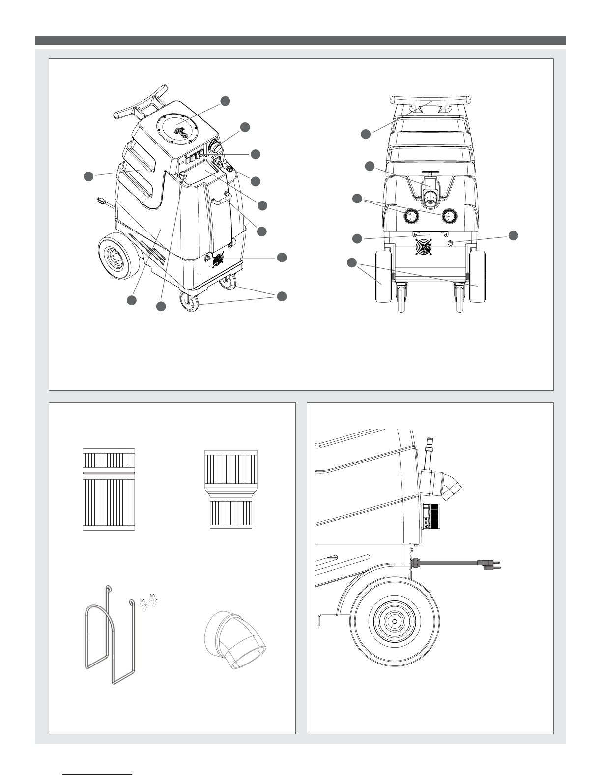
1. Clear recovery tank lid
2. 2” male Cuff-Lynx™
3. Switch plate
4. Female quick disconnect
5. Solution tank lid
1000DX-200 SPEEDSTER
1
2
3
4
6. Front handle
7. Front vent
8. 5” locking casters
9. Faucet ll hose
10. Solution tank
®
FEATURES
12
13
16
14
15
17
5
6
7
8
11. Recovery tank
12. Rear push handle
16. 10” foam-lled wheels
17. Power cord pigtail
13. Recovery tank drain valve
14. Rear exhaust ports
15. Rear bracket
ITEMS INCLUDED
H110 Cuff-Lynx™ H141 Cuff-Lynx™
2” Hose Adapter 2” Hose Reducer to 1.5”
H375-Hose Hanger H226 Drain Elbow
(4) screws
POWER CORD
Plug the power cord into a single, 20A grounded wall outlet.
6
Page 7
1000DX-200 SPEEDSTER
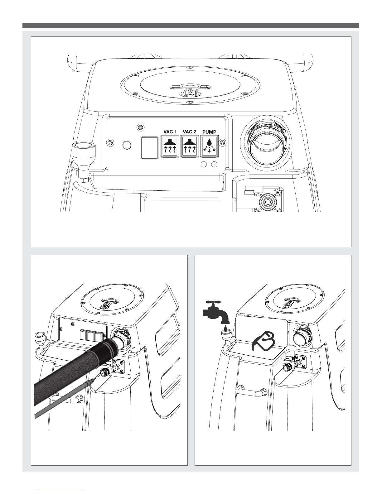
SWITCH PLATE
“On” switches are located on the plate in front of the machine. To use vacuums, turn on Vac 1 and Vac 2 switches. To use
pump, turn on Pump switch.
VACUUM AND SOLUTION HOSE CONNECTIONS
FILLING THE SOLUTION TANK
Attach one end of a solution hose to a wand or other tool,
the other end to the Speedster’s
Attach one end of a vacuum hose to the tool, the other end
to the Speedster’s
®
Cuff-Lynx™ vacuum hose port.
®
front quick disconnect.
Lift lid and manually ll the solution tank or use the easy
faucet ll. IMPORTANT: Before relling the solution
tank, make sure the recovery tank is empty.
7
Page 8
1000DX-200 SPEEDSTER
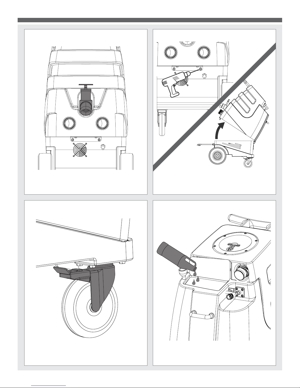
EMPTYING THE RECOVERY TANK
Attach the 45˚ drain elbow to the drain spout in back. Lift up
the dump valve and empty the tank.
OPENING THE SPEEDSTER
To open your Speedster® for maintenance, use a drill with
a 3/8” bit to remove the bolts holding the Speedster’s
®
®
body together. Lift up on the push handle to open the
machine.
LOCKING CASTERS
Locking casters help keep the machine remain stationary
during use.
MYTEE® SYSTEM MAINTAINER
Weekly ushing of the solution system with Mytee® System
Maintainer helps keep lines clean and prevents chemical
build-up, improving pump life, performance and pressure.
8
Page 9
1000DX-200 SPEEDSTER PARTS & PRICING
ITEMS NOT SHOWN
PART NO.
DESCRIPTION
QTY
MSRP
E366
harness, electrical
1 $68.99 ea
G008
piglet filter
1
$6.29 pak
H375
hanger, wire formed, hose
1 $10.99 ea
H230
screw, 10-32 x 1/2" phil pan head, s/s 2 $0.99 ea
H141
Cuff-Lynx, 2" x 1.5" reducer
1 $3.99 ea
H110
Cuff-Lynx, 2" hose x 2" fem swivel Cuff-Lynx
1 $3.99 ea
E530
power cord, ext 50', 12/3 black
1 $74.99 ea
P568A
cord lock, s-type
1 $8.99 ea
ITEM
NO.
PART NO.
DESCRIPTION
QTY.
MSRP
1
H304
screw, #8 x 5/8 phil oval, s/s
14 $0.99 ea
2
H296
guard, cooling fan, wire
2 $2.99 ea
3
H216
nut, lock, 1/4-20, nylon insert, s/s
10 $0.99 ea
4
H210
washer, 1/4" flat, s/s
22 $0.99 ea
5
H342
bolt, 1/4-20 x 1" hex head, s/s 8 $0.99 ea
6
H666
caster, 5", Black hub & gray tread
2 $23.19 ea
7
H371
axle, 18.03" x .50" dia
1 $9.99 ea
8
H254
washer, axle, cut 1/2" id
8 $0.99 ea
9
H109
wheel, 10", foam filled
2 $79.99 ea
10
H042
c-clip, 12mm, external
2 $0.99 ea
11
H876
washer, 1/2 flat, s/s
4 $0.99 ea
12
H221
nut, lock, 1/2" steel
1 $1.99 ea
13
H220
fitting, strain relief, cord
1 $3.19 ea
14
E550
power cord, pigtail, 30", 12/3, black
1 $11.49 ea
15
P731
base
1 $141.99 ea
16
PH615-26
sol hose, 1/2" kuri 100psi
1
$8.99/ft
17
B173
ferrule, 1/2", brass
2 $0.99 ea
18
B160
adapter, brass, 1/2" barb x 3/8" fsw, ball end
1 $3.49 ea
19
B186
elbow, brass, 90 deg, 3/8"mpt x 3/8" fmpt
1 $8.99 ea
20
AH120
sol hose, 28" x 1/4", 1/4 fpt
2 $35.49 ea
21
B652
elbow, brass, 90 deg, 3/8"mpt x 1/4"mpt
1 $8.49 ea
22
H299
washer, 11/16"id x 1-1/2"od x .075, s/s
4 $0.99 ea
23
H222
screw, 10-32 x 1-1/4" phil pan head, s/s
4 $0.99 ea
24
H273
nut, kep, #10-32 zinc
6 $0.99 ea
25
C322D
pump, 220psi, diaphragm,115V
1 $208.99 ea
26
B172
elbow, brass, 90 deg, 1/2" barb x 3/8"mpt
1 $9.49 ea
27
H912
bracket, rear, fb/spy
1 $9.99 ea
28
H770
bolt, 1/4-20 x 1/2" serrated hex flange, zinc
8 $0.99 ea
29
H307
washer, star, 1/4" steel zinc
2 $0.99 ea
30
G052
washer, buna 1-1/8" od x 3/16" id
6 $1.99 ea
31
H211
washer, 1/4"id x 1"od, flat, s/s
6 $0.99 ea
32
H202
bolt, 1/4-20 x 3/4" hex head, s/s
6 $0.99 ea
33
H124
Cuff-Lynx, 2" mpt x 2" female cuff
2 $3.99 ea
34
H194
coupler, 2" dia x 2.5" length, s/s
2 $10.00 ea
35
H217
clamp, hose, 2-1/4 dia
4 $1.49 ea
36
PH628-24
vac hose, 2", wire reinforced
1
$8.99/ft
37
H213
washer, 1/4" lock, s/s
10 $0.99 ea
38
H215
nut, hex, 1/4-20 s/s
2 $0.99 ea
39
PH612-60
clear tubing, 1/2" OD x 3/8" ID, faucet fill
1
$1.99/ft
40
B241
adapter, brass, 3/8" barb x 1/4"mpt
1 $1.99 ea
41
H178
faucet fill
1 $10.99 ea
42
G018
cover, sol tank (sp)
1 $12.99 ea
43
P732
sol tank
1 $141.99 ea
44
H768
bolt, 1/4-20 x 3/4" serrated hex flange, zinc
2 $0.99 ea
45
B107 nipple, brass, 1/4"m, hex
2 $3.19 ea
46
H484
plate, mounting, QD
1 $4.99 ea
47
H256
screw, 10-32 x 3/4" phil pan head, zinc
4 $0.99 ea
48
B142A
coupling, brass, 1/4" fpt x 1/4" fpt
1 $4.49 ea
49
B135
tee, brass, 1/4" mpt
1 $5.49 ea
50
B102
qd, brass, 1/4" f x 1/4" fpt
1 $17.99 ea
51
B656
ball valve, 1/4''
1 $13.49 ea
52
B109
adapter, brass, 1/4" barb x 1/4" mpt
1 $1.99 ea
53
B170
ferrule, 1/4" brass
1 $0.99 ea
54
PH634-36 sol hose, 1/4", silicone braided, clear
1
$6.49 ft
55
H485
handle, aluminim grip, black
1 $6.99 ea
ITEM
NO.
PART NO.
DESCRIPTION
QTY.
MSRP
56
H378
bracket, front hinge, sp/fb
1 $8.99 ea
57
B119A
filter, strainer, 1/2"
1 $6.49 ea
58
B210
bushing, brass, 1/2"mpt x 3/8" fpt, hex
1 $2.49 ea
59
B216
nipple, brass, 3/8" x close
1 $1.99 ea
60
H226
spout, drain, 45 degree
1 $3.19 ea
61
H225
valve, drain, 1-1/2"
1 $20.99 ea
62
P733
vac tank
1 $190.99 ea
63
H314
nut, lock, 1-1/2", steel
2 $1.99 ea
64
PH633-3
pipe, pvc, 1-1/2"
2
$4.99/ft
65
P503
adapter, 1.5" pvc, 45 deg, fslip x fslip
2 $3.29 ea
66
PH633-5
pipe, pvc, 1-1/2"
1
$4.99/ft
67
H343
screw, 10 x 5/8" hex head, zinc
6 $0.99 ea
68
P755
elbow, U, 180, 1-1/2", float
2 $8.99 ea
69
H490
float, 2"/ 1.5" ball style 2 $19.99 ea
70
PH633-12
pipe, pvc, 1-1/2"
1
$4.99/ft
71
P520
adapter, pvc, 1-1/2" mpt x 1-1/2" fms
2 $2.99 ea
72
G090
lid, vac tank, clear, 7"
1 $36.99 ea
73
G091
gasket, 7", vac lid
1 $11.99 ea
74
A926
elbow, inlet assembly 2"
1 $15.99 ea
75
H135
Cuff-Lynx, 2" m cuff x 2" mpt
1 $3.99 ea
76
H422
plug, dome 3/8", black
2 $1.00 ea
77
E515
switch, rocker, 2 position
3 $13.99 ea
78
P967A
plug, switch
1 $1.99 ea
79
H389
screw, 10-32 x 1/2" SHCS, alloy 3 $0.99 ea
80
H612
Washer, #8, flat regular
3 $0.99 ea
81
H434
plug, vent, heyco, 1/2"
1 $4.48 ea
82
H348
plate, switch, 1000DX-200
1 $6.99 ea
83
H390A
bracket, "L"
2 $6.99 ea
84
H096
bolt, hex, 1/4-20 x 4", zinc Finish
6 $0.99 ea
85
H503
vac support, 3 stage, 3.25", no thrds
6 $3.99 ea
86
C302LA
vac motor, 3 stage, low amp
2 $139.99 ea
87
G004
gasket, vacuum motor
2 $8.99 ea
D
C
B
A
B
C
D
1
2
3
4
5
6
7
8
8
7
6
5
4
3
2
1
E
F
E
F
1000DX-200
SHEET 1 OF 3
speedster
10/2013
H
SCALE: 1:48
REV
DWG. NO.
C
SIZE
TITLE:
NAME
DATE
COMMENTS:
CHECKED
DRAWN
PROPRIETARY AND CONFIDENTIAL
THE INFORMATION CONTAINED IN THIS
DRAWING IS THE SOLE PROPERTY OF
MYTEE PRODUCTS, INC. ANY
REPRODUCTION IN PART OR AS A WHOLE
WITHOUT THE WRITTEN PERMISSION OF
MYTEE PRODUCTS, INC. IS
PROHIBITED.
A
DO NOT
SCALE DRAWING
858-679-1191
mytee
PRODUCTS, INC.
M. LaBarbera
9
Part prices are subject to change.
Page 10

1000DX-200 SPEEDSTER PARTS & PRICING
1
2
6
7
8
9
10
12
13
14
15
84
37
4
16
17
18
19
21
22
4
23
25
33
35
27
28
29
28
38
37
31
30
30
31
32
43
44
31
30
20
45
46
47
48
49
50
51
52
54
45
55
4
37
32
3
32
4
59
22
58
57
60
61
62
63
71
72
1
73
74
75
77
78
79
80
79
82
24
83
24
26
56
20
to female qd
thru B107
45
to sol tank
filter thru
B216
59
to pump
"OUT"
thru AH120
20
to pump
"IN"
thru B186
19
34
85
87
42
70
41
64
66
67
28
86
37
3
4
5
81
76
39
53
40
69
65
65
68
11
D
C
B
A
B
C
D
1
2
3
4
5
6
7
8
8
7
6
5
4
3
2
1
E
F
E
F
1000DX-200
SHEET 2 OF 3
speedster
10/2013
H
SCALE: 1:48
REV
DWG. NO.
C
SIZE
TITLE:
NAME
DATE
COMMENTS:
CHECKED
DRAWN
PROPRIETARY AND CONFIDENTIAL
THE INFORMATION CONTAINED IN THIS
DRAWING IS THE SOLE PROPERTY OF
MYTEE PRODUCTS, INC. ANY
REPRODUCTION IN PART OR AS A WHOLE
WITHOUT THE WRITTEN PERMISSION OF
MYTEE PRODUCTS, INC. IS
PROHIBITED.
A
DO NOT
SCALE DRAWING
858-679-1191
mytee
PRODUCTS, INC.
M.LaBarbera
10
Page 11

1000DX-200 SPEEDSTER WIRING SCHEMATIC
8/5/2016
Ground to
Metal Plate
E-515
1000DX-200
115 Volt System
E-515
G
G
G
Pump
C-322D
VAC 2
C-302LA
E-515
L2L1
L2L1
L2L1
G
L1
L2
C-302LA
VAC 1
11
Page 12

1001DX-200 SPEEDSTER
1001DX-200 SPEEDSTER® FEATURES
1
11
10
9
1. Clear recovery tank lid
2. 2” male Cuff-Lynx™
3. Switch plate
4. Female quick disconnect
5. Solution tank lid
2
3
4
6. Front handle
7. Front vent
8. 5” locking casters
9. Faucet ll hose
10. Solution tank
12
13
16
14
15
17
5
6
7
8
11. Recovery tank
12. Rear push handle
16. 10” foam-lled wheels
17. Power cord pigtails
13. Recovery tank drain valve
14. Rear exhaust ports
15. Rear bracket
ITEMS INCLUDED
H110 Cuff-Lynx™ H141 Cuff-Lynx™
2” Hose Adapter 2” Hose Reducer to 1.5”
H375-Hose Hanger H226 Drain Elbow
(4) screws
POWER CORDS
Left cord: Powers Vac 2 & Heater 2.
Right cord: Powers Vac 1, Heater 1 & Pump.
Yellow tag
indicates primary
cord.
Plug each power cord into a separate, 20A grounded wall
outlet. Outlets must be on two separate breakers. When
the amber light on the switch plate illuminates, the machine
is on separate circuits (not necessarily 20A circuits). You
can identify the primary cord by the yellow tag.
12
Page 13

1001DX-200 SPEEDSTER
SWITCH PLATE
In order to use the unit’s heater(s) for hot water extraction, follow thses steps: 1. Turn on the PUMP and pull the trigger on
your cleaning tool until water sprays out. 2. Turn on the HEATER(s). Position 1 on the HEATER switch powers one heating
rod for 1,000 watts and position 2 powers two for 2,000 watts. Allow the heater(s) to warm up for 5-7 minutes. Pull the trigger
on your cleaning tool until hot water sprays out. 3. Turn on the VACUUMS and begin cleaning.
VACUUM AND SOLUTION HOSE CONNECTIONS
FILLING THE SOLUTION TANK
Attach one end of a solution hose to a wand or other tool,
the other end to the Speedster’s
Attach one end of a vacuum hose to the tool, the other end
to the Speedster’s
®
Cuff-Lynx™ vacuum hose port.
®
front quick disconnect.
Lift lid and manually ll the solution tank or use the easy
faucet ll. IMPORTANT: Before relling the solution
tank, make sure the recovery tank is empty.
13
Page 14

1001DX-200 SPEEDSTER
EMPTYING THE RECOVERY TANK
Attach the 45˚ drain elbow to the drain spout in back. Lift
up the dump valve and empty the tank.
OPENING THE SPEEDSTER
To open your Speedster® for maintenance, use a drill with
a 3/8” bit to remove the bolts holding the Speedster’s
®
®
body together. Lift up on the push handle to open the
machine.
LOCKING CASTERS
Locking casters help keep the machine remain stationary
during use.
MYTEE® SYSTEM MAINTAINER
Weekly ushing of the solution system with Mytee
®
System
Maintainer helps keep lines clean and prevents chemical
build-up, improving pump life, performance and pressure.
14
Page 15

1001DX-200 SPEEDSTER PARTS & PRICING
ITEMS NOT SHOWN
PART NO.
DESCRIPTION
QTY
MSRP
A996
harness, electrical
1
$88.99 ea
G008
piglet filter
1
$6.29 pak
H375
hanger, wire formed, hose
1
$10.99 ea
H230
screw, 10-32 x 1/2" phil pan head, s/s
2
$0.99 ea
H141
Cuff-Lynx, 2" x 1.5" reducer
1
$3.99 ea
H110
Cuff-Lynx, 2" hose x 2" fem swivel Cuff-Lynx
1
$3.99 ea
E530
power cord, ext 50', 12/3 black
2
$74.99 ea
P568A
cord lock, s-type
2
$8.99 ea
P590
cuties, 1/4" qd, standard pack of 2
1
$2.99 ea
ITEM
NO.
PART NO.
DESCRIPTION
QTY.
MSRP
1
H304
screw, #8 x 5/8 phil oval, s/s
14
$0.99 ea
2
H296
guard, cooling fan, wire
2
$2.99 ea
3
H216
nut, lock, 1/4-20, nylon insert, s/s
10
$0.99 ea
4
H210
washer, 1/4" flat, s/s
22
$0.99 ea
5
H342
bolt, 1/4-20 x 1" hex head, s/s 8
$0.99 ea
6
H666
caster, 5", Black hub & gray tread
2
$23.19 ea
7
P731
base
1
$141.99 ea
8
H371
axle, 18.03" x .50" dia
1
$9.99 ea
9
H254
washer, axle, cut 1/2" id
8
$0.99 ea
10
H109
wheel, 10", foam filled
2
$79.99 ea
11
H042
c-clip, 12mm, external
2
$0.99 ea
12
AH184
sol hose, pulse, 3/8" x 14.5" fsw x 1/4 fsw x 1/4 fpt
1
$27.99 ea
13
AH156
hose, 3/8", (OAL), f x fs, 5400 gray
1
$23.99 ea
14
B103
elbow, brass, 90 deg, 1/4"mpt x 1/4" fpt
2
$4.49 ea
15
H256
screw, 10-32 x 3/4" phil pan head, zinc
6
$0.99 ea
16
H528
bracket, heater mounting, dual
1
$29.99 ea
17
E519
heating rod, 1000W, 115V
2
$51.99 ea
18
B142A
coupling, brass, 1/4" fpt x 1/4" fpt
2
$4.49 ea
19
B108
valve, brass, 1/4" check
1
$13.99 ea
20
H274
screw, 6 x 3/16, phil pan head, self-tapping
10
$0.99 ea
21
H903A
heater, aluminum cast, single
2
$78.99 ea
22
E573
Thermostat, 200°, Auto, 1/4"
2
$16.49 ea
23
E574
Thermostat, 310°F ± 10°F, Manual, 1/4"
2
$17.99 ea
24
AH120
sol hose, 28" x 1/4", 1/4 fpt
2
$35.49 ea
25
H876
washer, 1/2 flat, s/s 4
$0.99 ea
26
H221
nut, lock, 1/2" steel
2
$1.99 ea
27
H220
fitting, strain relief, cord
2
$3.19 ea
28
E550
power cord, pigtail, 30", 12/3, black
2
$11.49 ea
29
PH615-26
sol hose, 1/2" kuri 100psi
1
$8.99/ft
30
B160
adapter, brass, 1/2" barb x 3/8" fsw, ball end
1
$3.49 ea
31
B186
elbow, brass, 90 deg, 3/8"mpt x 3/8" fmpt
1
$8.99 ea
32
B652
elbow, brass, 90 deg, 3/8"mpt x 1/4"mpt
1
$8.49 ea
33
H299
washer, 11/16"id x 1-1/2"od x .075, s/s
4
$0.99 ea
34
H222
screw, 10-32 x 1-1/4" phil pan head, s/s 4
$0.99 ea
35
C322D
pump, 220psi, diaphragm,115V
1
$208.99 ea
36
B172
elbow, brass, 90 deg, 1/2" barb x 3/8"mpt
1
$9.49 ea
37
B173
ferrule, 1/2", brass
2
$0.99 ea
38
H273
nut, kep, #10-32 zinc
8
$0.99 ea
39
H912
bracket, rear, fb/spy
1
$9.99 ea
40
H770
bolt, 1/4-20 x 1/2" serrated hex flange, zinc
8
$0.99 ea
41
H307
washer, star, 1/4" steel zinc
2
$0.99 ea
42
G052
washer, buna 1-1/8" od x 3/16" id
6
$1.99 ea
43
H211
washer, 1/4"id x 1"od, flat, s/s
6
$0.99 ea
44
H203
bolt, 1/4-20 x 1-1/4"
2
$0.99 ea
45
H124
Cuff-Lynx, 2" mpt x 2" female cuff
2
$3.99 ea
46
H194
coupler, 2" dia x 2.5" length, s/s
2
$10.00 ea
47
H217
clamp, hose, 2-1/4 dia
4
$1.49 ea
48
PH628-15
vac hose, 2", wire reinforced
2
$8.99/ft
49
H213
washer, 1/4" lock, s/s
10
$0.99 ea
50
H215
nut, hex, 1/4-20 s/s
2
$0.99 ea
51
PH612-60
clear tubing, 1/2" OD x 3/8" ID, faucet fill
1
$1.99/ft
52
G018
cover, sol tank (sp)
1
$12.99 ea
53
H178
faucet fill
1
$10.99 ea
54
B241
adapter, brass, 3/8" barb x 1/4"mpt
1
$1.99 ea
55
P732
sol tank
1
$141.99 ea
56
H768
bolt, 1/4-20 x 3/4" serrated hex flange, zinc
2
$0.99 ea
57
B107
nipple, brass, 1/4"m, hex
2
$3.19 ea
58
H484
plate, mounting, QD
1
$4.99 ea
59
B135
tee, brass, 1/4" mpt
1
$5.49 ea
60
B102
qd, brass, 1/4" f x 1/4" fpt
1
$17.99 ea
61
B656
ball valve, 1/4'' 1
$13.49 ea
62
B109
adapter, brass, 1/4" barb x 1/4" mpt
1
$1.99 ea
ITEM
NO.
PART NO.
DESCRIPTION
QTY.
MSRP
63
B170
ferrule, 1/4" brass
2
$0.99 ea
64
PH634-20 sol hose, 1/4", silicone braided, clear
1
$6.49 ft
65
H485
handle, aluminim grip, black
1
$6.99 ea
66
H201
bolt, 1/4-20 x 1/2", hex head, zinc
2
$0.99 ea
67
H378
bracket, front hinge, sp/fb
1
$8.99 ea
68
H316
bolt, 1/4x1-1/2", hex head zinc
2
$0.99 ea
69
B119A
filter, strainer, 1/2"
1
$6.49 ea
70
B210
bushing, brass, 1/2"mpt x 3/8" fpt, hex
1
$2.49 ea
71
B216
nipple, brass, 3/8" x close
1
$1.99 ea
72
H226
spout, drain, 45 degree
1
$3.19 ea
73
H225
valve, drain, 1-1/2"
1
$20.99 ea
74
P733
vac tank
1
$190.99 ea
75
A926
elbow, inlet assembly 2"
1
$15.99 ea
76
PH633-3
pipe, pvc, 1-1/2"
2
$4.99/ft
77
P503
adapter, 1.5" pvc, 45 deg, fslip x fslip
2
$3.29 ea
78
PH633-5
pipe, pvc, 1-1/2"
1
$4.99/ft
79
H343
screw, 10 x 5/8" hex head, zinc
6
$0.99 ea
80
H490
float, 2"/ 1.5" ball style
2
$19.99 ea
81
P755
elbow, U, 180, 1-1/2", float
2
$8.99 ea
82
G091
gasket, 7", vac lid
1
$11.99 ea
83
G090 lid, vac tank, clear, 7"
1
$36.99 ea
84
PH633-12
pipe, pvc, 1-1/2"
1
$4.99/ft
85
P520
adapter, pvc, 1-1/2" mpt x 1-1/2" fms
2
$2.99 ea
86
H314
nut, lock, 1-1/2", steel
2
$1.99 ea
87
H135
Cuff-Lynx, 2" m cuff x 2" mpt
1
$3.99 ea
88
E511
light, red, 250v
2
$5.99 ea
89
E516
switch, rocker, 3 position
1
$14.99 ea
90
E515
switch, rocker, 2 position
3
$13.99 ea
91
E512B
light, indicator, 125v (amber)
1
$9.99 ea
92
H389
screw, 10-32 x 1/2" SHCS, alloy 4
$0.99 ea
93
H612
Washer, #8, flat regular
3
$0.99 ea
94
H348
plate, switch, 1000DX-200
1
$6.99 ea
95
H390A
bracket, "L"
2
$6.99 ea
96
H096
bolt, hex, 1/4-20 x 4", zinc Finish
6
$0.99 ea
97
H503
vac support, 3 stage, 3.25", no thrds
6
$3.99 ea
98
C302LA
vac motor, 3 stage, low amp
2
$139.99 ea
99
G004
gasket, vacuum motor
2
$8.99 ea
100
E564
controller, circuit light
1
$62.99 ea
D
C
B
A
B
C
D
1
2
3
4
5
6
7
8
8
7
6
5
4
3
2
1
E
F
E
F
1001DX-200
SHEET 1 OF 3
speedster
10/2013
G
SCALE: 1:48
REV
DWG. NO.
C
SIZE
TITLE:
NAME
DATE
CHECKED
DRAWN
PROPRIETARY AND CONFIDENTIAL
THE INFORMATION CONTAINED IN THIS
DRAWING IS THE SOLE PROPERTY OF
MYTEE PRODUCTS, INC. ANY
REPRODUCTION IN PART OR AS A WHOLE
WITHOUT THE WRITTEN PERMISSION OF
MYTEE PRODUCTS, INC. IS
PROHIBITED.
A
DO NOT
SCALE DRAWING
858-679-1191
mytee
PRODUCTS, INC.
M. LaBarbera
15
Part prices are subject to change.
Page 16

1001DX-200 SPEEDSTER PARTS & PRICING
1
2
6
7
8
9
10
11
12
14
38
16
17
20
18
19
21
20
22
23
24
13
15
28
27
26
29
37
30
31
32
33
34
4
35
36
38
45
48
47
69
70
33
71
39
40
41
40
42
43
44
42
43
49
50
55
24
57
58
15
18
59
60
61
62
63
57
56
43
42
65
4
49
66
3
4
68
67
72
73
74
94
89
91
92
93
95
100
92
38
87
75
82
83
1
85
86
88
90
to heater
"OUT"
thru AH105
24
to female
QD thru
B107
57
to pump
"OUT"
thru B136
32
to sol tank
filter thru
B216
71
to pump
"IN"
thru B186
31
46
96
49
4
97
98
99
76
52
84
53
78
79
40
3
4
5
64
51 54
to heater
"IN"
thru AH156
12
80
77
81
76
77
25
D
C
B
A
B
C
D
1
2
3
4
5
6
7
8
8
7
6
5
4
3
2
1
E
F
E
F
1001DX-200
SHEET 2 OF 3
speedster
10/2013
G
SCALE: 1:48
REV
DWG. NO.
C
SIZE
TITLE:
NAME
DATE
CHECKED
DRAWN
PROPRIETARY AND CONFIDENTIAL
THE INFORMATION CONTAINED IN THIS
DRAWING IS THE SOLE PROPERTY OF
MYTEE PRODUCTS, INC. ANY
REPRODUCTION IN PART OR AS A WHOLE
WITHOUT THE WRITTEN PERMISSION OF
MYTEE PRODUCTS, INC. IS
PROHIBITED.
A
DO NOT
SCALE DRAWING
858-679-1191
mytee
PRODUCTS, INC.
M.LaBarbera
16
Page 17

1001DX-200 SPEEDSTER WIRING SCHEMATIC
L1
L2
G
L1
L2
G
VAC 1
L2L1
G
VAC 2
L2L1
G
E-516
Pump
L2L1
G
1000 Watt Heat
1000 Watt Heat
1000 Watt 1000 Watt
G
G
C-302LA
C-302LA
C-322D
E-519
E-519
Secondary Cord
Primary Cord
E-515
E-515
E-515
E-564
L2a
L1b
L1a
L2b
light
7/29/2016
1001DX-200
115 Volt System
Ground to
switch plate
17
Page 18

1003DX SPEEDSTER
1003DX SPEEDSTER® FEATURES
1
13
12 11
1. Clear recovery tank lid
2. 2” male Cuff-Lynx™
3. Switch plate
4. Pressure gauge
5. Female quick disconnect
ITEMS INCLUDED
2
3
6. Solution tank lid
7. Front handle
8. Pressure regulator
9. Front vent
10. 5” locking casters
14
4
15
5
18
16
17
19
6
7
8
9
10
11. Faucet ll hose
12. Solution tank
13. Recovery tank
14. Rear push handle
16. Rear exhaust ports
17. Rear bracket
18. 10” foam-lled wheels
19. Power cord pigtails
15. Recovery tank drain valve
POWER CORD
H110 Cuff-Lynx™ H141 Cuff-Lynx™
2” Hose Adapter 2” Hose Reducer to 1.5”
H375-Hose Hanger H226 Drain Elbow
(4) screws
Left cord: Powers Vac 2 & Heater 2.
Right cord: Powers Vac 1, Heater 1 & Pump.
Yellow tag
indicates primary
cord.
Plug each power cord into a separate, 20A grounded wall
outlet. Outlets must be on two separate breakers. When
the amber light on the switch plate illuminates, the machine
is on separate circuits (not necessarily 20A circuits). You
can identify the primary cord by the yellow tag.
18
Page 19

1003DX SPEEDSTER
SWITCH PLATE
In order to use the unit’s heater(s) for hot water extraction, follow thses steps: 1. Turn on the PUMP and pull the trigger on
your cleaning tool until water sprays out. 2. Turn on the HEATER(s). Position 1 on the HEATER switch powers one heating
rod for 1,000 watts and position 2 powers two for 2,000 watts. Allow the heater(s) to warm up for 5-7 minutes. Pull the trigger
on your cleaning tool until hot water sprays out. 3. Turn on the VACUUMS and begin cleaning.
FILLING THE SOLUTION TANKVACUUM AND SOLUTION HOSE CONNECTIONS
Attach one end of a solution hose to a wand or other tool,
the other end to the Speedster’s
Attach one end of a vacuum hose to the tool, the other end
to the Speedster’s
®
Cuff-Lynx™ vacuum hose port.
®
front quick disconnect.
Lift lid and manually ll the solution tank or use the easy
faucet ll. IMPORTANT: Before relling the solution
tank, make sure the recovery tank is empty.
19
Page 20

1003DX SPEEDSTER
PRIME VALVE & PRESSURE REGULATOR
PRIME POSITION
HIGHER PSI
PRESSURE
RUN POSITION
Ball valve is
*
located near
the QD.
LOWER PSI
REGULATOR
Prime the pump by turning the valve to the Prime position
(as shown above) for 30 seconds, then turn right to the
Run position. Turn the Pressure Regulator to the left to
decrease water pressure. Turn the Pressure Regulator to
the right to increase water pressure.
OPENING THE SPEEDSTER
To open your Speedster® for maintenance, use a drill with
a 3/8” bit to remove the bolts holding the Speedster’s
®
®
body together. Lift up on the push handle to open the
machine.
DUMP VALVE & LOCKING CASTERS
Above, empty the recovery tank by attaching the 45˚ drain
elbow to the drain spout in back. Lift up the dump valve
and empty the tank. Below, locking casters help keep the
machine remain stationary during use.
MYTEE® SYSTEM MAINTAINER
®
Weekly ushing of the solution system with Mytee
System
Maintainer helps keep lines clean and prevents chemical
build-up, improving pump life, performance and pressure.
20
Page 21

1003DX SPEEDSTER PARTS & PRICING
ITEMS NOT SHOWN
ITEM
NO.
PART NO.
DESCRIPTION
QTY.
MSRP
1
H296
guard, cooling fan, wire
2 $2.99 ea
2
H304
screw, #8 x 5/8 phil oval, s/s
14 $0.99 ea
3
H216
nut, lock, 1/4-20, nylon insert, s/s
14 $0.99 ea
4
H210
washer, 1/4" flat, s/s
26 $0.99 ea
5
H342
bolt, 1/4-20 x 1" hex head, s/s 12 $0.99 ea
6
H666
caster, 5", Black hub & gray tread
2 $23.19 ea
7
H273
nut, kep, #10-32 zinc
6 $0.99 ea
8
E564
controller, circuit light
1 $62.99 ea
9
H186
screw, 10-32 x 3/4, phil flat full thread
2 $0.99 ea
10
H371
axle, 18.03" x .50" dia
1 $9.99 ea
11
H254
washer, axle, cut 1/2" id
10 $0.99 ea
12
H109
wheel, 10", foam filled
2 $79.99 ea
13
H042
c-clip, 12mm, external
2 $0.99 ea
14
H876
washer, 1/2 flat, s/s 4 $0.99 ea
15
H221
nut, lock, 1/2" steel
2 $1.99 ea
16
H220
fitting, strain relief, cord
2 $3.19 ea
17
E550
power cord, pigtail, 30", 12/3, black
2 $11.49 ea
18
P731
base
1 $141.99 ea
19
H256
screw, 10-32 x 3/4" phil pan head, zinc
6 $0.99 ea
20
H528
bracket, heater mounting, dual
1 $29.99 ea
21
H903A
heater, aluminum cast, single
2 $78.99 ea
22
E571
heating rod, 600W, 115V
1 $49.99 ea
23
E574
Thermostat, 310°F ± 10°F, Manual, 1/4"
2 $17.99 ea
24
H274
screw, 6 x 3/16, phil pan head, self-tapping
10 $0.99 ea
25
E573
Thermostat, 200°, Auto, 1/4"
2 $16.49 ea
26
E519
heating rod, 1000W, 115V
1 $51.99 ea
27
B207
elbow, brass, 90 deg, 1/4" fpt x 1/4" fpt 1 $5.99 ea
28
B107 nipple, brass, 1/4"m, hex
5 $3.19 ea
29
AH156
hose, 3/8" x 6.5", (OAL), f x fsw, 5400 Gray
1 $23.99 ea
30
B103
elbow, brass, 90 deg, 1/4"mpt x 1/4" fpt 5 $4.49 ea
31
B113
tee, brass, 1/4" fpt
1 $6.99 ea
32
B643 adapter, brass, 3/8" fnpt x 1/4" mnpt
1 $4.99 ea
33
AH120
sol hose, 28" x 1/4", 1/4 fpt
1 $35.99 ea
34
B259
qd, brass, 1/4" fqd x mpt
1 $11.99 ea
35
B260
qd, brass, 1/4" mqd x fpt
1 $10.49 ea
36
AH184
hose, pulse, 3/8" x 17-1/2", (OAL)
2 $31.99 ea
37
B652
elbow, brass, 90 deg, 3/8"mpt x 1/4"mpt
3 $8.49 ea
38
B259A
qd, brass, 1/4" fqd x fpt
3 $15.99 ea
39
B260A
qd, brass, 1/4" mqd x fpt
3 $8.99 ea
40
C313A
pump, CAT, 50-500 PSI, 120/240v
1 $599.99 ea
41
B186
elbow, brass, 90 deg, 3/8"mpt x 3/8" fmpt
2 $8.99 ea
42
B105
bushing, brass, 3/8"mpt x 1/4" 1 $3.19 ea
43
PH615-36
sol hose, 1/2" kuri 100psi
1
$8.99/ft
44
B644
adapter, brass, 1/2" barb x 1/4" mpt
1 $2.49 ea
45
B173
ferrule, 1/2", brass
2 $0.99 ea
46
B160
adapter, brass, 1/2" barb x 3/8" fsw, ball end
1 $3.49 ea
47
B110
adapter, brass, 1/4" sw barb x 1/4" fpt, w/gasket
1 $3.99 ea
48
PH634-20
sol hose, 1/4", 300psi, black
1
$6.49/ft
49
B170
ferrule, 1/4" brass
3 $0.99 ea
50
B119
filter, strainer, 1/4"
1 $3.99 ea
51
B152
elbow, brass, 90 deg, 1/4" barb x 1/4" mpt
1 $5.49 ea
52
H044
bracket, regulator, panel mount
1 $27.99 ea
53
B127
plug, brass, 1/4"mpt, hex
1 $0.99 ea
54
C313C
regulator, 450 psi, silver spring
1 $86.99 ea
55
H770
bolt, 1/4-20 x 1/2" serrated hex flange, zinc
8 $0.99 ea
56
H912
bracket, rear, fb/spy
1 $9.99 ea
57
H124
Cuff-Lynx, 2" mpt x 2" female cuff
2 $3.99 ea
58
H194
coupler, 2" dia x 2.5" length, s/s
2 $10.00 ea
59
H217
clamp, hose, 2-1/4 dia
4 $1.49 ea
60
PH628-20
vac hose, 2", wire reinforced
2
$8.99/ft
61
P732
sol tank
1 $141.99 ea
62
H390A
bracket, "L"
2 $6.99 ea
63
PH612-60
clear tubing, 1/2" OD x 3/8" ID, faucet fill
1
$1.99/ft
64
B241
adapter, brass, 3/8" barb x 1/4"mpt
1 $1.99 ea
65
H178
faucet fill
1 $10.99 ea
66
G018
cover, sol tank (sp)
1 $12.99 ea
67
H203
bolt, 1/4-20 x 1-1/4"
2 $0.99 ea
68
H211
washer, 1/4"id x 1"od, flat, s/s
6 $0.99 ea
69
G052
washer, buna 1-1/8" od x 3/16" id
6 $1.99 ea
ITEM
NO.
PART NO.
DESCRIPTION
QTY.
MSRP
70
H213
washer, 1/4" lock, s/s
10 $0.99 ea
71
H215
nut, hex, 1/4-20 s/s
2 $0.99 ea
72
H768
bolt, 1/4-20 x 3/4" serrated hex flange, zinc
2 $0.99 ea
73
AH108S
sol hose, 1/4" x 24 1/2", (OAL)
1 $26.49 ea
74
H484
plate, mounting, QD
1 $4.99 ea
75
B142A
coupling, brass, 1/4" fpt x 1/4" fpt
1 $4.49 ea
76
B135
tee, brass, 1/4" mpt
1 $5.49 ea
77
B102
qd, brass, 1/4" f x 1/4" fpt
1 $17.99 ea
78
B656
ball valve, 1/4'' 1 $13.49 ea
79
B109
adapter, brass, 1/4" barb x 1/4" mpt
1 $1.99 ea
80
PH634-36 sol hose, 1/4", 300 PSI
1
$6.49 ft
81
H485
handle, aluminim grip, black
1 $6.99 ea
82
H316
bolt, 1/4x1-1/2", hex head zinc
2 $0.99 ea
83
H378
bracket, front hinge, sp/fb
1 $8.99 ea
84
H201
bolt, 1/4-20 x 1/2", hex head, zinc
2 $0.99 ea
85
H299
washer, 11/16"id x 1-1/2"od x .075, s/s
4 $0.99 ea
86
B216
nipple, brass, 3/8" x close
1 $1.99 ea
87
B210
bushing, brass, 1/2"mpt x 3/8" fpt, hex
1 $2.49 ea
88
B119A
filter, strainer, 1/2"
1 $6.49 ea
89
H314
nut, lock, 1-1/2", steel
2 $1.99 ea
90
P520
adapter, pvc, 1-1/2" mpt x 1-1/2" fms
2 $2.99 ea
91
PH633-3
pipe, pvc, 1-1/2"
2
$4.99/ft
92
PH633-5
pipe, pvc, 1-1/2"
1
$4.99/ft
93
P503
adapter, 1.5" pvc, 45 deg, fslip x fslip
2 $3.29 ea
94
H343
screw, 10 x 5/8" hex head, zinc
6 $0.99 ea
95
P755
elbow, U, 180, 1-1/2", float
2 $8.99 ea
96
H490
float, 2"/ 1.5" ball style 2 $19.99 ea
97
PH633-12
pipe, pvc, 1-1/2"
1
$4.99/ft
98
H226
spout, drain, 45 degree
1 $3.19 ea
99
H225
valve, drain, 1-1/2"
1 $20.99 ea
100
P733
vac tank
1 $190.99 ea
101
A926
elbow, inlet assembly 2"
1 $15.99 ea
102
G091
gasket, 7", vac lid
1 $11.99 ea
103
G090 lid, vac tank, clear, 7"
1 $36.99 ea
104
H135
Cuff-Lynx, 2" m cuff x 2" mpt
1 $3.99 ea
105
E512B
light, indicator, 125v (amber)
1 $9.99 ea
106
H337
plate, switch,1003DX, 1005DX
1 $8.99 ea
107
E511
light, red, 250v
2 $5.99 ea
108
E515
switch, rocker, 2 position
3 $13.99 ea
109
E516
switch, rocker, 3 position
1 $14.99 ea
110
H389
screw, 10-32 x 1/2" SHCS, alloy 1 $0.99 ea
111
H612
Washer, #8, flat regular
3 $0.99 ea
112
H246
screw, 8-32 x 3/8" SHCS, alloy, Black
2 $0.99 ea
113
H308D
gauge, pressure, 2000psi
1 $38.99 ea
114
AH203
hose, pulse, 38" x 34"
1 $47.99 ea
115
H503
vac support, 3 stage, 3.25", no thrds
6 $3.99 ea
116
H096
bolt, hex, 1/4-20 x 4", zinc Finish
6 $0.99 ea
117
C302LA
vac motor, 3 stage, low amp
2 $139.99 ea
118
G004
gasket, vacuum motor
2 $8.99 ea
PART NO.
DESCRIPTION
QTY.
MSRP
E380
harness, electrical
1 $129.99 ea
G008
piglet filet
1
$6.29 pak
H375
hanger, wire forned, hose
1 $10.99 ea
H230
screw, 10-32 x 1/2" phil pan head, s/s 2 $0.99 ea
H141
Cuff-Lynx, 2" to 1.5" reducer
1 $3.99 ea
E530
power cord, ext 50', 12/3 black
2 $74.99 ea
H110
Cuff-Lynx, 2" hose x 2" fem swivel Cuff-Lynx
1 $3.99 ea
P568A
cord lock, s-type
2 $8.99 ea
P590
cuties, 1/4" qd, standard pack of 2
1 $2.99 ea
ADM-SPEEDSTERS
manual, speedsters
1
D
C
B
A
A
B
C
D
1
2
3
4
5
6
7
8
8
7
6
5
4
3
2
1
E
F
E
F
REV
1003DX (2016)
D
1003DX
SHEET 1 OF 3
speedster
SCALE: 1:48
REV
DWG. NO.
D
SIZE
TITLE:
NAME
DATE
COMMENTS:
CHECKED
DRAWN
PROPRIETARY AND CONFIDENTIAL
THE INFORMATION CONTAINED IN THIS
DRAWING IS THE SOLE PROPERTY OF
MYTEE PRODUCTS, INC. ANY
REPRODUCTION IN PART OR AS A WHOLE
WITHOUT THE WRITTEN PERMISSION OF
MYTEE PRODUCTS, INC. IS PROHIBITED.
mytee
PRODUCTS, INC.
858-679-1191
M. LaBarbera
10/2013
G
DO NOT SCALE
DRAWING
21
Part prices are subject to change.
Page 22

1003DX SPEEDSTER PARTS & PRICING
1
2
6
11
10
12
13
15
16
17
18
7
19
20
21
23
24
25
26
27
28
29
30
30
35
34
33
28
31
32
3
4
5
36
37
38
39
40
41
42
39
43
44
38
46
48
30
11
28
50
11
37
38
39
38
51
53
54
37
57
58
59
60
62
67
68
69
69
68
70
71
72 68
69
73
28
74
19
75
76
77
78
79
80
28
81
82
4
3
83
84
70
88
87
85
8685
41
89
90
92
98
99
100
101
102
2
104
106
107
108
109
110
111
112
114
105
7
30
113
118
117
4
70
116
115
55
4
56
55
61
103
to pump
"OUT"
thru AH184
36
to heater
"IN"
thru B107
28
to pressure
gauge
thru AH203
114
to female
QD
thru B107
28
to sol
tank filter
thru B186
41
to pump
"IN"
thru B160
46
to heater
"OUT"
thru B113
31
22
to heater
"OUT"
thru B643
32
66
97
65
91
55
52
7
8
9
3
4
5
49
45
49
63
64
47
93
91
96
95
94
14
D
C
B
A
B
C
D
1
2
3
4
5
6
7
8
8
7
6
5
4
3
2
1
E
F
E
F
1003DX
SHEET 2 OF 3
speedster
10/2013
G
SCALE: 1:48
REV
DWG. NO.
C
SIZE
TITLE:
NAME
DATE
COMMENTS:
CHECKED
DRAWN
PROPRIETARY AND CONFIDENTIAL
THE INFORMATION CONTAINED IN THIS
DRAWING IS THE SOLE PROPERTY OF
MYTEE PRODUCTS, INC. ANY
REPRODUCTION IN PART OR AS A WHOLE
WITHOUT THE WRITTEN PERMISSION OF
MYTEE PRODUCTS, INC. IS
PROHIBITED.
A
DO NOT
SCALE DRAWING
858-679-1191
mytee
PRODUCTS, INC.
M.LaBarbera
22
Page 23

1003DX SPEEDSTER WIRING SCHEMATIC
10/5/2015
1003DX
115 Volt System
E-515
G
G
Pump
C313A
VAC 2
C-302LA
E-515
E-515
G
L2L1
E519
1000 Watt Heat
L2L1
E-516
600 Watt 1000 Watt
G
E571
600 Watt Heat
G
L1
Primary Cord
L2
G
VAC 1
C-302LA
L2a
L1a
L2L1
light
L1b
L2b
E-564
Ground to
switch plate
G
L1
L2
Secondary Cord
23
Page 24

1005DX SPEEDSTER
1
2
1005DX SPEEDSTER
13
®
FEATURES
14
3
4
5
6
7
8
1. Clear recovery tank lid
2. Pressure gauge
3. Faucet ll hose
4. Switch plate
5. Solution tank lid
ITEMS INCLUDED
12
11
10
9
6. Front handle
7. Front vent
8. 5” locking casters
9. Solution tank
10. Female quick disconnect
15
16
17
11. Pressure regulator
12. 2” male Cuff-Lynx™
13. Recovery tank
14. Rear push handle
15. Recovery tank drain valve
POWER CORD
Left cord: Powers power Vac 2.
Right cord: Powers Vac 1 & Pump.
19
18
16. Rear exhaust ports
17. Rear bracket
18. 10” foam-lled wheels
19. Power cord pigtails
H110 Cuff-Lynx™ H141 Cuff-Lynx™
2” Hose Adapter 2” Hose Reducer to 1.5”
H375-Hose Hanger H226 Drain Elbow
(4) screws
Yellow tag
indicates primary
cord.
Plug each power cord into a separate, 20A grounded wall
outlet. Outlets must be on two separate breakers. When
the amber light on the switch plate illuminates, the machine
is on separate circuits (not necessarily 20A circuits). You
can identify the primary cord by the yellow tag.
24
Page 25

1005DX SPEEDSTER
SWITCH PLATE
“On” switches are located on the plate in front of the machine. To use vacuums, turn on Vac 1 and Vac 2 switches. To use
pump, turn on Pump switch.
FILLING THE SOLUTION TANKVACUUM AND SOLUTION HOSE CONNECTIONS
Attach one end of a solution hose to a wand or other tool,
the other end to the Speedster’s
Attach one end of a vacuum hose to the tool, the other end
to the Speedster’s
®
Cuff-Lynx™ vacuum hose port.
®
front quick disconnect.
Lift lid and manually ll the solution tank or use the easy
faucet ll. IMPORTANT: Before relling the solution
tank, make sure the recovery tank is empty.
25
Page 26

1005DX SPEEDSTER
PRIME VALVE & PRESSURE REGULATOR
HIGHER PSI
PRIME POSITION
PRESSURE
REGULATOR
RUN POSITION
LOWER PSI
Prime the pump by turning the valve to the Prime position
(as shown above) for 30 seconds, then turn right to the
Run position. Turn the Pressure Regulator to the left to
decrease water pressure. Turn the Pressure Regulator to
the right to increase water pressure.
OPENING THE SPEEDSTER
To open your Speedster® for maintenance, use a drill with
a 3/8” bit to remove the bolts holding the Speedster’s
®
®
body together. Lift up on the push handle to open the
machine.
DUMP VALVE & LOCKING CASTERS
Above, empty the recovery tank by attaching the 45˚ drain
elbow to the drain spout in back. Lift up the dump valve
and empty the tank. Below, locking casters help keep the
machine remain stationary during use.
MYTEE® SYSTEM MAINTAINER
Weekly ushing of the solution system with Mytee
®
System
Maintainer helps keep lines clean and prevents chemical
build-up, improving pump life, performance and pressure.
26
Page 27

1005DX SPEEDSTER PARTS & PRICING
ITEMS NOT SHOWN
ITEM
NO.
PART NO.
DESCRIPTION
QTY.
MSRP
1
H296
guard, cooling fan, wire
2
$2.99 ea
2
H304
screw, 8 x 5/8", phil oval, s/s
14
$0.99 ea
3
H378
bracket, front hinge, sp/fb
1
$8.99 ea
4
H210
washer, 1/4" flat, s/s
26
$0.99 ea
5
H213
washer, 1/4" lock, s/s
10
$0.99 ea
6
H201
bolt, 1/4-20 x 1/2", hex head, zinc
2
$0.99 ea
7
H216
nut, lock, 1/4-20, nylon insert, s/s
14
$0.99 ea
8
H316
bolt, 1/4x1-1/2", hex head zinc
2
$0.99 ea
9
H342
bolt, 1/4-20 x 1" hex head, s/s 8
$0.99 ea
10
H666
caster, 5", Black hub & gray tread
2
$23.19 ea
11
P731
base
1
$141.99 ea
12
H371
axle, 18.03" x .50" dia
1
$9.99 ea
13
H254
washer, axle, cut 1/2" id
8
$0.99 ea
14
H109
wheel, 10", foam filled
2
$79.99 ea
15
H042
c-clip, 12mm, external
2
$0.99 ea
16
H876
washer, 1/2 flat, s/s 4
$0.99 ea
17
E550
power cord, pigtail, 30", 12/3, black
2
$11.49 ea
18
H220
fitting, strain relief, cord
2
$3.19 ea
19
H221
nut, lock, 1/2" steel
2
$1.99 ea
20
H912
bracket, rear, fb/spy
1
$9.99 ea
21
H307
washer, star, 1/4" steel zinc
2
$0.99 ea
22
H770
bolt, 1/4-20 x 1/2" serrated hex flange, zinc
8
$0.99 ea
23
H202
bolt, 1/4x20x3/4" hex head
4
$0.99 ea
24
B246
plug, brass, 3/8" mpt, hex
1
$1.99 ea
25
B186
elbow, brass, 90 deg, 3/8"mpt x 3/8" fmpt
2
$8.99 ea
26
B105
bushing, brass, 3/8"mpt x 1/4"
1
$3.19 ea
27
B260A
qd, brass, 1/4" mqd x fpt
2
$8.99 ea
28
B259A
qd, brass, 1/4" fqd x fpt
2
$15.99 ea
29
B644
adapter, brass, 1/2" barb x 1/4" mpt
1
$2.49 ea
30
PH615-37
sol hose, 1/2" kuri, 100 psi
1
$8.99 ft
31
B173
ferrule, 1/2", brass
2
$0.99 ea
32
B160
adapter, brass, 1/2" barb x 3/8" fsw, ball end
1
$3.49 ea
33
B652
elbow, brass, 90 deg, 3/8"mpt x 1/4"mpt
1
$8.49 ea
34
B107
nipple, brass, 1/4"m, hex
3
$3.19 ea
35
B643 adapter, brass, 3/8" fnpt x 1/4" mnpt
1
$4.99 ea
36
B113
tee, brass, 1/4" fpt
1
$6.99 ea
37
AH184
hose, pulse BLK 49"(OAL), 1/4"fswl x 1/4"fswl
1
$19.99 ea
38
C313A
pump, CAT, 50-500 PSI, 120/240v
1
$599.99 ea
39
H768
bolt, 1/4-20 x 3/4" serrated hex flange, zinc
2
$0.99 ea
40
H211
washer, 1/4"id x 1"od, flat, s/s
6
$0.99 ea
41
G052
washer, buna 1-1/8" od x 3/16" id
6
$1.99 ea
42
H485
handle, aluminim grip, black
1
$6.99 ea
43
PH612-60
clear tubing, 1/2" OD x 3/8" ID, faucet fill
1
$1.99/ft
44
B241
adapter, brass, 3/8" barb x 1/4"mpt
1
$1.99 ea
45
H178
faucet fill
1
$10.99 ea
46
G018
cover, sol tank (sp)
1
$12.99 ea
47
P732
sol tank
1
$0.99 ea
48
PH628-24
vac hose, 2" wire reinforced, gray
2
$8.99/ft
49
H217
clamp, hose, 2-1/4 dia
4
$1.49 ea
50
H194
coupler, 2" dia x 2.5" length, s/s
2
$10.00 ea
51
H124
Cuff-Lynx, 2" mpt x 2" female cuff
2
$3.99 ea
52
PH634-20
sol hose, 1/4", 300 PSI
1
$6.49 ft
53
B109
adapter, brass, 1/4" barb x 1/4" mpt
2
$1.99 ea
54
H256
screw, 10-32 x 3/4" phil pan head, zinc
4
$0.99 ea
55
H484
plate, mounting, QD
1
$4.99 ea
56
AH203
hose, pulse BLK 49"(OAL), 1/4"fswl x 1/4"fswl
1
$19.99 ea
57
C313C
regulator, 450 psi, silver spring
1
$86.99 ea
58
B135
tee, brass, 1/4" mpt
1
$5.49 ea
59
B102
qd, brass, 1/4" f x 1/4" fpt
1
$17.99 ea
60
B656
ball valve, 1/4'' 1
$13.49 ea
61
B170
ferrule, 1/4" brass
2
$0.99 ea
62
PH634-36
sol hose, 1/4", 300 PSI
1
$6.49 ft
ITEM
NO.
PART NO.
DESCRIPTION
QTY.
MSRP
63
B216
nipple, brass, 3/8" x close
1
$1.99 ea
64
H299
washer, 11/16"id x 1-1/2"od x .075, s/s
4
$0.99 ea
65
B210
bushing, brass, 1/2"mpt x 3/8" fpt, hex
1
$2.49 ea
66
B119A
filter, strainer, 1/2"
1
$6.49 ea
67
AH120
sol hose, 1/4" x 24 1/2", (OAL), f x fsw, 3000psi
1
$35.99 ea
68
H422
plug, dome 3/8", black
2
$1.00 ea
69
P967A
plug, switch
1
$1.99 ea
70
E515
switch, rocker, 2 position
3
$13.99 ea
71
H389
screw, 10-32 x 1/2" SHCS, alloy 4
$0.99 ea
72
H612
Washer, #8, flat regular
3
$0.99 ea
73
H308D
gauge, pressure, 2000psi
1
$38.99 ea
74
E512B
light, indicator, 125v (amber)
1
$9.99 ea
75
H337
plate, switch,1003DX, 1005DX
1
$8.99 ea
76
B103
elbow, brass, 90 deg, 1/4"mpt x 1/4" fpt
1
$4.49 ea
77
H273
nut, kep, #10-32 zinc
2
$0.99 ea
78
P733
vac tank
1
$190.99 ea
79
PH633-3
pipe, pvc, 1-1/2"
2
$4.99/ft
80
P503
adapter, 1.5" pvc, 45 deg, fslip x fslip
2
$3.29 ea
81
PH633-5
pipe, pvc, 1-1/2"
1
$4.99/ft
82
G091
gasket, 7", vac lid
1
$11.99 ea
83
G090 lid, vac tank, clear, 7"
1
$36.99 ea
84
H343
screw, 10 x 5/8" hex head, zinc
6
$0.99 ea
85
P755
elbow, U, 180, 1-1/2", float
2
$8.99 ea
86
H490
float, 2"/ 1.5" ball style 2
$19.99 ea
87
PH633-12
pipe, pvc, 1-1/2"
1
$4.99/ft
88
P520
adapter, pvc, 1-1/2" mpt x 1-1/2" fms
2
$2.99 ea
89
H314
nut, lock, 1-1/2", steel
2
$1.99 ea
90
H225
valve, drain, 1-1/2"
1
$20.99 ea
91
H226
spout, drain, 45 degree
1
$3.19 ea
92
A926
elbow, inlet assembly 2"
1
$15.99 ea
93
H135
Cuff-Lynx, 2" m cuff x 2" mpt
1
$3.99 ea
94
H390A
bracket, "L"
2
$6.99 ea
95
G004-A gasket, vacuum motor
2
$6.99 ea
96
G004
gasket, vacuum motor
2
$8.99 ea
97
H096
bolt, hex, 1/4-20 x 4", zinc Finish
6
$0.99 ea
98
C302A
vac motor, 3-stage hp, 120V, 145"
2
$148.99 ea
99
H503
vac support, 3 stage, 3.25", no thrds
6
$3.99 ea
100
H203
bolt, 1/4-20 x 1-1/4"
2
$0.99 ea
101
H215
nut, hex, 1/4-20 s/s
2
$0.99 ea
102
E564
controller, circuit light
1
$62.99 ea
PART NO.
DESCRIPTION
QTY.
MSRP
A995
harness, electrical
1
$78.99 ea
G008
piglet filet
1
$6.29 pak
H375
hanger, wire forned, hose
1
$10.99 ea
H230
screw, 10-32 x 1/2" phil pan head, s/s 2
$0.99 ea
H141
Cuff-Lynx, 2" to 1.5" reducer
1
$3.99 ea
E530
power cord, ext 50', 12/3 black
2
$74.99 ea
H110
Cuff-Lynx, 2" hose x 2" fem swivel Cuff-Lynx
1
$3.99 ea
P568A
cord lock, s-type
2
$8.99 ea
ADM-SPEEDSTERS
manual, speedsters
1
D
C
B
A
B
C
D
1
2
3
4
5
6
7
8
8
7
6
5
4
3
2
1
E
F
E
F
1005DX (2016)
SHEET 1 OF 3
speedster
10/2013
F
SCALE: 1:8
REV
DWG. NO.
C
SIZE
TITLE:
NAME
DATE
CHECKED
DRAWN
PROPRIETARY AND CONFIDENTIAL
A
DO NOT
SCALE DRAWING
858-679-1191
mytee
PRODUCTS, INC.
M.LaBarbera
THE INFORMATION CONTAINED IN THIS
DRAWING IS THE SOLE PROPERTY OF
MYTEE PRODUCTS, INC. ANY
REPRODUCTION IN PART OR AS A WHOLE
WITHOUT THE WRITTEN PERMISSION OF
MYTEE PRODUCTS, INC. IS
PROHIBITED.
27
Part prices are subject to change.
Page 28

1005DX SPEEDSTER PARTS & PRICING
1
2
3
4
5
6
8
10
11
13
12
14
15
42
41 40
39
59
72
73
70
74
75
76
77
22
93
92
91
90
78
82
83
47
46
17
20
22
18
19
21
99
98
57
101
40
41
100
41
40
102
4
68
32
94
64
25
64
64
63
64
65
66
54
55
58
60
53
71
53
52
62
7
23
4
7
24
25
26
27
28
29
30
31
27
28
33
34
35
3634
37
48
49
50
51
34
56
2
88
89
95
4
5
97
67
38
5
71
to sol tank
filter thru
B186
25
to pump
"IN"
thru B160
32
to pump
"OUT"
thru B643
35
to pump
"OUT"
thru B107
34
to pressure
gauge thru
AH120
67
to female QD
thru AH203
56
69
45
9
4
7
43
61
44
96
79
80
81
79
86
87
84
85
16
D
C
B
A
B
C
D
1
2
3
4
5
6
7
8
8
7
6
5
4
3
2
1
E
F
E
F
1005DX (2016)
SHEET 2 OF 3
speedster
10/2013
F
SCALE: 1:8
REV
DWG. NO.
C
SIZE
TITLE:
NAME
DATE
CHECKED
DRAWN
PROPRIETARY AND CONFIDENTIAL
A
DO NOT
SCALE DRAWING
858-679-1191
mytee
PRODUCTS, INC.
M.LaBarbera
THE INFORMATION CONTAINED IN THIS
DRAWING IS THE SOLE PROPERTY OF
MYTEE PRODUCTS, INC. ANY
REPRODUCTION IN PART OR AS A WHOLE
WITHOUT THE WRITTEN PERMISSION OF
MYTEE PRODUCTS, INC. IS
PROHIBITED.
28
Page 29

1005DX SPEEDSTER WIRING SCHEMATIC
8/8/2016
1005DX
115 Volt System
E-515
Ground to
Metal Plate
E-515
G
G
C-313A
C-302A
E-515
L2L1
Pump
L2L1
VAC 2
L1
G
C-302A
VAC 1
G
L1a
L2a
L2
light
L1b
L2b
L2L1
G
L1
L2
E-564
29
Page 30

NOTES
Mytee Products Inc.
13655 Stowe Dr.
Poway, CA 92064
www.mytee.com
© 2017 Mytee Products Inc.
Printed in the U.S.A.
30
 Loading...