

Page 1
SPE CIFICA TION O F THES E PROD UCTS W ITHOUT PRIOR N OTIFICAT ION.
IN A CCORD ANCE W ITH OU R POL ICY OF CONTI NUAL P RODUC T IMPRO VEMENT , WE RE SERVE T HE RIGHT TO AME ND THE
MYSON MRT1: ROOM TEMPERATURE THERMOSTAT.
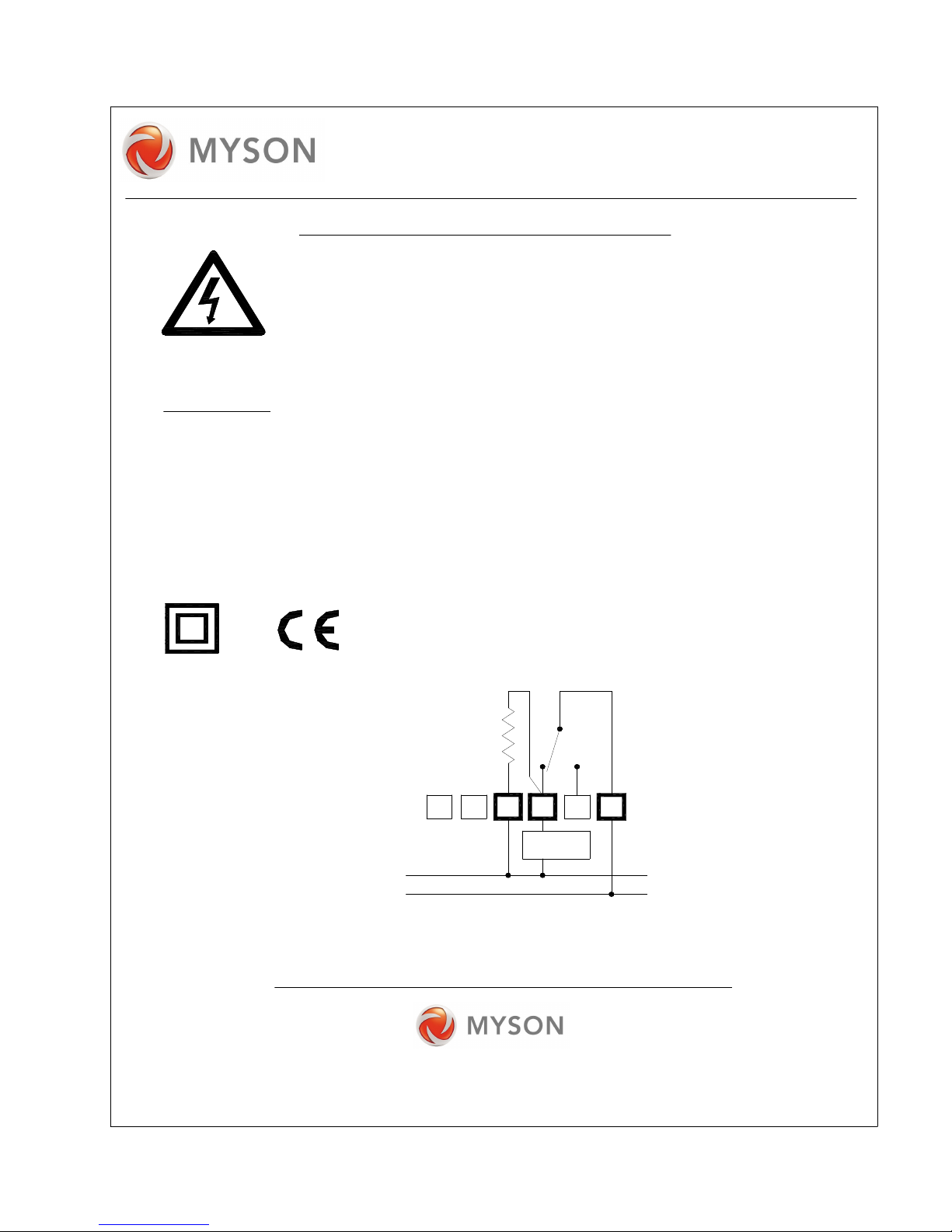
N
L
LOAD
4 3 1
HEATING
230V~
Switching D ifferential: 1.3
Ope rating Range: 6 to 30
Ambie nt Humidity: 5 to 95% Relative H um idity.
Ambie nt Temp era ture: 0 to 50
Enc losure Protection : IP2 0.
Enc losure In sulation: Cla ss II, (do uble insulated).
Switch Ratin g: 15(2.5 )A
Sup ply Voltage: 230V~, 50H z.
TECHNIC AL DATA.
Disconnect mains su pp ly before re mo ving cover.
PRECAUT IO NS AG AINST ELECTR IC SHOC K HAZAR D.
Installation & maintena nce m ust b e carried out by suitably q ualified
personne l and in accordance with current IEE wiring regulation s.
Fun ction: Control o f room temperatu re by electrical s wit ching of control circuit.
Con struction: Electro M ec hanical Switch .
C.
o
C.
o
C.
o
Pollution Sit uat ion: Normal.
CIRCUIT WIRING DIAGRAM.
Do not m ou nt to unearthed m etal or metalised surfaces.
INSTALLATION INSTRUCTION.
Fixed wiring in sta llation m us t be e mp loyed . A class 'A ' switch, (having
con tact separation of at le ast 3m m in all poles) m ust b e incorp orated in the fixed wiring as a
means of disconn ecting the supply. U se a fus e rated at 3 amp s to protect the syste m.
Installatio n Details : See w irin g diagra m below an d installation instructio ns overleaf.
SC19 59: Rev ision 2.
MYS ON LT D, EAST ERN AV ENUE,
SALE S OFFI CE No. : 0845 40 2 3434
TYN E & WE AR, NE1 1 0PG
MYS ON CO NTROLS
TEA M VALL EY, GAT ESHEAD ,
Page 2
20
30
2
5
1
0
1
5
123
UP
46 5
1
5
10
2
5
30
3 2 1
20
6 5
2
5
30
3 2 1
20
4
1
5
1
0
20
6 5 4 3 2 1
1
5
1
0
2
5
30
56 420123
30
2
5
1
0
1
5
346 5 2 1
20
30
2
5
1
0
1
5
4
5
6
1
3
2
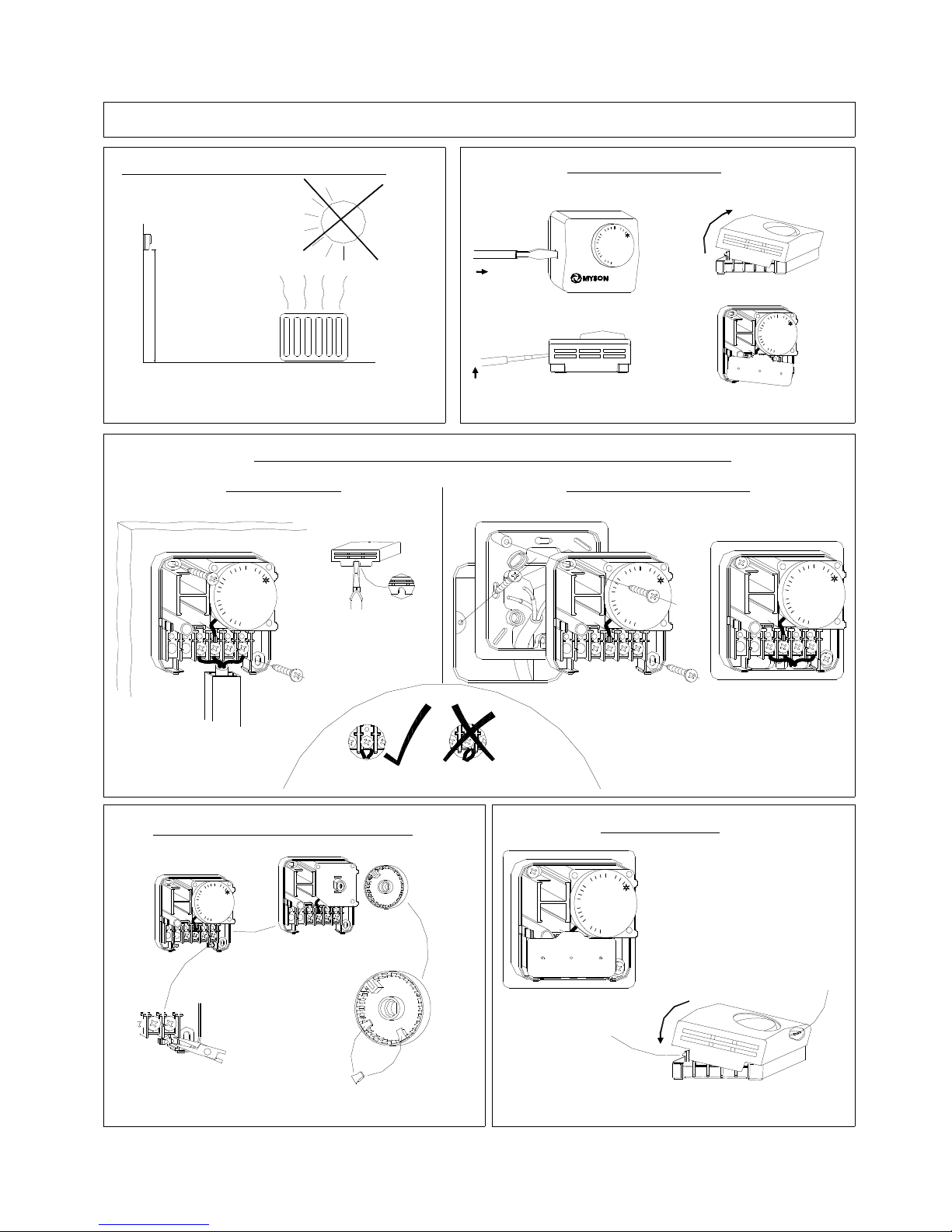
COVER REMOVAL.
slot on the side of th e thermostat .
2: Leve r screwdrive r upwards to prise
3: Rota te cover free of the therm ostat.
4: Re move the term inal cover.
Wall Fixing. (Choose either Surface or Concealed Wire Fixing.)
Surface Fixing.
Concealed Wire Fixing.
4: Use pliars to rem ove 'break-out '
3: Wir e as indicate d in wiring di agram overleaf .
2: Rou te the cable in cable trun king as shown .
1: Fix thermostat t o wall using t wo screws as shown.
4: Wir e as indicate d in wiring di agram overleaf .
2: Rou te the cable through the backplate an d beneath the
3: Fix the thermost at to the bac kplate using two screws a s shown.
1: Fix backplate to wall box usi ng two screws as shown.
FITTING TEMPERATURE LIMITS.
3: Fit t he limits to t he rear of th e dial as shown .
2: Use a snips to c ut the two limi ts
4: Refit the dial to th e thermostat ensuring tha t the flat of th e
1: Rem ove the dial from the ther mostat
1-1.5m
POSITIONING OF THERMOSTAT.
from th e cover so a s to allow
1: Inse rt blade of s crewdriver in to the clip
the cov er off the clip .
cover f it over surfac e cable.
termina ls of the the rmostat.
4 3
4 3
(recom mended pra ctice)
REASSEMBLY.
1
0
30
2
5
20
1
5
6 34 2 15
1: Fit t erminal cove r over the term inals.
2: Loca te cover ove r thermostat so that the t wo locating
3: Rota te cover dow nwards so th at it engage s on the
thermo stat locating protrusion.
thermos tat clip.
matchin g receptacle s on the ins ide of the cove r.
protrusi ons of the th ermostat alig n with their
thermos tat clip.
by gent ly prising it forward.
away from the ther mostat.
dial hub lines up with the flat of th e thermostat spindle.
INSTALLATION INSTRUCTION.
2: Do n ot locate in a position di rectly expose d to heat fro m the radia tor, sunlight, or other heat
1: Loca te the therm ostat at a he ight betwee n 1 and1.5 m etres from the floor.
3: In th e case of a room with a single radiat or, locate on the wall adj acent to the wa ll of the radiato r
4: In th e case of a room with m ultiple radiat ors, try to lo cate on a wall central to all ra diators
sources
Page 3

 Loading...