

Page 1
PRESS TO ALTER YOUR “HIGH” TEMPERATURE
PRESS BOTH TOGETHER TO SET/VIEW CLOCK
PRESS TO ALTER YOUR “MID” TEMPERATURE
PRESS TO ALTER YOUR “LOW” TEMPERATURE
+
PRESS HERE
MPRT MS
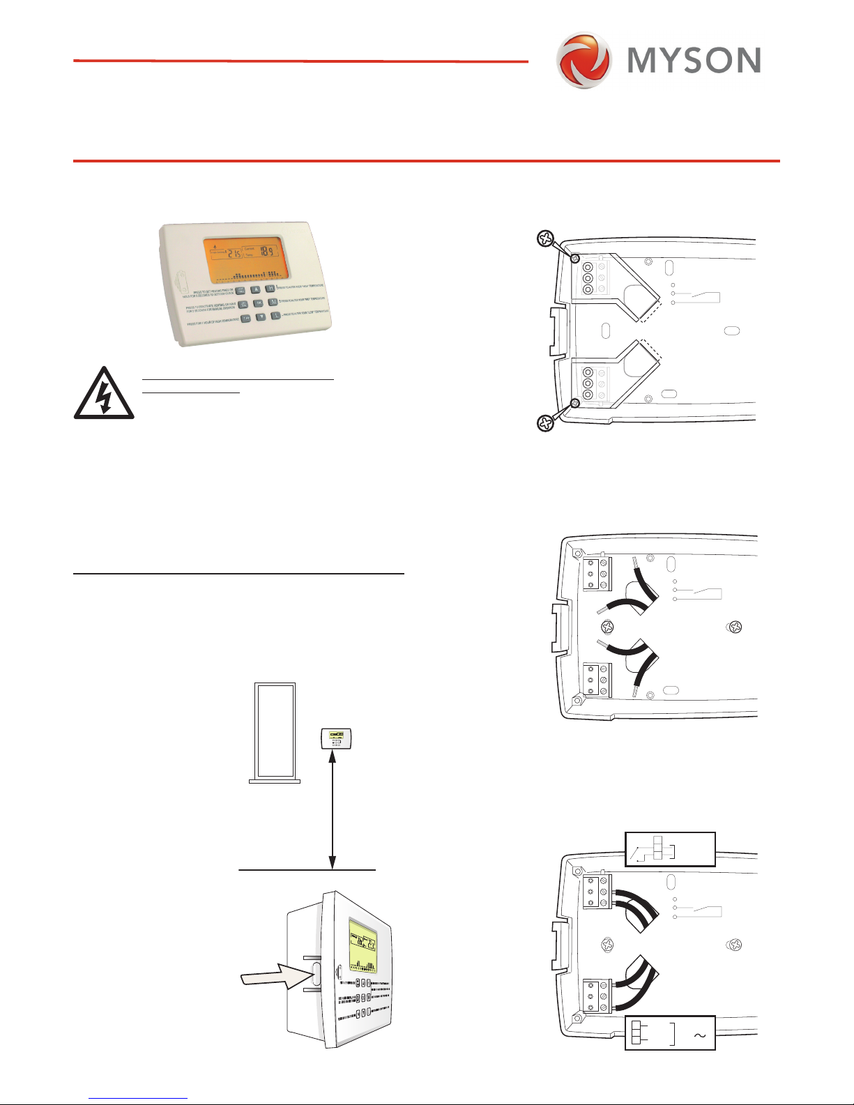
PROGRAMMABLE ROOM THERMOSTAT
The MPRT MS is a programmable room thermostat. It senses the
room temperature and if heat is called for, it
activates the heating.
WIRING THE MPRT MS.
The MPRT MS is wired directly to the
heating equipment and powered
directly from the main voltage supply.
MPRT MS
INSTALLATION INSTRUCTION
LOCATING THE ROOM UNIT
The MPRT MS is mounted using the two screws provided.
WHEREVER the Room Unit is mounted/used it should be out of
direct sunlight, out of draughts, and clear of any heat source (e.g.
radiators, fires or electronic equipment). For optimum use the unit
should be sited between 1 and 1.5metres from the floor.
OK
H
M
L
HEAT
TIME
S
PRESS TO ALTER YOUR HEATING TIMES
PRESS TO DEAC
TIVATE HEATING, OR HOLD
FOR 5 SECONDS FOR MANUAL OVERRID
E
PRESS FOR 1 HOUR OF HIGH TEMPERAT
URE
PRESS TO ALTER YOUR “HIGH” TEMPERAT
URE
PRESS BOTH TOGETHER TO SET/VIEW CLOC
K
PRESS TO ALTER YOUR “MID” TEMPERATUR
E
PRESS TO ALTER YOUR “LOW” TEMPERA
TURE
OFF
MA
N
1 Hr
High Setting
Current
Temp
02 46 810 12 141618 20 2224
OK
H
M
L
HEAT
TIMES
PRESS TO ALTER YOUR HEATING TIMES
PRESS TO DEA
CTIVATE HEATING, OR HOLD
FOR 5 SECONDS FOR MANUAL OVERRIDE
PRESS FOR 1 HOUR OF HIGH TEMPERATURE
PRESS TO ALTER YOUR “HIGH” TEMPERATURE
PRESS BOTH TOGETHER TO SET/VIEW CLOC
K
PRESS TO ALTER YOUR “MID” TEMPERATUR
E
PRESS TO ALTER YOUR “LOW” TEMPERATURE
OFF
MAN
1 Hr
High Setting
Current
Temp
02 46 810 12 141618 20 2224
(1.0 - 1.5) m
Release the MPRT MS from its
base by pressing at the arrow.
STEP 1.
Remove terminal covers by removing terminal screws.
STEP 2.
Thread control and power input wires through the knock-outs and
attach base plate to the wall.
STEP 3.
Connect control wires to terminals 2 and 3.
Connect power input wires to terminals 4 and 6.
PRECAUTIONS AGAINST ELECTRIC
SHOCK HAZARD.
Disconnect mains supply before moving cover.
Installation and maintenance must be carried out by suitably
qualified personnel and in accordance with current IEE wiring
regulations.
Do not mount to unearthed metal or metalised surfaces.
Fixed wiring installation must be employed. A class ’A’ switch,
(having contact seperation of at least 3mm in all poles) must be
incorporated in the fixed wiring as a means of disconnecting the
supply. Use a fuse rated at least 3 amps to protect the system.
To heating
equipment
1
5
1
2
3
5
4
6
1
2
3
0
C
Power input
230 V
AC
50Hz
Live
Neutra
l
4
5
6
1
2
3
To heating
equipment
c
To heating
equipment
er
1
2
3
1
2
3
5
4
6
1
2
3
To heating
equipment
c
To heating
equipment
MPRT Back Cov
er
To heating
equipment
1
5
1
2
3
5
4
6
1
2
3
0
C
Power input
230 V
AC
50Hz
Live
Neutra
l
4
5
6
Page 2

MYSON CONTROLS
MYSON LTD., EASTERN AVENUE,
TEAM VALLEY, GATESHEAD,
TYNE & WEAR,
NE11 0PG
SALES OFFICE No. 0845 402 3434
IN ACCORDANCE WITH OUR POLICY OF CONTINUAL PRODUCT IMPROVEMENT WE
RESERVE THE RIGHT TO AMEND THE SPECIFICATION OF THESE PRODUCTS WITHOUT
PRIOR NOTIFICATION.
SETUP FOR SMART-START.
To toggle the Smart-Start function between enabled and disabled,
hold and down for 10 seconds. The button can now be
used to toggle Smart-Start between active and deactivated.
CONFIGURING FOR WEEKLY OR
DAILY TIMING.
To toggle between weekly or daily time settings, hold and
down for 10 seconds. The button can now be used to toggle
between enabled and disabled.
CONFIGURING FOR GAS OR OIL
To toggle between Oil or Gas hold and down for 10
seconds. The L button can be used to toggle between
Oil and Gas.
H
OK
H
M
L
OK
H
M
L
HEAT
TIMES
OF
F
MA
N
1 Hr
H
OK
H
M
L
H
HEAT
TIMES
TECHNICAL DATA:
Precision of measured temperature: 0.1oC
Set temperature range: 6oC to 32oC
Electrical Protection: Class II
Ingress Protection: IP30
Power Supply: 230 Vac
+
/- 10% , 50 Hz
Statutory Compliance: EMC 89\336\EEC,
LVD 2006\95\EEC
Pollution Situation: Normal
Software Class: A
Output Relay Rating: 8(3)A 250Vac
ACTIVATING THE MPRT MS.
Remove the plastic strip that is preventing the battery connection
in the battery compartment.
The LCD should display as shown below.
Re-assemble the unit to the base by first locating the right hand
side and then closing the left .
MON
TUE WED
THU FRI SAT SU
N
0 2 4 6 8 10 12 14 16 18 20 22 24
TO ACCEPT & CO NTINUE PRESS OK
TO CHANGE VALUE PRESS OR
FOR LOW PRESS “L”, FOR MEDIUM PRESS “M”, FOR HIGH PRESS “H”
TO ACCEPT & CONTINUE PRESS OK
Low Setting
Current
Temp
0 2 4 6 8 10 12 14 16 18 20 22 24
12 14 16 18 20 22 24
SAT SUN SMART START
12 14 16 18 20 22 24
SAT SUN SMART START
0 2 4 6 8 10
0 2 4 6 8 10
0 2 4 6 8 100 2 4 6 8 10
STEP 4.
It is essential that the terminal cover must be replaced and
secured with the screws removed in STEP 1.
H
OK
H
M
L
SC2450 - R1
To heating
equipment
To heating
equipment
1
5
1
2
3
5
4
6
1
2
3
0
C
Power input
230 V
AC
50Hz
Live
Neutra
l
4
5
6
 Loading...