


COMPLETE HEATING SOLUTIONS
KICKSPACE® 500E ECO
& 600E ECO
INSTALLATION & OPERATING MANUAL
PLEASE LEAVE THIS MANUAL WITH THE END USER

1.0 Safety Information
For MYSON KICKSPACE® 500E ECO & 600E
ECO, a fused electrical spur with a switch having
3mm separation on all poles must be provided in
an easily accessible position adjacent to the unit.
If the supply cord to the KICKSPACE® 500E ECO
or 600E ECO is damaged, it must be replaced
by the manufacturer, its service agent or similar
qualified persons in order to avoid a hazard.
This appliance can be used by children aged
from 8 years and above and persons with
reduced physical or mental capabilities or lack
of experience and knowledge if they have been
given supervision or instruction concerning the
use of the appliance in a safe way and understand
the hazards involved.
Children shall not play with the appliance.
Cleaning and user maintenance shall not be
made by children unless they are older than 8
years and supervised.
Keep the appliance and its cord out of reach of
children aged less than 8 years.
Children of less than 3 years should be kept away
from the unit unless continuously supervised.
Children aged from 3 years and less than 8 years
shall only switch on / off the appliance provided
that it has been placed or installed in its normal
operating position and they have been given
supervision or instruction concerning use of
the appliance in a safe way and understand the
hazards involved.
Children aged from 3 years and less than 8 years
shall not plug in, clean the appliance or perform
user maintenance.
WARNING: KICKSPACE® 500E ECO & 600E ECO models must be earthed.
WARNING: DO NOT cover the unit or obstruct the grille as this could give risk of fire.
1.0 Safety Information 02
2.0 Installation 03
3.0 Electrical Connection
03
4.0 Waste Disposal According to the
WEEE Directive (2012/19/EU) 03
5.0 Controls 04
6.0 Appendix 07
7.0 Eco Directive Characteristics 11
Contents
The KICKSPACE® 500E ECO & 600E ECO models MUST NOT be installed in a bathroom
or other similar high humidity area.
02
KICKSPACE
®
500E ECO & 600E ECO
CAUTION: Some parts of this product can
become very hot and cause burns. Particular
attention has to be given where children and
vulnerable people are present.
03
KICKSPACE
®
500E ECO & 600E ECO
1.02.03.04.0
2.0 Installation
l Before proceeding with the installation, the heating system
design must be considered and the unit correctly sized to
meet the heat loss requirements of the room.
l Before proceeding with the installation, unpack the carton
contents and check against the checklist below:
1. KICKSPACE
®
unit.
2. Instruction manual.
3. Warranty card.
4. Grille.
5. Screw fixing kit (with grille).
l This MYSON KICKSPACE
®
fan convector is designed for
installation in the cavity beneath kitchen cupboards in the
vacant floor space, or other similar locations.
l For KICKSPACE
®
500E ECO & 600E ECO a minimum of 25mm
clear headroom is required above the top of the KICKSPACE
®
when fitted.
l The unit should be mounted on a clean and level floor area
under the cupboard base.
l KICKSPACE
®
500E ECO & 600E ECO plinth mounting
(see Fig. 1) -
• The unit must be mounted on a suitable support.
• The support should be mounted on a clean and level floor
area under the cupboard base, and securely fitted.
• The top of the support must be level with the lower edge of
the cut-out when fitted.
l Decide the position of the KICKSPACE
®
, mark out and cut the
plinth to the dimensions using table on page 8.
l Position the KICKSPACE
®
under the cupboard in the required
location, with the front edge just behind the line of the plinth.
l Replace the plinth and bring the KICKSPACE
®
forward into
the opening so the front edge projects approximately 10mm
through the plinth.
l KICKSPACE
®
500E ECO & 600E ECO are fitted with a transit
cover to protect the electric element and to minimise risk
of electric shock prior to the grille being fitted. The cover
must only be removed with the electrical supply switched off
immediately prior to fitting of the grille.
l Align the grille and secure it to the unit with two screws
supplied (use the shorter screws). (See Fig. 2).
l Secure the unit/grille to the plinth with two screws supplied
(use the longer screws). (See Fig. 2).
l Complete the electrical installation, switch on and test the
KICKSPACE
®
(see Fig. 3).
l When installed in a kitchen consideration should be given to
storage of perishable goods in the cupboard above.
l No rear access to the unit shall be available after installation.
Waste disposal according to the WEEE Directive
(2012/19/EU). The symbol on the product label
indicates that the product may not be handled as
domestic waste, but must be sorted separately.
When it reaches the end of its useful life, it shall
be returned to a collection facility for electrical and electronic
products. By returning the product, you will help to prevent
possible negative effects on the environment and health to
which the product can contribute if it is disposed of as ordinary
domestic waste. For information about recycling and collection
facilities, you should contact your local authority/municipality or
refuse collection service or the business from which you purchased
the product. Applicable to countries where this Directive has
been adopted.
3.0 Electrical Connection
4.0 Waste Disposal According to the WEEE Directive (2012/19/EU)
l The electrical installation must comply with local or national
wiring regulations.
l This KICKSPACE
®
500E ECO is supplied fitted with a 2.0 metre
1.0mm
2
cord.
l This KICKSPACE
®
600E ECO is supplied fitted with a 2.0 metre
1.5mm
2
cord.
l For KICKSPACE
®
500E ECO & 600E ECO a fused electrical
spur with a switch having 3mm separation on all poles must be
provided in an easily accessible position adjacent to the unit.
l If the supply cord to KICKSPACE
®
500E ECO or 600E ECO is
damaged, it must be replaced by the manufacturer, its service
agent or similar qualified persons in order to avoid a hazard.
WARNING: KICKSPACE® 500E ECO & 600E ECO models must be earthed.
Do not energise the electrical supply until the remaining stages of the installation have been completed.
04
5.0 Controls
KICKSPACE
®
500E ECO & 600E ECO
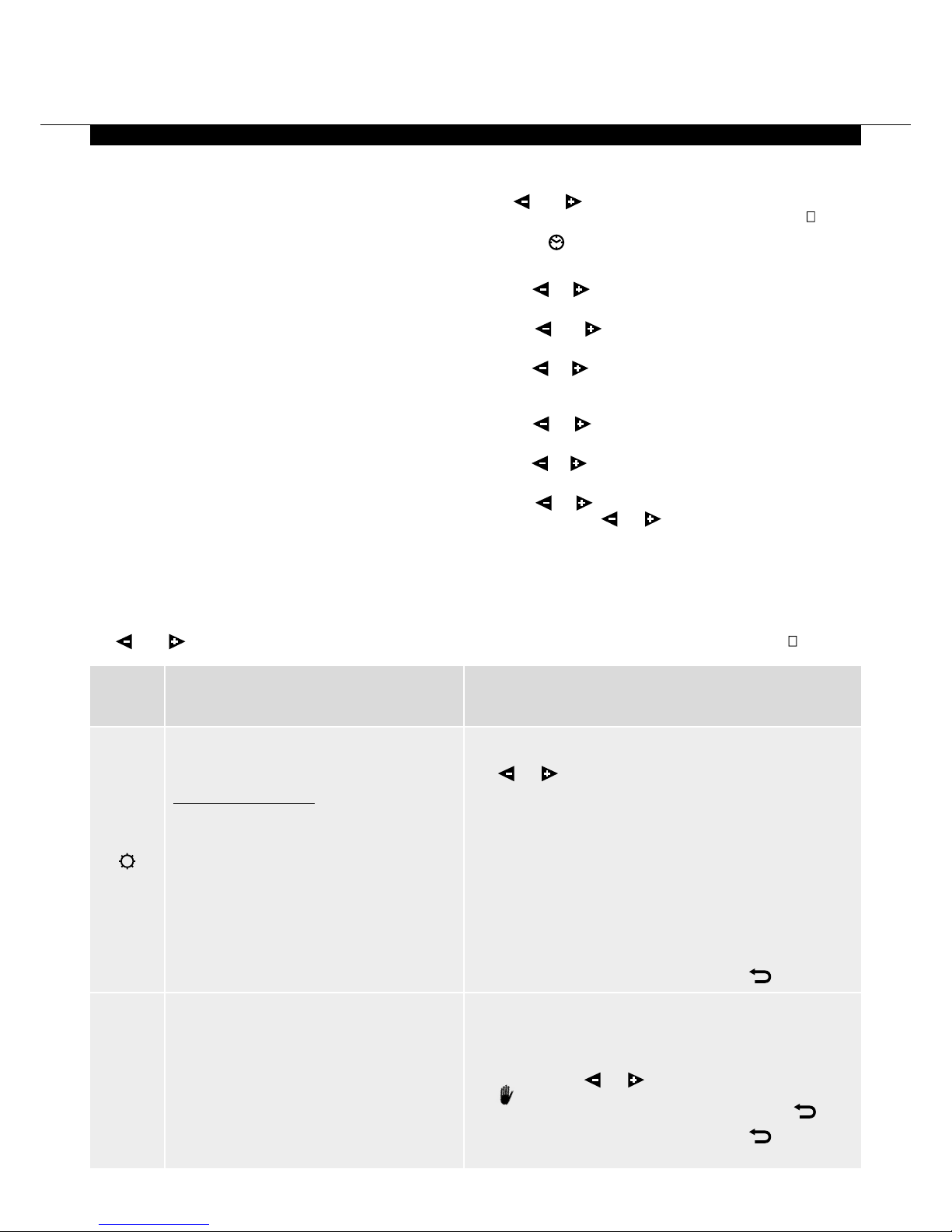
Function AdjustmentDescription
The display will show the ambient temperature.
Press OK, set temperature will begin to blink.
Use
or
to adjust the required room temperature.
Press OK to confirm.
The ambient room temperature will then display.
Default setting +21°C
Max temp setting +30°C
Min temp setting +5.5°C
Note: The thermostat has a LED indicator that will change colour
depending on the following:
≤21.0°C = Green
21.5°C - 24.0°C = Orange
≥24.5°C = Red
Note: To see the set temperature simply press
.
See page 6 for ‘Programme Mode’ setup.
Note: When in AUTO mode it is possible to override by
selecting a new temperature. To do this while in AUTO mode,
press (OK), the temperature will begin to blink, change the
temperature using
or
and press (OK) to confirm.
The
symbol will display showing the override and this will
last for 2 hours. To remove the override you can press
.
Note: To see the set temperature simply press
again.
Comfort Mode
Provides room temperature control for when
the room is occupied (see Fig. 3).
Heating mode – Electric
To enter this mode:
• Set the fan only/off/heating switch
to heating (red dot)
• Set the output switch to position I
• Select the fan speed switch to position I
The unit will now run on low speed.
To operate the 500E ECO at 2kW or the
600E ECO at 3kW:
• Set the output switch to position II
The unit will now run on high speed.
Automatic Setting
The unit will run according to one of the 9
preset timed programmes, or one of the 4 user
defined programmes.
Auto
This unit is controlled by the switches on the front of the unit
(see Fig. 3) and a wireless programmable thermostat.
The wireless programmable thermostat includes many features
and also ensures the electric KICKSPACE
®
products comply with
the Commision Regulation (EU) 2015/1188. These features
can be identified on the display of the wireless programmable
thermostat (see Fig. 4).
Locating the Wireless Programmable Thermostat
The wireless programmable thermostat includes a flip out stand
and can be freestanding in a suitable location. Alternatively it
can be wall mounted, fitting instructions can be seen in Fig. 5.
Wherever the wireless programmable thermostat is mounted/
used it should be out of direct sunlight, away from draughty
areas and clear of any potential heat sources. For optimum use
the thermostat should be fitted at a height of 1.5m from the
floor (see Fig. 6).
First use of the Wireless Programmable Thermostat
Remove the plastic insulator from the battery compartment in
the remote control. Hold OK for 10 seconds until ‘rF ini’ appears.
Press OK again and ‘ini’ flashes until the unit has paired with
the KICKSPACE
®
. The remote control reverts back to its normal
screen when paired.
Setting the date and time
Use
and
keys to choose from the following parameters.
A function is selected when the icon is surrounded by .
1. Select and press OK.
2. Press (OK) the hours will begin to blink.
3. Use
or
to change the hour and press (OK) to confirm,
the minutes will then begin to blink.
4. Use
or
to change the minutes and press (OK) to
confirm, the day number will then display.
5. Use
or
to change the day number, with Monday being
1 and press (OK) to confirm, the date and month will then
display and the day will begin to blink.
6. Use
or
to change the day and press (OK) to confirm,
the month will then begin to blink.
7. Use
or
to change the month and press (OK) to confirm,
the year will then display and begin to blink.
8. Use
or
to change the year and press (OK) to confirm,
and then scrolll
or
to go back to the main menu.
Operating Modes
Use
and
keys to choose from the following parameters. A function is selected when the icon is surrounded by .
 Loading...