

mySmart MWS7 Product Manual
page
Section Contents Page
1 Dimensions 1
2 Description and operation 2
3 Wiring and xing 3
4 Installation/setting up 4
5 Programming 5
6
Wiring diagrams
7
7
Detection patterns
10
8
Fault nding
12
9
Specication
12
10
Part numbers
12
80°
60°
40°
20°
0°
90°
10°
30°
50°
70°
90°
10°
30°
50°
70°
80°
60°
40°
20°
80°
60°
40°
20°
0°
90°
10°
30°
50°
70°
90°
10°
30°
50°
70°
80°
60°
40°
20°
MWS7
Microwave Aisle Sensor
230VAC 10A
www.cpelectronics.co.uk
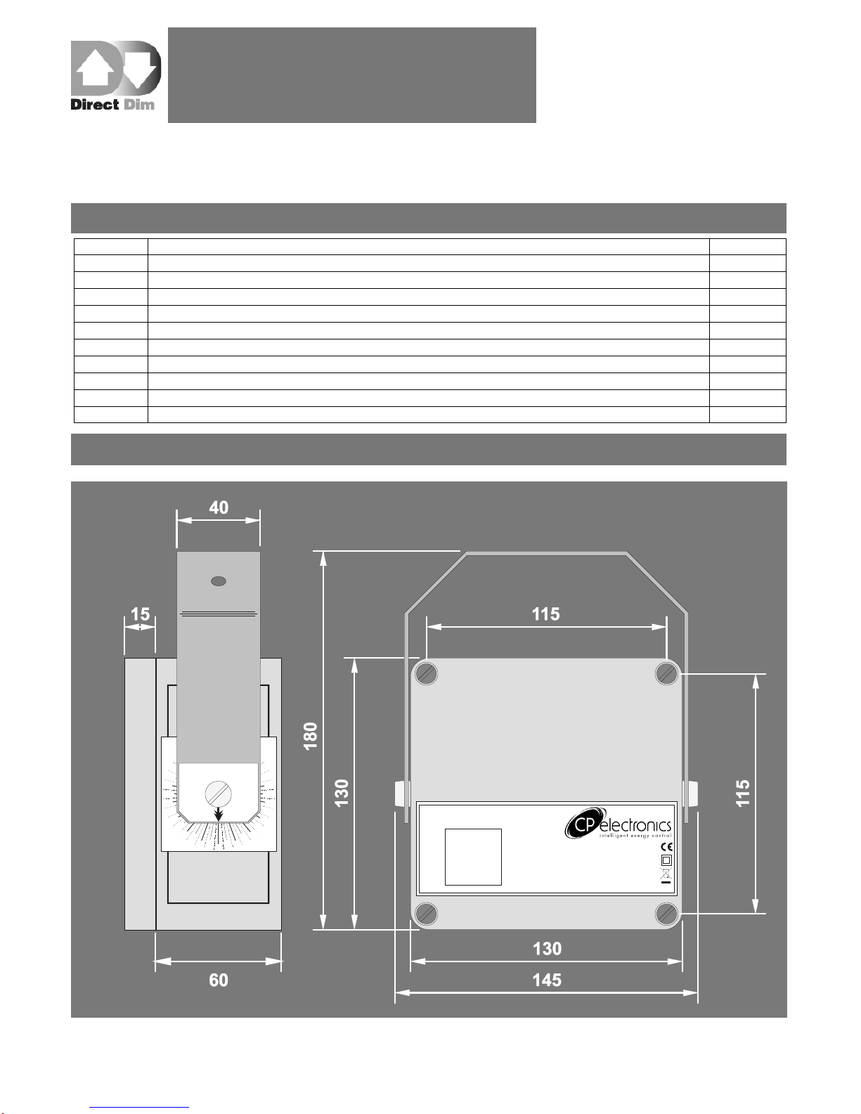
1. Dimensions
Contents
Product Guide
MWS7
Direct Dim Microwave Aisle Occupancy Detector
page 2
SENSITIVITY LUX
TIME RANGE
LOW HIGH DARK LIGHT
SHORT LONG NEAR FAR
www.cpelectronics.co.uk
MWS7
Microwave Aisle Sensor
DSI/DALI (+)
DSI/DALI (-)
N
L/OUT
L
LVS (COM)
LVS (NC)
LVS (NO)
GND
EXT. LUX
GND
SLAVE
GND
SW. DOWN
SW. UP
JUMPER SETTINGS
Mains Relay (L/OUT)
Low Voltage Relay (LVS)
Perm. ON
Auto.
ON/OFF
Perm. OFF
E
ISOLATED SWITCH
INPUTS ONLY!
230V MAINS ONLY!
230VAC 10A
NOT USED
RELAY OUT
24V MAX!
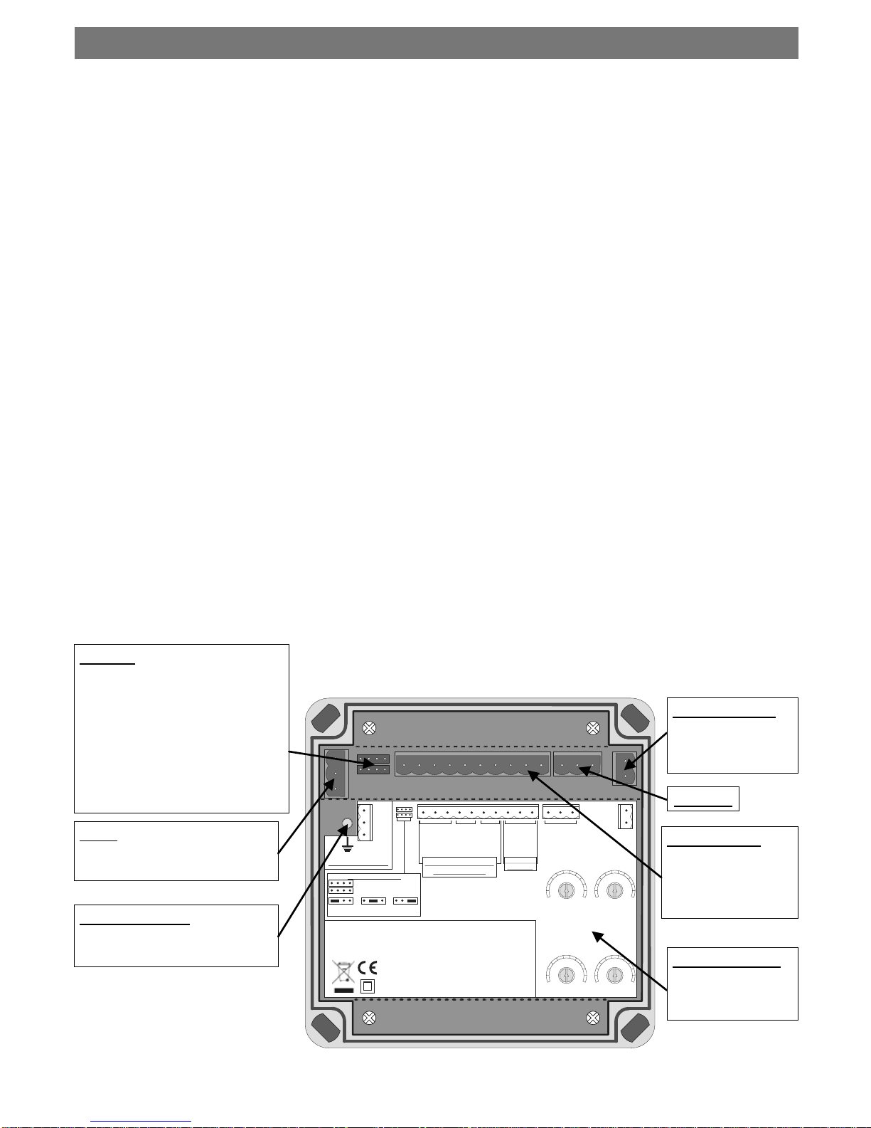
Jumpers
Used to set the states of the
switched live output and low
voltage relays in three different
states (‗Permanently ON‘,
‗Automatic ON/OFF‘ (controlled by
sensor detection) and
‗Permanently OFF‘). It is advised
that if a relay channel is not
being used it is set to OFF.
Mains
Power in and switched live out.
Earth Connection
MUST be connected.
Dimming Output
DSI/DALI output for
dimming control of
luminaires.
Not Used
Inputs/Outputs
Switch inputs (must
be isolated contacts)
and low voltage relay
outputs.
Manual adjusters
Sensor parameters
(sensitivity, lux, time
and range).
The MWS7 is a microwave occupancy detector that provides automatic control of lighting loads, and is
especially suited for warehouse applications. When a person or fork lift truck enters the aisle or corridor,
the sensor will turn the lights on, or raise the level of light output. After a pre-determined period, the lights
will turn off or dim down. The detector uses advanced microwave technology that allows the range of
detection to be accurately set, irrespective of whether the object is a person or a fork lift truck (a common
problem with other types of detector is that larger objects are picked up at longer distances, making
accurate setup impossible). A further benefit of the MWS7 is that it has good immunity to vibration.
Three output channels are provided:
Switching channel with a high power relay
Switching channel with a low voltage, low power isolated contact
Dimming channel capable of controlling up to 20 DSI or DALI ballasts
The detector has a built in photocell that measures the overall light level in the detection area. This can be
used to turn the lights on and off when natural light is sufficient, or on dimming systems to calculate the
correct output for the luminaires to achieve a preset lux level (maintained illuminance). The dimming
channel can also be used to set the luminaires to a ―standby‖ dim level rather than switching off
completely.
Input terminals are provided to give the following features:
Manual override of the dimming levels and switched outputs
Slave detector input—for use in dimming systems
External lux input—disables the output when there is sufficient natural light
Manual adjustments can be made to the sensitivity, range, lux and time settings using the physical
controls inside the sensor. Alternatively, an integral infra-red sensor in the unit allows the unit to be
programmed using the optional DD-LCDHS-LR programming handset, working to a range of 15m. This
gives complete flexibility over many of the operating parameters.
2. Description and Operation

page 3
Wire the products using the diagrams shown in section 6.
Do not exceed the maximum load and number of dimming connections as detailed in the specification
(section 9).
To control one or more loads from multiple sensors, wire two or more sensors in parallel using the Live,
Neutral and Switched Live (L/Out) connections only, or wire using the slave input terminals. The
dimming connection(s) from the luminaires must however only be wired to one of the MWS7 sensors.
The sensor should be sited so that the occupants of the room fall inside the detection pattern shown in
section 7. It is recommended for a single-sensor scenario that the sensor is sited near to one end of the
corridor or aisle and angled to provide maximum coverage of the desired area. For a multi-sensor
scenario, it is recommended that the sensors be placed near the centre of the corridor or aisle and
angled correctly to provide maximum coverage of the desired area.
Note that the fully adjustable detection range of the MWS7 provides a well-defined detection area that
extends radially from the sensor. It is therefore advantageous for the sensor to be mounted as low as
possible to provide the minimum range variation for objects of different heights (illustrated in section 7).
Note that the higher the sensor is installed, the effective detection range will become shorter.
Note also that the spread angle of the detection beam shown in section 7 is defined as the area of
maximum sensitivity. Detection is still possible outside these angles, but with a significantly reduced
sensitivity.
Installation Recommendations
Do not site so that the sensor is pointing at any fluorescent lighting
Site the sensor as far away as possible from the surface of metal objects
Site so that the sensor has an un-obstructed view of the desired coverage area
3. Wiring & Fixing

page 4
Warning. This device works at mains potential. Be sure to take care when working with electricity.
1. Isolate the mains supply to the circuit at the main consumer unit whenever working on the
connections to the sensor.
2. Make sure the load is connected and in working order.
3. Connect the sensor via the plug-in terminal blocks. Live supply to the L terminal, load to the L/
OUT terminal and Neutral to the N terminal, all on the green terminal block. Earth to the E
terminal stud on the sensor body. Dimming and external input connections should be made via
the plug-in terminal blocks as required according to the applicable wiring diagrams shown in
section 6.
4. Two relay channels are provided, switched live and low voltage—if the channel is being used, set
the jumper to ―Auto‖, if it is not being used, set the jumper to ―OFF‖. To verify that the channel is
working, the jumper can be set to ―ON‖.
5. Set the sensitivity to maximum (fully clockwise) and range to the desired distance. Note that the
range varies between 5m (minimum) and 30m (maximum) when using the adjusters. Alternatively,
use the DD-LCDHS-LR to set these parameters.
6. Set the sensor to the appropriate angle then apply power and vacate the area for a minimum of 30
seconds while the sensor builds a ‗picture‘ of the area. Note that every time the sensor‘s range is
changed or the sensor is power-cycled, this step must be observed to ensure the proper operation
of the sensor.
7. Walk towards the sensor until the load comes on, to find the detection range. The use of the ‘Walk
Test‘ setting using the DD-LCDHS-LR will aid in finding this point by observing the flashing LEDs
within the sensor.
8. Tune the sensor range to the desired point by adjusting the range and repeating from step 6. Note
that a large metallic object may be detected up to 2m further away than a person - sufficient
adjustment must therefore be made to account for this.
9. Once the range has been set correctly, the sensitivity should be reduced as far as possible to a
point which still gives reliable detection at the same range.
10. For dimming applications, set the light output level by using the lux adjustment.
During operation the output level varies very gradually. However when the lux level is
changed the unit automatically enters setup mode: in this mode the output level varies
rapidly. After the setup time the unit reverts to normal
When adjusting the output, allow the output level to settle by changing very gradually
To disable the maintained illuminance function completely, set the lux level to maximum
11. Select the desired time-out using the adjuster or handset.
12. Other parameters can be set using the handset, see section 5 for details.
View of the adjusters inside the unit
SENSITIVITY LUX
TIME RANGE
LOW HIGH DARK LIGHT
SHORT LON G NEAR FAR
4. Commissioning
 Loading...