

Myryad MXV-3000 Owners manual
Myryad Systems Ltd.
2 Piper’s Wood
Waterberry Drive
Waterlooville Po7 7XU
Tel: +44 (0) 23 9226 5508
Fax: +44 (0) 23 9223 1407
info@myryad.co.uk
For further information,
please contact Myryad
direct or visit:
www.myryad.co.uk
Progressive Scan
DVD-Video Player
Owner’s manual
MXV 3000
Part Number: 0ST0012220 A

SAFETY INFORMATION
TO REDUCE THE RISK OF FIRE AND ELECTRIC SHOCK, DO NOT EXPOSE THIS UNIT TO
RAIN OR MOISTURE.
IMPORTANT SAFEGUARDS
1.
2.
3.
4.
5.
6.
7.
8.
9.
Read andFollow Instructions- All the safety and operation instructions
should be read before the video product is operated. Follow all
operating instructions.
Retain Instructions- The safety and operating instructions should be
retained for future reference.
Heed all Warnings-Comply with all warnings on the video product and in
the operating instructions.
Polarization- This video product is equipped with a polarized alternating
-current line plug . This plug will fit into the power outlet, try reversing
the plug. If the plug still fails to fit, contact your electrician to replace
your obsolete outlet. To prevent electric shock, do not use this polarized
plug with an extension cord, receptacle, or other outlet unless the
blades can be fully inserted without blade exposure. If you need an
extension cord, use a polarized cord.
Power Sources- This video product should be operated only from the
type of power source indicated on the marking label. If you are not sure
of the type of power supply to your home, consult your video dealer or
local power company. For video products intendedto operate from
battery power, orother sources, refer to the operating instructions.
Overloading- Do not overload wall outlets or extension cords as this can
result in a risk of fire or electric shock. Overloaded AC outlets, extension
cords, frayed power cords, damaged or cracked wire insulation, and
broken plugs are dangerous, They may result in a shock or fire hazard.
Periodically examine the cord, and if its appearance indicated damage
or deteriorated insulation, have it replaced by your service technician.
Power-Cord Protection- Power-supply cords should be routed so that
they are not likely to be walked on or pinched by items placed upon or
against them, paying particular attention to cords at plugs, convenience
receptacles, and the point where they exit from the video product.
Ventilation- Slots and openings in the case are provided for ventilation
to ensure reliable operation of the video product and to protect it from
overheating. These openings must not the blocked or covered. The
openings should never be blocked by placing the video product on a
bed, sofa, rug, or heat register. This video product should not be placed
in a built-in installation such as a book case or rack, unless proper
ventilation is provided or the video product manufacturer's instructions
have been followed.
Attachments- Do not use attachments unless recommended by the
video product manufacturer as they may cause hazards.
:
To reduce the
risk of fire and electric shock, do
not remove the cover (or back) of
the unit. Refer servicing only to qualified service personnel.
The lightning flash with arrowhead symbol, within an equilateral
triangle, is intended to alert the user to the presence of uninsulated
"dangerous voltage" within product's enclosure that may be of
sufficient magnitude to constitute a risk of electric shock.
The exclamation point within an equilateral triangle is intended to
alert the user to the presence of important operation and servicing
instructions in the literature accompanying the appliance.
WARNING: TO REDUCE THERISK OF FIRE OR ELECTRIC SHOCK, DO
NOT EXPOSE THISAPPLIANCE TO RAIN OR MOISTURE.
CAUTION: TO PREVENTELECTRIC SHOCK, MATCH WIDE BLADE OF
PLUG TO WIDE SLOT, FULLY INSERT.
In addition to the careful attention devoted to quality standards
in the manufacture of your video product, safety is a major factor
in the design of every instrument. However, safety is your
responsibility, too. This sheet lists important information that will
help to assure your enjoyment and proper use of the video
product and accessory equipment. Please read them carefully
before operation and using your video product.
Installation
Water and Moisture- do not use this video product near water for example,
near a bath tub, wash bowl, kitchen sink or laundry tub, in a wet basement,
or near a swimming pool and the like. Caution: Maintain electrical safety.
Powerline operated equipment or accessories connected to this unit should
bear safety certification mark on the accessory itself and should not be
modified so as to defeat the safety features. This will help avoid any danger
and should not be modified so as to defeat the safety features. This will help
avoid any potential hazard from electrical shock or fire. If in doubt, contact
qualified service personnel.
Accessories- Do not place this video product on an unstable cart, stand,
tripod, bracket, or table. The video product may fall, causing serious injury
to a child or adult as well as serious damage to the video product. Use this
video product only with a cart, stand, tripod, bracket, or table recommended
by the manufacturer's or sold with the video product.Any mounting of the
product should follow the manufacturer's instructions and use of a mounting
accessory recommended by the manufacturer.
A video productand cart combination should be moved with care. Quick
stops, excessive force, and uneven surfaces may cause the video product
and cart combination to overturn.
Outdoor Antenna Grounding- If an outside antenna or cable system is
connected to the video product, be sure the antenna or cable system is
grounded so as to provide some protection against voltage surges and
built-up static charges. Section 810 of the National Electrical Code,
ANSI/NFPANo.70-1984 (Section 54 of Canadian Electrical Code, Part1)
provides information with respect to proper grounding of the mast and
supporting structure, grounding of the lead-in wire to an antenna-discharge
unit, connection to grounding electrodes, and requirements for the
grounding electrode.
Power Lines-An outside antenna system should not be located in the
vicinity of overhead power lines, other electric light or power circuits, or
where it can fall into such power lines or circuits. When installing an outside
antenna system, extreme care should be taken to keep from touching or
approaching such power lines or circuits, as contact with them might be
fatal. Installing an outdoor antenna can be hazardous and should be left to a
professional antenna installer.
Cleaning- Unplug this video product from the wall outlet before cleaning.
Do not use liquid cleaners or aerosol cleaners. Use a damp cloth for cleaning.
Objects that may touch dangerous voltage points or "short-out" parts could result
in a fire or electric shock. Never spill liquid of any kind on the video product.
Lightning-For added protection for this video product during a lightning storm, or
when it is left unattended and unused for long periods of time, unplug it from the
wall outlet and disconnect the antenna or cable system. This will prevent damage
to the video product due to lightning and power line surges.
Servicing-Do not attempt to service this video product yourself, as opening or
removing covers may expose you to dangerous voltage or other hazards. Refer all
servicing to qualified service personnel.
Conditions Requiring Service-Unplug this video product from the wall outlet and
refer servicing to qualified service personnel under the following conditions:
A. When the power-supply cord or plug is damaged.
B. If liquid has been spilled, or objects have fallen into the video product.
C. If the video product has been exposed to rain or water.
D. If the video does not operate normally by following the operating instructions.
Adjust only those controls that are covered by operating instructions.
Improper adjustment of other controls may result in damage and will often
require extensive work by a qualified technician to restore the video product
to its normal operation.
E. If the video product has been dropped or cabinet has been damaged.
F. When the video product exhibits a distinct change in performance-this
indicates a need for service.
Replacement Parts-When replacement parts are required, have the service
technician verify that the replacements he uses have the same safety
characteristics as the original parts. Use of replacements specified by the video
product manufacturer can prevent fire, electric shock, or other hazards.
Safety Check-Upon completion of any service or repairs to this video product, ask
the service technician to perform safety checks recommended by the
manufacturer to determine that the video product is in safe operating condition.
Wall or Ceiling Mounting- The product should be mounted to a wall or ceiling only
as recommended by the manufacturer.
Heat-The product should be situated away from heat sources such as radiators,
heat registers, stoves, or other products (including amplifiers) that produce heat.
Use
Service
Note to CATV system installer
This reminder is provided to call the CATV system installer's attention to
Section 820-40 of the NEC which provides guidelines for proper grounding
and, in particular, specifies that the cable ground shall be connected to the
grounding system of the building, as close to the point of cable entry as
practical.
10.
11.
12..
13.
14.
15.
16.
17.
18.
19.
20.
21.
22.
23.
CAUTION
NOTES

NOTES
SPECIFICATIONS
SETUP MENU
SMART MY-LINK
MYRYAD A/V REMOTES
TROUBLESHOOTING
22-24
25
26
27-28
29-30
FEATURES CONTENTS
This product incorporates copyright protection technology that is
protected by method claims of certain U.S. patents and other
intellectual property rights owned by Macrovision Corporation and
other rights owners. Use of this copyright protection technology
must be authorized by Macrovision Corporation, and is intended
for home and other limited viewing uses only unless otherwise
authorized by Macrovision Corporation. Reverse engineering or
disassembly is prohibited.
Page
Manufactured under license from Dolby Laboratories.
Dolby and the double-D symbol are trademarks of Dolby
Laboratories. Confidential Unpublished Works.
1992-1997 Dolby Laboratories.
All rights reserved.
C
The player has built in copyright
protection technology that
prevents copying from a DVD
disc to any media.
If a video recorder is connected to
the player, the video output image
will be distorted during recording.
INTRODUCTION
SYSTEM CONNECTION
GETTING STARTED
FUNCTION BUTTONS
About DVD
About MP3
About the player
Front panel
Rear panel
Remote control
Connecting to a TV set
Connecting to Progressive TV
Connecting to StereoAmplifier
Connecting to Digital Amplifier
Connecting to 5.1-Ready Amplifier
Play a disc
OSD-DVD
OSD - VCD/CD
MP3 mode
Kodak Picture mode
3-4
5
6
6
7
8
9
9
10
10
11
12
12
13
14
15-21
WARNING
IMPORTANT NOTICE
FEATURES
ESSENTIAL SETUP
1-2
DVD, CD, VCD, SVCDMP3, WMA,
Picture CD compatible
CD-R, CD-RW capable
DVD-R, DVD+R capable
PAL / NTSC color system
4:3 / 16:9 screen format select
Composite Video output
S-Video output
Y Pb Pr (Component) Interlaced Scan output
Y Pb Pr Progressive Scan output
Down-mix stereo output
Dolby Digital 5.1 decoded output
Dolby Digital digital output
DTS digital output
Multi Subtitle select
Multi Language select
Multi Angle select
On screen display menu
Video equalizer
6 speaker setup and pink noise test
Digital zooming
Fast scan forward / backward
Slow motion
Child lock
Auto screen saver
TV format:
Video output:
Audio output:
DVD features:
Other features:
1
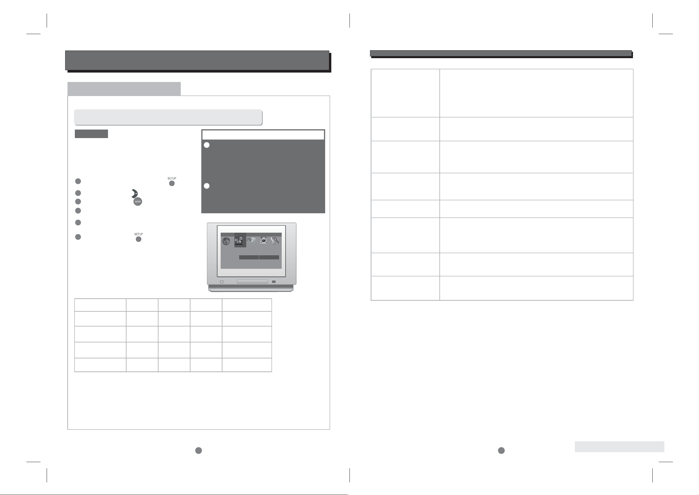
ESSENTIAL SETUP
Video outputs
In STOP mode, press button ,
setup menu appears.
SETUP
1
2
3
Highlight "Interlace Out" icon, press
button, sub menu appears.
ENTER
Highlight “S-Video”, "YCbCr" or “RGB” as desired
and press button. .
ENTER
The player is equipped with the following video output ports:
Press button to quit.SETUP
DEFAULT
Composite video (CVBS), S-Video, Y Pb Pr, SCART
YPbPr
Interlaced Scan output:
Progressive Scan output:
The factory default video output
setting is S-Video (interlaced scan)
In this mode the active video output ports are:
Composite video (CVBS) and S-Video.
To change the video output setting, after the system
connection is completed (see "SYSTEM
CONNECTION"), follow these steps:
Once the video “Interlace Out” has been set using
this procedure, the active video output ports are as
shown in the table below:
For Progressive Scan output
With no disc in the player press the PROG SCAN button on the remote control twice. Progressive Scan
component signals will be output from the Y/Pb/Pr jacks, whatever the previous “Interlace Out” video setting.
The same procedure is used to switch back to interlaced scan mode.
The composite video (CVBS) output
is active in all three video output
settings. Always connect the CVBS
signal to the TV if any problem is
experienced with obtaining a
picture.
When Progressive Scan has been
selected, no signal will be sent to
the CVBS, S-Video or SCART
outputs.
.........
.........
.........
.........
.........
.........
.........
.........
.........
.........
.........
.........
.........
.........
.........
.........
.........
.........
.........
.........
.........
.........
.........
.........
.........
.........
.........
.........
.........
.........
.........
.........
.........
.........
.........
.........
.........
.........
.........
.........
.........
.........
.........
.........
.........
.........
.........
.........
.........
.........
.........
.........
.........
.........
.........
.........
Language Video Audio 1 Audio 2 Rating
TV Screen
TV System
Interlace Out
Fade Mode
4:3 LetterBox
Auto
S-Video
Slow
S-Video
YCbCr
RGB
Press button highlight "Video" icon.RIGHT
Press button , sub-menu appears.ENTER
4
5
6
1
2
IMPORTANT NOTE
Video port -> CVBS S-Video Y Pb Pr RGB (SCART)
Interlace Out
S-Video
YCbCr
RGB
Yes
No
No
Yes
No Yes No
Yes
No No Yes
Yes
SPECIFICATIONS
30
Video outputs
(interlaced scan only)
Interlaced or
Progressive Scan
Audio outputs
(analogue)
Frequency Response
THD
Audio outputs
(digital)
Power input
Dimensions
Stock No: 0ST0012390 A (English)
Updated: 24th February ‘04
Composite
S-Video, Y
S-Video C
RGB
Component - Y / Pb / Pr
Digital-to-Analogue
Converter
Output level at 0 dB
Output impedance
CD:
DVD:
<0.01%
Coaxial
Optical
Standards
Sample rates
100-240 VAC ~50/60Hz
25W (Max)
Bodysize:W436xD286xH95 mm
Net weight : 5.5 Kg
1Vp-p/75
1Vp-p/75
0.3 Vp-p / 75 (PAL)
0.286 Vp-p / 75 (NTSC)
0.7 Vp-p /75
(plus 0.3V sync on Green)
1/0.52/0.52Vp-p/75
24 bit Delta-Sigma
2.0 Vrms
330
75
Toslink optical coupler
PCM, Dolby Digital, DTS
Up to 96 kHz
W
W
W
W
W
W
W
W
SPECIFICATIONS
20Hz - 20kHz (EIAJ) +/- 0.5 dB
20Hz - 22kHz (48k) +/- 0.5 dB
20Hz - 44kHz (96k) + 0.5 / -6 dB
SPECIFICATIONS
SPECIFICATIONS
29
Type of Disc
Disc capacity
Programming
Capacity
Video Format
Audio Format
Output Terminals
DVD
CD
CD-MP3
VCD/SVCD
Kodak Picture CD
CD-R / CD-RW
DVD-R/DVD+R
WMA
120 or 80mm
12 tracks
MPEG 2
MPEG 1, LAYER 1, LAYER2,LAYER3
Composite (CVBS)
S-Video output X 1
Y Pb Pr Component Video output X 1(Interlaced or Progressive Scan)
SCARToutputX1(CVBSandRGBvideo, stereo analogue audio)
Down Mix Stereo output (Left and Right) X 1
DOLBY DIGITAL/DTS digital optical output X 1
output X 1
DOLBY DIGITAL decoded 5.1 channel analogue output X 1
DOLBY DIGITAL/DTS digital coaxial output X 1
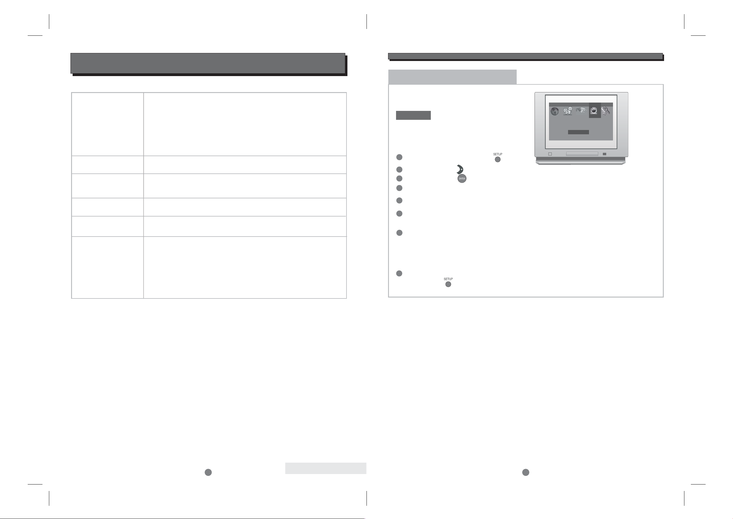
ESSENTIAL SETUP
2
Audio outputs (analogue)
The player can provide either stereo (Left
and Right) output or 5.1 channel decoded
output (from Dolby Digital Sources).
DEFAULT
Factory default audio output is:
(Downmix)
Stereo Left and Right only
For 5.1 decoded output connection,
the following setup is required:
After system connection is completed (see " SYSTEM
CONNECTION"), setup as following steps:
In STOP mode, press button ,
setup menu appears.
SETUP
1
2
3
Highlight "Spkr Setup" icon, press button,
sub menu appears.
ENTER
Highlight the connected speaker's name,
press button to switch ON or OFF the
speaker. .
ENTER
Highlight “C S Spkr Size” and press
button to select Large or Small Centre and
Surround speakers. If “Large” is selected the
speakers will receive the full frequency range.
If “Small” is selected the bass frequencies in
the centre and surround channels will be
redirected to the subwoofer.
ENTER
Highlight “5.1 Channel” icon, press
button.ENTER
After setting all speakers, Press
button to quit.
SETUP
Press button highlight "Audio 2" icon.RIGHT
Press button , sub-menu appears.ENTER
4
5
6
7
8
.........
.........
.........
.........
.........
.........
.........
.........
.........
.........
.........
.........
.........
.........
.........
.........
.........
.........
.........
.........
.........
.........
.........
.........
.........
.........
.........
.........
.........
.........
.........
.........
.........
.........
.........
.........
.........
.........
.........
.........
.........
.........
.........
.........
.........
.........
.........
.........
.........
.........
.........
.........
.........
.........
.........
.........
Language Video Audio 1 Audio 2 Rating
Pro Logic
Cent Delay
Surr Delay
Spkr Setup
Off
0ms
0ms
Down Mix
INTRODUCTION
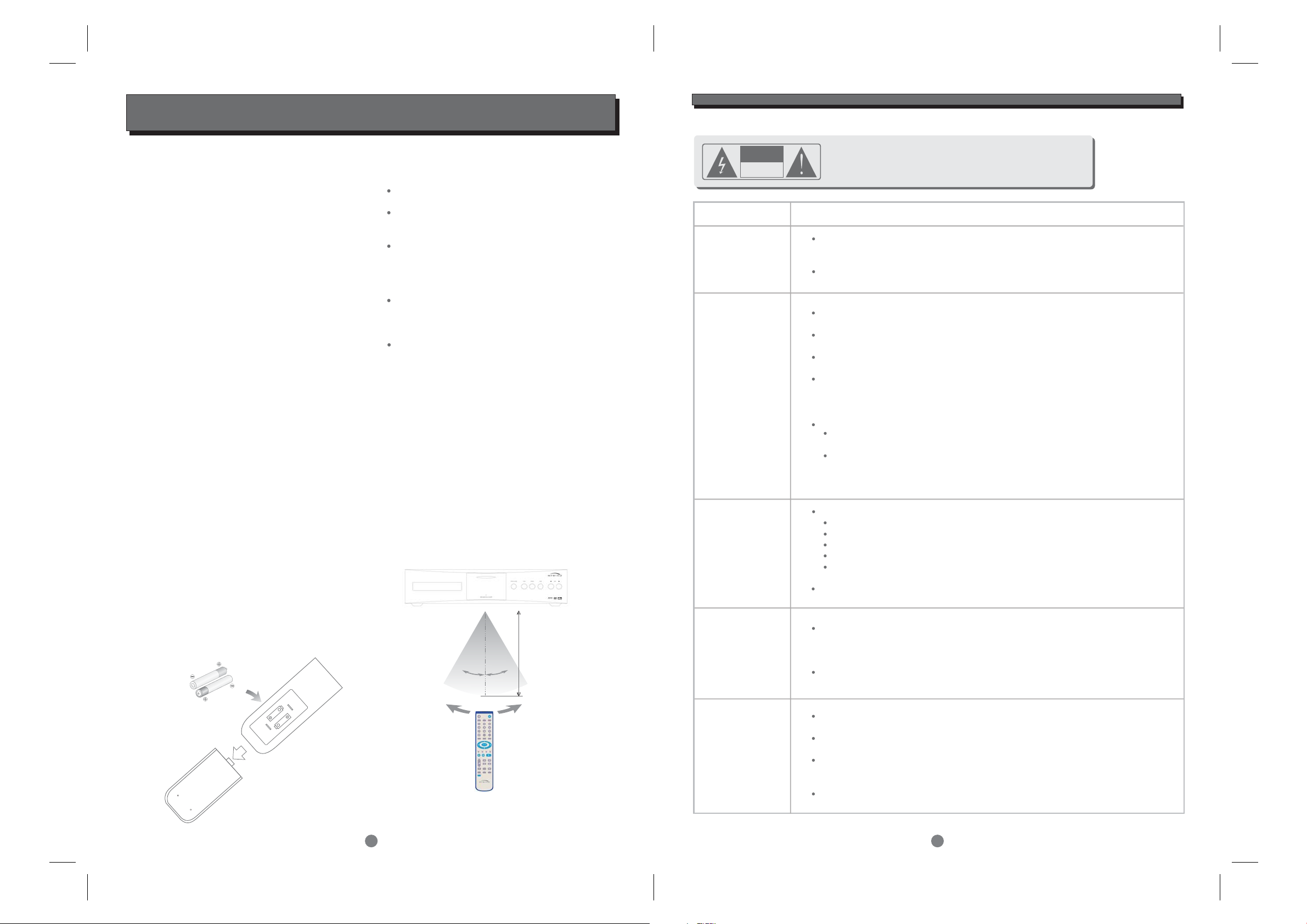
LOADING BATTERIES INTO THE REMOTE CONTROL
Remove the battery compartment cover.
Load two AAA (UM-4 or R03) batteries into the
battery compartment.
Check that batteries are fitted correctly and that
the polarity of the batteries matches the polarity
indicated in the battery compartment. Replace
the battery compartment cover.
Always replace both batteries. Do not mix new
and used batteries as this will reduce the
operating period.
Remove the batteries if the unit is not be used
for a prolonged period of time.
Loading batteries into the remote control
The remote control transmits a directional
infrared beam. Be sure to aim the remote
control directly at the infrared sensor of the
unit during operation.
Ifthesensorhasbeencoveredorthereisa
large object between the remote control and
the sensor, the sensor may not respond.
The sensor may not able to receive the
remote signal when it is exposed to direct
sunlight or a strong artificial light (fluorescent
or strobe light). In these instances, change the
direction of the light or reposition the unit to
avoid direct lighting.
2
3
UM-4
+
UM-4
+
30
o
30
o
Within approximately
6 metres (20 feet)
Accessories
Your MXV 3000 is supplied with the following
accessories:
- Separate mains power cord to suit country
of sale.
- My-Link interconnect (0.5m RCA-RCA).
- MXV 3000 remote control handset.
- TwoAAA batteries for handset
(not in some countries).
Introduction
The Myryad MXV 3000 DVD-Video Player has been
designed to offer a combination of high quality
sound reproduction and elegant styling in keeping
with other Myryad products. The MXV 3000 is a
full-function remote controlled DVD-Video player.
It has fixed-level low-impedance audio outputs to
drive a Myryad pre-amplifier or integrated amplifier
or other high quality amplifier. Video outputs are
provided in composite, s-video and component form
and can be fed to an audio-video preamplifier (such
as the Myryad MDP 500 G6), amplifier or direct to
a TV. In addition the MXV 3000 has coax and
optical digital outputs (SPDIF standard) to feed a
digital surround processor and a Smart My-Link
control input and output.
The MXV 3000 offers a range of expansion
possibilities:
- The My-Link can be connected to a Myryad preamplifier or integrated amplifier so that the
MXV 3000 will be switched on or off when the
amplifier is switched on or off.
- The My-Link input/output can be coupled to
other Myryad products that can then be remotecontrolled via the MXV 3000’s infra-red receiver,
or vice-versa.
- When linked to a “Smart My-Link” compatible
Myryad preamplifier or integrated amplifier a
number of extra features become available
which make the system as a whole easier and
quicker to operate.
TROUBLESHOOTING
28
Symptom Check and Action
Cannot SKIP
or SCAN
Some discs are programmed to prevent users using SKIP or SCAN
at some sections, especially at the beginning WARNING section.
SKIP does not work with single Chapter discs.
No sound or
poor quality
sound
Check that the TV and Amplifier have been switched on, and correctly set.
Check that the TV and Amplifier are correctly connected..
Press AUDIO button to select an alternative audio track.
Check that the MUTE function of the TV or Amplifier is not active
There will be no sound output during REVERSE PLAY / PAUSE / STEP /
SLOW and SCAN.
DTS discs used and no sound from TV.
Select an alternative audio track by pressing the remote control
"AUDIO" button, or by using setup in the disc menu.
Connect the digital audio output to a digital amplifier (or pre-amplifier
such as, for example, a Myryad MDP 500 G6 Pre-amplifier Processor).
No surround
sound
If digital output has been activated:
Press SETUP button
Highlight "AUDIO"
Highlight "DIGITALOUTPUT"
Select BITSTREAM or LPCM
Press SETUP button
Check that the amplifier or active type loudspeakers are switched on..
MP3 disc no
sound or noisy
Remote control
does not function
When PC program files or other data files are mixed with
MP3 files on the same disc, the player may play the non-MP3
files with noise or no sound.
Check the disc, if all the files on disc are MP3 files
Skip the file, try other files.
Remove the obstacles between the remote control and the player.
Point the remote control towards the remote sensor on the player.
Check that the batteries of the remote control have been loaded
correctly.
Replace the remote control batteries.
CAUTION : To reduce the risk of fire and electric
shock, do not remove the cover (or back) of the unit. Refer
servicing only to qualified service personnel.
RISK OF ELECTRIC SHOCK
DO NOT OPEN
CAUTION
 Loading...