

Myryad MXP-2000 Owners manual
MXP2000
Remote Controlled
Stereo Preamplifier
Owner’s Manual

CONTENTS
• Introduction 2
• Installation and Safety 2
• Accessories 2
• Setting up your system 3
• Rear panel connections 3
• Using your MXP2000 4
• Front panel controls 4
• System operation
with Smart My-Link® 5
• Remote Control
Handset Operation 5
• Using the menu system
to customise your preamplifier 6
• Installing and replacing
batteries in the remote control 7
• Trouble-shooting guide 7
• Specifications 7
INTRODUCTION
The Myryad MXP2000 Stereo Preamplifier
has been designed to deliver a combination
of high quality sound reproduction and
elegant styling.
The MXP2000 can accept up to eight linelevel input sources, including two tape
recorders. Two pairs of line outputs are
provided to feed one or two stereo power
amplifiers. All functions can be operated
using the infra-red remote control handset
supplied. This remote can also control
Myryad CD players, Tuners and DVD
players.
The MXP2000 offers a range of expansion
possibilities:
• The second pair of line outputs may
be used to feed a second Myryad
Power Amplifier to allow bi-amplified
drive of suitable loudspeakers.
• The My-Link input/output can be
coupled to other Myryad products
which can then be remote-controlled
via the MXP2000’s infra-red receiver
or vice-versa.
• When linked via the Smart My-Link®
to other compatible Myryad M-Series,
MX-Series, Z-Series or Cameo
products a number of other features
become available which make the
system as a whole easier and quicker
to operate.
INSTALLATION AND
SAFETY
This preamplifier generates a small amount
of heat and thus requires some ventilation.
Do not place it on a rug or other soft surface
into which it could sink, obstructing the air
inlets in its underside. The preamplifier
should not be installed in a built-in situation
such as a bookcase or rack unless proper
ventilation is provided
CAUTION: TO PREVENT A FIRE OR
SHOCK HAZARD, DO NOT PERMIT THIS
PRODUCT TO BECOME WET. IF LIQUID
IS ACCIDENTALLY SPILLED ON IT,
IMMEDIATELY SHUT OFF ITS POWER AT
THE WALL SOCKET AND UNPLUG THE
AC POWER CORD. ALLOW SUFFICIENT
TIME FOR COMPLETE EVAPORATION TO
OCCUR BEFORE OPERATING THE UNIT
AGAIN. IF THE LIQUID IS ANYTHING BUT
WATER AND/OR ALCOHOL, A QUALIFIED
SERVICE TECHNICIAN SHOULD
EXAMINE THE UNIT BEFORE IT IS USED
AGAIN
Do not remove the cover, or attempt to
modify or repair the amplifier yourself. Refer
all servicing to a qualified technician.
ACCESSORIES
Your MXP2000 is supplied complete with the
following accessories:
• Separate mains power cord to suit
country of sale.
• Myryad Slim System Remote.
• Two AAA batteries for handset.
• Slim System Remote Owner’s Manual.
2
SETTING UP YOUR
1
2
344
567
8
9
10
11
12
SYSTEM
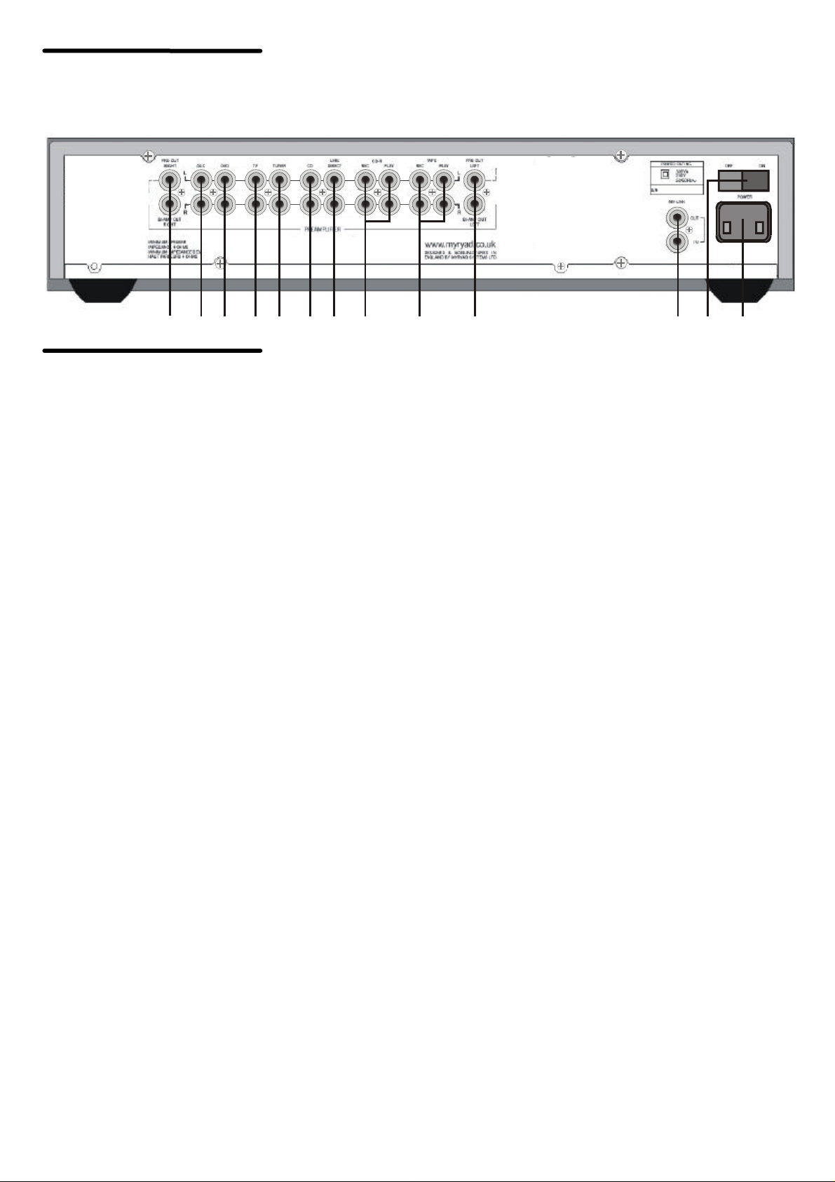
REAR PANEL
CONNECTIONS
1. Power Inlet
Before making any connection, check that
the mains voltage setting printed on the
rear panel is the same as your local mains
supply.
Plug the female (socket) end of the power
cord into the power inlet on the rear of the
amplifier. Plug the male (plug) end of the
cord into a "live" wall socket or a suitable
heavy duty extension cable.
UK version: The mains plug is supplied
fitted with a 5A fuse. It should only be
replaced with a fuse of the same rating (5A)
which complies with BS1362.
2. Power Switch
Press one side of this rocker switch (the
side nearer the edge of the rear panel) to
switch the amplifier ON and the other side
(towards the audio connectors) to switch it
OFF. When the POWER switch is in the
OFF position all power is disconnected
from the amplifier. In this condition the
amplifier cannot be powered up from the
front panel or the remote control. When the
POWER switch is in the ON position (and
the power cord correctly inserted and
plugged into a live wall socket) the amplifier
will power up in standby mode (see Front
Panel Controls, STANDBY, below).
3. My-Link input/output
When the MXP2000 is used in a system
with other Myryad products (e.g. MXSeries, M-Series, Cameo or Z-Series), all
may be joined together via the My-Link.
The My-Link is a communications bus that
allows all the linked components to operate
together as a system and distributes the
remote commands received by any one to
each of the others. The simplest function
provided by the My-Link bus is that all
linked units will switch into or out of standby
mode when the MXP2000 is switched into
or out of standby – either from the front
panel or the remote control.
Use a short RCA-to-RCA (phono-to-phono)
interconnect cable to connect from the
MY-LINK OUT socket on the MXP2000 to
the MY-LINK IN socket on the next unit
(e.g. Myryad power amplifier). A second
cable may then be run from the MY-LINK
OUT socket of that unit to the MY-LINK IN
socket on the next and so on in “daisychain” fashion. Further compatible Myryad
products can be linked in the same way.
Inexpensive interconnects may be used as
the My-Link bus carries only control signals,
not audio, so these cables have no effect
on sound quality. Suitable interconnects are
supplied with Myryad CD players, Tuners,
DVD players and Power Amplifiers.
When Myryad products equipped with
Smart My-Link® are connected to the
MXP2000 via the My-Link, many more
powerful system features are available (see
SYSTEM OPERATION WITH SMART
MY-LINK ® page 6).
4. Line outputs (1 and 2)
Each of these pairs of line outputs is
designed to feed the line inputs of a Myryad
power amplifier or any other high quality
power amplifier. In a conventional setup
only one output pair is used to feed a single
stereo power amplifier. The second pair of
outputs can be used for a variety of
applications – including “bi-amplification”.
Many loudspeakers today are made so that
the bass and treble sections can be
separated and fed from two sets of speaker
cables. This is known as "bi-wiring" and can
yield a significant improvement in sound
quality. A further sound quality gain may be
made by "bi-amplifying" the loudspeaker using two separate power amplifiers to
drive the bass and treble sections.
The two pairs of line outputs on the
MXP2000 can be used to feed two separate
Myryad power amplifiers which should
normally both be the same model. The
amplifiers would be connected, for
example, so that one drives the bass
sections of the loudspeakers (left and right)
while the second drives the treble. Further
information on bi-amplifier and tri-amplifier
3
system wiring can be found on the Myryad
website www.myryad.co.uk.
5. Tape input/output
The Tape inputs and outputs are suited to
any type of tape recorder, including highquality "3-head" types which allow you to
monitor the signal off the tape whilst it is
being recorded. Connect a stereo cable
from the TAPE REC output sockets of the
amplifier to the LINE IN or RECORD IN
sockets on your tape deck. Connect a
second stereo cable from the TAPE PLAY
input sockets of the amplifier to the LINE
OUT or PLAY OUT sockets on your tape
deck.
Any source selected for listening on the
MXP2000 (apart from LINE DIRECT) will
automatically be fed to the TAPE REC
output sockets for recording. If the CD-R
input is selected then tape copies may be
made from CD-R to TAPE. It is NOT
possible to copy from TAPE to CD-R.
6. CD-R input/output
The CD-R inputs and outputs are suited to
the analogue outputs/inputs of a digital
recorder (e.g. CD-R or Mini-Disc) or any
type of analogue tape recorder, but "offtape" monitoring is not possible using the
CD-R input. The wiring from CD-R to your
tape deck is identical to the TAPE wiring
described above. Any source selected for
listening (except TAPE or LINE DIRECT)
will automatically be fed to the CD-R REC
output sockets for recording. It is NOT
possible to record from TAPE to CD-R.
7. Line Direct input
The LINE DIRECT input provides the
shortest, cleanest signal path through the
amplifier and will deliver the best sound
quality of all of the MXP2000’s line inputs.
The audio output from any high quality line
level source may be connected to this
input. It is not possible to make a recording
from a source connected to the LINE
DIRECT input using the MXP2000’s TAPE
or CD-R REC outputs.
 Loading...